As noted in Chapter 12, there are two subcategories that fall under the DTV (Digital Television) category of standards: SDTV (Standard Definition Television) and HDTV (High Definition Television). All high definition video, also referred to as high def or HD, falls under the HDTV category of standards. Analog television standards, including NTSC, PAL, SECAM, and variations of these standards, are not compatible with each other and converting images from one standard to another requires a process that can degrade the image quality. HDTV represents an international effort to create more compatibility between world standards.
Setting High Definition Standards
In the early 1990s, another organization, the International Telecommunication Union (ITU), became involved in recommending television standards. The ITU is the United Nations specialized agency for bridging gaps throughout the world in Information and Communication Technologies (referred to as ICTs). There are different sectors of the ITU, and the sector that addresses recommended uses in the television industry is the Radiocommunication sector, or ITU-R. The ITU-R study group that focuses on video is the Broadcasting Service (Television) study group. And the recommendation that group laid out for high definition standards is the document, ITU-R Recommendation BT.709.5 (parameter values for the HDTV Standards for production and international program exchange).
NOTE The ITU is committed to connecting all the world’s people—wherever they live and whatever their means. They allocate global radio spectrum and satellite orbits, develop the technical standards that ensure networks and technologies seamlessly interconnect, and strive to improve access to ICTs to underserved communities worldwide. Through their work, they protect and support everyone’s fundamental right to communicate.
To create a unified approach to adopting standards, three of the world’s leading international standards organization came together in 2001 to form the World Standards Cooperation (WSC). This organi zation was established by ISO, ITU, and the International Electrotechnical Commission (IED). The purpose of the WSC moving forward is to strengthen and advance the voluntary consensus-based international standards systems of ISO, IEC, and ITU.
Today, there are several different high def standards, each with its own unique combination of image criteria, including frame rate, pixel count, line count, and scanning mode.
Widescreen Aspect Ratio
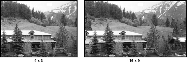
CDTV and SDTV standards use an image size with an aspect ratio of 4 × 3. A 4 × 3 image is four units wide by three units high. While rectangular in shape, it is much closer to a square than the wide-screen image currently seen in cinemas. The human eye perceives a great deal of motion and depth information from the area outside of direct view. This area is known as peripheral vision. Having a
wider video image area takes advantage of this characteristic and improves the sense of reality for the viewer.
As HDTV was developed, this fact was taken into consideration and all HDTV standards were widened to a 16 × 9 aspect ratio, or an image that is nine units high by sixteen units wide (Figure 13.1). Since the HDTV standards all have a 16 × 9 ratio, it is often referred to as the aspect ratio for the standard. A native standard is the basic standard for which the piece of equipment was designed. It may be capable of handling other standards, but its original intent is called the native standard.
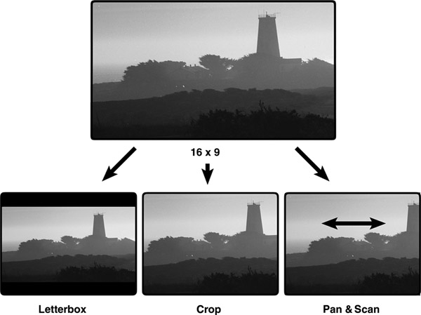
Widescreen video can be played back on a 4 × 3 monitor in different ways. To see the entire widescreen image, the image must be reduced in size so the width of the image fits on the 4 × 3 monitor. This creates black above and below the widescreen image, a layout often referred to as letterbox. To make use of the full 4 × 3 image area, the sides of the widescreen image can be cropped to show just the middle portion, or 4 × 3 area. Also, a process of panning, or moving horizontally across an image, can be applied during transfer to reveal a particular portion of the widescreen image. This process is often called pan and scan (Figure 13.2).
4 × 3 material can also be displayed on a widescreen monitor. The content creator can choose how to deal with the aspect ratio conversion. If the top and bottom of the smaller image is enlarged to touch the top and bottom of the 16 × 9 raster, an empty area will be remain on the left and right of the image. If this is left black it is referred to as pillar box presentation. When graphic elements are added on the sides, the term wings is sometimes used for the left and right black areas. Finally the image can be enlarged further, matching the left and right edges of both aspect ratios. This will discard a portion of the top and bottom of the original 4 × 3 frame. It also leads to quite visible softening of the image.
HD Image Resolution
With the 16 × 9 aspect ratio, there is a larger image area and therefore more room for additional pixels. Different high def standards have different pixel and line counts that make up that standard’s image area. The greater the number of pixels that make up the image, the greater the image resolution.
For example, one high def format has an image resolution of 1920 × 1080. In this format, there are 1920 pixels across one line and 1080 lines in one frame of the image. The 1920 pixel count is the horizontal resolution, and the 1080 line count is the vertical resolution. Another high def standard is 1280 × 720, which is 1280 pixels per line by 720 lines. The combined pixel and line count make up the spatial density resolution of the high def image.
Ultra High Definition
Much like the rapid increase in megapixel count for still image cameras, video systems continue to develop higher resolution imaging. As technology develops faster processing, better compression algorithms and more precise manufacturing techniques, higher resolution equipment is possible. Images that have a higher resolution than the standard HD are referred to as UHD, or Ultra High Definition.
4K
As of this writing, the highest resolution equipment available is called 4K, as the image has approximately 4000 pixels in each scan line. The actual number for a true 4K image is 4096 pixels per line, with 2160 lines in each frame. This size is used for Digital Cinema photography and projection. The aspect ratio for this format is 1.9:1, just a little wider than the common 1.85:1 used by many feature films.
Television broadcast and home monitors are a slightly different format called UHD or Ultra HD. This format is exactly double the 1920 ´ 1080 pixels of standard HD. The UHD frame is 3840 pixels on 2160 lines. This produces an image that is four times the pixels as the largest HD frame.
While the 4K format is in the early stages of adoption, a variety of production equipment and cameras are available to create content in this format. Displays for home use are also available. While development on ways to get the content from the producers to the home is ongoing, at this time there are limited ways to deliver 4K content. Netflix has 4K series available via web delivery and You-Tube is playing 4K content. There are also a few movies available on specialty players. Just as HD grew to proliferate the television marketplace, it’s expected that 4K will become the television standard by 2017.
One advantage of capturing images in 4K for standard HD delivery is that scenes can be enlarged up to 2x without any softening or reduction of resolution. For example, an image originating as 4K would be perfectly clear on a sports replay when the image freezes and then zooms in to an area of interest in the frame.
8K
If 4K is good, will 8K be better? The broadcaster, NHK, in Japan is developing the next generation of High Resolution technology. Called 8K, this format has 7680 pixels on each of its 4320 lines.
This is almost twice as many pixels and lines as 4K. In addition, frame rates up to 120 fames per second are being considered for this format. To enhance the audio experience, the format specifies surround sound with 22.2 channels. NHK has shown the format in prototype form numerous times in recent years, and hopes to broadcast the format starting with the 2020 Olympic Games in Tokyo. In addition to NHK, Sony and Red Digital Cinema Camera Company are working to bring 8K sensors into their cameras in the coming years.
One advantage of working with 8K is that its super-high resolution allows for more options during the post production process. As mentioned above with 4K shooting a sports replay, with 8K you can shoot an image in wide shot, perhaps a potentially dangerous animal far away, and then digitally zoom and crop or pan and scan the image to use just the desired portion. The zoomed-in portion would still match the smaller resolution of the current industry standard HD televisions. Also, 8K camera sensors create sharper pictures and richer colors than a 4K camera. But the 8K image can be downsampled to 4K, creating a better picture with a lower resolution.
Modulation Transfer Function (MTF)
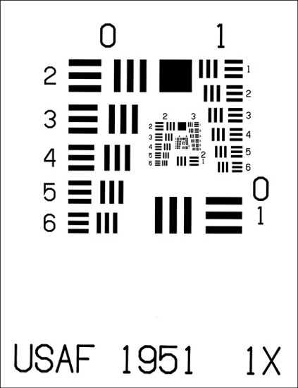
When discussing resolution, it’s easy to forget that the digital image sensors are capturing the analog world. While the technology of image capture advances at the rapid rate of computer systems, often the optical technology of the lens and prisms systems struggle to keep up. Optically, image sharpness and contrast are related and measured by something called the Modulation Transfer Function, or MTF. The way this is measured is by using imaging test charts that contain pairs of black and white lines (Figure 13.3).
NOTE This chart was developed by the U.S. Air Force in 1951, which is why you will sometimes see that information on the chart itself.
As the lines get smaller and closer together they become more difficult to reproduce. The edges of the lines become blurred together, mixing to produce soft gray images. The point where the lower contrast of the lines merge to gray represents the limit of sharpness the optical system can transfer to the image.
Although a cell phone or inexpensive camera may well make a 4K recording, the inexpensive mass-produced lens will not be able to create a high enough resolution to replicate clear line divisions in charts such as in Figure 13.3.
Progressively Segmented Frames
HDTV standards can use either of the two scanning modes, interlace or progressive. When a high def standard uses an interlace mode, the odd fields are transmitted first, followed by the even fields, just as they are in CDTV or SDTV. In progressive scanning, the entire image is scanned as one complete frame. This data may then be transmitted as a complete frame and received as a complete frame. If there is insufficient bandwidth to transmit the complete frame, the data may be segmented and transmitted in two parts.
Because progressively scanned images are complete frames of video, they require more bandwidth to transmit than may be available. To transmit these images within an interlace environment using narrower bandwidths, a process of segmenting progressively scanned frames was developed.
To do this, the image is divided into two fields by scanning every other line as in interlace scanning. The difference is that, in the interlace scanning process, the two fields are from different instances in time. When a progressively scanned image is segmented, the two fields are from the same instance in time. When the separate fields are recombined, the result is a complete progressively scanned frame (Figure 13.4).
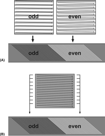
Figure 13.4(A) Interlace Scan and (B) Progressive Segmented Frame
This process accommodates the need to segment the data without compromising the quality of the image. Images that are progressively scanned and then transmitted as segmented frames are referred to as PsF, for Progressively Segmented Frames.
Frame Rate
Within the HDTV set of standards, there are numerous frame rates. The frame rates are part of a set of criteria that defines a particular HDTV standard. Each set of criteria was defined because of specific requirements within an existing physical environment. For example, North American electrical systems use 60-cycle alternating current, while European electrical systems use 50-cycle alternating current.
In addition, one of the major forms of image creation has been film. Film runs at 24 fps in North America and 25 fps in Europe. To minimize the difficulty in incorporating film into HDTV, a set of criteria was developed to accommodate the film frame rate. A different HDTV standard was created with a specific set of criteria based on the ease with which the new standard would interface with an existing system. Therefore, two of the many HDTV standards include 24 fps and 25 fps.
Film-to-Tape Conversion
There are many situations when film is transferred to HDTV, or HDTV to film. Film is often used as an archival medium because the film standard has not changed in generations. When film is used as the originating medium but the delivery requirement is video, film must go through a conversion process. Converting film to an electronic form is often referred to as telecine, which can also refer to the machine used in the conversion process. In PAL systems, the existing video frame rate matches the 25 fps film rate, and the conversion process is simply a matter of converting from one medium to the other. However, in the NTSC system, where the video frame rate of 30 fps does not match the film rate of 24 fps, a different conversion process must take place.
Converting Different Frame Rate Sources
Whether the need for conversion is from film to video or video to video, the HDTV 24 fps standard makes video and film more compatible with each other, especially in the United States where film is shot at 24 fps. However, to create 30 images per second in video from a source producing 24 images per second, additional video fields are added. This is done by duplicating images from the 24 fps source. The process of adding additional fields to create additional frames is known as a 2:3 pulldown system or sometimes as a 3:2 pulldown system.
The 2:3 or 3:2 pulldown process is used when 24 fps progressive scan video, used in image capture, must be converted to 30 fps for either editing or transmission. It is also used when transferring 24 fps film to 30 fps video. When transferring 24 fps film or video into a 30 fps video system, it is essential to decide which sequence will be used—2:3 or 3:2—and then maintain that sequence.
Using 2:3 and 3:2 Pulldown Sequences
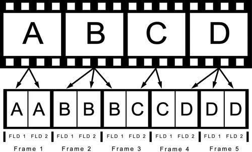
When transferring 24 frames per second in a 2:3 sequence, the system will map four frames from the original source to every five frames, or ten fields, to the transfer source. The first frame that is transferred is referred to as the A frame. It is transferred, or pulled down, to two video fields. The second frame is referred to as the B frame and is transferred to the next three consecutive video fields. The third film frame, the C frame, is transferred to the next two consecutive video frames. And the fourth frame, the D frame, is transferred to the next three consecutive video frames (Figure 13.5).
The resulting transfer process yields five video frames for every four original 24 fps source frames. Video frame 1 and video frame 2 are each derived from two separate film frames, A and B. Video frame 3, however, is a composite of one field from film frame B and one field from film frame C. Video frame 4 is also a composite composed of one field from film frame C and one field from film
frame D. Video frame 5 is composed of two fields, both from film frame D.
When scanning through video images that have been transferred using this process, the video frames that contain two different frames will appear as a double image. When these frames are viewed in motion, however, the double image is not discernible. When editing video that has been transferred from film using this pulldown process, the sequence of frames must be maintained. If the sequence of video frames is broken, for example by editing two combination frames consecutively, the resulting conflict of images will be discernible when displayed in motion.
When the pulldown sequence is changed to 3:2, the resulting frames yield a different result. The five video frames would be AA AB BC CC DD (Figure 13.6). Here the second and third frames are composite, rather than the third and fourth. In
the 3:2 sequence there is one clean frame followed by two composite frames followed by two clean frames. Therefore, when converting 24 fps to 30 fps, it is essential that one of these processes is applied consistently so the order of clean and composite frames will be maintained.
Maintaining Consistency in Pulldown Sequences
Just as the pulldown sequence must remain constant, so should the transfer process. Once the transfer of a scene or section has begun, it is essential the transfer be completed without stopping. If the transfer is stopped and then restarted in a single scene or sequence, the system will assume the first frame again is an A frame and begin the sequence from there. Later, when attempting to edit this sequence together in video, it is very possible that the frame sequence will have been broken and the edited version will contain overlapped images from incompatible frames. The result could be a stutter or jump in the images.
During the film or video transfer process, as the footage is digitized into the video system, a computer file can be created that will indicate where the associated composite frames are for each section. The added fields can also be seen and identified by scrolling through the video a field at a time. With a correctly compiled computer file, it is possible for a video system to extract and recombine the overlapping fields to create a clean 24 fps sequence from the 30 fps 2:3 or 3:2 pulldown sequence created in the video transfer. The process will discard the redundant fields used to create the 30 fps video from the original 24 fps material. This process is referred to as inverse telecine.
Converting an HD Signal
One of the primary differences between HDTV and SDTV is the increase in the amount of information that makes up the HDTV signal. Because of the number of pixels per line, lines per frame, and frames per second, HDTV has a greater spatial and temporal resolution. While the size of the image is larger and the resolution is greater, the recording, storage, and transmission processes remain similar. Because of these similarities, HDTV signals may be converted to other standards.
Converting HDTV to SDTV or CDTV is referred to as down converting. In the downconversion process, the number of lines and the number of pixels per line are reduced to fit the targeted standard. For example, a HDTV image that is 1920 × 1080 could be reduced to a 720 × 480 SDTV image. The reduction is achieved by deleting some lines and pixels in the downconversion process. The consequence of this is a reduction in image resolution, though the aspect ratio may remain the same. However, in some situations when a 16 × 9 image is reduced to 4 × 3, the 4 × 3 image may appear as though it had greater detail than the original.
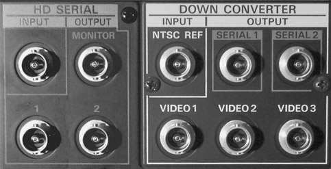
Downconversion is used when an HDTV native image needs to be used in an SDTV or CDTV environment. For example, a program can be shot in HDTV, but transmitted or broadcast in SDTV or even CDTV. Also, if the editing process is configured with SDTV or CDTV equipment, a downconversion from HDTV allows the editing to occur within the existing post production environment. Some HD VCRs are even equipped to downconvert a signal internally (Figure 13.7).
CDTV or SDTV can also be converted to an HDTV standard through a process called upconverting. The upconversion process increases the number of lines and the number of pixels per line to fit the targeted standard. This involves, in some instances, duplication of information to fill in the additional spatial resolution. This does not increase the detail in the image nor the apparent resolution. It merely increases the pixel and line count.
Upconversion is used when taking a CDTV or SDTV image and enlarging it to fit in an HDTV space. For example, an older television program that originated in CDTV may be upconverted to HDTV or SDTV for current broadcast. Some equipment contains a downconversion/upconversion circuit within the machine itself.
In other cases, the conversion process is accomplished through an outboard or stand-alone device.
HDTV Applications
Because of the different HDTV scanning types and frame rates, HDTV images may look different with each standard. A faster scan rate, or temporal resolution, typical of interlace scanning, gives more frequent image information because it scans an image twice for each frame, once for the odd lines and again for the even lines. The scans are created in different moments in time. This process refreshes the image more frequently than progressive scanning. Therefore, interlace scanning is often used for images that contain a great detail of motion with a lot of action. For example, football games are often shot using 60-field interlace (60i) HDTV. The more frequent scanning of the image fields produces a greater number of images in a given amount of time, creating a smoother transition from field to field and frame to frame.
An HDTV image shot in 24p, or 24 fps progressive scanning, gives a less frequent scanning rate or slower temporal resolution. Shooting in 24p means it takes longer to scan a full frame because successive lines must be scanned. A 24p frame rate creates a softer, film-like look. In 24p, rapid motion is not advisable because the slower temporal resolution cannot capture enough motion detail to track the action clearly.
One of the reasons 24p was developed as a standard was to match 35mm motion picture film, both in terms of temporal and spatial resolution. Certain television programs that originated in SD video are converted to HDTV for archival and sometimes broadcast purposes. However, shows that were created after the advent of HDTV, but during the time HDTV standards were still being defined, turned to film for production purposes. This allowed the shows to be both archived in film, an established medium, and converted to any video standard at a later date.
Non-Picture Data
Digital video uses a data stream to carry picture information, but there is also non-picture data mixed in with it. Some of this non-picture data contains sync and color information, and some of it contains information about the picture data stream itself. This digital data stream also contains information about which standards are being used.
Vertical Ancillary Data (VANC)
In analog video signals, the vertical blanking interval between fields was used to carry synchronizing information and eventually included test signals, timecode and closed captioning data. In digital video this data has now been incorporated into the data stream and is included under the heading of VANC, or vertical ancillary data. VANC is created and encoded into the data stream through a data encoder that creates and can also retrieve the information. The data to be encoded is programmed in by the operator through a series of menus built into the encoder.
Horizontal Ancillary Data (HANC)
In addition to VANC, there is also HANC or horizontal ancillary data. This is analogous to the data carried in the horizontal blanking interval that relates to line-by-line synchronization and color synchronization.