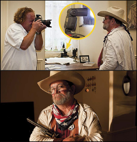
Figure 12.1 Mastering Canon’s wireless systems takes practice. If you stick with it, your efforts will be rewarded many times over. So, call up a friend and practice, practice, practice.
CANON’S OPTICAL AND RADIO WIRELESS SYSTEMS
THE OPTICAL MASTER: SOMEONE HAS TO BE IN COMMAND
THE OPTICAL SLAVE: WORKER BEE OF WIRELESS FLASH
MASTER AND SLAVE SETTINGS FOR OPTICAL WIRELESS
USING A POP-UP FLASH AS AN OPTICAL MASTER
ACTIVATING A SPEEDLITE AS AN OPTICAL MASTER
MOVING YOUR MASTER SPEEDLITE OFF-CAMERA
TO FIRE OR NOT TO FIRE: THE OPTICAL MASTER WANTS TO KNOW
ACTIVATING A SPEEDLITE AS AN OPTICAL SLAVE
CHANNELS: MASTER AND SLAVES MUST BE THE SAME
GROUPS: ASSIGNING JOBS TO SPECIFIC SPEEDLITES
ADJUSTING E-TTL FLASH POWER IN OPTICAL WIRELESS
A:B C RATIOS: THREE-GROUP E-TTL
ADJUSTING MANUAL FLASH POWER IN OPTICAL WIRELESS
ADJUSTING MULTI FLASH POWER IN OPTICAL WIRELESS
ACTIVATING A SPEEDLITE AS AN INDEPENDENT SLAVE
There are many concepts to learn when starting with Canon’s optical and radio wireless systems. This chapter will get you started with the fundamental concepts of Canon’s optical wireless system. Then, in Chapter 13 : Radio Wireless, The Canon Way we will go deep into the buttons and dials of Canon’s newest system.
Figure 12.1 Mastering Canon’s wireless systems takes practice. If you stick with it, your efforts will be rewarded many times over. So, call up a friend and practice, practice, practice.
The main idea behind Canon’s two wireless systems—optical and radio—is that a master device sends instructions to slaved Speedlites. These instructions will tell the slaves which mode, power, and sync settings to use.
Prior to the introduction of the radio-enabled 600EX-RT Speedlite, we never used the word optical with wireless—it was all optical. Now this is a very important distinction.
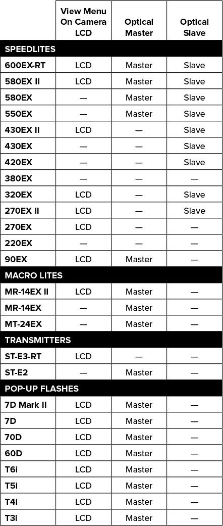
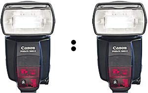
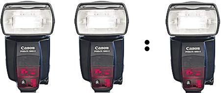
As shown in Figure 12.3 , Canon offers a wide range of devices that can serve as an optical master. The common link among all of them is that they emit their instructions as a coded series of pulsed light from the flash tube. Changes made on the master will be sent to the slaves when it next fires.
As with the E-TTL pre-flash, this pulsed light often is not seen separately from the main burst of flash. Also like the E-TTL pre-flash, the optical communication from master to slave will cause strobes and other flashes that use optical slave eyes as triggers to fire prematurely.
In optical wireless, the communication is one-way—from master to slave. A key element for success with optical wireless is that the slave must be able to see the instructions coming from the master. I have many techniques to share with you in this regard.
Canon’s 600EX-RT Speedlite and the ST-E3-RT Transmitter use 2.4 Ghz radio waves for two-way communication between master and slave. The advantages of radio are that the signal will radiate in all directions, reach out much farther, penetrate walls, and remain invisible.
As shown in Figure 12.3 , there are five Speedlites, three Macro Lites, one transmitter, and eight cameras with pop-up flashes that can serve as an optical master. Throughout this chapter, the word master will refer to any of these devices unless specifically stated (master Speedlite , for example).
There can only be one master in a Canon optical system. The master’s job is to send the instructions to the slave Speedlites. These instructions can be programmed in via the buttons and dials on a master Speedlite or Macro Lite. On compatible cameras, the instructions can also be set via the menu on the camera. For me, this is the easiest way to control a system of wireless Speedlites—especially on cameras with touchscreens (70D, T3i, T4i, T5i, EOS M).
In Canon’s optical wireless system, the master’s flashtube is the transmitter. Just before the shutter opens, the master sends the instructions to the slaves as an ultra-fast series of light pulses, hence the name optical wireless .
When it comes to optical wireless, there is virtually no difference between the power of the 600EX-RT and the 500-series. If you are indoors or outdoors under clouds or in the shade, these masters can approach a range of 45′. If you are outdoors in bright sun, the range will drop to around 30′. The range of a pop-up master is smaller—about 30′ indoors and 20′ outdoors.
Optical wireless requires that there be a visual path between the master and slaves. This path can be direct or it can be indirect—such as when the master’s signal is bounced off a light-colored wall.
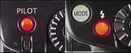
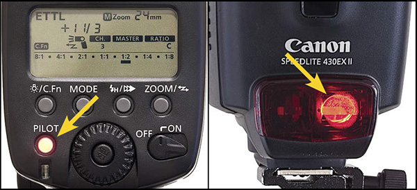
To confirm that a slave can see the master, fire a test flash by pushing the Pilot/Test button on the master. The slaves will respond by firing Group A, Group B, and then Group C.
Figure 12.4 To test whether an optical slave can see the master’s signal, push the Pilot / Test button on the master Speedlite. Left: 580EX II. Right: 600EX-RT.
If a slave does not respond, confirm that it is on the same Channel as the master, that it is powered on, and that it is facing the master.
There are two conditions that break the visual path between master and slave:
 Extremely bright ambient light
—Such as the sun when shooting optical wireless outdoors during midday
Extremely bright ambient light
—Such as the sun when shooting optical wireless outdoors during midday
Opaque barriers
—Such as walls and the fabrics used in light modifiers
The section Moving Your Master Speedlite Off-Camera later in this chapter explores options to deal with both of these situations.
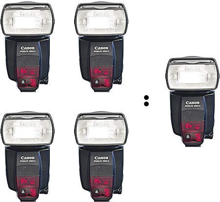
Although there can only be one master, there can be any number of Speedlites in optical slave mode. The only limitation is that all of the optical slaves have to see the flashed commands coming from the master. For the list of Canon Speedlites that can be an optical slave, see Figure 12.3 .
The slave’s job is to follow the instructions coming from the master. So there are only a few settings that you need to make on a slave—all of which were listed in the next section. These settings must be made directly via the buttons and dials on each slave.
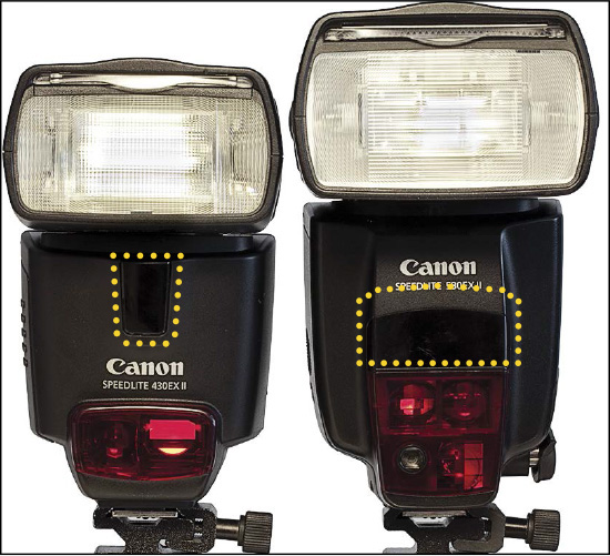
On Canon Speedlites, the optical wireless sensor is hidden behind a black panel on the front of the Speedlite. Many mistakenly believe that the large red panel is the receiver. Actually, this is the home of the Auto-Focus Assist beam. Again, the wireless sensor is the dark panel above the AF-panel.
Figure 12.5 The optical slave sensor is the small black panel above the red Auto-Focus Assist panel, shown here outlined in yellow dots on the 430EX II (left) and the 580EX II (right).
An optical slave will let you know that it is recycled and ready to receive by blinking a light through the AF-Assist panel on the front. I find this a helpful way to confirm that a Speedlite is in slave mode. If the blinking is bothersome, a bit of gaffer’s tape will solve the problem. The master does not blink.
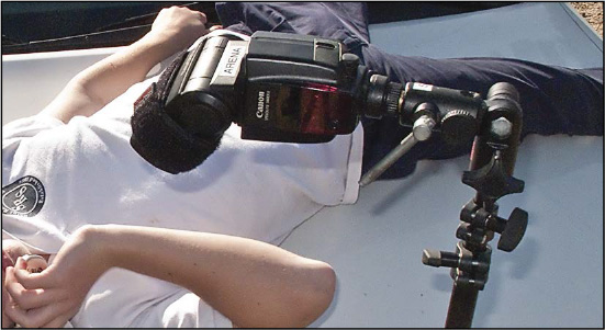
The main reason that Speedliters do not have success with Canon’s optical wireless is that they do not follow this essential tip: The front of the slaved Speedlite must face the direction from which the master’s instructions will come.
You should always turn the slave so that its front panel faces the master and then use the pan/tilt button to release the head so that you can aim the flash at your subject.
Figure 12.6 Twist the body of the slave Speedlite so that its front panel faces the master and then use pan/tilt to aim the head at your subject.
The master communicates many details to the slave. If you change the master from E-TTL to manual mode or activate High-Speed sync, the slave will follow when the master next fires.
One detail that is not communicated by the master to the slave is the Zoom setting. By default, when set to slave mode, a Speedlite will automatically zoom its flash head to 24mm. If you manually Zoom the master to 105mm, the slave will not follow. You have to do this by hand on each slave.
The basic idea of Canon wireless—either optical or radio—is that a master unit connected to the camera sends instructions to the slaves. There are several settings that must be made on the master and a few that are made on the slave. The details on how to make these settings follow later in the chapter.
Most of the settings for an optical wireless shoot are made on the master. Essentially, you must make every setting that you would normally when shooting a Speedlite, plus the wireless settings.
Activate
—Turn the wireless system on by activating the master flash.
Mode
—The default mode for optical wireless is E-TTL. You can change the mode to Manual and, if using a Speedlite as master, to Multi by pushing the Mode button.
Channel
—Master and slave must be on the same channel to communicate. Choose 1, 2, 3, or 4. Adjacent Speedliters working on different channels will not interfere with each other’s gear.
Group ID
—The master is always a member of Group A. Slaves can be assigned to groups A, B, or C. The purpose of assigning different group settings is to enable slaves to fire at different power settings. [Note: The optical Group ID setting is not the same as the new Group mode used with radio wireless.]
Flash Group
—You set the number of groups you want to control via Flash Group. ALL sets the master and all slaves to the same power regardless of Group ID. A:B gives you control of two groups (such as the master and an off-camera slave). A:B C (used in E-TTL) and A:B:C (used in Manual and Multi) control three groups.
Sync
—Speedlite masters offer 1st-Curtain and High-Speed Sync. Pop-up masters are 1st-curtain only. Canon disables 2nd-Curtain sync when the wireless system is activated.
On/Off or Enabled/Disabled
—If you have the master sitting in the camera’s hotshoe and you do not want on-camera flash in your shot, then you must choose Master Off or Master Disabled. I know that this wording is confusing. It just means that the master will send the instructions to the slaves (as an ultra-fast series of pulsed light) and then remain dark when the shutter opens. If you want on-camera flash (perhaps for a bit of fill light) or you have moved your master off-camera on an E-TTL cord and want its light in the shot, then choose Master On or Master Enabled. Again, in both cases it still is the master and still sends instructions to the slaves.
Position On- or Off-Camera
—Novice Speedliters expect that the master must be in the camera’s hotshoe. In fact, it only has to be connected to the camera’s hotshoe. If you have two Speedlites and you want both to create off-camera light, then use an extra-long E-TTL cord to move the master off-camera. Another reason to move the master, even if you do not need its light in the shot, is to enable the slaves to look away from the sun rather than into the sun for the master’s instructions.
Zoom
—The slaves must be able to see the instructions coming from the master. If you are working with one slave in bright ambient light (sunlight) and do not need light from the master in the shot, then zoom the master to 105mm/200mm and aim the head at the slave. This will increase the range. If you are working with several slaves, then you should keep the master zoomed wide so that the light signals reach all the slaves. However, do not pull out the prismatic wide-angle panel as this greatly reduces the effective strength of the flash by spreading it over an extremely wide area.
Note: When you make changes to the master’s settings, such as mode and sync, the changes will be sent to the slaves when the master next fires.
Only a few settings for optical wireless are made on the slave. Note that mode, FEC/power, and sync are not among them.
Activate
—Turn the Speedlite on as a slave.
Channel
—Set the channel to match the setting on the master—1, 2, 3, or 4.
Group ID
—Remember that the master is always a member of group A. So, if you want the slave to fire at the same power as the master assign it to group A or set the Flash Group ratio on the master to ALL. If you want the slave to fire at a power level different than the master, assign it to group B and set the ratio on the master to A:B. Use group C only if you truly have the need for three different power settings, in which case the ratio on the master should be A:B C.
Zoom
—You must zoom the flashhead of each slave individually. This cannot be done through the master.
Position
—Twist the body of the slaves so that the sensor (on the front) faces the direction from which the master’s signals will come. Then use pan/tilt to aim the head of the Speedlite towards your subject.
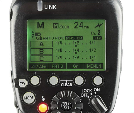
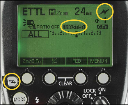
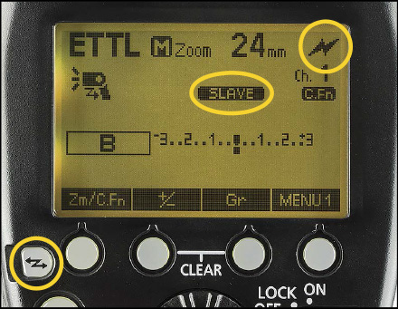
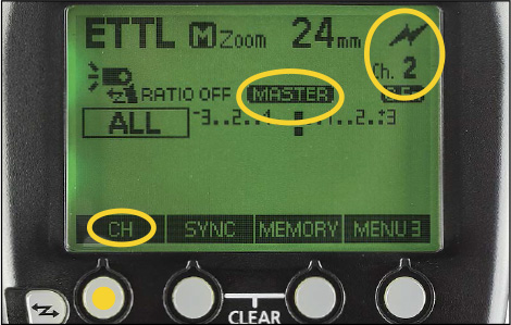
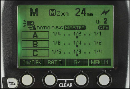
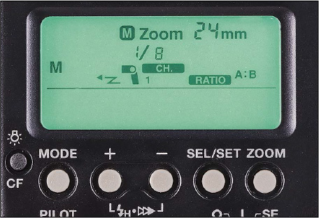
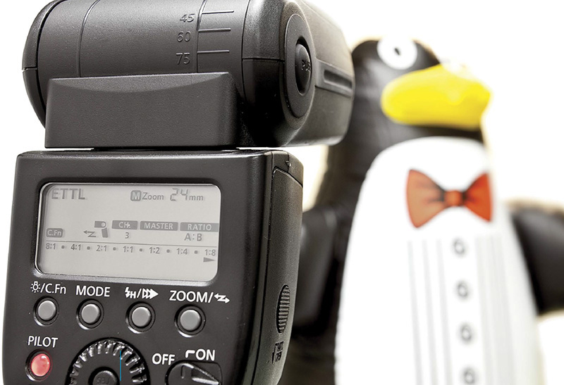
Figure 12.7 The LCD of a 600EX-RT set as optical master in Manual mode with power settings for three groups.
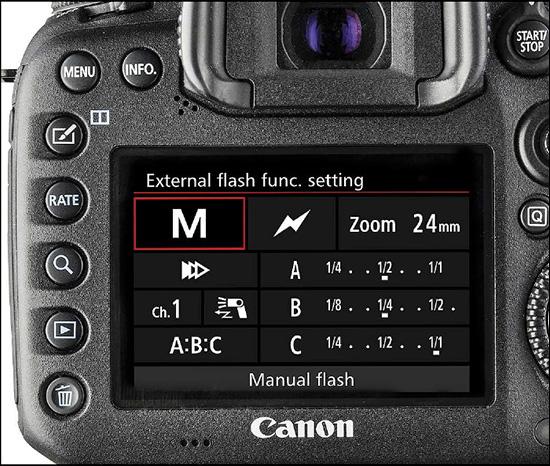
Figure 12.8 Quick Control menu on the LCD of my Canon 7D Mark II showing the same information shown on the Speedlite LCD in Figure 12.7 .
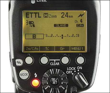
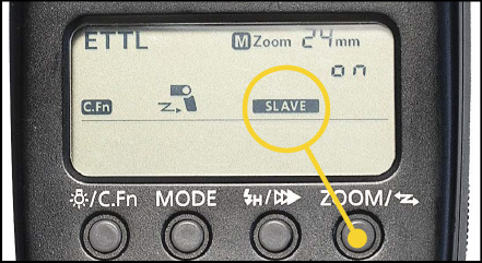
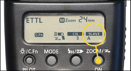
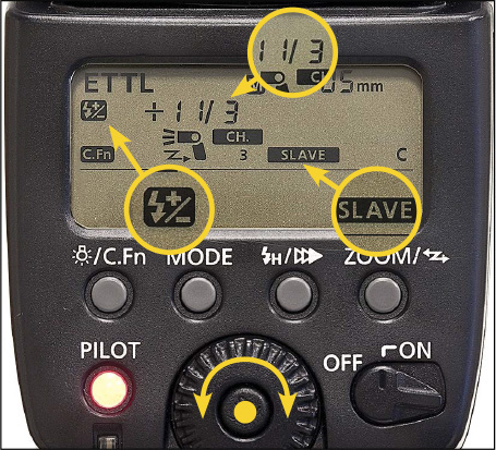
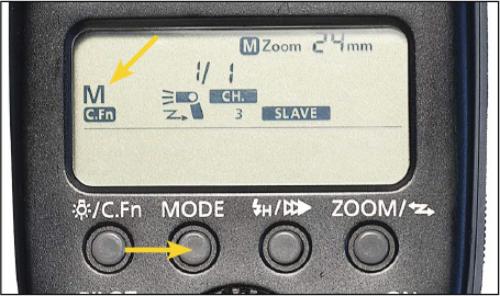
Figure 12.9 600EX-RT LCD as optical slave. Note: Canon Speedlites default to E-TTL mode when you activate them as slaves. The slave will change its mode when the master fires.
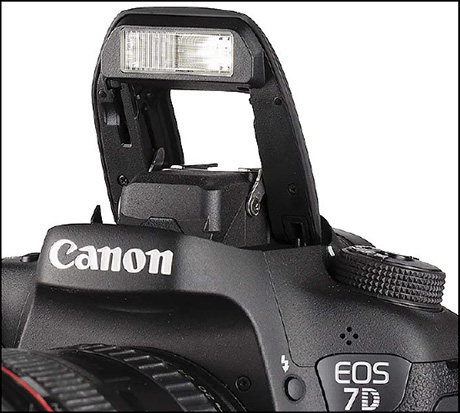
As of this writing (early 2015) there are seven EOS cameras with pop-up flashes that can serve as an optical master for off-camera Speedlites. Canon refers to this feature as the “Integrated Speedlite Transmitter.” See Figure 12.3 for the specific cameras with this feature.
Speedliter’s Tip: —The Limitations Of A Pop-Up As Master—
Shorter range
—The pop-up’s power is much less than a Speedlite, so the effective range is limited.
Narrow field in front of camera
—The pop-up flash fires straight forward. With a Speedlite as master, the head can be turned to fire towards a slave Speedlite out to the side of the camera.
No high-speed sync
—This special sync option was discussed in Chapter 7
: Control Your Speedlite
. One important use of high-speed sync is to enable the use of wide apertures (for shallow depth of field) when using fill-flash outdoors in bright sunlight. When using a pop-up flash, directly or as a master, the fastest shutter speed possible will be 1/250″.
If you have the 7D Mark II, 7D, 70D, or 60D, follow these steps to use your pop-up as an optical master:
1. Your camera must be set to either M, Av, Tv, P , or A-DEP .
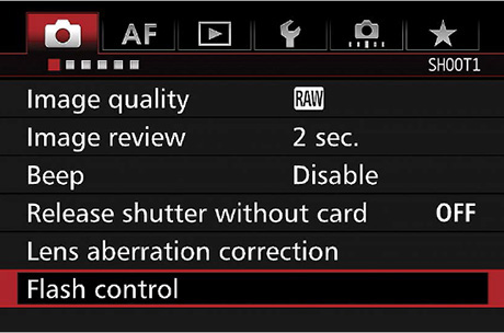
2. On the camera LCD, look for Flash Control on the first shooting menu (red camera).
3. Scroll down to Flash Control and then press the Set button.
4. Scroll down to Built-In Flash Function and then press the Set button.
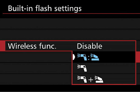
5. Scroll down to Wireless function and then press the Set button.
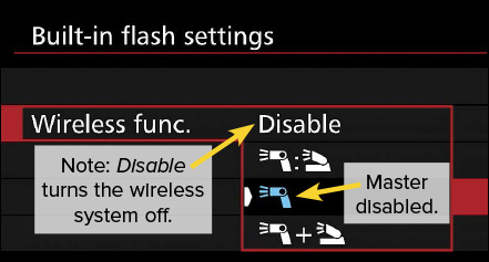
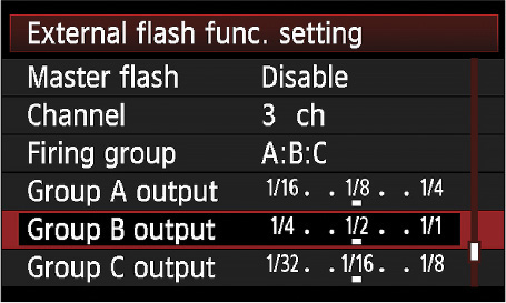
The four Wireless Function menu options, as shown top to bottom in Figure 12.12 , are:
Disable
—Allows the pop-up to fire normally without working as an optical master.
Ratio Control
—Enables the pop-up to fire at one E-TTL power level and the slave Speedlite(s) to fire at another.
Trigger Off-Camera Speedlites Only
—Enables the pop-up to be an optical master that sends instructions to the slaves and then remain dark when the shutter opens.
Trigger the Speedlite(s) with separate flash exposure from built-in flash
—Fires slave Speedlite(s) and provides fill flash from pop-up.
If you have the T6i, T5i, T4i, or T3i, follow these steps to use your pop-up as an optical master.
1. Your camera must be set to either M, Av, Tv, P , or A-DEP .
2. Raise the pop-up flash by pushing the button on the side of the camera.
3. Press the Menu button and look for Flash Control on the first shooting menu (red camera).
4. Scroll down to Flash Control and then press the Set button.
5. Scroll down to Built-In Flash Function and then press the Set button.
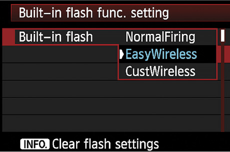
The Built-in Flash menu options, as shown top to bottom in Figure 12.13 , are:
NormalFiring
—allows the pop-up to fire normally without working as a master.
EasyWireless
—all external Speedlites will fire in E-TTL at the same power level (regardless of Group assignment). FEC may be used with EasyWireless. The pop-up master will send the instructions and then remain dark when the shutter opens (to avoid the look of on-camera flash).
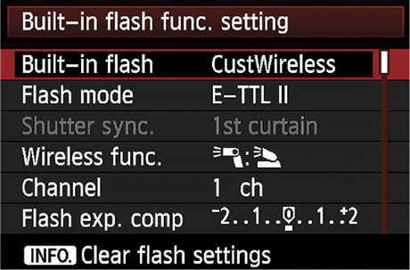
CustWireless
—allows you to customize the set-up of the wireless system. There are four CustWireless menu options (same as those shown in Figure 12.12
). They are:
 Disable
—allows the pop-up to fire normally without working as an optical master.
Disable
—allows the pop-up to fire normally without working as an optical master.
Ratio Control
—enables the pop-up to fire at one E-TTL power level and the slave Speedlite(s) to fire at another.
Trigger Off-Camera Speedlites Only
—enables the pop-up to be an optical master that sends instructions to the slaves and then remain dark when the shutter opens.
Trigger the Speedlite(s) with separate flash exposure from built-in flash
—fires slave Speedlite(s) and provides fill flash from pop-up.
Note: The 600EX-RT is capable of working in optical or radio wireless. It cannot do both at the same time. These steps pertain to optical wireless only. See Chapter 13 : Radio Speedliting: Canon’s New Frontier for the details on radio Speedliting.
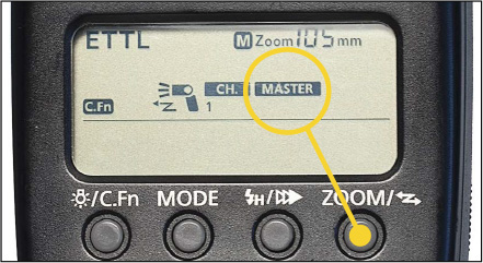
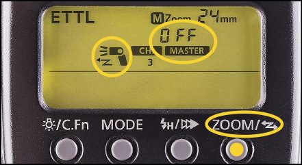
Repeatedly press the Wireless Flash Button (button on left with sideways flash-bolt icon) until the optical wireless icon appears in the upper-right corner of the Speedlite LCD and the word “Master” appears—as shown in Figure 12.15
.
1. Press and hold the Zoom button for three seconds.
2. If OFF is blinking, turn the Select Dial right one click so that Master ON blinks. If Slave ON is blinking, turn the Select Dial left one click. Press the Set button to confirm your choice.
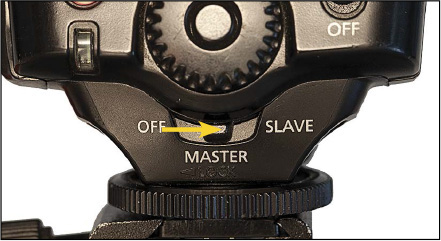
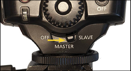
Move the switch below the Select Wheel from Off to Master.
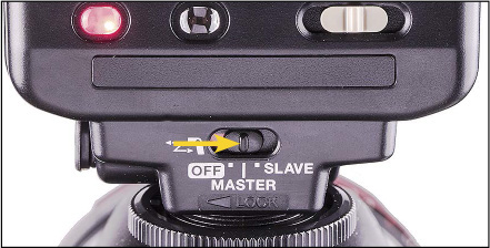
Move the wireless switch from Off to Master.
As shown in Figure 12.3 , there are four Canon flashes that can serve as optical masters that also have the capability of being controlled on a camera’s LCD. They are:
600EX-RT
580EX II
90EX
MR-14EX II
The way that the menu for these flashes appears on the LCD depends upon the camera. The early camera-based Speedlite menus use a list of text prompts that must be scrolled vertically. Newer cameras use icons backed up by text prompts.
1. Press Menu on the camera to activate the LCD monitor.
2. Find “External Speedlite control,” “Flash control,” or a similar command and press the Set button.
3. Select “Flash function settings” or similar and press the Set button.
4. Scroll down to Wireless set or similar and press the Set button.
5. Select Enable in Wireless func. and press the Set button.
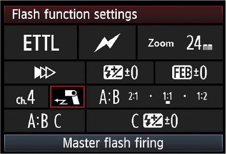
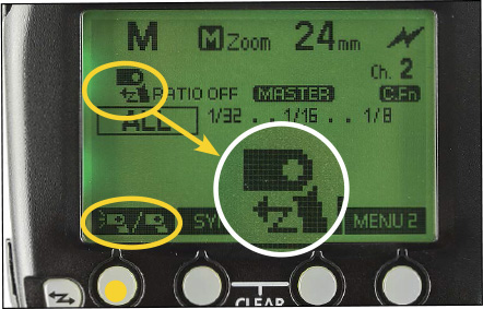
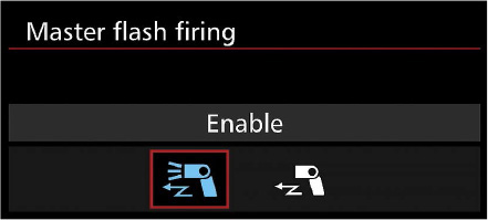
Figure 12.20 Newer camera models have icon-based menu systems that show all the current Speedlite settings on a single screen. Here, the icon in the red box indicates that the master has been disabled—it will send instructions to the slave via an optical pre-flash and then remain dark when the shutter opens.
1. Press Menu on the camera to activate the LCD monitor.
2. Find “External Speedlite control,” “Flash control,” or a similar command and press the Set button.
3. Select “Flash function settings” or similar and press the Set button.
4. Scroll through the options until “Master flash firing” is highlighted (as shown in Figure 12.20 ) and press the Set button.
5. Select “Enable” or “Disable” as desired and press the Set button.
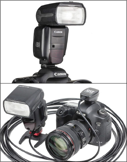
A master Speedlite must be connected to the camera’s hotshoe—either directly or via an E-TTL cord. Use a short E-TTL cord if your master is bolted to a flash bracket, such as that shown previously in Figure 12.4 . Use a straight, extra-long E-TTL cord if you want to move the master Speedlite farther off-camera. There are several reasons for making this move.
Figure 12.21 An optical master Speedlite can either be connected directly to the camera’s hotshoe (top) or to the hotshoe via an E-TTL cord (bottom).
The sensors on optical slaves are blinded when they look into the sun (just like us). You can use an extra-long E-TTL cord to move the master Speedlite to a spot where the slaves can look away from the sun and see the master’s signals. Remember, of course, to turn the bodies of the slave to look at the master and their heads so that they point towards your subject.
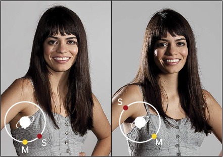
As we explored in Chapter 5 : Position Is Relative , there is a significant difference between the look of on-camera flash versus off-camera flash—remember, it’s the shadows that make the difference.
Figure 12.22 Left: The on-camera master (M) provides fill light and the slave (S) provides key light. Right: When the master (M) is moved off-camera as the key light, the slave (S) can be moved to create hair and rim light.
When you have an optical master sitting in the hotshoe of your camera, it will add on-camera flash to your shot. This is fine if you need a bit of fill light (use ratios to dial the master’s power down separately from the slave’s power). As will be discussed later in this chapter, you can also disable the master so that it sends instructions to the slaves and then remains dark when the shutter opens. When you do this, you essentially have a $400+ communicator on top of your camera.
For the cost of the extra-long E-TTL cord ($45–$65), you can bring the master back into the mix as either an off-camera key or fill light. Just move it to a spot where it contributes valuable light to the shot and has a visual path to each of the slaves. Remember to keep it enabled so that it sends the instructions to the slaves and fires when the shutter opens.
I learned this technique from my sensei, Joe McNally, who links several Nikon off-camera cords together to fire a master Speedlight out a window so that it will control several slaves outside (which usually send gelled light back in through the window to mimic a sunset). This was the genesis for my idea to use an extra-long E-TTL cord—stringing a bunch of short coiled cords together is more expensive.
As Canonistas, we can control the entire system from the LCD of our cameras. The E-TTL cord enables us to change the wireless system’s mode, sync, power, etc., from our shooting position.
Figure 12.23 Top: An optical master on an extra-long E-TTL can be moved to a window to control gelled slaves outside. Bottom: The resulting effect is that of a setting sun streaming in through the window.
You will see a number of my shots that were inspired by Joe’s technique later in the Handbook . For now, know that a long, straight E-TTL cord is much easier to manage than three coiled cords attached end-to-end. The coiled cords want to swing in the air between the camera and Speedlite. A long, straight cord will drop to the floor and stay out of the way. I have even been able to hide the cord and master in frame because of its length and flexibility.
When we get into Chapter 15 : Those Big Modifiers Always Get In The Way , you will learn how softboxes and other large modifiers create soft shadows. One of the challenges of using a large modifier is that its shape can block the visual path between an optical master and slave.
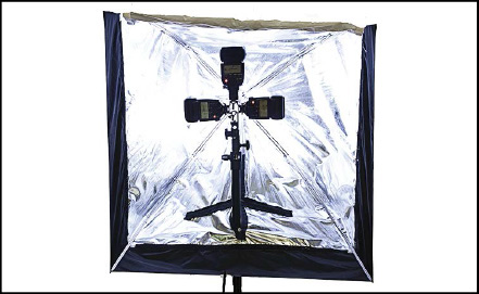
Figure 12.24 The Apollo softboxes by Westcott mount the Speedlite(s) inside. By connecting the master Speedlite to an extra-long E-TTL cord, you can control the wireless system from your camera.
This might not be an issue indoors—where the master’s signal can reach around the softbox by bouncing off a wall. When there are no surfaces for the bounce—such as when shooting outdoors—an extra-long E-TTL cord can be used to control the master Speedlite while it is attached to the softbox. The master’s light coming out of the softbox can be used to control nearby slave Speedlites—provided that they are not hidden behind another modifier.
Some of my favorite softboxes for Speedliting are the Apollo softboxes made by Westcott. Rather than mount the Speedlite outside, the Apollo design mounts the flash inside. The size of the Apollo softboxes also makes it possible to mount several Speedlites inside, which is a big help when shooting high-speed sync (which causes a power loss) or when a faster recycle time is needed.
With Canon’s ability to control the settings of a master Speedlite from the LCD of the camera, moving that master inside an Apollo on an E-TTL cord and letting it control slaves is a fantastic way to work. I’ve done this for years.
One of the issues you have to consider when setting up a wireless shoot is whether the master is enabled or disabled . By enabled , I mean that it will send instructions to the slaves as well as fire during the actual exposure. By disabled , I mean that it will communicate with the slaves, but not fire when the shutter is open.
This can get confusing, so I’ll say it up front: Even if you disable an optical master, you will see it flash. What you’re seeing is the master communicating to the slaves via a series of pre-flashes right before the actual exposure. As you know, the difference between the pre-flash and the main flash is a fraction of a second.
If the master is in the hotshoe, you run the risk of killing the quality of light with on-camera flash if it fires at a powerful level. A strong blast from the master will make your picture look like a driver’s license portrait.
If you are shooting a two-light setup—namely a master and a slave—then you have a legitimate reason to want light from the master. If the master is on-camera (as opposed to being moved off-camera with an E-TTL cord), you’ll want to use the master as a low-power fill.
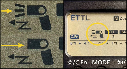
It takes really keen eyesight to see the master enabled icon on the Speedlite LCD panel. What you are looking for is whether or not there are three rays (lines) coming from the head of the miniscule Speedlite icon. If you see the three rays, you know the master is enabled. If you don’t see the three rays, either the master is disabled or you need to find your reading glasses.
Figure 12.25 The rays in the top-left frame indicate that the master is enabled. The absence of the rays in the bottom-left frame indicate that it is disabled. At right is the icon on the LCD of a 580EX II.
1. Confirm that your Speedlite is set as an optical master.
2. Repeatedly press Fn Button 4 (rightmost) until Menu 2 displays.
3. Press Fn Button 1 (leftmost) to set Master Flash Firing to Enabled or Disabled. You have to look at the tiny Speedlite icon on screen: Enabled = light rays present.
1. Repeatedly press the Zoom button to cycle through the wireless master options until you see the three rays blinking on the Speedlite icon.
2. The word Off or On will also blink with the three rays.
3. Turn the Select Dial if you need to choose the other option.
4. Press the Set button to confirm your choice.
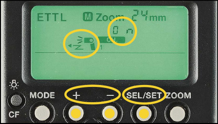
1. Confirm that the Speedlite is a master.
2. Press the Sel/Set button repeatedly until the Speedlite icon blinks on the LCD.
3. Press the + or – button to set either On (Enabled) or Off (Disabled).
4. Press the Sel/Set button to confirm.
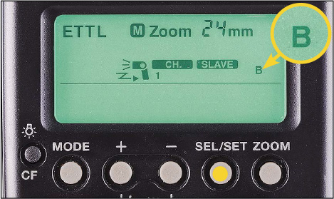
Note: The flash arrow will blink when the master is disabled.
1. Press Menu on the camera to activate the LCD monitor.
2. Scroll to “Flash Control” under the left camera tab and press the Set button.
3. Scroll down to “Built-in flash func. setting” and press the Set button.
4. Scroll down to “Wireless Func.” and press the Set button.
5. For Speedlite only, choose the icon without the pop-up (shown in Figure 12.29 ). Press the Set button to confirm.
1. Find “External Speedlite control,” “Flash control,” or similar and press Set button.
2. Select “Flash function settings” or a similar command and press the Set button.
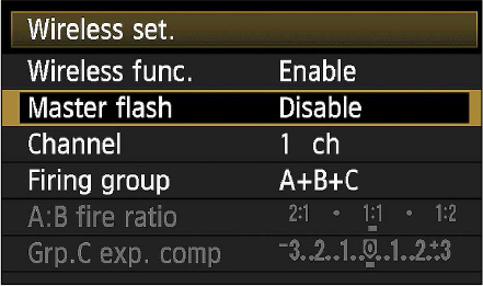
3. Scroll down to “Wireless set.”
4. Scroll down to Master flash and press the Set button.
5. Scroll up or down between Enable and Disable. Press the Set button to confirm.
Note: These are generic instructions.
Repeatedly press the Wireless Flash Button (button on left with sideways flash-bolt icon) until the optical wireless icon appears in the upper-right corner of the Speedlite LCD and the word “Slave” appears—as shown in Figure 12.25
.
1. Press and hold the Zoom button for three seconds.
2. If OFF is blinking, turn the Select Dial right two clicks. If Master ON is blinking, turn the Select Dial right one click. Press the Set button.
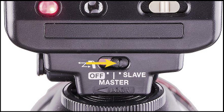
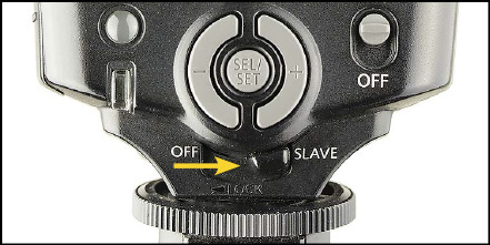
Move the switch below the Select Wheel from Off to Slave.
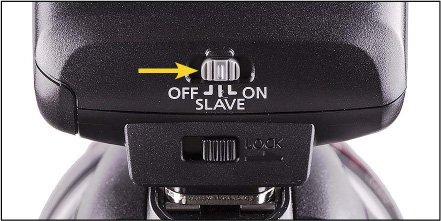
Slide the power switch from Off to Slave.
1. Press and hold the Zoom button for three seconds.
2. Press the right Select button until Slave appears in the LCD panel. Press the Set button to confirm your selection.
Move the switch below the Select Buttons from Off to Slave.
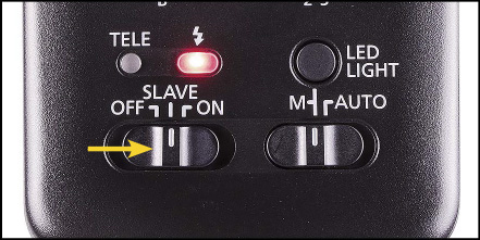
Slide the power switch to the mark between Off and On.
Slide the power switch to the mark between Off and On.
Speedliter’s Tip: —Turn Power Saving Off—
600EX-RT: C.Fn-01 set to 1–Off
580EX II: C.Fn-01 set to 1–Disabled
580EX: C.Fn-14 set to 1–Off
550EX: Do not set power switch to SE.
430EX II: C.Fn-01 set to 1–Disabled
430EX: C.Fn-01 set to 1–Off
320EX: C.Fn-01 set to 1–Off
600EX-RT: C.Fn-10 set to 0–60 minutes
580EX II: C.Fn-10 set to 0–60 minutes
580EX: C.Fn-4 set to 0–60 minutes
550EX: Do not set power switch to SE.
430EX II: C.Fn-10 set to 0–60 minutes
430EX: C.Fn-02 set to 0–60 minutes
320EX: C.Fn-10 set to 0–60 minutes
Geek Speak: —Master / Slave Ready Lights—
There are four channels in the Canon optical wireless system, simply numbered 1–4. All the Speedlites, both master and slave(s), have to be on the same channel. If your master is on Channel 3 and your slaves are on Channel 4, the slaves will not fire.
Essentially, the purpose of channels is to facilitate a way for up to four Canon shooters to shoot wireless flash in the same area. If you are working in the vicinity of other Canon photographers, introduce yourself and sort out what channel each of you will use. As long as you are on separate channels, you will not interfere with each other’s lighting.
1. Confirm that the 600EX-RT is set as an optical master.
2. On Menu 3, press the CH button.
3. Turn the Select Dial to 1, 2, 3, or 4.
4. Press the Set button to confirm.
1. Confirm that the 600EX-RT is set as an optical slave.
2. On Menu 2, press the CH button.
3. Turn the Select Dial to 1, 2, 3, or 4.
4. Press the Set button to confirm.
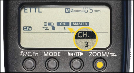
1. Confirm that the 580EX II is in master or slave mode.
2. Repeatedly press the Zoom button to cycle through until CH blinks.
3. Turn the Select Dial to 1, 2, 3, or 4.
4. Press the Set button to confirm.
1. Confirm that the wireless switch is set to either Master or Slave.
2. Repeatedly press the Sel/Set button to cycle through until CH blinks.
3. Press the + or – button to select channel 1, 2, 3, or 4.
4. Press the Sel/Set button to confirm.
1. Confirm that the 430EX II is in slave mode.
2. Repeatedly press the Zoom button until CH blinks on screen.
3. Press the + or – button to select channel 1, 2, 3, or 4.
4. Press the Sel/Set button to confirm.
Slide the CH switch to the desired channel 1, 2, 3, or 4.
The 270EX II works on all channels. There is no need to set a specific channel.
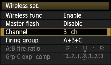
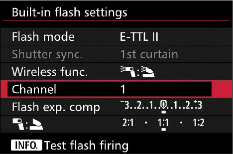
1. Press Menu on the camera to activate the LCD monitor.
2. Find “External Speedlite control,” “Flash control,” or a similar command and press the Set button.
3. Select “Flash function settings” or similar and press the Set button.
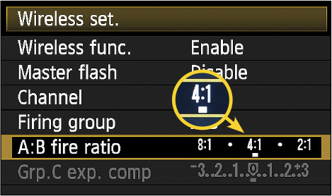
4. Scroll down to “Wireless set.” or similar and press the Set button.
5. Scroll down to “Channel” and press the Set button.
6. Use the Select Wheel to choose the desired channel (1–4). Then press the Set button to confirm your choice.
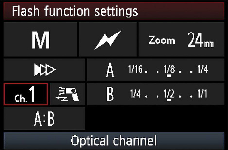
1. Press Menu on the camera to activate the LCD monitor.
2. Find “External Speedlite control,” “Flash control,” or a similar command and press the Set button.
3. Select “Flash function settings” or similar and press the Set button.
4. Scroll through the icons on screen until “Optical channel” is selected. Then press the Set button.
5. Use the Select Wheel to choose the desired channel (1–4). Then press the Set button to confirm your choice.
1. Press the flash-bolt button on the camera to pop up the built-in flash.
2. Press Menu on the camera to activate the LCD monitor.
3. Scroll to “Flash Control” under the left camera tab and press the Set button.
4. Scroll down to “Built-in flash func. setting” and press the Set button.
5. Scroll down to Channel and press the Set button.
6. Scroll up or down to the channel of your choice. Press the Set button to confirm your choice.
One of the benefits of shooting Canon’s optical wireless system is that you can control multiple Speedlites at different power levels. For instance, you can use Speedlites in two different groups so that you can adjust the amount of key and fill light wirelessly from your camera. In another situation, you might want to adjust the power levels separately for the key light hitting your subject and the background light.
Any time that you want Speedlites to operate at different power levels, you assign them to different groups. Canon calls them Flash Groups or Slave ID groups.
The Canon optical system has three Flash Groups: A, B, and C. By default, the master is always a member of group A. You will never make a Flash Group setting on the master. (Do not confuse this with the need to make a Ratio setting on the master.) Optical slaves can be in A, B, or C...but don’t stop reading right here.
Canon’s method of controlling an E-TTL group C is a bit of a workaround. I recommend that, when shooting E-TTL, you use groups A and B and avoid a group C. When shooting all the Speedlites wirelessly in Manual, then group C is as easy to run as groups A and B.
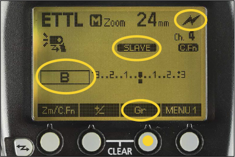
1. Confirm that the 600EX-RT is set as an optical slave.
2. On Menu 1, repeatedly press the Gr button until the desired group appears on screen.
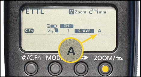
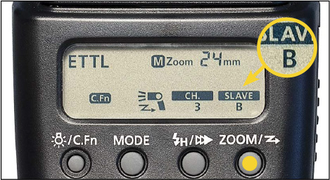
1. Confirm that the 580EX II is in slave mode.
2. Repeatedly press the Zoom button to cycle through until A, B, or C blinks to the right of SLAVE.
3. Turn the Select Dial to choose the desired group.
4. Press the Set button to confirm your choice.
1. Confirm that the switch under the Select Dial is set to Slave.
2. Repeatedly press the Zoom button to cycle through until SLAVE blinks.
3. Turn the Select Dial to change to A, B, or C.
4. Press the Set button to confirm your choice.
1. Confirm that the wireless switch is set to Slave.
2. Repeatedly press the Sel/Set button to cycle through until SLAVE blinks.
3. Press the + or – button to select group A, B, or C.
4. Press the Sel/Set button to confirm.
1. Confirm that the 430EX II is in slave mode.
2. Repeatedly press the Zoom button to cycle through until A, B, or C blinks to the right of SLAVE.
3. Press the left or right Select button to choose the desired group.
4. Press the Set button to confirm your choice.
1. Confirm that the switch under the +/- buttons is set to Slave.
2. Repeatedly press the Zoom button to cycle through until SLAVE blinks.
3. Press the left or right Select button to choose A, B, or C.
4. Press the Set button to confirm your choice.
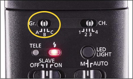
1. Confirm that the power switch is set to Slave.
2. Slide the Gr switch to the desired group A, B, or C.
The 270EX II always operates as a member of Group A.
The whole point of assigning slaved Speedlites to different groups is so you can fire them at different power levels. How you adjust the power depends upon the mode of your wireless master.
As explained in the previous section, in Canon optical wireless, the master is always a member of Group A and the slaves can be assigned to groups A, B, or C. The Flash Group setting defines how these different groups of Speedlites will work together.
ALL—fires the master and all slaves at the same power level. Even if slaves are assigned to groups B and C, they will fire as if they are members of group A.
A:B—controls the master and all slaves in group A together and all slaves in group B together. The power setting for group A can be the same or different than group B. Any slaves assigned to group C will not fire.
A:B C—provides three groups of power control in E-TTL. (In Manual and Multi wireless, the three-group setting is A:B:C.)
When you shoot E-TTL in optical wireless, you will use ratios to adjust the power level of different groups. Essentially, you use a ratio to establish the relationships between the power level of the groups and then E-TTL drives the whole power level up or down as needed—which you can fine-tune with FEC, just as you would in non-wireless E-TTL.
I understand that the idea of ratios can be confusing. Read on bravely—I am confident that you will get the concepts sorted out. However, if you continue to find Canon ratios confusing, switch your master’s mode to Manual and dial in the power setting for each group directly.
In Canon wireless, a ratio for two E-TTL groups is expressed as group A to group B (A:B). When you are looking at the ratio scale on the LCD panel of your master Speedlite or on the LCD monitor of your camera, the left side is always group A and the right side is always group B.
Understand that we’re talking about the ratio scale, not the placement of your Speedlites. You are certainly free to place the group B Speedlites on the left side of the subject and the group A Speedlites on the right side (or wherever else you want).
However, when you do this, you have to remember that if you want the left side to be brighter, you have to move the ratio farther to the right on the scale.
I like to keep things simple. So, I always try to have my Group A Speedlites on the left side and my Group B Speedlites on the right side of my subject.
I concede that Canon’s ratio approach is different and that it seems antiquated. I would rather have an FEC scale for each group—which is exactly what we now have when shooting the 600EX-RT in Group mode (radio only). Yet, Canon’s E-TTL ratios are what they are. So, I learned a long time ago to decode ratios into stops and quit whining about the jargon.
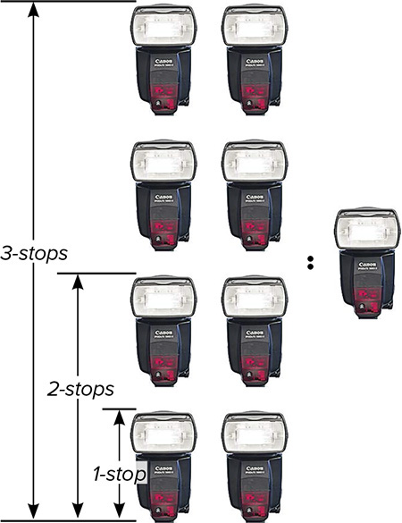
The ratio scale runs from 8:1 on the left to 1:1 in the center to 1:8 on the right. Simply stated, 8:1 means that Group A is eight times brighter than Group B. 1:1 means that they are equal. 1:8 means that Group B is eight times brighter than Group A.
Now, please, please, please don’t fall into the trap of thinking that 8:1 or 1:8 means that one side is eight stops brighter than the other. The truth is that it means one side is three stops brighter than the other. Confused? Don’t worry, we’ll go through the math slowly.
The first thing to remember when converting ratios to stops is that to change a flash or camera setting by one stop means that you have either doubled the light or cut it in half.
Now, to start with the math, if you have a 1:1 ratio, that means that the illumination from both sources is equal.
Now, if you double the illumination on the left side, you have increased it by one stop. Since we have twice as much illumination on the left side as on the right side, we have a ratio of 2:1.
Let’s increase the illumination on the left side again by exactly one stop. So what’s the new ratio? Did you say 3:1? Sorry. To increase something by a stop, you double it. So double two and you have...four. The new ratio is 4:1, which means that the left side is two stops brighter than the right side.
Final-round question: If you increase the brightness of the left side again by exactly one stop, what’s the ratio? Doubling four is easy: The new ratio is 8:1. From the beginning, how many times have we doubled the light? Three. 1→2→4→8. So 8:1 is a three-stop difference.
Note: If the ratios are 1:2, 1:4, or 1:8, then the higher power level jumps to the other side.
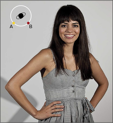
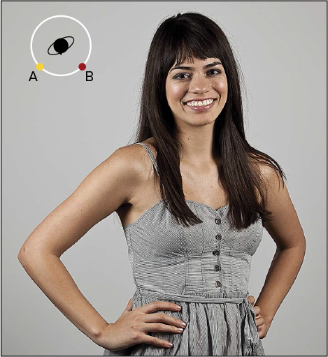
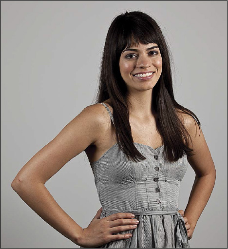
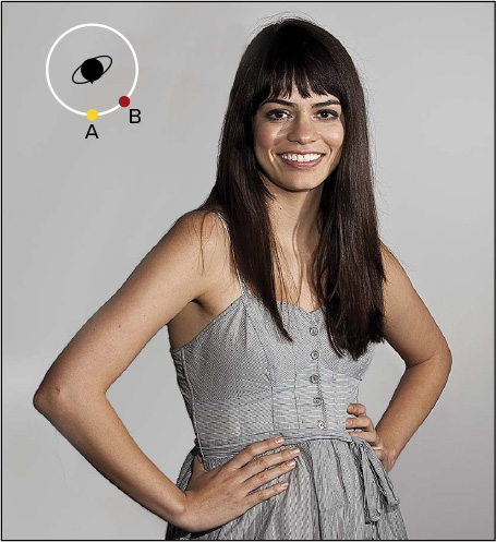
There are many ways to set up two-group lighting. On this spread, we’ll look first at a traditional setup with hard lights at the same distance from the subject and 45° on the lighting compass to the left and right of the subject. Then we’ll look at the same with soft lights.
In the hard-light series, notice how the density of the arm shadow in the lower corner increases as the ratio changes.
In the soft-light series below, notice that there is no arm shadow because the softbox was able to reach around Mallory.
If the master is on-camera (as opposed to being moved off-camera via an E-TTL cord), I will almost always disable it so that it does not add a bunch of unflattering on-camera flash to the scene. The only time that I will not disable the on-camera master is when I’m using it to create on-axis fill light.
In these examples, the off-camera key light (Group B) is at 45° right on the lighting compass and the same distance from the subject as the on-camera master/fill flash (Group A).
Interesting light happens when the subject is caught in the crossfire between two lights that are facing each other. (Trade secret: This is one of my favorite lighting setups.) In these shots, the key (group A) is at 45° right on the lighting compass and the rim (group B) is at 135° left.
This means that the key light is in front of the subject and the rim light is behind. Both are equidistant from the subject.
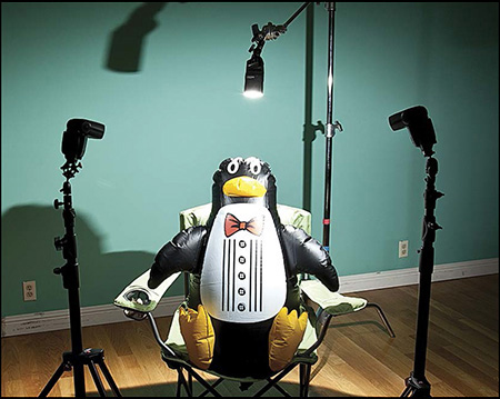
Placing your Speedlites into three groups can provide you with the traditional key, fill, and background lights. If used a bit more boldly, it can also provide you with key, fill, and rim light.
Canon’s view of three-group E-TTL setups is very specific. Groups A and B light the subject. Group C lights the background.
Figure 12.71 My homage to the infamous three-group lighting diagram in the 580EX II user manual—group A is 45° left, group B is 45° right, and group C is on the background. Note: Use of a penguin is optional.
In three-group E-TTL, groups A and B are still controlled through an A:B Ratio. Group C is controlled via a special group C Flash Exposure Compensation. A simple way to think about controlling the C group is that if you want it brighter, you dial up its FEC (and vice versa).
There are three ways to set Group C in E-TTL:
On the camera LCD monitor (best option)
On the master Speedlite LCD panel
On the Group C Speedlite(s)
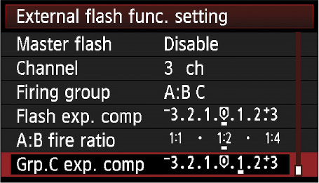
If the master is a 600EX-RT or a 580EX II on a compatible (40D or later) camera, the easiest place to control three-group E-TTL is on the camera’s LCD.
Figure 12.72 If you have a 580EX II as the master, setting the FEC for group C is much easier on the camera’s LCD.
1. Confirm that your Speedlite is an optical master and that the mode is E-TTL.
2. Press the rightmost function button repeatedly until its label reads “Menu 2.”
3. Press the Ratio button repeatedly until you see A:B in one box and C just below.
4. Press the Gr button. A:B will highlight. If you want to adjust the A:B ratio, do step 5. If not, jump straight to step 6.
5. To set the A:B ratio, press the A:B +/- button to activate the ratio scale. Use the Select Dial to choose the ratio. Press the Set button. Press the return arrow.
6. To adjust the group C FEC, press the Gr button, turn the Select Dial to highlight C, and press the Set button to activate the FEC scale. Then press the C +/- button to highlight the FEC scale. Use the Select Dial to choose the amount of FEC. Press the Set button. Press the return arrow.
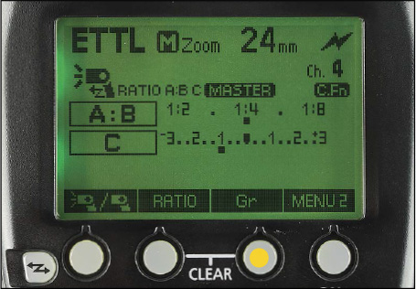
1. Confirm that your Speedlite is an optical master and that the mode is E-TTL.
2. Press the Zoom button to cycle through the choices. When Ratio blinks, turn the Select Dial so that A:B C appears. Press the Set button.
3. Turn the Select Dial to the desired A:B ratio. Press the Set button.
4. Press the Set button four times. It will cycle through FEC, FEB, A:B Ratio, and then Ratio C. You are looking for “Ratio C” to blink.
5. Turn the Select Dial to the desired FEC for Group C. Press the Set button.
Figure 12.74 Step 5—After the ratio mode on the Speedlite is set to A:B C, you first set the A:B ratio as you would for a two-group setup. The key to setting the FEC for group C is to push the Set button four times.
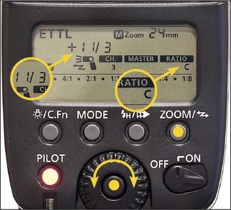
This can be much faster than setting the Group via the master. However, you have to walk over to the Group C slave(s) and do it by hand. The following works for the 580EX II, 580 EX, 430 EX II, 430 EX:
1. Confirm that the Speedlite is in slave mode and set for Group C.
2.
Press the Set button. You will see the FEC icon blink.
3. Turn the Select Dial until the desired amount of Group C FEC appears.
4. Press the Set button.
Figure 12.75 If you don’t mind taking a walk, an easy way to set the FEC for group C is to do it manually on each group C speedlite—the same way that you would normally dial in FEC by turning the Select Dial and then hitting the Set button.
Compared to E-TTL, Manual mode is a much easier way to control a multi-group Canon wireless system. Manual gives you the ability to adjust the power of each flash group individually.
If your subject-to-flash distance is fixed, such as when shooting a portrait, then I suggest that you switch the master’s mode to Manual. Remember that this mode change will be made on the slave(s) when the master next fires. You do not need to set the slaves to Manual.
If you need just one group, set the Flash Group to ALL. If you need two groups operating at different power levels, use A:B. If you need three groups of control, use A:B:C.
An important bit to remember about Manual mode in optical wireless is that the master’s instructions are still sent to the slaves via a coded series of pre-flashes. So, flashes and strobes that use optical slave eyes as triggers will still fire prematurely. (This is not a problem when shooting Manual mode in radio wireless as the master’s instructions are sent to the slaves invisibly by radio.)
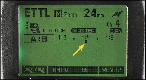
If the master is a 600EX-RT or a 580EX II on a compatible (40D or later) camera, the easiest place to control manual power settings for optical wireless setups is on the camera’s LCD.
1. Confirm that your Speedlite is an optical master and that the mode is Manual.
2. On Menu 1, press the Ratio button repeatedly to set the number of groups—ALL (one group), A B (two groups) or A B C (three groups). Press the Set button to confirm.
3. Press the Gr button to select the group you want to control. At first, A (or ALL) will highlight. If you want to adjust the group A power, press the A +/- button to highlight the power scale. Use the Select Dial to choose the power level. Press the Set button to confirm. Press the return arrow.
4. To choose another group to change, press the Gr button again. The last group that you worked with will be highlighted. Use the Select Dial to highlight the letter of the next group that you want to control. Press the +/- button for that group. The power scale will highlight. Use the Select Dial to choose the power level. Pres the Set button to confirm. Press the return arrow.
5. To work a third group, repeat step four.
1. Confirm that your Speedlite is an optical master and that the mode is Manual.
2. Press the Zoom button repeatedly until Ratio blinks.
3. Turn the Select Dial to choose either Off (one group), A:B (two groups), or A:B:C (three groups). Press the Set button to confirm your choice.
4. Turn the Select Dial so that A is underlined. Press the Set button. A and its power setting will now start blinking.
5. Turn the Select Dial to the power level you want for group A. Press the Set button to confirm your choice.
6. B and its power level will now blink. Turn the Select Dial to the power level you want for Group B. Press the Set button to confirm your choice.
7. If you are in A:B:C, C and its power level will now blink. Turn the Select Dial to the power level you want for Group C. Press the Set button to confirm your choice.
8. Keep in mind that the master is always part of Group A. If you do not want it to flash, you must disable it.
Note: After you complete the settings, you can check the respective flash output for each group by turning the Select Dial.
1. Confirm that your Speedlite is an optical master and that the mode is Manual.
2. Press the Sel/Set button repeatedly until Ratio blinks.
3. Press the – (minus) button to choose either Off (one group), A:B (two groups), or A:B:C (three groups). Press the Sel/Set button to confirm your choice.
4. A and its power setting will now start blinking. Press the + or – button to select the power for group A. Press the Sel/Set button to confirm your choice.
5. B and its power setting will now start blinking. Press the + or – button to select the power for group B. Press the Sel/Set button to confirm your choice.
6. If you are in A:B:C, C and its power level will now blink. Press the + or – button to select the power for group C. Press the Sel/Set button to confirm your choice.
7. Keep in mind that the master is always part of Group A. If you do not want it to flash, you must disable it.
Note: After you complete the settings, you can check the respective flash output for each group by pressing the + or – button.
If you become obsessed with stroboscopic flash, you will want to check out the options for slave groups in Multi mode. In wireless Multi, the total number of flashes and the Hertz (flashes per second) is set for the entire system and power is set by group.
Essentially, it works the same way as Manual mode. If you need just one group, set the Flash Group to ALL. If you need two groups operating at different power levels, use A:B. If you need three groups of control, use A:B:C. Follow the preceding instructions for the model of your master when in Manual mode and you will be on your way. Just remember to set the mode of the master to Multi in step 1.
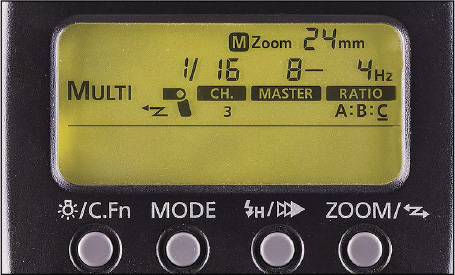
Figure 12.80 On the 600EX-RT, Menu 2 is the gateway in radio wireless to controlling multiple groups of Speedlites in Multi mode.
Figure 12.81 The LCD of 580EX II in Multi mode wireless with three groups. Here C is underlined, indicating that its power level can be changed.
There is a little-known technique in Canon optical wireless that sets up a Speedlite as an Independent Slave. While this technique may not be widely known, it is incredibly useful in several situations:
You want to shoot three-group E-TTL (A:B C), but find the FEC control of the group C flashes to be cumbersome.
You want to have more than three groups in your wireless set-up.
You want to shoot Manual and Multi modes together.
You want to use the ST-E2 optical transmitter with slaves in Manual mode.
Essentially, an Independent Slave is one that fires when the master fires all the other slaves, but its power level and mode are set directly on the unit. You can use either Manual or Multi as the mode on an Independent Slave.
There is nothing you do on the master to shoot Independent Slaves. You just have to activate the Speedlites as Independent Slaves, set their mode, and adjust their power. You can use any number of Independent Slaves—each at their own power level. Further, you can use any wireless mode and ratio set-up that you desire on the master.
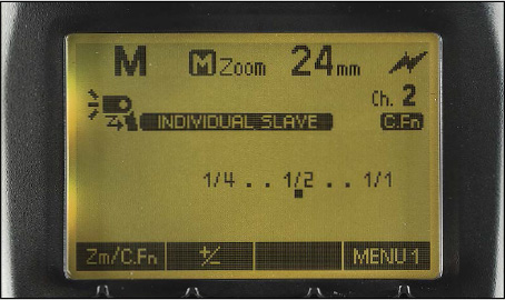
1. Confirm that the Speedlite is set as an optical slave and that its channel matches that of the master.
2. Hold the Mode button down until you see “Individual Slave” appear on the LCD. This takes about three seconds.
3. The default mode for an Individual Slave is Manual. To set the power for Manual mode, press the +/- button on Menu 1 to highlight the power scale. Use the Select Dial to choose the power level. Then press the +/- button or the Set button to confirm your choice.
4. If you want the Independent Slave to work in Multi, after step 2, press the Mode button and Multi will appear on the LCD. Then press Menu 2 to access the three settings needed by a stroboscopic flash: power level, total flashes, and flashes per second (Hertz).
To return to normal slave operation, press the Mode button once or twice so that E-TTL appears in the upper left corner of the LCD.
1. Confirm that the Speedlite is set as an optical slave and that its channel matches that of the master.
2. Hold down the Mode button until the M blinks on the left side of the LCD panel. Press the Set button.
3. The default mode for an Individual Slave is Manual. The M and the power level indicator will blink to indicate that the power level can be changed. If you pause, the power level will stop blinking. To reactivate the selection option, press the Set button again. To change the power, turn the Select Dial to the level you want. Press the Set button. The power level will lock, and the M will keep blinking.
4. If you want the Individual Slave to work in Multi (500-series only), after step 2, press the Mode button and Multi will appear on the LCD. Press the Set button and the Select Dial to access the three settings needed by a stroboscopic flash: Hertz, number of flashes, and power.
To return to normal slave operation, press the Mode button once or twice so that E-TTL appears in the upper left corner of the LCD.