Soil is loose surface material. Rock is the hard crust of the earth, which underlies and often projects through the soil cover. There is no clear distinction between soil and rock. Geologically, all soils are considered to be rock formations. In ordinary usage, rock is something hard, firm, and stable.
A contractor’s definition is that rock is any material which cannot be dug or loosened by available machinery, but this distinction from soil may depend more on the power, size, and digging efficiency of the machinery than on the material itself.
Material to be excavated can also be roughly divided into three classes: rock, hard digging, and easy digging.
Rock is anything that needs blasting or ripping for efficient digging by most machines. Hard digging is compacted, cemented, or rocky dirt, clay, soft shale, and rotten rock, that can be dug directly by heavy machinery, or loosened readily by rippers. Easy to medium digging is any soft or fine, firm or loose deposit.
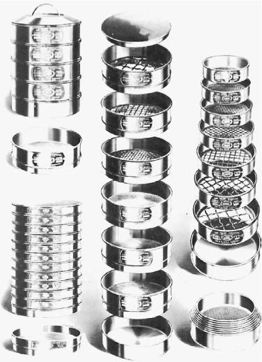
Soil. Soil is composed of particles of various sizes and chemical compositions. It can be analyzed as to sizes by sifting a dried and weighed sample through a set of testing sieves, such as are shown in Fig. 3.1, and weighing the material retained on each screen.
If further analysis is required for particles passing the smallest (200-mesh) sieve, it is done by hydrometer. This process is based on the fact that the speed of settlement of such particles is proportional to their size.
Figure 3.2A indicates the size particles which are included in the common soil classifications. There are several scales, in which the boundaries between different classes may vary. The differences among them are not important to the average contractor. Figure 3.2B shows another means of classifying soils.
A plastic soil is one which can be rolled as between the hands, into strings ⅛ inch (0.32 cm) in diameter without falling apart. Plasticity is a function of soil character and of moisture content. The minimum amount of water in terms of percent of oven-dry weight of the soil which will make it plastic is defined as the plastic limit of the soil. If no amount of water will allow it to roll into strings, it is called nonplastic, with the symbol NP.
The liquid limit is minimum moisture content, in terms of percent of oven-dry weight, which will cause the soil to flow if jarred slightly.
The plasticity index is the difference between the plastic limit and the liquid limit; that is to say, the range of moisture content in which the soil is plastic.
Soils or other particles may also be classified as to grain shape or hardness, and mineral and organic content. These factors will affect their resistance to weather, stability under load, wear on digging parts, and internal friction.
FIGURE 3.1 Testing sieves. (Courtesy of W. S. Tyler Co.)
Most soils are inorganic, and are made up of products of decay and breaking up of rock. Organic soils and organic material in soils are largely humus, which is formed by decay of vegetation and has no definite particle size. Organic materials may also consist of lime from shells or from limestone originally formed from shells, and animal bones and excrements.
Rock. Geologically, rocks are classified as to the way in which they were made. Those which solidified out of a molten state are called igneous, and are subdivided into volcanics cooled at the surface, and plutonic hardened deep underground.
Sedimentary rocks are built up of soil or plant or animal remains and have been hardened by pressure, time, and depositing of natural cements.
Metamorphic rocks were originally igneous or sedimentary, but have been altered by extreme heat and pressure.
FIGURE 3.2A Soil classification.
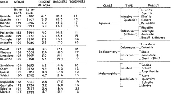
Figure 3.3 contains tables classifying rocks as to type and hardness. The latter quality is quite variable, even in one formation, and may be made up of different factors, as resistance to penetration, abrasion, or crushing.
Digging Resistance. The resistance which must be overcome to dig a formation will be made up largely of hardness, coarseness, friction, adhesion, cohesion, and weight.
In digging, hardness is resistance to penetration. It is increased by close packing of soil, or filling of voids with finer particles, or lime or other natural cements. Clay soils are hard when dry, and soft when wet.
FIGURE 3.2B Classification of soils and soil-aggregate mixtures. (Courtesy of Portland Cement Association.)
Cobbles, boulders, or hard lumps increase the power requirement for penetration. They are most troublesome when they are oversize for the machine, or packed so firmly in place that they cannot slide or rotate away from the cutting edge.
As the digging edge penetrates, friction absorbs an increasing proportion of its force. It is affected by particle size and hardness, by the amount of moisture, and the presence or absence of natural lubricants such as humus or soft clay.
Adhesion is the sticking of soil to the digging parts. It may increase the friction load substantially in wet work.
Cohesion is resistance to tearing apart. Firm or hard materials may split readily along bedding or cleavage planes so that they can be dug rather easily from the proper direction. Relatively soft clay banks may be very difficult to dig because of strong and uniform cohesion. A tough formation lacking planes of weakness is described as “tight.”
Rippability. This is a measure of the ease or difficulty with which a rock can be broken by heavy rippers into pieces that can be economically moved by other equipment, usually scrapers.
At least three factors are involved: resistance to breakage of the rock material itself, the extent to which it is weakened by bedding layers (lamination) or by joint cracks or fault movement, and the degree to which the rock has been softened and weakened by weathering.
Many rocks are readily rippable at the surface, but become increasingly resistant with depth because of less exposure to weathering. A generally rippable rock may contain seams or boulders that are difficult or impossible to rip.
Some rocks are nonrippable in their natural condition, but can be ripped after shaking up by light blasting.
In general the igneous rocks such as basalt, granite, diorite, felsite, and lava are not rippable unless they are greatly weakened by weathering. They do not respond well to light blasting unless they have a closely jointed structure.
Massive metamorphic rocks such as gneiss, marble, and quartzite are usually nonrippable, but slate and thinly bedded schist can be ripped.
Some rocks have an absolute resistance to ripping. That is, they cannot be shattered by any amount of pressure that can be exerted by a ripper tooth. More often, rippability is determined by how much force can be applied. Limitations are the strength of teeth and shanks, the power available, and the economics of applying the power.
There are also rocks that will break or tear rather readily, but remain in such large pieces that they cannot be handled economically. Oversize is sometimes broken by walking the ripper-tractor on chunks, by a crane or drop ball, or by blasting.
Ripping is usually not economical unless the product is fine enough for efficient scraper loading, or can be made so by secondary work.
Seismic methods may be used. Rippable rocks seem to carry vibration differently from nonrippable formations, as indicated in Fig. 3.4A.
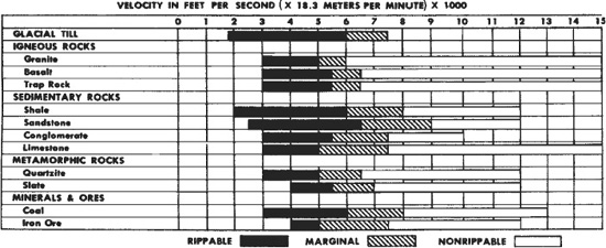
FIGURE 3.4A Rippability and seismic vibration.
FIGURE 3.4B Seismic recorder and readings.
Seismic testing is the recognized method of testing rippability. It depends on the relationship between the cohesiveness of rock and the speed of vibration through it.
A diagram of the method used is shown in Fig. 3.4B.
Rock Lab for Contractors. Since rock is often a most troublesome obstacle for contractors, the Vermeer Corporation, that manufactures equipment for trenching, excavation, and directional drilling, established a rock lab in the state of Iowa in the United States.
This Rock Lab points out that standard testing procedures are not good at predicting the rock cutting likelihood. Their tests include evaluating samples for:
1. Unconfined compressive strength, as normally done on a cylinder of the rock;
2. Indirect “Brazilian” tension testing by applying pressure from the side of the cylinder to measure the force required to fracture the sample;
3. Comparing the ratio of the unconfined compressive strength to indirect tensile strength as a measure of the brittleness of the rock;
4. Abrasivity test in which weight is applied to a sharpened steel pin as it is dragged across a rock sample. The effect on the pin predicts wear that this type of rock will cause to equipment cutting tools.
Effectively predicting the performance of equipment on potential job sites can help with the determination of the equipment needs for the job to be done.
Weight. Figure 3.5 gives the approximate weights per cubic yard of various materials.
Weight may limit the amount that can be dug or carried in a bucket or body, and the speed with which the load can be hoisted or transported. It is a critical factor in selection of dragline and clamshell bucket sizes, and in regard to the length and angle of the boom that carries them.
FIGURE 3.5 Weights of materials.
Soils differ greatly in their ability to support and permit movement of vehicles. An important characteristic is the amount of friction that exists between the ground surface and the drive tires or tracks of a machine on it.
Tractive Efficiency. This is a measure of the proportion of the weight resting on drive wheels or tracks that can be converted into movement of a machine. Soil characteristics and condition are very important in determining it.
It is difficult to estimate and classify the tractive efficiency of ground surfaces, as wide variations may be caused by the shape of particles and their size gradation. In addition, the presence of certain compounds that do not show up in a soil specification may increase traction by improving packing qualities and even cementing particles together. Other substances may reduce traction by lubricating grains so that they move freely on each other and on tire surfaces. For example, salt improves packing qualities, lime acts as cement, and soapstone (serpentine, mostly H4Mg3Si2O) acts as a lubricant.
The amount of water present is an important variable. For any soil there is a certain moisture content that gives best traction. In sandy or gravelly soils, less water is likely to allow them to become loose and unsatisfactory, while more water has little effect. In fine-grained soils too little water (once the soil is compacted) may not have any harmful effect except causing dust, but too much water will make them first slippery and then soft. A soaking shower on the dusty loam surface of a heavily traveled haul road may make it temporarily almost as slippery as ice.
Figure 3.6 gives a general guide to traction afforded by various surfaces, expressed as a decimal fraction of the weight on drive wheels or tracks. The variations between low and high values are sufficiently wide to take care of most differences. If the higher values are used, the possibility of having to deal with lower ones should be kept in mind.
This table assigns much lower values to loose and wet soils than most references do.
Weight Distribution. The ability of a machine to propel itself on slippery footing is affected by its weight distribution.
For example, if a machine having a weight of 10 tons (9060 kg) on the drive wheels can exert a drawbar pull of only 4 tons (3624 kg) because of wheel slippage, the tractive efficiency of the ground is 40 percent, or .40. It does not matter whether the whole machine weighs 10 tons or 50 tons (9080 kg or 45300 kg), or whether its rim pull is 5 tons or 20 tons (4530 kg or 18120 kg), as for this particular calculation we use only weight holding the drive wheels (or tracks) against the ground. However, the total weight of the machine and its load make up the resistance that the drive wheels must move.
Increasing the weight on slipping drive wheels increases drawbar pull in direct proportion, up to the maximum that can be produced by the engine and gears. Increasing weight on nondrive wheels increases resistance. Shift of existing weight to the drive wheels increases potential traction, while shifting weight from drive to nondrive wheels reduces traction. Neither shift affects resistance.
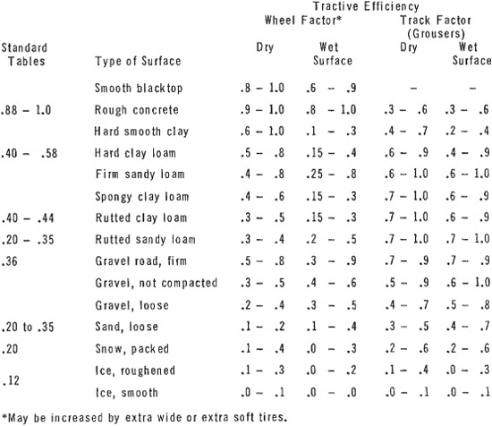
FIGURE 3.6 Tractive efficiency of surfaces.
While resistance to movement is in proportion to the weight of the whole machine, ability to move the machine, if power is adequate, depends on the weight on the drive units. All-wheel-drive trucks and most crawlers keep all their weight on the drivers. In other machines weight distribution is important to performance when traction is limited.
Manufacturers usually provide detailed weight specifications for haulers, showing the total weight and its distribution, both loaded and empty.
If this information is not available, the hauler should be weighed, one axle at a time, both empty and loaded. Different load distributions, to the front or rear of the body, can also be checked on scales.
A highway truck may be taken to scales. Off-the-road trucks and scrapers might have to have scales brought to them, which could prove difficult and expensive.
If there is no specific information on weight distribution and scales are not available, it may be assumed that a rear-drive dump truck carries about 50 percent of its empty weight or 70 percent of its loaded weight on the drive wheels. A front pull scraper, wagon, or rocker usually has 50 to 60 percent of its empty weight or 40 to 50 percent of its loaded weight on the drivers.
On climbs, vehicle weight shifts toward rear drives and away from front drives by about 1½ percent for each percent of grade. This factor increases the already considerable traction advantage of the rear-drive truck in slippery climbs.
Tire Treads. Tire treads are an important variable in traction. There are a number of tread designs, all of which eventually wear smooth. For most situations high lugs or cleats give best traction, but smoother surfaces are better on dry sand and ice. When tire chains are used, their effectiveness is reduced by high tread blocks.
Since a deep cleated tire gives best traction on soft loam and a smooth tire on loose sand, there are likely to be intermediate surfaces on which they are equally effective, or perhaps ineffective. Sometimes a well-worn tire will give as good or better traction than the new one ordered to replace it.
Flotation means the weight-supporting ability of a tire, crawler track, or platform on soft ground. This ability, or lack of it, is the result of a relationship between the weight, the area of contact, and the load-bearing ability of the ground.
The weight divided by the contact area in square inches (meters) gives the downward pressure in pounds per square inch (psi) [kg per square centimeter (kg/sq.cm)]. If this pressure is greater than the load-carrying ability of the ground, the machine will sink until it finds enough contact area to support it. Sinking increases rolling resistance. If it is severe, it may prevent the machine from moving under its own power.
Tire Pressure. When a tire carries enough weight that it tends to sink into the ground, its behavior depends largely on the relationship between its inflation pressure and the load-bearing ability of the ground.
Ground with a bearing strength of 50 pounds per square inch (psi or 3.5 kg/sq.m) will allow a loaded tire with 75 pounds (psi or 5.25/sq.cm) of air pressure to sink into it until the same area of the tire is in contact with the ground as there would be if the tire had 50 pounds (22.7 kg) of pressure and flexed to spread out on the surface.
It follows that if a larger tire were used, that could carry the load at 50 pounds (22.7 kg) of pressure, it would not sink in at all. It does not always work out just this way, but there is no doubt that bigger and softer tires greatly reduce problems with vehicles sinking in soft ground.
The formula for finding the area in square inches over which a tire will contact the ground is

On a truck with a gross weight of 60,000 pounds (27180 kg), of which 70 percent is on four drive wheels equipped with 14.00 × 24 tires, 20-ply, with 75 pounds (psi or 5.25 kg/sq.cm) of pressure, we would have a load on each tire of ¼ of 60,000 × .7, or 10,500 pounds (¼ of 27180 × .7, or 4757 kg). Then, by our formula,

If the tires were 16.00 × 24, 16-ply, 45 pounds (psi or 3.15 kg/sq.cm) of pressure, we would have

Since these loads are within the rated capacity of the tires, they will show only normal flexing, and any additional bearing surface needed will be obtained by sinking into the ground.
To find out whether the ground will support the load, we use the formula

If the ground has a bearing capacity of 50 pounds per square inch (3.5 kg/sq.cm),

We find that the necessary ground area to bear this load is 189 square inches (1,219 sq.cm). The harder tire has only 126 square inches (813 sq.cm) of ground contact, so it will sink until an additional 63 square inches (406 sq.cm) of its surface are in contact. On the other hand, the tire with 45 pounds of pressure (3.15 kg/sq.cm) spreads its load over 210 square inches (1,355 sq.cm), and should not sink at all.
Figure 3.7 shows the bearing capacities that may be expected of various types of soils. The figures should not be trusted very far, as there are many unknowns in this field.
Other Factors. For repeated crossings, ground should have two or more times the minimum bearing capacity needed for a static load as above, as impact shock during travel greatly increases effective weight. Once ground begins to yield, truck wheels dropping into holes may deliver blows several hundred percent greater than static weight.
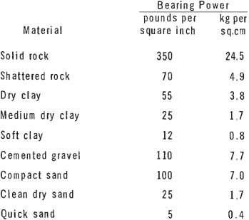
FIGURE 3.7 Load-bearing capacity.
Bearing qualities cannot be measured entirely in square inches. A country road of native soil may easily support a 200-pound (90.8 kg) person balancing on a 1-inch (2.54 cm) metal cube, but break down rapidly under 30-ton (27,000 kg) trucks having only one-third as much ground pressure per square inch.
This may be explained by the formation of a bulb of pressure that is built up underground by the sum of individual surface points or areas of pressure. Figure 3.8 shows a cross section of soil under a rubber tire roller, where each tire produces its own zone of compaction and their combined weights produce another and larger pressure bulb.
On hard ground a high-pressure tire does less flexing and has a smaller area of ground contact, and therefore less rolling resistance than a low-pressure tire. However, if the ground is soft enough for the tire to sink in at all, the low-pressure tire will develop less resistance.
The term “compaction” refers to the act of artificially increasing the density of soil. It involves the pressing of soil particles together into closer contact, and expelling air or water from spaces between them.
When the same process occurs in nature, as a result of wetting, drying, freezing, thawing, groundwater movement, and weight of higher soil layers, it is called settlement.
The density of soil is measured in terms of its volume-weight, which may be expressed as pounds of wet soil or dry soil per cubic foot, or as porosity in percent of total volume. A high porosity indicates a low density.
The purpose of compaction is to stabilize soil, particularly in built-up fills, embankments, and dams, so that it will show minimum change in volume or shape under influences of weather and time, and under the weight of structures, pavement, and traffic.
Compaction is also useful or necessary to the work of building a fill. Loose soil causes haulers to use excessive power, break drivetrain parts, and get stuck. Rain that would wet only the surface of a compacted fill might sink into a loose one far enough to create several feet of impassable mud that would stop the work.
Background. The desirability of compacting road fills has been recognized since ancient times. Early methods included driving sheep or cattle back and forth on the fill, and towing weighted wooden rollers with horses.
Reliance on natural settlement and/or simple rule-of-thumb compaction methods is becoming impractical, because of the increasing loads carried by the modern highway. There is constant pressure to revise state and federal laws to permit heavier axle and gross loads, in spite of the fact that the bearing capacity of ordinary soils has already been reached and exceeded in many areas.
Equipment. Compaction equipment is described in Chapter. 19.
Soil may be compacted by pressure, kneading, vibration, impact, or combinations. The steel wheel and sheepsfoot rollers supply pressure, pneumatic tire rollers supply pressure with some kneading, wobble-wheel rollers supply kneading and pressure, and vibratory rollers supply both pressure and vibration.
Steel wheel rollers give good results on all types of soil except clean sands, in layers from 4 to 12 inches (10.2 to 30.5 cm) deep depending on soil type and roller weight. Clay soil layers should be limited to 4 to 6 inches (10.2 to 15.2 cm), to avoid possible compaction of the top of the layer only.
Sheepsfoot rollers compact mostly with the soles of their feet, from the bottom up. As the soil is compacted, the roller rises and walks out of the ground. They do best on fine-grained soils of the plastic groups, and are least efficient in sandy and gravelly types. Excessive weight may have to be avoided, as the feet may shear soil and damage its structure.
Rubber tire rollers are suitable for use in any type of soil, but weight and tire pressure must be proper for the soil type. Results are affected by shape of tires and their air pressure and by total wheel or axle load, not by tire pressure only, as is often supposed.
Vibration is most effective in sand or gravel soils, but may increase the effectiveness of a roller in any soil. It is particularly effective at bringing excess moisture to the surface.
Trench fills and other small areas may be compacted by impact of air, hydraulic, or gasoline hammers, or vibrators. Gravel fills may be compacted by puddling—adding water until the soil is semiliquid—then allowing it to dry and settle. An immersion (concrete) vibrator will speed drying of puddled fill, by bringing its water to the surface.
Moisture Content. The most critical factor in compaction of a soil is its moisture content, since it can be most thoroughly and conveniently compacted only if it contains just the right amount of water. This quantity is called the optimum moisture content. It must be sufficient to provide a lubricant to allow soil grains to slide on each other as they are pushed together, and not enough to form an incompressible cushion between any of them.
Figure 3.9 shows the relationship between moisture content and compaction for several classes of soil.
A soil that contains too much moisture is likely to become rubbery under a roller, pushing in waves ahead of and behind it, and springing back into its original position when it has passed. This is a very common condition in highway work.
Soil that is too dry may become loose or powdery under pressure, or may be firm but not as dense as it should be. It is standard practice to add water to each such layer by means of sprinkler trucks or trailers. Extra payment may be made for watering.
Stability. If a road or runway fill is not compacted, it is likely to shrink and settle, injuring or destroying pavements and any other structures on it.
Clay soils provide poor embankment material at best, as they will usually absorb moisture in wet seasons and swell. High, but not excessive, compaction reduces this tendency. However, clay with a high content of the montmorillonite variety is very expansive when exposed to water. It will heave highway pavements and building foundations, even breaking pipes that extend through a wall raised by expansive clay.
Variable compaction may cause the greatest damage. A whole road may settle a few inches with little noticeable harm. But subsidence of a narrow strip of trench fill across a firm embankment will ruin the road surface, as will also subsidence of a poorly compacted embankment on each side of a well-compacted trench fill.
Unpaved road shoulders are more exposed to moisture than the pavement subgrade. If they absorb it, shoulder surfaces may rise noticeably above the pavement, interfering with drainage.
FIGURE 3.9 Moisture-density relationships.
Layers. Many compaction specifications stress the thickness of layers to be rolled. The best a field crew can hope to do is to come somewhere near the standard. There are some grading bosses who can keep exact control over spreading thickness and areas of a fleet of scrapers, and of the work patterns of rollers. But it is more usual for this work to be somewhat hit-or-miss. The important thing is that the layers should not be thicker than the compaction equipment on the job can handle.
Rock Fills. Layer specifications reach a point of absurdity in rock fills. Often they are subject to the same maximum thickness regulation of 6 to 12 inches (15.2 to 30.5 cm) as the soil. In practice, the thickness of rock lifts is often determined by the maximum size rock that the shovel can load.
A rock fill is usually stable if the rock is angular and is well mixed as to size. Such conditions are characteristic of both blasted and ripped rock.
Steel wheel and sheepsfoot rollers are useless on coarse, hard rock and will be damaged. Very heavy [50 tons (45400 kg) and more] rubber tire rollers and big hauling equipment provide about as much compaction as is possible or necessary.
Earth Dams. Discussion so far has been about problems of highway and similar fills. Dams do not ordinarily carry structures, but they must resist penetration by water, changes of shape, and any tendency to slump. There is more about earth dams in Chapter 6.
Fill used in dams is carefully selected for quality, with fine-grained soils used in the core and sand and gravels on the slopes. Methods of compaction are about the same as for highways, but methods and results are very carefully specified and checked.
Specifications. There are four basic ways in which compaction may be specified:
Method only
Method and result
Suggested method and result
Result only (performance specification)
Specifying the method only is usually the fairest to the contractor, who is told that a certain number of passes with a specified type and weight of roller, on layers of a particular thickness, constitute acceptable compaction. The contractor knows exactly what to do, and the equipment that will be needed.
Unfortunately, most such specifications are archaic, mentioning only steel wheel and/or sheeps-foot rollers, and giving neither the state nor the contractor the opportunity to take advantage of more recent and specialized compactors.
“Method only” relieves the contractor of responsibility for soil moisture content or other conditions beyond her or his control. If brought up to date with a wider range of usable equipment, and selection by the state of proper types for the soils in the contract area, it would provide a good contract basis.
In “method and result” the contractor is told what equipment to use and how, and also the result in density that must be obtained. If the specified equipment will not produce the desired result, there is trouble. The contractor will need a special arrangement to either change the equipment or to get by with less compactions.
The usefulness of “suggested method and result” may depend on the wording and intent of the specification. If the result must be obtained, there is no important difference from specifying result only. However, if the contractor is not held absolutely liable for the result if he or she follows the suggested method, this is a reasonable approach.
A performance specification (result only) allows the contractor to choose the method, but requires a certain density. The state will have established by laboratory tests that this density is possible, but it may develop that the density cannot be obtained in the field because of moisture or other conditions, or can be obtained only by far greater effort than was contemplated by either the state or the contractor. In many jobs it works out very well, but for reasons to be considered below it may be unfair to the contractor unless softened by irregular practices on the part of the state engineers and inspectors. It should include a provision for renegotiation.
Required density is usually specified as a percentage of maximum density produced in a particular test, such as 95 percent modified Proctor.
Laboratory Tests. Tests are required to determine the optimum moisture content of a soil, the extent to which it can be compacted, and whether it is being sufficiently compacted on the job.
The standard Proctor or AASHO (American Association of State Highway Officials) Standard Test T99 is made as follows:
A sample of soil is moistened and is then compacted in a standard mold 4 inches (10.2 cm) in diameter with a volume of  cu. ft. (0.0009 cu.m). The soil is placed in three layers of approximately equal thickness, and each layer is subjected to 25 blows of a rammer with a striking face of 2-inch (5.1 cm) diameter and a weight of 5½ pounds (2.5 kg), falling freely a distance of 12 inches (30.5 cm). This produces 12,400 foot-pounds (1,711 kg force-meters) of energy per cubic foot of soil.
The sample, which contains a known volume, is then weighed and dried at 105°C (220°F) for 20 minutes. After that, it is weighed again. The moisture content is computed by the difference between the wet and dry weights. The dry weight is recorded as well as the moisture content. The moisture content is recorded in percentage of weight by the entire dry sample.
By plotting the results of a series of these tests, using the same soil but with different moisture factors, a curve similar to that of Fig. 3.10 will be produced. This curve shows the resulting dry weights obtained in a series of tests on a single sample compacted under a uniform method with varying amounts of moisture.
There are a number of modifications of this basic test, so any reference to an AASHO modified test should specify which one. In general, they employ a heavier hammer or plunger with a longer stroke than in the basic test. The use of modifications is becoming more general because of the higher densities required in construction.
Field Tests. The standard method of testing actual density of the embankment is to remove a measured sample for laboratory comparison. A sample may be of bulk to leave a hole 8 inches (20.3 cm) wide and 10 inches (25.4 cm) deep. Measurement is made by filling the hole with a measured quantity of sand or water. The water is prevented from soaking away by lining the hole with a rubber balloon.
The Proctor needle penetrometer measures the resistance of soil to penetration by a heavy needle, by means of a spring and gauge in the push handle. It is used to compare the density of the embankment with a laboratory sample. It is very useful to check on how things are going, but should be reinforced with regular volume tests. Results in gravel are likely to be misleading.
The most satisfactory and accurate, but also the most expensive, method is nuclear testing. A device using radioactive material directs a beam of gamma or neutron rays into the ground, and counts those that are reflected back into the instrument. This count is compared with a laboratory sample. The higher the count, the greater the density.
This type of instrument is nondestructive, does not interfere with grading operations, does not depend on individual judgment, permits a large number of tests in a short time, and can be used for stony or frozen ground. On the other hand, the instruments are now both expensive and fragile.
A piezometer is a pipe gauge that is placed in the fill as it is built. It will indicate any movement of soil or soil water that would be likely to threaten to damage the embankment.
Too Much Moisture. The material taken from road cuts often contains too much moisture to meet compaction specifications in the fills.
In dry summer weather, layers of fill may be stirred up with a disc harrow, moved from side to side by graders, or sprayed into the air by a rotary tiller with the hood up. When moisture is sufficiently reduced, the surface is leveled off and the layer is compacted. If it rains during this operation, the result will be mud.
If some fill is wet and some is dry, the two types may be built up in alternating layers, that may or may not be mixed together.
In a wet season, surface drying is impractical, and no dry fill may be found in any of the cuts. Under such conditions it may not be possible to meet density specifications.
This is a very serious problem that is almost completely overlooked in the literature on compaction. It is generally passed off with a paragraph or two on correction by substituting other material or by kiln drying.
Kiln drying of such quantities would involve setting up huge and expensive plants, drastic changes in digging and hauling methods, and lengthening of hauls. It is questionable whether such operations could be included in a highway budget, or even whether improved pavement life would justify the cost.
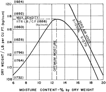
FIGURE 3.10 Moisture-density curve.
The most critical point for the contractor is that in many states the terms of the contract require her or him to produce a certain density that can be achieved only at or near optimal moisture content. If the contractor cannot get the soil down to this content, it is unlikely that the density can be obtained. See Fig. 3.10.
Theoretically the contractor should get no pay for the embankment work, and would probably go bankrupt. Actually, this does not seem to occur. Field workers in public works departments are more realistic than the design engineers, and are inclined to pass the work as long as sincere and intelligent efforts have been made to reach the specification. However, this puts both sides in the wrong if their actions become the subject of an official investigation.
Before proceeding with the details of various types of excavation, it is in order to consider some of the general problems. Mud is one of the most important of these.
Water Content. Mud is soil saturated with water to such an extent that it loses its structure and takes on some of the properties of a liquid. Even the driest soils contain some water in very thin films, and moderate additional amounts may give added firmness by acting as a binder. But when the quantity of contained water is sufficient to build up water films around the grains thick enough to serve as a lubricant so that they can move freely on each other, the soil becomes mud.
Particle Size. The quantity of water necessary to turn mineral soils into mud varies with the size, shape, and arrangement of the particles. Small grains have much less volume in proportion to the thickness of the water film they hold than large ones have, and therefore they form more fluid muds. Sharp angular grains have projections which penetrate the film and interlock, and large grains and pebbles develop high enough contact pressures to cut through the film. If there are enough fine particles in a mixed soil to prevent the coarse ones from touching, the mud will have the qualities of the fines.
A fine-textured soil such as clay will also remain saturated much longer than a coarse one, as the spaces between the grains are so small that water moves through them very slowly.
Humus. Humus, or peat, which is decayed organic material, absorbs water somewhat as a sponge does, in large quantities, and holds it stubbornly against evaporation and drainage. When saturated, nearly pure humus, as found in some swamps and peat beds, resembles a jelly, fibrous or smooth in texture, and black or brown. It is the most slippery and most treacherous of the muds. It dries very slowly, with shrinkage of 50 percent or more, to a light, fluffy soil. When mixed with inorganic soils, as in topsoil and mucks, it greatly reduces their load-bearing qualities and makes them muddier under wet conditions.
Making Mud. When undisturbed, inorganic soil is usually quite closely packed, with its grains fitted together closely, and often lightly cemented by mineral deposits. When it is dug up or pushed around, the grains are shaken away from each other into a loose structure. In this condition it can quickly absorb a large quantity of water and become a very soft mud. As it dries, the grains settle together so that less water is absorbed with each subsequent wetting. If it is compacted by rolling, tamping, or vibration before being soaked, it may become even more water-resistant than in its original state.
When a firm, dry soil is covered with water, it gradually absorbs some of it and expands in volume, but it never becomes as soft as if disturbed before wetting.
If a firm, fine-grained soil has a film of rainwater on its surface, and is passed over by a vehicle tire, the water will be forced between the surface particles and the resulting mud will be wiped off and pushed aside, leaving a new surface exposed to the next raindrops and wheel passage. Repetitions of this result in a slippery road, ruts, and mudholes.
Frost. When soil freezes, the expansion of ice crystals between the particles pushes them out of place. When the soil thaws, it is likely to become a slippery, structureless mud, often resembling toothpaste in consistency. It ordinarily firms up fairly quickly, particularly if vibrated by a heavy rain, but may persist for several months when upward seepage of water prevents settlement. In its extreme condition it will not support loads, and is made more dangerous by its occurrence in places that normally are firm, and under sod which bridges and hides it. Such places can be detected by sounding with a crowbar, and should be avoided or treated with the same precautions as soft swamps.
In northern winters, frost may stabilize a swamp so that it can be worked easily. Ice and frozen earth are liable to be variable in thickness and treacherous because of snow cover and the heat of decay of organic material. But any traveled route will gain in stability as long as freezing continues.
Freezing provides a pavementlike support for machinery, and may stabilize unfrozen mud as well. Ice lenses at the frost line absorb capillary moisture from below. If upward flow is restricted by coarse soil or an impervious formation, the mud will be dried and made firmer.
Mud from thawing is apt to render dirt road surfaces slippery, particularly on sunny slopes. Early mornings such roads are often frozen hard, and work must be done, then, in cloudy weather or at night. Tire chains are useful but may not be adequate.
Geotextile Barrier. The problem of permanent reinforcement of soft ground for embankments and foundations is now being solved by the manufacturers of sheets of geotextile fabrics. Geotextiles are permeable woven or nonwoven synthetic fabrics—polyolefin, polyester, or fiberglass fibers—as recognized by the Industrial Fabrics Association. They weigh around 5 to 25 ounces per square yard (0.02 to 0.11 kg/sq.cm), can drain water and stabilize, separate, and reinforce soils.
Geotextiles have been used to cover a peat bog, to stabilize city streets and roads in new subdivisions, and to cover many bigger areas. The geotextile fabric is made with many sheets seamed together to cover the soft ground of a harbor area with sand fill laid on top, to build up to the desired elevation for heavy industrial equipment to operate. The soft soil consolidates within 6 to 24 months so that the fill can be brought to final design height for permanent use. The runway extensions for Washington’s National Airport were made most economically by using geotextile fabrics on the muddy subsoils of the Potomac River.
The Mirafi 140 fabric performs three functions in soil stabilization: separation, filtration, and reinforcement.
In building a road across a swamp, the strip is first cleared of all hard or sharp objects or bumps. Roots, sod, and sometimes soft brush are left undisturbed.
The fabric is unrolled on the surface, with overlapping at any joints. Aggregate, usually bank gravel, is truck-dumped and spread, preferably by light equipment.
There should be a foot or more of aggregate between the fabric and truck tires, to protect it. Any excess can be shaved off after compaction, which preferably is done with a light vibratory roller.
Sand. Clean sand is as troublesome as mud to two-wheel-drive vehicles. It can be stabilized with pneumatic tire rollers and plenty of water, but the surface will loosen up as soon as it dries. Tires spin and dig down into it rapidly, with a jerking motion that is very damaging to the drive mechanism. All-wheel-drive vehicles ordinarily have less difficulty with it, but it consumes considerable power. The general problem is one of getting traction without digging in, but there is no danger of simply sinking, as in mud. Partially deflating the tires may help; smooth tires will do better than those with tread, as they will not dig down as readily. Mats of brush, wire, grass, or a thin layer of dirt may suffice to give traction.
Tracked vehicles can travel on sand without difficulty, but if equipped with grousers, care must be taken about pulling heavy loads that may cause tracks to spin, as they will then hang up quickly. The silica which makes up most sand is very wearing to the track parts, particularly when particles are angular.
Quicksand. Quicksand usually is fine sand or silt through which water is moving upward with enough pressure to prevent the grains from settling into firm contact with each other. It provides practically no support for machinery unless its weight is distributed over a large area by platforms.
Work Delays. Mud is an impediment to work in many ways. Deep mud causes equipment to bog down and to become useless until pulled out, and a film of mud may render firm footing dangerously slippery. Mud sticks to shovel buckets and truck bodies instead of dumping, and builds up in chains and tracks until they jam. It holds objects lying on it by powerful suction so that they become difficult or impossible to lift. When frozen, it can lock together and immobilize the most powerful machines. And it is much heavier than the same amount of dry soil.
Mud trouble can be reduced by using proper equipment. In general, crawlers are preferable to wheels; tracks should be the longest and widest obtainable, tires should be big, soft, and cleated; and units should be the smallest that will do the work. All-wheel-drive is desirable for trucks. Articulated dump trucks with six drive wheels work well in muddy soils.
The ability of a machine to stay on top of soft ground is affected by its ground pressure, which is usually measured in terms of pounds (kilograms) of weight on each square inch (square centimeter) of ground contact; shear, which is the load on the edge of the track or tire; and total weight.
Ground pressure is the most important factor in loose soils such as sand or dust. Shear is most important when a soft soil is protected by a harder crust or sod. It is increased when the machine is tipped, and when it pushes a load. Total weight affects deep mud, which may creep or flow from under the machine.
Grousers, cleats, and tire chains cut and churn up their footing but are necessary to get a grip on slippery surfaces.
Some wheel tractors can be fitted with temporary metal and rubber tracks which enable them to work in fairly soft places.
Special vehicles, such as the military weasel and the swamp buggies used for exploration by oil crews, are very useful in supplying fuel and other essentials to machinery working in swamps.
Wheeled Equipment. Wheeled equipment is best kept out of swamps unless they are frozen, dried out artificially or by drought, or have roads built into them, perhaps with geotextile fabric. The use of geotextile sheeting is shown in Fig. 3.11, where a roadway with moderate rutting of the subgrade when dry would become impassable when it rains. The minimum road is a strip in which the soft spots are stuffed with brush or bridged with planks. If poles are used, they should be closely fastened so that they cannot work apart and let wheels down between. Whenever possible, surface poles should be at right angles to the direction of travel.
Pole Tracks. Poles may also be used as tracks to be straddled by dual wheels. They should be straight, free of stubs or sharp projections which might cut tires, and large enough that they cannot pass between the tires toward the hub and small enough that they will not slip sideways out of the groove between the tires. The poles should be overlapped at their ends so that the wheels will not be left without support while passing from one to another.
Front wheels may be placed on skids or runners and chained down. If the mud is not very deep, they may be left to make their own way.
This procedure is for short emergency moves only.
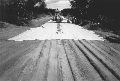
FIGURE 3.11 Road subgrade covered by geotextile. (Courtesy of Hoechst Celanese Corporation.)
FIGURE 3.12 Corduroy road cross sections.
Corduroy. A corduroy road can be built to support heavy machinery on very soft ground. It consists of logs or half logs laid across the traveled way, touching each other. They may be laid directly on the ground, on one or more stringers running lengthwise, or on both stringers and longer cross logs, called sleepers. Several constructions are shown in Fig. 3.12.
A minimum width of 12 feet (3.7 m) is recommended for one-way traffic, although it might be possible to get by with 10 feet (3.05 m). Curves should be 2 to 4 feet (0.61 to 1.22 m) wider. Cross logs may be extended beyond the road edge for additional stability.
Logs 6 to 10 inches (15.2 to 25.4 cm) in diameter are generally strong enough for the work, without being excessively heavy. Thinner ones may be used as stringers. Heavier sizes may be split for cross logs, or partly buried for stringers.
The upper surface of cross logs should be smoothed by removal of stubs and bumps, and perhaps by planing down with adze, axe, or ripsaw.
Guard logs are desirable to prevent vehicles from sliding off, to reinforce the road structure, and to retain any surfacing which may be added. Picket stakes may be placed to hold guards in position, and to bind cross logs to the outer stringers. Edges may be bound together by heavy wire, cable, spikes, or lag bolts. Such fastenings are important when the road surface is well above the ground, where the mud will not act to hold it in place.
Drainage ditches may be dug on one or both sides to remove standing water. These should be kept from 3 to 10 feet (0.91 to 3.05 m) away so that mud will not flow into them from under the logs. In very thin mud their use is inadvisable.
When a drainage channel or small stream must be crossed, the stringers can be increased in number and strength and set on sleepers on each side of the channel so as to serve as a log bridge. If clearance is doubtful, metal pipe may be used to carry the water under the stringers.
Corduroy roads are quick and fairly easy to construct if logs are on the site and usually are very strong. However, their surfaces are extremely rough, and it is advisable to cover them with gravel or other surfacing if they are to have much use. This saves damage to both machinery and road.
A corduroy road made of oak, cypress, or other strong and rot-resistant wood may have a very long life. Some softwoods, such as poplar, will rot out in 2 to 3 years. If mixed species must be used, the inferior ones will give their best service as stringers or sleepers.
Saplings or brush may be wired into tight bundles and used instead of logs for light corduroy.
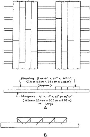
Plank Roads. Plank road constructions are shown in Fig. 3.13. These are usually more expensive than corduroy, but are easier to lay and provide a smoother surface. Rain or mud may make them very slippery so that sanding will be required.
Nails should be driven diagonally from the sides of the tread planks, as in (B), to prevent them from working up and puncturing tires. Even with this precaution, frequent inspections for nails and splinters should be made. If the wood is hard, nails should be soaped or greased before driving. Splitting may be reduced by making thin pilot holes with an electric drill.
Surface Protection. A wet soil with good load-bearing qualities, which might be readily churned into mud, may be protected by a few inches of gravel, spread before traffic uses it. Two feet of broken rock with a skin of gravel may carry heavy traffic for a while over almost any mud. Brush mats or pole corduroy under the rock gives added stability. Between these extremes is every type of condition and cure.
Fill for mud coverage should be as dry as possible and possess good packing qualities. It should be put on in sufficient thickness that the truck tires will not reach through to mix it with the mud. It is strengthened by compacting with a roller, jeep, or empty truck before carrying loaded trucks. A layer of fine-textured, hard-packing soil topped with gravel is often satisfactory, but clean broken rock in coarse sizes up to one-half the fill thickness is longest-lasting.
Flat stones should be placed on edge, whenever possible, so that they will not shift under load. Natural drainage must not be blocked. Iron or steel culvert pipe is most satisfactory on soft bottoms, as it will keep its position and resist separation and breakage.
Swamp Surfaces. Most swamps are covered with vegetation that gives them some surface stability. Wet swamp sod, in which a person’s feet will sink slightly, ordinarily will support a light crawler machine moving steadily across it in a straight line or gradual curves. Crossing should be tried with caution, particularly if the unit has narrow tracks, or high grousers which tend to cut the sod. Sharp turns, if necessary, should be made in the firmest or best-matted sections, or extra support should be provided. Bushes and close-growing saplings which can be walked down by the machine, without cutting, provide excellent natural support.
Although a shovel can be safely walked on quite soft ground, it cannot stand or work on it. If standing, its weight slowly displaces mud beneath it, and as that creeps away, the sod or crust left without support shears and breaks. This process is greatly accelerated by working, as the vibration, the variable load, and the twisting reaction to the swing all cause the machine to settle, particularly at the end where the loads are picked up.
Platforms, also known as pontoons or mats, are wood supports for machinery working on soft ground. They are most often used under draglines or other revolving shovels.
Their primary function is to spread the weight of the machine over a wide area. They also provide a relatively clean, dry place from which to work, and will act as temporary bridges over ditches and holes.
Construction is not standardized. They are generally made by the contractor who uses them according to local methods.
In general, mats for ½-yard (0.38 cu.m) shovels are 12 to 14 feet (3.7 to 4.3 m) wide, and for ¾-yard (0.57.cu.m), 14 to 18 feet (4.3 to 5.5 m). The length should be about half the overall length of the crawlers, except that they should be shorter if necessary to fit into the truck body that will have to carry them. If they are made for two sizes of shovel, they must be strong enough for the large one, and short enough so as not to be too heavy for the smaller machine.
Oak is quite generally used because of its strength and resistance to decay, and elm because of its toughness. These hardwoods have the disadvantage that they cannot be nailed readily, so it is necessary to drill and bolt. Spruce, although soft, is tough and resists splitting, can be nailed, and is lighter than the hardwoods.
Green lumber can be used. It is tougher and heavier than after curing.
Figure 3.14A shows a sample of very light construction. The loops shown at each end may be of any size cable from ⅜ inch (9.8 mm) up, fastened with two clamps. A chain is hooked to both of these and to the shovel bucket when the mats are moved. Three-eighths-inch (9.8 mm) chain is satisfactory for ordinary service with light shovels.
FIGURE 3.14A Butt joint platform.
It is a good plan to make up a special chain about 2 feet (0.62 m) longer than the platforms are wide. Round hooks should be used on the ends, preferably the lock-on type. The center should have a ring and a special hook large enough to hook on the bucket, or on the drag chain links next to the bucket.
A mat may be lifted and dragged by one side loop, but this is not as convenient as using two.
The siderails, above the deck, prevent the shovel from sliding off the side. They get in the way occasionally but on the whole are well worth having.
When nails are used, they should be long enough to hammer through the wood. The projecting point should be hammered over flat.
Bolts should have washers on both ends. Heads should be countersunk into the deck.
The laminated platform in Fig. 3.14B is suitable for any but the roughest service and will support light trucks. It is heavier to handle.
The heavy-duty type in Fig. 3.14C will take any abuse a ½-yard (0.38 cu.m) shovel can give it, for a while. It is suitable for use on rough or frozen ground, and among stumps and boulders, but it is too heavy to be convenient for ordinary soft ground.
Handling. Platforms usually are trucked as near to the job as possible, then dragged or carried by a loader or the shovel.
To walk a shovel across an open swamp on platforms, pick up two or more of them and lay them on the mud, as shown in Fig. 3.15(A). Move the shovel to the front of these, then pick up the remaining platforms and lay them ahead of the shovel as in (B). The minimum number to be used is three—two to stand on and one to move. Four are safer and easier to use, and the maximum is the number the shovel can reach when they are laid in a line behind it. Most draglines use three or four on small jobs, and four to six on large ones.
FIGURE 3.14B Laminated platform.
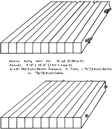
FIGURE 3.14C Timber platform, heavy-duty.
The shovel then walks to the front of the platforms, (C), and picks up those behind it, starting at the rearmost, and lays them in a line in front of itself. In (D), the platforms are laid in a curve to avoid a rock. (E) to (G) shows patterns for laying them in sharp curves. These should be avoided where possible, as the turning of the shovel has a destructive grinding action, and overlapping the platforms causes severe strains, particularly if they are equipped with siderails.
Shovel Rigs. Techniques of working from platforms vary with the type of shovel attachment being used. The most efficient swamp worker is the dragline. Its long reach enables it to keep well away from the hole it is digging, and to pile spoil far enough away to reduce slumping back into the pit or against the shovel. The sliding action of the bucket during digging and hoisting reduces trouble with suction.
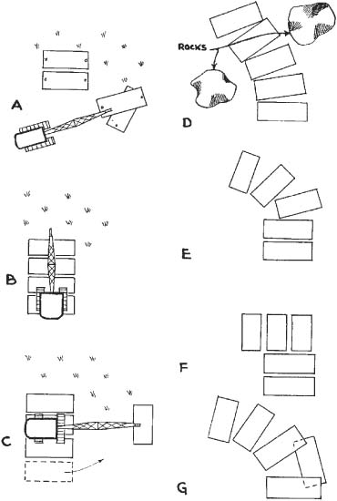
A dragline or a backhoe stands at the back of its line of platforms and digs at the rear or sides. When its work from one position is finished, it walks ahead one or more platform widths, then picks up the platforms behind it and swings and places them in the front; repeating this process as often as a move is required.
Hydraulic full-revolving backhoes are competitive with draglines. They can dig much harder material and to greater depths, and have more precise control in both digging and dumping. They are much better able to get themselves out of trouble, and to work without platforms. But their reach is much shorter in proportion to weight and bucket size. In swamp work, long reach is highly desirable, and weight increases problems, cost, and risks.
The tractor-mounted hoe cannot work on platforms unless another machine places them. Digging reach and dumping reach are poor. But if the tractor also carries a front-end loader, with skillful operation it can work in (and get out of) very soft areas without supports.
A clamshell has almost as much reach as a dragline, and can work without dragging debris, such as roots, stumps, and boulders, up against the platforms and itself. However, it has the severe handicap of pulling the bucket straight up, which in sticky mud requires overcoming suction more resistant than the weight of the bucket and load. Digging is best done off the rear or sides of the platforms, but the ground ahead can be graded before placing the platforms.
The spaces between platforms will vary with the nature of the footing. For very soft conditions, they should be placed in contact with chains fastening them together, or even laid in two layers, as in Fig. 3.16(A).
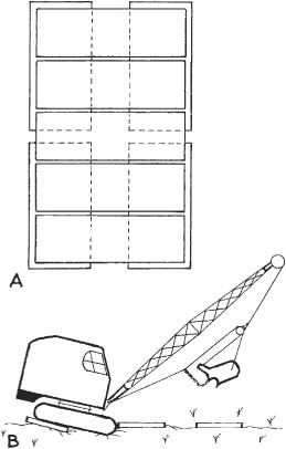
FIGURE 3.16 Overlapping and spacing platforms.
FIGURE 3.17 Blocks and side rails.
For ordinarily soft or suspicious ground, the widest spacing allowed should be that which will enable the shovel to reach the next platform before its center of gravity reaches the edge of the one it is on, so that the shovel will not tip forward, as in (B), so much that the track will push the next platform instead of climbing on it.
Blocking. Normally, a shovel can be worked on platforms without blocking. There is always a risk, however, that a dragline, or particularly a pull shovel, i.e., backhoe, will unexpectedly hook into something solid and drag itself off the platform before the operator realizes what has happened. If the platforms are slippery with mud or ice, this danger is greatly increased, and the machine is also likely to slide sideways in reaction to swinging.
On a solid platform, wood wedges chained to the platform, as shown in Fig. 3.17(A), are effective. For side protection, plank rails, permanently bolted to the side edges, or held there with pins, as shown in (B), usually are adequate.
Chaining to Platforms. For extreme conditions, the shovel may be chained to the platforms. There are many ways to do this, of which one sample is shown in Fig. 3.18. The platforms have a cable loop at each corner, by some of which the two platforms are chained together. To the outer corners of the truck frames are welded brackets holding rings or hooks. Chains are fastened to these and to the corresponding outer corner loops of the platforms, and are drawn up taut with chain tighteners in the rear. The tightness is important, as the momentum of a sliding shovel will break chains or tear out loops which would hold against a direct pull.
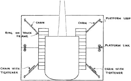
FIGURE 3.18 Chaining to platform.
All accessories, such as blocks, rails, chains, and tighteners that are to be used in mud, should be kept painted some brilliant color (not green). They are very easily lost and dug under, particularly if some emergency interrupts the routine of their use, and the bright color will greatly increase chances of salvage.
Platforms can be used efficiently only in places where the shovel has room to swing. If trees prevent swinging, they must be cut, or other methods used to support the shovel.
Suction. Lifting platforms or other objects from mud is greatly impeded by atmospheric pressure (14.7 pounds per square inch) (1.03 kg per sq.cm), which is felt as suction.
A platform 4½ × 12 feet (1.37 × 3.66 m) carries an atmospheric pressure of over 50 tons (45,400 kg). When air can flow under it freely, the pressure is upward as well as downward, and is not felt in lifting it. If air is sealed from the bottom by mud, then the lift of the shovel merely serves to reduce the weight of atmosphere and platform on the mud beneath, causing mud at the edges which carries the full atmospheric load to squeeze in under it. A thin mud will flow quickly, a thick tenacious one may stretch but not flow and keep the air locked away from the bottom.
If the suction is too strong to break by a direct lift on the whole platform, the pull should be concentrated on one side or one corner. If the mud seal is broken at one spot, it should shear off from the whole under-surface. The platform might also be lifted and dragged at the same time. Suction presents comparatively little resistance to sliding, and this motion greatly increases the shearing effect on the mud seal. Unfortunately, a dragline is apt to make a pile of mud and debris which would prevent the platform from sliding forward, and the lattice boom is apt to twist or collapse if subjected to heavy side-strain.
A method of releasing is to catch the forward edge with the bucket teeth and hoist while pulling back enough to keep hooked.
Root Mats. Trees growing closely in swamps usually form a mat of interlocked roots that will support crawler equipment, but will give it a rough trip. Openings may occur where the roots are lacking, which may be crossed by means of green saplings laid across the path of the machine, as indicated in Fig. 3.19. If it is necessary to remove trees to give the shovel space to get through, they should be cut as close to the ground as possible, as the shovel might sink while going over the stump and get hung up on it. Logs laid on each side of the stumps across the line of travel are protection against this.
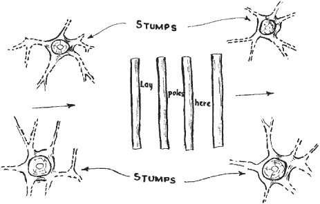
FIGURE 3.19 Support by roots and poles.
In a swamp studded with stumps, or rock, platforms break up very readily. The spaced plank type, which is generally preferred because of light weight and reduced suction, will break if used across a stump or heavy buttress root, and the heavier types will strain and splinter. Some operators prefer to pull the stumps before walking over the spot, thus exchanging the platform-breaking obstacles for a wet and uncertain footing.
It is dangerous to move a machine onto platforms which are placed with one side on firm ground and the other side in loose mud. The mud side may sink enough to cause the shovel to slide to that end and tip over. The soft side may be braced with platforms or logs, or the firm side can be ripped up, before placing the platforms.
Poles. A shovel may be walked and worked on fairly soft footing by the use of saplings instead of platforms. These should be of firm wood, preferably green, 2 to 10 inches (5 to 25 cm) in diameter, and long enough to project 2 or more feet (0.61 or more meters) beyond the tracks on each side.
An extra precaution is to place outrigger poles under their ends, parallel to and outside of the machine’s path. When the shovel has passed over the poles, they may be retrieved and used again, but the mortality rate usually is high, particularly among softwoods.
When the shovel is working, it will often be found that a pole or two under the front, or where the lifting of the load is done, will suffice to support it. With worse conditions, more cross poles and outrigger poles should be used.
If long poles are not available, short ones may be used, centered under each track, but they are not nearly as satisfactory. There is a danger that they might tip under the shovel and jam into the machinery.
In any extensive wet digging, draining or surface pumping is liable to leave a sheet of at least a few inches (cm) of water on the bottom. This is a convenience in establishing a flat bottom grade, but unless special precautions are taken, large quantities of water will be dug out along with the soil.
FIGURE 3.20 Compartment digging.
This water may run directly back into the hole, in which case the time and fuel used in lifting it are wasted. If it mixes with soil, either in the bucket or in the pile, it will tend to liquefy so that the spoil will not stand in the high, steep-sided piles which afford maximum dragline production.
Compartments. Shallow bottom water may be largely kept out of the bucket by compartment digging, as illustrated in Fig. 3.20. A ridge of clayey soil is left between the digging and the water until bottom grade is reached. The ridge is then dug out and water allowed to flow in. Some mud will be washed onto the digging surface by inflowing water and by the removal of the ridge. Compartments may be large or small.
This method gives waterfree digging for the bulk of the excavation, and can be used, with diminishing efficiency, in increasing depths of water, but not when the whole digging area is under water, as in deepening an undrained pond.
If little surface water is present but groundwater drains into the excavation rapidly enough to be a nuisance, digging can be in two or more compartments. First, the whole area is dug in layers until it gets sloppy, after which the digging is concentrated in one spot until most of the water flows into the hole made. An adjoining area, separated by a ridge, is then dug deeper and the ridge cut.
The water will now flow into the deeper hole, leaving the first one nearly dry and ready to be deepened in its turn. This alternation of digging spots can be continued to the bottom of the cut. If the area is too large to be dug in this manner, the water can be concentrated in gouges dug behind the regular layer cut.
Spoil. If enough dry or stiff dirt can be dug to build a dike along the excavation edge of the proposed spoil pile, as in Fig. 3.21, it will prevent mud behind it from flowing into the hole. There is usually ample space behind the pile so that the mud which moves in that direction makes a place for more in the pile, and increases the amount of digging that can be done from one stand. The effectiveness of the dike will of course depend on the quantity and type of dirt available for it.
If the dirt is being loaded in trucks, an effort should be made to get dry material on the bottom to reduce trouble with the load sticking in the body. Most excavating in swamps and mud is done by revolving excavators with dragline attachments.
Bulldozers. Bulldozers are not suited to wet excavation since they cannot work efficiently on artificial supports. However, they can skim shallow layers of mud off hardpan and dig cautiously in muds compact enough to give them some traction. In skimming work, it is usually best to start at one side of the mud area and make a pass removing the mud cleanly. Each successive pass should be to full depth and cut just enough into the side of the muck to fill the blade, without allowing it to slop off the other side of the blade into the cleared area. The mud should be pushed far back, as the dozer cannot climb up on it to make high piles, and there is danger of its flowing back into the hole.
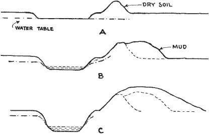
FIGURE 3.21 Dike method of piling mud.
Wide-gauge dozers are preferred, as they usually have wider track shoes for greater flotation, their weight is spread over a larger area, and they turn more readily on poor footing.
Cleats. Smooth or semigrouser tracks are unsatisfactory, as they have little traction on wet slippery surfaces. In general, tracks with new and high grousers are better than those which are worn and rounded. However, such grousers on loose soil will dig in very rapidly, and many muds will pack in between them to make a new smooth surface even with their edges so that they become ineffective.
The best solution for straight mud work where rocks or very hard subsoils are not involved is to use flat shoes, with high grousers bolted on every fourth to sixth one. This should put two cleats on each track under the machine at all times, and will give a good grip which will not clog.
A similar effect can be obtained by building up some of the cleats on a set of standard track shoes, or replacing some shoes of a worn set with new ones.
A machine with cleats of variable lengths is likely to be almost incapable of working or traveling on hard ground.
Dragline Road Cut. A permanent road should not be built over unstable mud unless absolutely necessary. Such muds, particularly if rich in organic matter, will gradually be compressed and displaced by the weight of the road, allowing it to sink unevenly. The mud should therefore be removed down to firm bottom and replaced with clean fill if possible. If it is too deep, or otherwise too difficult to move, measures must be taken to stabilize it, such as with geotextile fabric.
Shallow mud may be removed by a dragline working just ahead of the fill, and piling it to the side. The rate at which the mud pushes back into the hole determines how far ahead the dragline can be operated. A foot or two (0.3 or 0.6 m) of mud liquefied by the mixing action of the dragline bucket is usually pushed out by the weight of the fill, but sliding in of the banks must be avoided.
Surface water should be diverted and sufficient pumps used to keep the hole fairly dry. This enables the dragline operator to see to clean out the mud thoroughly without unnecessary digging of firm soil, and will prevent the fill from being turned to mud as it slides down the front of the slope. If the fill is too wide for the dragline to clear, it may be built out in sections.
If the mud is too deep for available draglines to handle, or if it slumps into the excavation before fill can be placed, or if there is not adequate equipment to keep the water out, blasting may be resorted to. Refer to Chapter 9 for more details about blasting.
Mud is easily blasted out of a limited area and spreads in a thin film over the landscape, leaving no heaps to dispose of. If a nitroglycerin or other sensitive dynamite is used, the concussion from one explosion may detonate other charges of dynamite in the mud nearby, without the necessity of using additional caps. The process, called propagation, greatly simplifies mud blasting.
Dewatering. One method offers stability equal to that obtained in normal, dry fills, but at high cost. The right of way can be dried up by draining, or well point or sump pumping, as described under Ditching and Drainage, then excavated to firm bottom with machinery. Fill may then be built up to road grade in thin, thoroughly compacted layers and with properly sloped sides. When it is complete, pumping may be discontinued and the muck allowed to settle back against the slopes.
Removal of muck in any way is expensive work, except in the rare cases where it can be sold locally for humus. The expense increases very rapidly with depth, and a point will be reached where it is good practice to stabilize the mud rather than remove it. This is particularly true if the area involved is wide or conditions do not permit side casting or blasting.
Grouting. One method to stabilize ground, as well as to provide seepage control and some rehabilitation of the ground, is by injecting a water-cement mixture which fills the voids and spaces previously occupied by water. The mixture may include some special chemicals that react favorably with the soil to form a hardened mass. Additives may include polymers to stiffen the ground. Many of the grouting techniques were developed in Europe and have slowly been copied in North America.
One technique used in ground made soft by excess groundwater is jet grouting, which originated in Europe but was brought to the United States in the 1980s. Jet grouting has been used not only as a groundwater barrier but also for excavation support, as a bottom-sealing technique to prevent pollutants from entering excavation, to combat scour beneath bridges, to stabilize slopes behind retaining walls, and frequently to underpin existing commercial and industrial foundations.
The jet grouting method involves injecting a water and/or cement grout through jetting pipes under extremely high pressures (generally 4,000 to 6,000 psi [282 to 422 kg/sq.cm]), forming a tight mix of grout and native soil. This method can strengthen soft soils or form load-bearing foundations. For example, when the historic structures in the Boston National Historical Park in Charlestown, Massachusetts, were settling, more than 8 inches (20 cm) in some places, due to decades of uncontrolled water infiltration into the loose artificial fill materials, jet grouting was used. A single-fluid jet grouting procedure was used to fill the voids under the buildings and to improve the fill quality. The single-fluid method was used because ground movement during construction is negligible and potential damage to the foundation is minimal.
Sand Drains. Muck can be stabilized if enough water can be squeezed out of it to convert it from a semiliquid to a solid. The weight of a heavy road fill has a squeezing effect, but the mud and water flow together and very little compaction is obtained for a long time.
Vertical sand drains may be used to dry up the mud so that it will support a load. They consist of columns of sand extending from hard bottom to the top of the mud, and connected at the top to each other, and to an outlet by a sheet of sand or gravel, or other drainage systems. They are discussed in Chapter 5.
Quicklime. Where the topsoil is so soft that it is impassable by personnel with boots, lime can be spread on the surface and worked in with farm implements such as a disc harrow pulled by a crawler tractor. The quicklime is obtained by cooking limestone at high temperature so it becomes calcium oxide (CaO) which reacts with water, giving off heat and expanding into hydrated lime or calcium hydroxide [Ca(OH)2]. Therefore, the quicklime added to the soil sucks up the water, changing the soil from a moldable, soupy mass to a crumbly solid. This makes the ground surface more passable.
Chemicals. If digging is done in a water-bearing sand or gravel, very soft conditions and extensive caving of banks may be experienced. This difficulty may be avoided by drying the area with well points, or by other methods described in Chapter 5, but it may be more economical to prevent water from moving through the soil. This may be done by means of cement grout, discussed above or by other chemical treatment. The grouting material displaces water, and then hardens or gels into a mass that prevents more water from getting between the soil particles.
One chemical treatment involves pumping a solution of silicate of soda into the ground through drill holes, then pumping in a solution of calcium chloride that causes the silicate to form a dense, hard mass.
American Cyanamid’s chemical grout is a thin water solution of two acrylic chemicals and one catalyst, that is mixed with another catalyst solution just before injection into the ground. A chemical reaction causes the mixture to form a permanent, water-impermeable gel, at a time that is controllable between 3 seconds and several hours. These characteristics are particularly useful in sewer rehabilitation work.
Freezing. Any soil in which pipes may be sunk can be stabilized by freezing, but the presence of salt, or certain other chemicals, may make it difficult.
It is accomplished by sinking a number of metal pipes, rather closely spaced, in the area to be stabilized. Tubing containing a refrigerant, usually ammonia, is placed in these pipes and connected to heavy-duty refrigerating apparatus. The soil water will freeze most rapidly if it is stagnant, but even a steady flow can be checked.
This is an expensive job, mostly confined to a very fine-grained mud, or deep work which does not respond to well points.
Compaction. In fresh fills, the most serious mud difficulties are due to improper compaction. Here it is sufficient to say that excellent compaction may be obtained if a fill is made in layers 6 to 18 inches (1.52 to 45.7 cm) in depth, and each layer is thoroughly rolled or tamped in all parts. If rollers are not available, trucks may be used, first empty and then loaded. Such a fill usually will be incapable of absorbing enough water to turn to deep mud. The extra expense and nuisance of making a fill in this manner, when specifications do not call for it, may be regarded as an insurance premium against the loss of having to stop a job for days or weeks because of a soft dump.
Clay. Clay fills are liable to become soft and slippery during rain. The wet surface may be bulldozed off and replaced with dry material, or the dry material may be dumped over the mud in sufficient quantity to carry traffic over it, and may be removed later. If rain is anticipated, the original fill may be left low, to leave room to cover it.
If fill is coming from two or more sources, it is sometimes possible to keep the clay in lower parts of the fill and the better material on the top.
Area Dumping. If trucked soil is too wet to be stabilized and will not support trucks after being spread, and if the ground (or lower layer of the fill) is passable to trucks, area dumping may be resorted to. A calculation is made of the amount of fill needed in a given area and the amount of each incoming load. Allowance must be made for shrinkage of the soil upon drying and after compaction, and the number of loads required in such an area may be found by dividing the cubic yards (cubic meters) required by the corrected yardage (cubic meters) of a truckload.
The trucks may then dump their loads in piles which can be left to dry, then be spread and compacted.
Buried Mud. If it is impossible to truck in the area to be filled, the mud must be covered as it is dumped with a layer of dry fill, gravel, or rock sufficient to support the trucks. Some times the mud will support a bulldozer which can roughly grade the soft fill. The dry surfacing is advanced close behind the face of the mud fill, trucks dump the mud at its edge, and the dozer pushes it over the face, digging down sufficiently to allow placement of more surfacing. See Fig. 3.22.
In such mud work, it is advisable to have at least two dozers, so that the one working in mud can be promptly rescued if stuck. Under extreme conditions two dozers may be attached to each other, back to back, by a chain or cable. As one of them pushes mud toward the face, the other backs up toward it, keeping the line slack. When the pusher backs up, the other one pulls it to firm footing. The helper Cat need not have a dozer, and preferably should be larger than the one doing the work. Wide tracks are a big asset in mud.
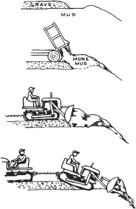
The next problem to consider is how to rescue machinery that has sunk so far into mud that it cannot move under its own power. The easiest and most attractive method is to stretch a chain or cable to some power source and pull it out. Often there is no such power available; but if there is, it should be used with caution. If the stuck machine has not sunk but has simply lost traction on a slippery surface, power can usually be applied without damage. However if it is sunk in badly, use of moderate power may be useless, and too much power may pull it apart.
Dump trucks are probably the most frequently stuck type of equipment. If one is loaded, it may be possible and desirable to dump the load, after which the truck may pull out under its own power. But if the truck is tipped sideways, as with one pair of rear wheels bogged down, the other resting on the surface, the raising of the load preparatory to dumping increases the sideward strain, and may overturn the truck (as shown in Fig. 3.23) or tear the body off its base. A winch cable attached to the front top of the body on the high side, and pulling uphill, may permit dumping of a tipped truck, but even with skillful operation, the strain on the body is considerable. Unloading by hand, or partial unloading by power shovel, hoe, or front loader may be necessary.
A shovel is a highly effective rescuer of bogged trucks. A front bucket may be placed under the rear of the frame (or, with some risk of damage, under the rear of the body) and may lift and push at the same time. A front loader can do the same, but might walk into the same mudhole; and its wider bucket may be blocked by tires. A dozer has the same problems.
A hydraulic hoe can get most of the load out of the body, then push and lift with the back of its bucket.
Digging Out. If the truck cannot be emptied, or is empty and is still stuck, and no powerful equipment is at hand, the next procedure is to dig out the wheels in the direction toward which it is hoped to move. Two-wheel-drive trucks have best traction going forward, and in many situations, such as sinking in a soft shoulder, an attempt to back out will cause the front wheels to get in worse difficulties. Any digging helps, but the best procedure is to go to the bottom of all tires, make a ramp up to the surface with a length of 3 feet (0.9 m) or more to every foot (meter) of depth, and put a board or boards on this slope, with the lower end against or under the tire. If boards are not available, matted brush, stones, gravel, or anything but mud may be used. If the axles or frame is resting on the ground, an attempt should be made to free them, but this is not often possible. See Fig. 3.24.
Even if this digging does not enable the truck to get itself out, it makes it much easier for a light machine to pull it, and it greatly reduces the danger of damage if pulled by a large machine.
Breakage. Applying brute force to pulling a deeply bogged truck may result in getting it out minus its rear axle assembly and wheels, a partial victory that brings little satisfaction. In most trucks the rear axle is attached to the frame only by the spring shackles and propeller shaft.
Lesser and more common damages are tearing off of bumpers and bending of front axles. Many trucks have no satisfactory pull points on the front end. The bumper should be used only at the fastening to the frame. If it is necessary to use the axle, the line should be attached as close to a spring as possible, and care should be used to prevent it from catching any part of the steering when tightened, or when the wheels are turned.

FIGURE 3.23 Dumping on a side slope.
FIGURE 3.24 Digging out of a mudhole.
Pull Line. The most generally effective device for extricating bogged machinery is a winch. It may be mounted on and powered by a tractor or a truck, or may be a portable winch. A power winch may have 200 feet (61 m) or more of cable which enables it to reach a long way from firm ground, or on shorter pulls, to multiply its power many times by means of pulleys and anchors. The procedure for rigging and operating the winch is the same as that described under stump pulling in Chapter 1. The use of multiple lines is often advisable, even when the machine may be debogged by direct pull, as the slower speed is less liable to cause damage. Hand winches are slow and laborious to wind in, but are powerful and can be used in places inaccessible to larger machines.
Where possible, it is best to pull the truck straight out with the truck wheels driving. If it is necessary to pull at an angle, the truck should be steered toward the pull.
A cable or chain may be stretched from the stuck truck to another truck or a tractor, with or without pulleys, and a traction pull used. Care should be exercised not to use too short a line and get the assisting machine stuck also. See Fig. 3.25.
Push. A dozer or front-loader tractor can get behind it to lift and shove at the same time, but someone should be stationed to put poles in front of it as it moves so that it will not get stuck in the hole the truck leaves.
Body Hoist. A dump body usually extends a short distance behind its hinge, so that when the body is raised, the rear edge of it goes down a few inches (centimeters). Advantage may be taken of this feature by chaining the axle tightly to the frame, perhaps lifting it first by chaining it to the front of the body and hoisting; placing a plank on the ground under the rear of the body, and fitting a stout log between plank and body. If the body can be raised, the rear edge will push down against the log to lift the frame, and through the chain, the axle and wheels. Axle or wheels can then be blocked up, the body lowered, and the log shimmed up to meet the body at its new height, and the process repeated until the wheels are high enough that a support or ramp can be put under them. See Fig. 3.26.

FIGURE 3.26 Jacking out with body hoist.
Jacking. If a heavy jack is available, the axle may be chained to the frame, the jack placed on a plank or other support, and frame and wheels raised and blocked in the same manner as when the body lift is used. If it is not possible to chain the axle to the frame, first raise the frame with jack or body hoist, then jack the wheels up with a light jack based on a board and placed under the wheel rim or hub.
Wheel Tractors. A wheel tractor in mud presents similar problems, except there is no load to be removed and it takes more digging to get to the bottom of its big rear tires.
A tractor may have a differential lock, which can be engaged to prevent one wheel from spinning independently of the other. This should be engaged at the first suspicion of bogging down.
Letting some air out of drive tires may be helpful, but if overdone may cause the tire to slip on the rim, tearing out the valve.
If the stuck tractor has a loader, the bucket may be used to push it out of trouble, preferably backward. The procedure is similar to that described for crawler tractors later.
If the tractor carries a hoe, it can lift the rear wheels clear of the ground by forcing the bucket down. It can then push it forward, or swing it to the side.
A tractor equipped with both a front loader and a backhoe can, with skillful operation, work in extremely soft ground.
If a truck or wheel tractor is stuck more because of slippery surface than sinking, tire chains, short chains threaded through wheel openings, or rope or rags tied around the tires will help to give traction.
Wheeled vehicles do best in mud or sand with large tires, or standard tires with reduced pressure. Truck tires break down rapidly if underinflated, but tractor tires usually have thin flexible sidewalls and operate at such low speeds that they can run soft for considerable periods before being damaged. However, they may slip on the rim and tear out their valve stem if too soft.
Churning. A very important item in the sticking of vehicles is to know when to stop struggling. Often a minor tow job is changed into a major project by a driver continuing to spin wheels and buck back and forth until the vehicle has sunk completely. In rescue work, the strongest measures available should be applied early, as every attempt that fails is likely to make the job more difficult, and danger of damage to the sunk vehicle more severe.
Crawler machines do not bog down as readily as wheeled ones, but can do an even more thorough job of it.
A crawler tractor may sink in mud too soft to support it, or it may dig itself in while pulling a load, or both. If the tracks are allowed to spin, the grousers act as buckets on a ditcher, digging soil from underneath and piling it behind. On soft ground they can work down rapidly this way, until the frame parts of the tractor are resting on the ground, or on a stump or other object its normal clearance would have taken it over. When the weight of the tractor rests thus on the frame, the tracks churn helplessly in air or loose mud.
Pulling Out. If outside power is available, the machine may be pulled out by a line attached to its drawbar, front pull hook, or other hold. It should be pulled straight forward or backward, if possible, with its own power being used also. The drawbar, or a dozer blade, can take almost any pull, but use of a front pull hook may pull the engine out of some models.
Poling Out. If no outside power is available, and the stuck tractor has no dozer, winch, or other helpful equipment, the first thing to try is digging a shallow ditch in front of (or behind) the tracks, a foot (0.3 m) or two wider than the tractor. In this put a green sapling, or strong board as long as the ditch, pressing or wedging it tightly against the tracks, which should then be turned slowly so as to pull the stick or board underneath. When it is well under, press in another stick, and perhaps more. Their effect will be to lift the tractor and restore the weight to the tracks, provide a wide base for support and traction, and cut off or uproot obstacles under the tractor. They are almost certain to get the machine out if it will pull them under.
If the tractor has flat shoes or grousers that will not grip the size of pole available, and no bolton cleats can be obtained, or if there is an aversion to digging ditches; planks or heavy angle irons may be drilled and bolted to track shoes on both sides. The effect is then positive, but it is necessary to unbolt and remove them as they come up at the other end. Poles or logs may be fastened to the shoes by loops of cable and used in the same manner. Short sticks should not be used unless absolutely necessary, as they do not afford nearly as much lift or traction as long ones, and they are liable to turn underneath and jam things. See Fig. 3.27.
These stratagems are equally effective at moving the tractor forward or backward, but reverse gear often has less power than low, and backward movement under difficult conditions is a severe strain on the tracks.
Cable Ramps. Another system is to fasten a cable to each track, or the two ends of a single cable to the tracks, perhaps by passing it from the outside through a hole in the shoe, and catching it inside with a loop and clamps. These cables should be stretched parallel or nearly so, straight ahead of the machine, to anchors of some sort. When the tracks are turned to move forward, they will advance on top of the cables, which will prevent them from spinning and provide a tightrope ramp on which they can climb. This technique should be used with caution in reverse, as the strain on the track may break it. See Fig. 3.28.
Chains may be bolted to the track and used instead of cables, but they are much heavier for the same strength and are seldom long enough for the job.
The tractor may also be jacked up on planks, in the same manner as a truck, and the hole filled in or bridged.
Winching Out. If the tractor is equipped with a towing winch, the cable may be fastened to an anchor behind it, and the machine will come out of the mud as the cable winds in. This should be done with caution if the presence of a stump or large stone underneath is suspected, as it might force a track off, or do some other damage. Risk can be reduced by putting blocks behind the tracks so that it will move up as well as back, or by anchoring the cable at a height, as in a large tree.
If the tractor is too badly bogged down to turn, the only available anchor is not directly in line, and the winch is of a type that the cable runs off the spool on an angle pull, then run the cable out until it is slack, then hold it with a crowbar or stick so that it reels on the side of the spool opposite to the direction of the anchor. When the pull begins, it will be off center and will have a tendency to turn the tractor in line with the anchor. If it does not do this, it will wind onto the drum in a spiral making one or more loops before reaching the edge on the anchor side, moving the tractor a short distance. The line can then be slacked and the procedure repeated.
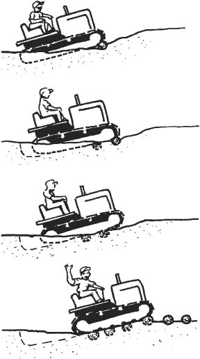
FIGURE 3.27 Walking out on cross poles.
If the angle between tractor direction and anchor is too great, a second anchor must be used and a chain from that adjusted to hold the cable in line. Use of a snatch or pulley block, as shown in Fig. 3.29, will prevent damage to the cable from the chain hook. If alignment is satisfactory but the winch does not have enough power to debog the machine, a pulley may be chained to the anchor and the winch line passed around that and back to the tractor drawbar. This will nearly double the pull.
Dozer Down Pressure. If the tractor is equipped with a hydraulic bulldozer, but no winch, the blade should be raised; planks, poles or other floats placed, dug or driven under it; and down pressure applied to the blade. If the hydraulic system is in good condition, this will raise the front of the tracks clear of the mud. Poles may then be forced under the tracks, or the holes filled with rocks, and the tractor can walk out after raising the blade. If the dozer will not raise the tractor, and there is enough oil in the system, try letting the machine cool off, as a worn pump will develop better pressure on thick, cold oil. If it still will not work, or if there is no time to wait, proceed as suggested for a plain tractor.
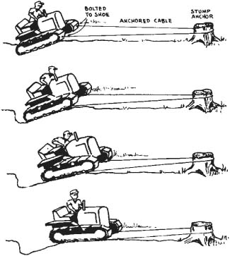
FIGURE 3.28 Climbing a cable ramp.
Cable Dozer. If a tractor equipped with a cable bulldozer is stuck, and plenty of pulleys and extra cable are available, the blade might be supported by a chain, and the control drum rigged to pull it out. The heavy pull of multiple lines should be through the drawbar or blade.
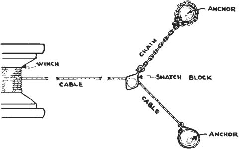
FIGURE 3.29 Changing angle of pull.
Front-End Loader. Front-end loaders equipped with flat or semigrouser shoes get stuck easily in wet holes. The bucket can be used to push it out, preferably backward. Place it on the ground in fully dumped position, apply down pressure, then rotate the floor forward to a flat position, usually turning the tracks slowly backward at the same time. See Fig. 3.30.
Poles may be placed under the bucket and behind the tracks, for extra bearing in very soft ground.
A forward pull may be obtained by placing the bucket flat on the ground, applying enough down pressure to raise the front slightly, and then dumping it slowly. It is not as effective as in reverse.
The bucket can also be used for short-distance self-moving of a machine that cannot travel because of clutch or transmission failure.
The front of the tracks can be raised off the ground by using down pressure with the bucket floor vertical, and supported by poles or blocks. The rear can be raised by shoring up the front and piling the bucket with heavy material.
Hanging Up. Tractors are frequently hung up on stumps or rocks in the absence of any mud at all, usually through digging in the tracks while moving a heavy load. The first warning is liable to be a failure of the tractor to keep its direction or to steer. The tractor should be stopped immediately and the situation checked over. If the stump (or rock) is under the crankcase guard or other smooth surface, the tractor may escape by backing or turning, or by climbing a rock or a stick placed under one track. If the obstacle has wedged into a hole or raised section, then large rocks or logs under the tracks, or even jacking, may be required to get free.
A crawler tractor may also be hung up by walking over a large flat stone or short log which flips up and catches in the chassis or between the tracks. This situation deserves careful examination before working, as applying too much power in the wrong direction may break a track or do other damage. Movement in the right direction, particularly turning one track only, may free it; or climbing up on blocks or using another power source to pull the rock out the same way it went in may work. Sterner measures are removing the track, or turning the machine on its side in order to break up the stone, or to chop the log.
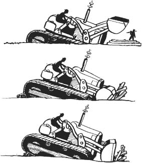
FIGURE 3.30 Pulling dozer shovel out with bucket.
Overturning. If a crawler tractor is lying on its side, it may be rolled back on its tracks by pull on a line fastened to the highest substantial structure near the center of the up side. If there is no spot above the center of gravity which will take the pull, the line should be run across the up side and what is usually the top of the tractor until a hold is found. Logs or other blocks under the line should be used to protect the tractor parts against crushing. An improvement on this is to use a pulley in a tree, or in a heavy tripod, so that the line will lift as well as pull.
If the machine is upside down, two pulls may be necessary, one to get it on its side, the other to right it. This is easiest downhill, but blocks must be arranged to prevent it from rolling farther than planned. Power should be applied slowly, to avoid bending or crushing of parts.
If no power is available, hand jacks should be obtained together with planks and blocks. A jack placed on a plank should be used to raise some portion of the tractor, blocks placed to hold it at that height, the jack released, blocks placed under the jack, and the process repeated. One jack will do it, but two are easier. It is good procedure to start jacking the part of the machine which will move the longest distance in resuming upright position, and work the jacks in as space opens up. If the tractor is dozer-equipped, the dozer frame and blade will safely take the strain of jacking. The dozer may sometimes be moved advantageously, using the starter for power.
The type of jack shown in Fig. 3.31 is particularly useful in machine salvage.
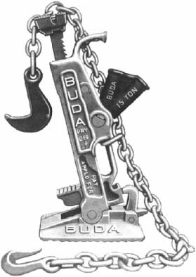
FIGURE 3.31 Equipment salvage jack.
Planks. Power shovel tracks usually have flat shoes, so that it is difficult to get them to grip poles or planks and drag them under, without excessive trenching, or bolting or cabling them on. Before work ing a dragline or other shovel in risky places, it is a good plan to get a plank 2 inches (5 cm) × 12 inches (30 cm), 3 inches (7.6 cm) × 12 inches (30 cm) or heavier, or 2 feet (0.61 m) longer than the shovel is wide, and drill holes in it to match the holes in the track shoes so that it may be readily bolted, and carry it for use when necessary as described under tractor rescue. Strain on plank and shovel will be reduced by trenching deeply to the underslope of the idler if possible. If the shovel can climb up on this plank, saplings or other helps can be placed in front of it to assist it to firm footing.
Hoisting Bucket. If a dragline is down on one end, logs or planks can be forced or dug under the high end, and the low end raised by hooking the bucket or hoist cable to a stump or other anchor, as in Fig. 3.32(A) and (B). Pulling in the hoist cable, or raising the boom, should tip the shovel forward, lifting the rear sufficiently to allow shoring up with logs.
If the anchor is close, a low boom gives best leverage. If it is distant, a high boom is better. However, a boom angle of over 45° may be dangerous, because if the hoist line breaks or comes off the anchor, the reaction might throw the boom back on the cab.
The same procedure can be used if one track is bogged and the other one is free.
If the shovel is down all around, trenches can be dug to permit bracing under one end. This is used as a pivot to raise the other end, which is then shored up. The boom is swung to an anchor on the opposite side, and the hoisting and blocking repeated.
Two anchors may be chained together for greater strength, or to secure a better direction of pull.
If no anchors are located in the proper direction, and it is not practical to make one, the bucket can be used as counterweight. The dump cable is shortened to permit holding a load far out. A bucketful of the heaviest dirt available is dug, the boom lowered so that the bucket can be held just above the ground. Rocks or weights are piled on the bucket until the shovel tips. If the rear of the tracks is not high enough, it can be brought up by raising the boom.
In any blocking work a loose track is a nuisance, as it will hang down and impede placing of supports. The slack can be readily taken out by placing a jack on the track frame and raising the upper section.
Drum Line. A shovel can sometimes pull itself out of trouble by a line attached to one of its own drums, or to a drag bucket. These lines are too fast for a smooth, steady pull, and the drums are so high that there is a tendency to pull the front of the shovel down. Better results will therefore be obtained if the line is passed through a pulley chained to the anchor, and back to the bottom of the dead axle. If several pulleys are available, and all additional lines run to the dead axle, a very powerful, well-directed pull will be obtained.
Jamming Chains. A special precaution to be observed with shovels is to keep the drive chains free from material of any kind. Stretching or jamming these with mud, gravel, or debris not only is a severe strain on the chain, but also by increasing friction within the chain and with the sprockets absorbs a large part of the drive power needed at the tracks.
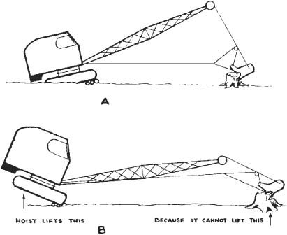
FIGURE 3.32 Raising by an anchored bucket.
Straddling. It is risky to work a shovel that is straddling a stump or boulder, unless the ground is known to be entirely firm. The rhythm of load, swing, and rebound causes the tracks to work their way down into soft earth, particularly at the load end. If there is a thin layer of sod or hard soil overlying unstable material, the top will give an appearance of solidity, but if it breaks through, will let the machine sink rapidly. Ordinarily, slight sinking can be ignored or checked by poles under the tracks, but if it causes the shovel underparts to rest on a stump, it is a more ticklish situation.
The underparts of a shovel, between the dead axles, are more vulnerable to damage than any part under a tractor. In mud there is often nothing to do but to get out in any way possible and hope for the best; but if possible, any projection reaching up into this vulnerable area should be carefully watched during rescue work.
The power shovel may be freed from an obstruction by anchoring the bucket and hoisting, or by walking it up on logs, or by using a plank bolted to the tracks, or even by using a long crosscut saw to cut off a stump while still under it.
Counterbalancing. If a shovel sinks so far on one side that it is in danger of overturning, the boom should be swung to the high side and lowered as much as practicable, the bucket extended, and weighted or anchored, then raised to serve as a counterbalance. This should prevent further tipping and may make it possible to shore it up.
Overturning. If a shovel is overturned or so steeply tipped that it cannot be operated, the swing lock should be set, a line should be attached to the top of the A-frame and to any available anchor on the high side, and drawn taut to prevent further settling. If this line can be attached to a power source of sufficient strength, the shovel may be pulled upright, but this should be done slowly, with careful attention to any tendency toward bending the A-frame or other parts.
If no adequate power is available, a platform must be laid or constructed on the ground, and the shovel raised with jacks and blocks. The best and cheapest blocks are old railroad ties, but any sort of beams or heavy planking may be used. The actual raising of a shovel is so intricate, so dependent on the position and construction of the machine, and so liable to result in severe damage if done improperly that it cannot profitably be described here. The best method is to hire people who specialize in rigging and machine moving, work with them, and remember their methods.
If a shovel starts to tip during a swing, the bucket and load should be dropped, if possible.
Counterweight. If a shovel is heavily counterweighted to carry a long boom, and the boom is removed to install another attachment, the shovel has a tendency to turn over backward. Removing counterweight is usually too much work to be practical. The shovel may be walked slowly to its other attachment, with a high heavy sawhorse or some other support dragged or pushed along under its tail as shown in Fig. 3.33. Or a line may be rigged from its A-frame to a tractor or heavy truck moving ahead, and kept taut, a device which can be used not only to steady it but also to pull it upright if it does “sit down.” Another system is to bring the attachment to the shovel.
FIGURE 3.33 A basic shovel is tail-heavy.
Hydraulic backhoes sink in mud just as readily as other excavators, but they are much better able to get themselves out.
If any solid anchor is within reach, it can be gripped with the bucket teeth, the bucket crowded in to pull the shovel toward the anchor, and down pressure used to raise the near ends of the tracks as they move.
If there is no anchor, or ground firm enough to act as one, poles or other supports may be placed close to the tracks (or wheels). The back of the bucket is placed on them, and down pressure exerted to raise the machine high enough to put supports under it.
The bucket may also be placed against a bank, the ground, or artificial helps, and forced outward to move the shovel back.
If the carrier is a tractor or a truck, the working end of the machine can be moved sideward by forcing the bucket down to raise it, and then swinging. This may also be done with a crawler if the end opposite the bucket is not deeply buried.
A weakness of tracked vehicles is the possibility of going off the track. When this happens, it may mean that the track is in a heap alongside the machine, the track wheels are resting on the ground; but more often it means that the track rails are not engaging the wheel flanges properly, being displaced to either side, and contacting the inner surface of the track shoe. Operation in this condition soon leads to the complete separation of machine and track.
Jumping or running off the track occurs most often during sharp turns on uneven ground, and is likely to indicate that tracks are too loose or have a broken link, or track and wheel flanges are worn, or that wheels are out of line. It is usually accompanied by a snapping or grinding noise, and if suspected, the machine should be stopped immediately and inspected, as every inch of movement makes it harder to get back on the track.
If the track is off the truck rollers only, it will usually swing back into place if the track is raised off the ground, by running the bull wheel or idler onto a log or other lift, or by jacking. If the bull wheel is on hard ground, forcing down a hydraulic dozer blade will often raise the track sufficiently.
The principle involved in getting a track back on a bull wheel or idler is similar to that of installing a tight fan belt on a car. It cannot be pulled or pried enough to stretch it over the flange of the pulley; but if it is held in one end of its place in the pulley, and the pulley turned, the wedging action will stretch the belt over the flange, and the part of the belt already in the groove will draw the rest of it in.
Similarly, with the track it is a problem of getting part of the track in line with the flange, and turning the wheel to draw it on. If the track is partially on the wheel, simply turning it in the proper direction does the job. If it is off the flange completely, it may have to be pried into line with a crowbar, jack, or chain, and the track adjustment will usually have to be loosened as well.
If the track is off the upper part of the bull wheel, but still engaged with even one tooth at the bottom, and with the truck rollers, the machine should be moved forward slowly. The sprocket teeth will mesh properly with track appearing from beneath the rear truck roller, and will carry the wrongly meshed section overhead into the slack upper section, where it will be straightened out by the support roller. If the upper part of the bull wheel is correctly engaged, and the lower section off, the track will work into place if the machine is reversed. However, it might be necessary to pry with a crowbar to prevent the track from jumping off the rear roller.
If the track is entirely off the bull wheel flange, but still meshed with the truck rollers, the machine should be moved forward. The bull wheel will roll onto track held correctly by the truck rollers, and, perhaps with the aid of vigorous prying, should mesh with it and pass this correct meshing up around itself. If the track is also off one or more truck rollers, the tractor should be backed so that the bull teeth can mesh with track held correctly by the support rollers. This may require more prying, or a pull in the correct side direction from another power source, or if the disabled machine is a shovel, from a line to its boom.
Should the track be off at the idler, the above methods are still good, with directions of travel reversed. If the track is tight, it may be loosened to facilitate crossing the wheel flanges. If the track is off the support roller, it usually can be replaced by lifting with a crowbar.
If the track is off the bull wheel, truck rollers, and idler but is still on the support rollers, the whole track and wheel assembly should be raised off the ground, and the bull wheel rotated backward. The track can be engaged with this at the top by use of a crowbar, and will be pulled into engagement with the rest of the bull wheel, then the truck rollers and finally the idler. Caution should be used to prevent the track from coming off completely in one place while being meshed in another.
If none of these stratagems work, or if the track is entirely off the wheels, the track adjustment should be loosened and the track “broken” by removing a lock and driving out one of the hinge pins, using the bull wheel as a brace. On most makes, there is only one master pin which can be used. The side of the machine should be raised off the ground, the track placed correctly under the wheels, the machine lowered, and the track wrapped around the bull wheel and idler. The ends should be pulled or forced together at the bull wheel or between it and the top of the idler, by chain tighteners, block and fall, winch, jacks, elbow grease, or any other means available, and the pin inserted and locked. This is a difficult and laborious job, even on a small machine, except for experienced personnel; and on a large one it may require the use of other machinery to handle the track.
It is sometimes easier to replace a track, after opening it, by walking the machine off it onto a plank or beam, aligning the track behind it, and walking it back, than to shift the track around under the machine.
This type of work has been rendered much more difficult by changes in track design and fabrication. A single master pin may be difficult to identify and to get at. When found, it may be so tight that it cannot be driven out until the links are heated with a torch, and the links may be bent by the heavy hammering, during either removal or replacement.
It is common practice among service workers to cut a pair of links with a torch; then take the whole track to a press to be reassembled. A minor incident may be turned into an expensive and time-consuming project in this way.
Split master links make this drastic step unnecessary. They permit opening a track by removing a shoe, then taking out four bolts. Opening the track and closing it are greatly simplified.