The grader, motor grader, or motor patrol, is a machine used principally in shaping and finishing, rather than in digging or transporting. It is available in sizes ranging from 35 to over 600 horsepower (26 to over 448 kw), in a variety of constructions.
Except for a few light models that are rear-mounted tractor accessories, a grader consists of a wide, controllable blade (moldboard) mounted at the center of a long-wheelbase, rubber-tire prime mover. The blade is usually held at an angle to travel direction. It will cut, fill, and sidecast. These functions can be performed separately or at the same time, in any combination.
A grader may be used as a prime mover or carrier for a number of accessories. These include snowplows and side wings, belt loaders, arm-mounted clearing tools, bank slopers, trailer drags, and disc harrows, in addition to scarifiers or rippers.
The typical grader works for more than 15 years. The average machine is rebuilt twice. The first time is for the transmission after about 8,500 hours of use, whereas the engine should not need an overhaul until 12,000 to 14,000 hours of service.
Most heavy graders are tandem drive units of the type shown in Fig. 19.1. The diesel engine, with 125 to 275 horsepower (93 to 205 kw), is mounted at the rear, and drives four single wheels in tandem pairs through gears and chains. The frame connection to the front axle is long and high, to allow space for carrying and manipulating the moldboards or blade under it.
The central location of the blade, and the long wheelbase of the machine, provide natural stability for the cutting edge. Smooth-acting, multidirectional control provides precision finishing ability.
Weight range is from 13 to 20 tons (11.8 to 18.1 metric tons). Lighter grading machines will be discussed in other sections. Grader terms are given in Fig. 19.2.
Clutch. In many types of grader operation, the engine clutch may be used frequently under heavy load. It is required to be always smooth in operation. A clutch may be retained even when the machine is equipped with torque converter.
Transmission. Graders need slow, powerful gearing for heavy or precise work, moderate speeds for lighter or less fussy jobs, and also travel speeds up to 20 to 30 miles per hour (32.2 to 48.3 kw/hr). There must also be a choice of reverse speeds, as some heavy work may be done backing up, but most reversing is for return travel only, and should be brisk. There may be six to nine forward speeds, and two to nine reverse, in either direct drive or power shift.
FIGURE 19.1 Heavy motor grader. (Reprinted courtesy of Caterpillar Inc.)
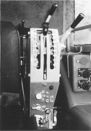
An eight-speed, direct-drive, power-shift transmission pattern is shown in Fig. 19.3.
If there is a converter, it is usually single-stage. It may be equipped with an output shaft governor, to keep ground speed uniform in spite of changes in load. There may be an input clutch in the converter, or a modulating pedal to momentarily disengage the transmission (and power to the wheels) while moving the blade. The clutch is also used for small, exact machine movements.
Hydrostatic Drive. The CMI tandem graders use an all-hydraulic drive system that replaces clutch, torque converter, transmission, and a parallel shafting. There is a fixed-displacement piston pump driven by the engine, which supplies power to a pair of motors geared to a two-speed rear axle.
Power Train. Figure 19.4 is a top rear view of the rest of a power train in a typical transmission-equipped grader. A bevel gear on the transmission output shaft is meshed with a bevel on an intermediate shaft, which turns the inner, live, or drive axles through spur gears.
An option available for some graders is variable horsepower. With that variable, when the grader is shifted to higher gears, an electrical system on the transmission moves an automatic stop to a higher setting on the fuel governor. More fuel is injected, giving more power for high-speed, light-load work. For example, Caterpillar’s 140H grader moves from a net 150 to 185 horsepower (112 to 138 kw) in gears 4 to 8 forward and 3 to 6 reverse.
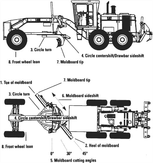
FIGURE 19.2 Motor grader terms.
The tandem drive case carries the outer axles, supports the weight of the machine, and provides protection and lubrication. It is pivoted on the inner axle housing, to permit both wheels to follow ground contour.
Tires. Tires are of a special heavy-duty design for grader work. They are preferably the same size all around, but front ones may be smaller and/or lighter, unless it is an all-wheel-drive grader. Traction tread is usual, but the fronts may be ribbed.
Size range is from 13.00-24 (33.00-61 cm), 12 PR up to 23.5 × 25 (60.00 × 63.5 cm), 12 PR.
Brakes. There are usually brakes on each of the four drive wheels, but none on the fronts. They may be either shoe or multiple-disc design, and are applied by booster-assisted hydraulic pressure. Or there may be a single disc brake in the transmission, acting through the four wheels.
The parking brake is usually on the lower transmission shaft, on the end opposite the drive pinion, and is operated by a hand lever.
FIGURE 19.3 Power shift controls. (Reprinted courtesy of Caterpillar Inc.)
Throttle. Basic governed engine speed is set by a hand throttle, which may be a lever on the console.
There is usually an accelerator for speeding the engine beyond throttle setting, and a decelerator for slowing it. These may be combined in one rocker pedal, providing acceleration for toe pressure and deceleration for heel pressure.
FIGURE 19.4 Grader power train.
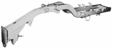
Frame and Front Axle. The rear of the frame is a pair of beams that support the engine and the power train. Forward of the operator’s station these slope upward and converge into a single beam of reinforced box cross section. This may slope down to the front axle hinge, or end in a column above it. See Fig. 19.5.
The front of the frame may be a mounting plate for front-end accessories, and/or project forward far enough to serve as a narrow bumper.
The front axle is compound. The lower section usually carries weight of the machine, may be arched high in the center for clearance over windrows, and ends below the wheel spindles. It oscillates on a central pin, and is hinged to wheel spindle brackets just below the kingpins.
The upper section, of lighter construction, is substantially a straight bar (lean bar) hinged to the tops of the hub brackets. It can be moved from side to side by a hydraulic cylinder, or by mechanical means. When moved off-center, it causes the front wheels to lean sideward. The angle may be as much as 18°. See Fig. 19.6.
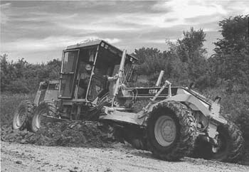
FIGURE 19.6 Leaning front wheels. (Reprinted courtesy of Caterpillar Inc.)
Wheels are leaned to increase their resistance to sliding sideward on the ground because of load on the blade, or steering stresses.
Steering may be mechanical with a booster, or by a hydraulic cylinder located behind or above the axle, and operating through a more or less conventional linkage. The cylinder control is equipped with a follower valve that keeps a direct relationship with the position of the steering wheel. Special arrangements may be made to avoid interference between leaning and steering.
Blade. The blade is the principal working part of a grader. Most of it is a curved piece of steel called a moldboard. The distinction is chiefly that “moldboard” emphasizes its function in causing dirt to roll and mix as it is moved.
Standard moldboard lengths in tandem graders are 12, 14, and 16 feet (3.7, 4.3, and 4.9 m), with some 10-footers (3-m) in small machines. Two-foot (0.61-m) extensions are sometimes added for light work or long side-reach. Height is usually 24 inches (61 cm), but may be as much as 31 inches (78.7 cm).
The cross section is such that dirt being pushed has a rotary movement, rising at the bottom and falling forward at the top. This characteristic, combined with the usual sideward drift caused by working it at an angle, makes spillage over the top very unusual.
The bottom is fitted with a removable and reversible wearing edge, with separate pieces (end bits) at the corners.
The blade is supported and held in position by a pair of heavy curved brackets, called circle knees. They are attached to the underside of a rotatable ring, called a circle. See Fig. 19.7.
Tilt (Pitch). The blade may be fastened to the knees by a hinge bar at the bottom, and a curved slide at the top. This construction permits changing the tilt (forward lean) of the moldboard.
The adjustment may be manual, with clamp nuts to be loosened and then retightened, as in Fig. 19.7, or by hydraulic cylinders controlled from the operator’s station, as in Fig. 19.8.
The blade is usually kept near the center of its tilt adjustment, but may be tipped up to 44° forward and 6° back.

FIGURE 19.7 Circle and moldboard.
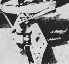
FIGURE 19.8 Moldboard with power tilt.
Blade Sideshift. Many grader operations can be made more efficient by extending the blade a greater-than-normal distance to the side. This move can usually be made with the circle controls, but they disturb the side-to-side slope. It is often better or easier to shift the blade itself, by sliding it along the knees. For extreme reach, both the circle and the blade adjustments may be used.
With power sideshift, the move is made by holding the blade clear of the ground and obstructions, and sliding it sideward by means of the control valve for its hydraulic cylinder.
Drawbar and Circle. The drawbar is a V-shaped (or sometimes T-shaped) connection between the front of the grader frame and the circle. It is rigid with the circle, and fastened to the frame by a ball and socket, or a universal fitting, that allows limited angular movement from side to side and up and down.
The drawbar carries the full horizontal load on the blade, as other connections provide only vertical and side support.
The circle is a toothed ring that is rotated in or on a supporting frame by a circle turn mechanism. Pads and shims provide for low-friction movement, and for adjustment of clearances.
The circle is turned by a spur pinion gear meshing with teeth cut all around it, usually in the inside. The pinion may be turned by a shaft driven by the engine power takeoff or by a hydraulic motor, or by a direct-mounted hydraulic motor and reducing gears. In each case, movement is controlled by a lever in the control console, at the operator’s station.
It is important that the blade angle, which is controlled by circle rotation, be capable of exact adjustment, and that it remain in place during work, without drifting or creeping.
Lift. The blade is lifted and lowered through the circle by a pair of arms or cylinders, supported by the frame and fastened to the sides of the drawbar at the rear.
Direct lift by the pair of two-way cylinders, Fig. 19.9, is superficially the simplest method. But cylinder rods are subject to change of position caused by seepage of fluid past the piston, or in the valve. Such creep can be prevented, or compensated, but corrective devices involve loss of simplicity.
Hydraulic cylinders can usually be made long enough to take care of full range of position without manual adjustments.
Circle Sideshift. The circle sideshift, or lateral shift, swings the circle and blade to the side, usually to the right.

FIGURE 19.9 Circle lift, direct hydraulic. (Courtesy of John Deere Company.)
FIGURE 19.10 High reach with blade.
When the move is mechanically powered, a curved track is mounted on the underside of the frame. A long, curved gear section slides on this, being moved by a pinion gear based on the frame. An arm is fastened by ball and socket joints to the right side of the gear section and the left side of the drawbar, for reach out to the right.
Turning the pinion for right shift moves the gear outward and upward to the right, pulling the drawbar and circle with it. For left shift, the arm is fastened to the left side of the gear and the right side of the drawbar, and the pinion rotated oppositely.
Sideshift to the right raises the blade increasingly on the right side and lowers it somewhat on the left. The lift levers must be manipulated if it is to be kept level.
A hydraulic cylinder mounted on one side of the frame, with its piston connected to the opposite side of the drawbar, can be used to shift the circle.
Blade lift cylinders may be based on a hydraulic saddle or cross piece on the grader frame. This may be designed to rotate on the frame when locks are released. When free, it can be turned by action of one lift cylinder, then locked in a side position.
The principal use of circle or lateral sideshift is to position, or start to position, the blade at a steep or vertical angle offside, for slope work. On many machines, manual adjustment of telescoping arms is required also.
A combination of circle and blade sideshifts will put the blade a long way out, as seen in Fig. 19.9, to work in spots too soft to support the grader.
Blade Vertical Position. The moldboard blade can be positioned for shaping a bank or embankment slope, as seen in Fig. 19.10. This is done by moving the circle out and at an angle with a horizontal plane as shown in that figure. The extreme angle is for the blade to be vertical or at a 90° angle from the horizon. This is possible either to the right or left side of the motor grader. The movements are done entirely by hydraulics.
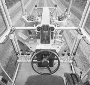
The control levers for the tools or working parts of the grader are usually arranged in a more or less straight line on a console on the dash.
There are five basic controls that are always present: the two blade lifts (right and left), circle turn, circle shift, and wheel lean. Common additional controls are for scarifier, and blade shift. A dozer or a snowplow might have another lever, or use the scarifier control. A rear ripper will have one or two levers.
Location of controls is not completely standardized. Figure 19.11 shows the control station of a Caterpillar grader, and Fig. 19.12 indicates location of the major control levers in four other machines. Individual graders may have lever locations switched to suit operator preferences. They are arranged for the operator’s convenience as shown in Fig. 19.13. New Caterpillar motor-graders have joystick controls, as described below, with one for each hand.
FIGURE 19.11 Grader operator’s controls. (Reprinted courtesy of Caterpillar Inc.)
All these shown levers are two-way, operating in forward and back positions, and holding in the center. Manufacturers have not introduced the multifunction joystick, like those in excavators and loaders, in graders, for fear of interfering with operator control.

FIGURE 19.12 Four grader control sets.
FIGURE 19.13 Operator’s convenience with controls. (Reprinted courtesy of Caterpillar Inc.)
Joysticks. Caterpillar has introduced the use of two joystick controls, one on either side of the operator, to replace the eight control levers on the earlier models of their motor graders. This allows the operator to manipulate all eight levers of previous models with fewer arm and shoulder motions. Operation of the joysticks is more or less intuitive. To turn to the right, the right hand joystick is moved in that direction, and the turn circle for the moldboard is turned by twisting that joystick. Other movements can be learned quickly by an experienced operator. The joysticks are electro-hydraulic and have an articulation return-to-center button to return to the neutral position.
Hydraulic. Many graders use all-hydraulic control for some or all of their functions. The three-position valves are similar to those used in other hydraulic equipment, but must be of the metering type to allow gradual and/or partial engagement whenever necessary for slow and precise movement.
Precautions against creep in these systems include irreversible worm gearing, and clamps that hold shafts from turning or piston rods from sliding, when valves are in neutral. They are pressure-released whenever valves are engaged to move the parts.
Scarifier. The scarifier is a set of teeth used for breaking up surfaces too hard to be readily penetrated by the blade. The teeth, consisting of rather slender shanks with replaceable tips, are set in a bar with a flattened V shape, as seen in Fig. 19.14, that is narrower than the grader; or in a wider straight bar. It is pulled by a pair of beams hinged to the bottom front of the frame, and is usually raised and lowered by a hydraulic cylinder. Angle of penetration may be adjustable from the operator’s station.
The shanks are wedged or clipped in place, and may be readily adjusted for height, or removed. A full set, often eleven in number, is used for shallow penetration and light work, and in material that crumbles into fine pieces. For deeper penetration, or slabby material, every other tooth or two out of three may be removed.
Individual teeth are not designed to take the full push of the grader, and caution must be used in hard material and among rocks to avoid bending or breaking them.
Scarifiers used to be almost standard equipment but are rather less used now. One can speed up grader work, and greatly reduce wear on the blade. It may be used in the same pass with the blading, or separate passes may be made for loosening and for shaping.
FIGURE 19.14 V-scarifier mounted under circle.
It is usually necessary to remove the shanks, or set them high in the bar, in order to reverse the blade. They may interfere with cutting flat-bottom ditches and handling high windrows.
Ripper-Scarifier. This unit, Fig. 19.15, which mounts on the back of a grader, may be fitted with 11 teeth for scarifying depths up to 9 inches (22.9 cm), or with 5 heavier ripper teeth for penetration to 14 inches (35.6 cm).
It is raised and forced down by a hydraulic cylinder. The lift frame is of the parallelogram type that keeps the teeth at the same vertical angle, whether up or down.
A rear scarifier or ripper will handle much heavier work than a standard front-mounted one, it can process a strip the full width of the machine, and it is not in the way of the blade. However, it adds to machine length so that it is awkward in close quarters, usually produces coarser and more difficult-to-grade pieces, and cannot break ground on the same trip that it is bladed.

FIGURE 19.15 Rear-mounted ripper. (Reprinted courtesy of Caterpillar Inc.)
Front Attachments. The front of many grader frames can be built out to form a narrow vertical bumper, forward of the tires. This may have limited use for protection in straight-on collisions, and for occasional pushing of other vehicles.
It may carry a dozer blade raised and lowered by the scarifier cylinder or by separate controls, which can be convenient in rough work, particularly in leveling piles.
A snowplow, preferably of the V type, is often fitted to the heavier machines, to provide possible work in the winter months. Chains should easily be put on the drive wheels for snowplowing.
Blade Stabilizer. The stabilizer is a shoe or skid plate that can be rested on or pressed against the ground behind the blade.
In high-speed, shallow work a grader blade may develop various kinds of vibration, including a long-period rhythmic bounce or lope, or a short-period chatter. These cause a wavy, rough, or washboard surface on the work, discomfort to the operator, and extra machine wear.
The stabilizer, which is under separate hydraulic control, can be put in a dragging position where it will steady the blade and dampen or eliminate vibration. It can also be used as a support shoe to limit the cutting depth of the blade.
Blade Bowl. A blade bowl consists of two sideboards, a spreader bar, and a cutting edge. It is attached at the ends of a standard moldboard, and is supported from the circle by an adjusting bolt. The edge is ordinarily a little lower than the moldboard edge.
This attachment converts the blade into a bottomless scraper bowl. The leading edge cuts and shatters material, which is held by the sides and caught and moved forward by the blade. When a depression is reached, dirt falls into it and is smoothed off by the moldboard edge.
The bowl is used only with the blade set straight across, and where somewhat more dirt must be moved than is normal to grader operation.
A majority of graders have frames that are hinged just forward of the engine, with pivoting controlled by a pair of hydraulic cylinders. This permits the front frame section, which carries the circle and blade, to be turned at an angle of 20° or more to the tandem power section, as in Fig. 19.16. In addition, normal sharp-angle steering of the front wheels is retained.

FIGURE 19.16 Tight turn with articulated grader. (Courtesy of John Deere Company.)
FIGURE 19.17 Crab steering with articulation.
With two points of turn, these machines can make a U-turn in less than two times overall length, a remarkable feat for a tandem grader. A differential may be required between the drive axles to minimize scuffing.
Independent steering of wheels and frame may provide operational advantages. As indicated in Fig. 19.17, the front end can be offset to the side by steering front and rear in the same direction (crab steering), so that its wheels will not have to tangle with the windrow or other obstruction, while the tandem rear is kept squarely behind the blade. Front wheels can still be leaned or turned as necessary to resist any remaining side-thrust.
Automatic Blade Control. Several automatic systems are available for control of hydraulically hoisted grader blades. Slope regulation is the most widely used.
With this there is a pendulum device mounted on the grader blade, that remains perfectly vertical in a right-to-left or cross plane, regardless of movements of the grader. It is coordinated with transistor computer circuits. See Fig. 19.18.

FIGURE 19.18 Sonar sensor grade control.
FIGURE 19.19 Stringline for grade control.
The operator sets a dial at the cross slope wanted, which usually is from job specifications. He or she then operates the grader, keeping the leading edge of the blade at the desired grade.
The instrument, operating on battery power and through solenoid valves, raises and lowers the heel of the blade to keep the correct slope. Corrections are made at the rate of 10 or more per second, so a high degree of accuracy can be obtained.
It is usually necessary to keep the blade at a predetermined angle with the grader’s direction to have the slope the same as that set on the dial. A sharper angle reduces the effective width, and therefore changes the amount of slope.
Some controls include a sensor on the blade circle, which corrects for changes in angle and allows more flexibility.
The next step up is to add a sensor to keep the leading edge of the blade on grade. This is carried by an arm projecting beyond the side of the machine. It may terminate in a finger (sensing fork) guided by a stringline, as in Fig. 19.19, or a small wheel rolling on pavement or on a previous pass by the grader.
The grade and the slope corrections are usually separate, with grade controlling the leading edge and slope the trailing one.
Such controls are by no means a sleeping license for operators. They have to steer, work the throttle (so far), and be sure not to run into anything. If a too-heavy cut lugs down the grader, the operator must override the control and raise the blade.
Laser. An almost-final step in automation is grade control by laser. See Fig. 19.20. It is adapted only to graders that already have slope control.
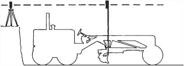
FIGURE 19.20 Laser grade control.
The background of this system is a laser, a beam of intense (usually red), highly concentrated light, that can maintain an almost pencil-thin beam for many hundreds of feet.
Lasers, and many of their uses, are described in Chap. 2.
For mobile machines, the laser shines down on a prism, which casts a basically horizontal beam. This can be adjusted to job grades, slope up or slope down. The prism revolves rapidly, casting the beam over a circular pattern.
A mast is fastened to the leading edge of the blade, and kept vertical by a pendulum and hydraulic minicylinders. It carries a set of laser-sensitive cells that activate solenoids in the lift valve to lift or lower the blade whenever necessary.
Load. Automatic grade regulation devices usually know nothing about load. Any one of them will stall a machine if a cut to grade is too heavy for it, or will try to fill a hollow without enough material in front of the blade. They are therefore limited to finishing sections that are already almost on grade, and must be closely supervised by the operator and the foreman.
General. The following discussion refers to the tandem rear-drive grader with hydraulic control, unless otherwise indicated.
The grader is normally moved forward while working. It can work in reverse by using the back of the blade for spreading or smoothing; or by reversing the blade so that its cutting edge faces to the rear.
In forward operation the grader is kept in line by steering, and by leaning the front wheels away from the direction of thrust or toward the direction of turn. The wheels may also be leaned to avoid rubbing vertical banks.
Adjustments. The blade is controlled in a number of ways. The ends can be raised or lowered independently of each other, or together. It may be positioned across the line of travel, parallel to it, or at any angle. It can be shifted to the side and into a vertical position by hydraulic power. There are also mechanical adjustments for extending its range.
The blade is ordinarily kept near the center of the tipping adjustment so that the top of the blade is directly over the edge. Increasing the lean forward decreases cutting ability and causes the blade to ride over its load rather than to push it. It diminishes the likelihood of catching on solid obstructions and may be used for rapid, light planing of rather regular surfaces and for mixing operations. When leaned back, the blade cuts readily but tends to let the load ride over its top, and to dig into obstructions. In machines not carrying a scarifier this tilt may be used to cut hard surfaces.
Bulldozing. A grader blade may be used as a bulldozer to a limited extent, often in spreading piles of loose material. If there is space to work beside the pile, the blade should be extended well to the side, and the pile reduced in a series of cuts, as shown in Fig. 19.21.
If there is not room enough to do this and the piles are not too high, the front wheels may be driven over them. The front axle will push the top off, and the blade will cut as much more as power permits.
The blade should be kept well below its highest position so that if the machine gets hung up on it and loses traction, it will be possible to raise the blade to restore weight to the wheels.
Piles to be distributed by a grader should be spread as much as possible while being dumped.
The grader can also be used for light cut-and-fill work in building and regrading roads.
The load to be pushed is limited by the power and traction of the machine and will usually be much less than by a crawler of the same weight, although it will be moved faster. The blade itself is quite low, but being more concave than the dozer blade impacts a more pronounced rolling action to the load so that a large quantity can be pushed without spilling over the top.
FIGURE 19.21 Spreading a pile.
If the blade is lowered on the right only, the other lift arm will remain stationary and the circle and blade will pivot around it, causing the left end of the blade to rise about one-quarter of the distance the right side lowers. If the left corner is to be held in position, it must be lowered intermittently while the right side is lowered steadily. This effect occurs on either side.
Keeping track of both ends of the blade is necessary and may be the hardest technique for the beginner to learn.
If the blade is raised to its full height and the controls are left engaged, the lift arms will continue to rotate inward until stopped by the frame. The blade will be lowered during the movement from top center to the frame, although the controls are in the RAISE position. If the controls are moved to DOWN, the blade will rise until the arms are past center, after which it will respond normally.
If much dozer work is to be done, it may be advisable to install a front dozer blade.
Sidecasting. When the blade is set at an angle, the load pushed ahead of it tends to drift off to one side, as in Fig. 19.22. The rolling action caused by the curve of the moldboard assists this side movement. As the blade is angled more sharply, the speed of the side-drift increases, so that the dirt is not carried forward as far and a deeper cut can be made.
The sideward movement of the load exerts a thrust against the blade in the opposite direction, which tends to swing the front of the grader toward the leading edge. This thrust is handled by leaning the front wheels to pull against the side-drift, and steering enough to compensate for any side-slipping which occurs in spite of setting the front wheels to lean.
The most usual way in which to describe blade setting is to say that a blade set straight across, as in Fig. 19.21, is at zero, and all other settings are described by their angular distance from that position. Most road shaping and maintenance are done at a 25 to 30° angle, with straighter settings for distributing windrows and sharper ones for hard cuts and ditching.
The angle of the blade is regulated by the circle reverse control. The mechanism is self-locking and can be turned any desired amount. In some makes it can be adjusted only while the blade is empty or doing light work, in others while pushing a heavy load.
Sideshifting the circle from center changes the slope of the blade, requiring compensating lift adjustments. Sideshifting the blade itself does not affect slope.
Planing. If the blade is set at an angle, it can be used to plane off irregular surfaces by lowering them sufficiently that enough material will be cut off the humps to fill the hollows. Enough extra material should be cut to keep a partial load in front of the blade. The forward and sideward movement of the loosened dirt serves to distribute it effectively. If a windrow is left at the trailing edge of the blade, it is picked up on the next pass. On the final pass a lighter cut is made, and the trailing edge of the blade is lifted enough to allow the surplus material to go under rather than around it, to avoid leaving a ridge.
This type of light planing will produce a smooth surface under favorable conditions, but the fill in the hollows is liable to settle or be compressed below the cut sections. Also the blade may chatter in a very shallow cut, particularly if the mechanism is loose or worn.
A more thorough method is shown in diagrams in Fig. 19.23. A series of cuts are made across the area to a depth sufficient to reach the bottoms of the holes, or at least to 2 inches (5 cm). The large windrow of loosened dirt is then spread back evenly over the area.
It is easier to get a smooth surface with this method because of the advantage of working loosened material and the more uniform distribution with a full blade. The surface will tend to remain smooth after settling or rolling.
It is desirable to vary the blade angle during this work, the first cuts being taken with a straighter blade than the later ones, and the first spreading pass having a sharp angle which will be reduced on each following pass as the size of the windrow is reduced.
Windrows should not be piled in front of the rear wheels, as they will interfere considerably with grading accuracy and traction.
Crowning. When the piece to be smoothed is a dirt or gravel road, it is generally crowned so that water will flow off to the sides. Figure 19.24 shows a sequence of passes in a crowning operation. Road material is bladed inward from the shoulders or ditches, and the top of the crown is cut with the blade at zero angle, or at a slight angle which will sidecast some material to either side that may require it. The windrows are then spread by putting the blade at an angle of 10 to 25° toward the center, and using a fast working speed. The blade is held above the level of the undisturbed surface so as to avoid collision with solid objects. The speed causes the loose material to be thrown from the blade, so that it will feather out and blend at the top. Any ridge built in the center is then spread out at speed with a straight blade. This should finish the job, but it may be desirable to backblade or rework some sections where proper crowning was not obtained.
FIGURE 19.23 Refinishing a flat section.
If the road is gravel or other imported material and the ditch or shoulder is loam or clay, the road may be made muddy by blading in too much from the edges. Since the road must be finished so as to drain off the sides, it may be necessary to blade off high spots on edges outward.
Sods and other debris brought up on the road from the ditches interfere with grading, as lumps catch under the blade, leave ruts, and block the sideward drift of the dirt. If labor or raking equipment is available, it is best to remove the debris from the side windrows before making the center cut. If the grader is working alone, the operator may occasionally climb down to remove a particularly annoying piece, but most of it will be left on the road to dry out and be broken up by traffic.
Stones are a more serious nuisance, both in making smooth grades difficult or impossible and in causing damage to machine and operator during cutting. If the cut is shallow or the road dirt compacts readily, it is possible to blade loose stones out of the road while grading it.
Large rocks or those firmly embedded in roads or shoulders are dangerous. If the blade hooks into one too solid to move, the grader will jump sideward or stop abruptly. This imposes severe shock on the blade, circle, and power train, and is liable to throw and injure the operator. Danger of serious consequences increases greatly with higher speeds, so that all cutting should be done in low gear and often at part-throttle where buried rocks or roots are expected.
Work Patterns. The following discussion will concern work done by single graders. However, it is often efficient to have two or more of the machines working together, each performing one step in the work sequence. This speeds the job, produces better results than working small sections with individual machines, and reduces or eliminates blocking of roads with windrows.

FIGURE 19.24 Reshaping a road.
Road building and grading may be done on three general patterns. One is to work the two sides alternately, turning at the end of the strip. Another is to do one side at a time, working in both directions by means of a reversible blade. The third is to do one side at a time, with the reverse trips nonworking or utilized for light work with the back of the blade.
The pattern used is determined by the length of the strip being worked, the turning space and footing, and the reversibility of the blade. The machine does its best work going forward, and this increased efficiency must be balanced against the time, labor, and risks involved in turning. In a long run even difficult turning conditions may take an insignificant part of the working time, where easy turns may not be justified on a short run. A general rule is that a grader should not be turned if the strip is less than 1,000 feet (305 m) long.
Turns. In turning, the front wheels are leaned all the way over in the direction the front of the frame is to turn, and are left in this position for both forward and reverse movements until the turn is completed. If ditches or rough ground must be used, the machine should be backed into or across them. The oscillating tandem drive will readily climb ditches or obstructions which would be difficult to cross with front wheels.
Turning may be a serious problem. See Fig. 19.25. When the grader lacks a differential, the rear wheels drive straight forward and the tandem arrangement gives them considerable resistance to sideward movement. Weight on the front wheels is light, and even when leaning properly, the tires may not have enough traction to turn the machine on loose material, but will skid and slide sideways.
If the front tires do grip enough for a sharp turn [minimum radius is about 25 feet (7.6 m)], the rear wheels on the inner side of the curve must spin or those on the outside drag enough to compensate for the different distances they travel. Turning a grader sharply therefore results in scuffing and gouging, which may be sufficient to damage soft surfaces.
It is therefore often necessary to make a gradual turn either by swinging in a wide circle or by jockeying backward and forward in order to avoid damaging or loosening the turn spot. It is sometimes possible to do most of the turning on ungraded areas where no damage will be done.
Other factors affecting the choice between turning and working in reverse may be idle travel distance between the end of the work and the first possible turning area, interference with traffic while turning, and chances of getting stuck.
Tandem drive affords powerful traction, but a careless operator may hang the blade or circle up on ridges or rocks, and the front wheels particularly may sink into mud with the same result. Recently filled ditches which have become water-soaked make grader traps. Repeated sharp turns on sandy soil may loosen it enough that the rear wheels will spin in it.
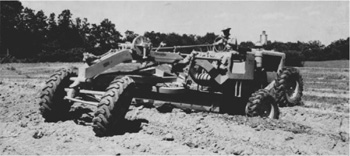
FIGURE 19.25 Turning on rough ground.
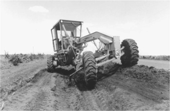
FIGURE 19.26 Excavating side ditch for roadway. (Reprinted courtesy of Caterpillar Inc.)
If the lifts are in good condition, many graders can be unstuck by putting blocks under the blade and applying down pressure. This will normally lift the front wheels off the ground so that they can be shored up, and the blade can then be lifted clear. If the pressure is applied to the rear corner of a sharply angled blade, it may lift the rear wheels on one side. The scarifier will lift the front only.
Large front tires—the same size as on the drive wheels—give better front-end flotation and are more effective in climbing ditches and banks and in holding the machine to its course on slopes, turns, and loose ground.
Road Building. A grader, without assistance from other machines or hand work, can shape up a road across a field by digging a pair of parallel ditches and using the soil to build the road crown. See Fig. 19.26. However, sod can make the finishing operation tedious and unsatisfactory, as it tends to ball up under the blade and catch and pull out of loose surfaces. For this reason, the strip should be thoroughly disked before grading is commenced.
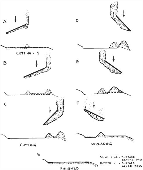
The outer ditch lines are marked by stakes or by the edge of the disked strip. The first cut on each side is made about 2 feet (0.6 m) inside the edge, Fig 19.27(A). The blade is held at a very sharp angle, perhaps 50 or 60°, with the leading edge just outside the wheel track and the windrow rolled off under the grader. The cut is a light one, made primarily to mark the edge of the work and to hold the wheels against sideslipping.
The next cut is made at about a 25° angle, as in (B), casting the spoil beyond the inner wheels. If the windrow is large enough, it is spread toward the center, as in (C). Otherwise, additional ditch cuts are made until sufficient material is piled to justify a spreading pass.
Ditch cuts, alternated with casting or spreading, are continued until the ditch is the proper depth. The outer slope is then cut, as in (D), and the spoil moved up the inner slope, as in (E) from whence it can be spread over the road.
FIGURE 19.27 Ditching for fill.
The other side is done in the same manner, and the fills are blended at the top. Ditch cuts, except the first one or two, can be made in either forward or reverse. Light casting and spreading can be done in either direction, but forward is more efficient if the windrow is heavy.
Manufacturers recommend doing forward ditch cuts and other heavy grader work in second gear, at a speed of 3 or 4 miles per hour (4.8 or 6.4 km/hr). Blading windrows and similar handling of loose soil can often be done in third gear at speeds up to 6 miles per hour (9.7 km/hr). However, when there is loose rock, lower speeds will pay off in improved quality of work. In the presence of buried obstructions heavy enough to stall the grader, very slow movement may be required for protection of both the operator and the machine.
If a wide-bottom ditch is required, the further operations shown in (F) and (G) are undertaken. Slices are cut from the inside slope of the ditch, cutting down to the level of the original bottom and leaving a ridge. This is cut out by running the grader with its outer wheels in the original bottom, and setting the blade with its leading edge even with the outer tires and at a sharp angle so that it will cut only the width of the desired flat bottom. The spoil is piled on the bottom of the inner slope, from whence it is cast onto the road and spread by following passes.
The number and sequence of passes are affected by the depth of the ditch, the width of the road, and the resistance of the soil.
Figure 19.28 indicates a series of steps that can be taken to restore a shoulder on a paved road.
All-Wheel Drive. Traction on all wheels makes it possible to push larger loads with the same weight grader, and working in mud or sand too soft for conventional drive.
In working, the front and rear axles can be offset from each other to either side, as in Fig. 19.26. This steadies the grader against sidethrust, and enables it to increase its effective sidereach by running a front wheel up on a bank, or in a soft gutter, while the rear wheels stay on more level or firm ground. It also allows sideshifting of the trailing wheels to avoid running on a windrow.

FIGURE 19.28 Reshaping a road shoulder.
The graders discussed so far have been of the high-powered, heavy-duty type, or lighter models patterned directly after the big units.
There are also lighter machines, 10 tons (9 metric tons) or less, that are simplified in structure. The most conspicuous difference is that the blades cannot rotate in a full circle. Circle sideshift may be limited or lacking. See Fig. 19.29.
They have a net 35- to 90-horsepower (26- to 67-kw) engine with standard single or tandem drive with the engine over the drive wheels. Length is less than 24 feet (7.3 m), height is 10 feet (3 m) or less, and turning radius is generally less than 20 feet (6.1 m). Their maximum speed is 20 miles per hour (32.2 kmph), or less.
The blade is generally 10 feet (3.0 m) long, and is supported by a ¾-turntable resting on the circle. It is rotated through less than a half-circle by a hydraulic motor and self-locking reduction gears.
Blade lift is by two direct-acting cylinders cradled on frame brackets. Circle sideshift is manual, with pin-and-hole adjustments of a telescoping arm. Blade sideshift may be either manual or hydraulic.
Steering and leaning front wheels are hydraulically controlled. A scarifier can be mounted behind the blade, or at the rear.
Comparison with Heavy Graders. Light graders do not provide the full range of blade positions, blade angle usually cannot be changed while working, and total weight and power not only are much less, but are even smaller in relation to blade width.
This disproportion is necessary because chassis width cannot be reduced far without loss of stability, and a moldboard should be long enough to reach past the wheel line even when sharply angled.
The result is that full-width cuts must be shallow, except in loose material, and the operator should not expect to load the blade as full or move it as fast as with the heavier machines.

FIGURE 19.29 Medium-light grader. (Courtesy of New Holland Construction.)
FIGURE 19.30 Rake blade. (Courtesy of York Modern Corp.)
These graders cannot slope banks too steep for them to walk on, dig flat-bottom ditches narrower than the tread, cut in reverse, or move heavy windrows in one pass.
On the other hand, they can work in narrow, crooked roads and driveways, around buildings, and among obstructions where the large machines would be at a disadvantage. They can often do maintenance and light construction jobs more economically.
Drawbar Grader. Light grader blades can be readily mounted on the back of wheel tractors equipped with a three-point hitch, as described in Chapter 15.
The blade can be locked straight across, at seven different angles to either side, or reversed, by pulling a lockpin and rotating it by hand. It can be given a moderate cross slope by raising or lowering one of the lower hitch arms. Draw is adjusted by shortening or lengthening the upper arm.
More elaborate models have a greater choice of working angles, built-in adjustments for slope, and means to offset the blade to obtain greater reach on one side.
As the blade is entirely behind the tractor, it lacks the stability of the under-frame mountings, tending to dig when the tractor starts to climb, and to rise when the tractor starts to tip forward. This is partly compensated for by the use of an automatic leveling device in the drawbar control valve.
Rake Blade. A light grading blade may be made up of a set of curved teeth fastened to a crossbar frame, as in Fig. 19.30. This model has alloy steel teeth 30 inches (76 cm) long, 1 inch (2.5 cm) wide, and spaced a little more than 1 inch (2.5 cm) apart.
The caster wheels are removable for doing rough work. The cross frame just behind the tractor wheels can be fitted with ripper teeth. There is a low grader blade that can be folded down across the bottoms of the teeth when rake action is not desired. A three-point hitch provides for lift and adjustments.
The principal use of the rake is to sift stones out from gravel on roads or from soil being shaped and planted. The stones are sidecast into a windrow, along with other oversize objects, while loose soil shifts between the teeth.
Stones may be sidecast off the area by a succession of passes, pulled into piles with the rake set straight across, or picked up by a loader or by hand.
Rakes are also used to spread crushed stone and blacktop; to remove trash, break up lumps, distribute soil in seedbed preparation; and to cover seed.
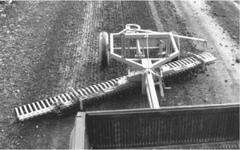
FIGURE 19.31 Towed rake scraper. (Courtesy of York Modern Corp.)
Towed graders depend on a tractor or truck for movement. The grader controls may be hydraulic, mechanical, or manual. Those with power controls may carry a small gasoline engine, or be operated by a valve and tubing from the tractor. The tractor operator may run the grader also, but it is more usual to have two operators.
Steering, or tracking, is controlled by angling the draw tongue and shifting the frame along the rear axle.
Towed graders are made in quite small sizes, and are sometimes equipped with stone rakes, smoothing drags, and other accessories. Sometimes the front axle is removed, and the gooseneck mounted directly on a hydraulic lift tractor drawbar. See Fig. 19.31. This change makes it possible to back the machine as a semitrailer—an important convenience in redoing short pieces and in repeated scraping of hard spots. The weight transfer improves wheel tractor traction.
A towed grader can also be used to advantage behind a motor grader to avoid blocking roads and to eliminate the need for return trips. When a ditch is being cleaned out toward the road, the resulting windrow may be a serious obstacle to traffic. If the patrol tows a grader behind it, offset toward the center of the road, it can spread the windrow in the same trip.
If a tractor operator works the towed grader controls also, he or she must alternate between looking ahead for steering and behind for grading. Either the quality or the speed of work usually suffers as a result, but it is still a satisfactory practice under many conditions.
There are quite different automatic leveling, spreading, and trimming machines that are used in final preparation of highway lanes for paving. These represent the most elaborate and efficient development of the grading machine. They are also readily changed over to paving machines, for either concrete or asphalt.
FIGURE 19.32 Preparing a subgrade. (Courtesy of CMI Corporation.)
Autograde. The CMI Dual Lane Autograde Trimmer-Spreader, Fig. 19.32, is the original and apparently the most successful type and will be used for description.
The basic machine consists of two augers and two strikeoff blades under a wide, short frame that is supported and propelled by four crawler track units, at the ends of horizontal legs.
The augers and blades are under both hydraulic and mechanical control from the operator’s station. Leveling of the machine by means of hydraulic jacks in the leg supports, and steering, are under both manual and automatic control.
References used for automatic control are stringlines and/or completed grades or pavements.
Mainframe. The mainframe of this model is a boxlike unit, about 28 feet (8.5 m) wide and 10 feet (3.0 m) long.
Its flat deck supports the power unit, which is made up of a diesel engine and a set of hydraulic pumps; the operator’s station with its control console or panel; and a two-section tank containing fuel and hydraulic fluid.
The augers and blades, called collectively the subframe components, are held within and beneath the deck by slide plates or bars, and are supported by hydraulic cylinders and mechanical stops.
The flooring is partly an open grating that permits the operator to watch the behavior of the units beneath. A waist-high railing surrounds the deck. An opening and climbing rungs are provided at each side. A cab is optional.
Legs. This size machine is supported by four legs, extending forward and backward to crawler drive units. Single-lane models may have three legs.
Each leg is normally attached to the mainframe by a pair of horizontal hinge pins at the bottom, and the piston rod of a hydraulic cylinder near the top. When in working position, the cylinder is retracted to clamp the leg firmly in place.
Steering. The crawlers are swiveled for steering, with front and rear sets under separate control.
The same mechanism is used front and rear. A two-way cylinder is mounted horizontally across the outside of the mainframe. The piston rod is anchored to the frame. The cylinder is fastened to a bracket-supported slide bar.
In Fig. 19.33, expanding the cylinder moves the bar to the left, retracting it moves it right. The bar is connected at both ends to link rods that move wide, rigid steering arms under the legs. The arms swivel the crawlers through yokes.
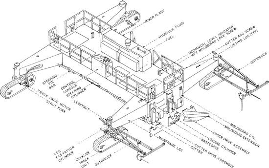
FIGURE 19.33 Automatic two-lane processor. (Courtesy of CMI Corporation.)
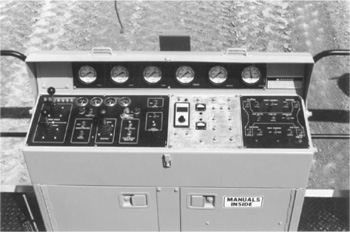
FIGURE 19.34 Control console. (Courtesy of CMI Corporation.)
Steering is usually controlled automatically by front and rear sensors and a stringline while working. During travel, and work without a line, it is operated by a pair of switches on the console. See Fig. 19.34.
Turning front and rear tracks to the same angle in opposite directions enables the machine to follow curves accurately. Turning them equally in the same direction sideshifts it without any change in centerline direction. Intermediate positions make possible very delicate maneuvers.
The work of the Autograde is done chiefly by two full-width, horizontal, 30-inch (0.76-m)-diameter augers, backed by two high, full-width blades or moldboards. These units are known collectively as subframe components.
Each of them is divided into right and left sections, with a hydraulic lift cylinder at each outer end and one in the center. Mechanical depth indicators extend from near the lift points up through the deck.
Cutter. The front auger is called a cutter. It takes care of initial digging, pulverizing, and spreading operations.
There are two 14-foot (4.3-m), 12-inch (30.5-cm)-diameter tubes. They carry one welded-on spiral of helicoid flighting, and a spiral of digging teeth. The tooth shanks are welded into the tube, and have replaceable carbide points.
Spirals are usually oppositely pitched on the two halves, so that if they are turned in the same direction, all material will be moved outward to both sides, or inward. If rotated in opposite directions, material will be shifted to one side.
The front moldboard is close behind the cutter, and holds material in contact with it until it passes under the edge or off to the sides, ensuring a constant supply for filling hollows.
Discharge to the sides is controlled by the cutter doors. These are hinged plates which are raised manually to allow free flow of material, or lowered for various degrees of restriction, and secured in position by pins.
Auger. The rear auger has only smooth helicoid flights, with no teeth. The flighting is installed in short hinged sections, wrapped and bolted on an inner cylinder.
Otherwise, general construction is similar to that of the cutter. It is split into right and left sections with separate drive, with lift cylinders at the center and sides. Drive motors and mechanisms are identical.
The flow of material out the sides is controlled by waste gates. These are similar to the cutter doors, but are hydraulically adjusted from the operator’s station.
Moldboards. The front and rear moldboards generally are similar in construction. There are separate right and left halves, with a shared lift mechanism in the center and separate lifts at the sides. They are about 43 inches (1.1 m) high, only slightly concave to the front. Wearing edges are standard grader blades, bolted in place.
Each lift includes a hydraulic cylinder, and a slide bar that moves up and down inside a square channel secured to the mainframe. This mechanism braces the moldboard against working stresses.
Each of the rear moldboard sections has a large, square opening or window near the inner end. This is normally closed by a removable section, which is kept on hangers on the back of the mold-board when the window is open.
These windows are opened when surplus material is to be left in a windrow in the center of the work strip for later removal, or is to be fed into a reclaimer, which will be described below. When windows are open, the auger sections are rotated to move material toward the center. Some adjustment of flighting sections may be advisable for maximum efficiency.
Base Reclaimer. The subgrade or base reclaimer is an accessory mounted across the rear Autograde legs. It picks up surplus material discharged through windows in the rear moldboard on a conveyor belt.
This belt discharges onto another belt that can direct the material anywhere within a 180° arc. It is high enough to load following trucks over the cab. See Fig. 19.35.
Controls are at the operator’s stations on the Autograde.
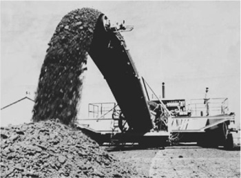
FIGURE 19.35 Base reclaimer. (Courtesy of CMI Corporation.)
Pumps. The hydraulics are powered by six pumps. There are five axial-piston hydrostatic pumps driven from the rear of the engine, and one pressure-compensated pump at the front. These, with the electrical system, use the full power of the engine, as there are no mechanical drives.
All of the hydrostatics are driven by a gearbox mounted at the rear of the engine. Each of them is a cam-regulated, reversible, variable-displacement unit operating in a closed loop with its motor or motors. However, a single 35-gallon (132-liter) reservoir, a cooler, and a three-filter system are used by all of them.
Four pumps supply fluid separately to the four motors at the outer ends of the cutter and auger sections. The fifth usually takes care of all four of the travel motors.
Track Drive. Each track has an axial piston drive motor, with fluid circulation through high-pressure lines in the leg. All motors have fixed displacement, so that torque and speed are regulated by the pressure and volume received from the pump.
The operator’s control console, Fig. 19.35, has three panels or groups. Included are what might be called rotation control levers, two for the left and right cutter sections, two for the auger, one for the tracks, and one for the engine throttle.
Except for the throttle, these levers are neutral when centered, increase speed as they move away from neutral, and change direction of drive when crossing neutral.
One square panel controls the height of the working units relative to the frame. Rubber-covered toggle switches actuate valves in solenoids that raise and lower cutter, auger, and moldboard sections, and the waste gates and any extensions.
CMI’s standard Hydra-Mation, a patented automatic control system, is a fully proportional all-hydraulic system. Information from a preset stringline, or lines, is transmitted by aluminum wands attached to direct-acting, servo-valve-proportional sensors. Individual flow control at the sensors provides for fine-tuning. The standard elevation control may be operated either manually or automatically. The standard control system includes equipment for four-point control (dual stringline), lock-to-grade, or automatic reference control of elevation.
Stringline. The general principles of setting up a stringline were discussed in Chap. 2. It is a continuous line of taut string, or occasionally wire, that is exactly parallel horizontally and vertically with an edge of a proposed grade or surface.
For satisfactory results with the Dual Lane Autograde, the string should be between 18 and 30 inches (0.46 and 0.76 m) above desired grade, and 5 inches (12.7 cm) above obstructions.
Overriding. The operator can use the toggle switches on the control panel to override the automatic action, and lift, lower, or turn the machine if desired. As soon as he or she releases a manual control, the automatic returns the machine to its preset condition.
Hydraulic Sensor System. Movements of the wand open and close ports in a very small and precise hydraulic valve. Fluid in a pressure line is blocked, or directed through either of two lines to small cylinders that operate the raise or lower (or left or right) ports in the main control valve.
Subframe Components. The four subframe tools—cutter, auger, and two blades—are lifted, lowered, and leveled as a group by the automatic leg-elevation mechanism. But they remain largely under individual manual control.
The rear moldboard is set with threaded bottom stops, so that it cannot be dropped below grade. But it can be raised to clear an obstacle or for some other reason, although then it should be immediately returned to bottom.
The other three units are not usually limited, as they have less (or no) effect on final grade, unless manipulated so as to starve the rear moldboard of material.
The cutter should be adjusted upward if tooth marks show behind the machine, or downward if the rear auger or moldboard has to grind through hard, unbroken material.
Starting a Grade. The relationship between stringline setting and the grade and centerline varies from job to job and section to section. The grade changes with each successive cutting and spreading pass in the same strip. It is therefore necessary to set the automatic controls for each work run.
First, a section large enough for the Autograde is graded to a reasonably smooth finish and approximate grade. This may be done by other equipment, or by the machine itself under manual control. Stringline(s) is (are) set or rechecked carefully.
The Autograde is then operated manually to place it in precise level and side-to-side position. The rear moldboard is set so that its bottom edge is exactly at grade, and preferably flush with the bottom of the side frame.
Threaded bottom stops are set manually from the deck to hold it from going lower.
The sensors are adjusted, one at a time, to be in a null or neutral position when in proper contact with the string. The machine is then operated for a short stretch, the grade it produced checked by instrument, and any necessary adjustments made.
The finished strip should be checked by engineers at frequent intervals during work.
Rough Ground. These machines are usually operated on finished or semifinished surfaces, where corrections to final grade are relatively small. However, the machine may also be operated on irregular or rough ground that is free of large stones and vegetation. But heavy work may interfere with accuracy, so that it must be brought back for a second or finishing pass.
If the rough work includes filling hollows, a second pass must be made after compaction.
Whenever a second trip will be needed, the first grade should be left high, so that the machine will have something to work with when it comes back.
Superelevations and Crowns. Superelevated (banked) curves have a straight but tipped cross section. This may be indicated by two stringlines. If these are properly set, the machine will automatically take care of transitions from flat cross section to banked slope and back again. The CMI cutter assemblies are fixed at the outboard ends, and will crown 7 inches (17.8 cm) up and 3 inches (7.6 cm) down. The basic cutter is equipped with 226 carbide-tipped teeth.
If the straight sections are crowned, careful operator attention is required to set the crown originally, and to make proper transitions from crown to superelevation and back to crown.
In the original setup, the outer edges of the rear moldboard are set at zero on the indicators, and the center is raised hydraulically by the amount indicated on the plans.
In making a transition to a curve, the operator must have the engineers’ instructions about the stations at which it begins and ends, and divide that part of the run into a number of small bits of lowering of the center, to make a smooth and precise adjustment.
As the curve ends, the crown is gradually restored by lifting the center.
If the operation is on one stringline with a cross-slope system, the operator must also keep track of variations in transverse slope as the roadway enters and emerges from the most steeply banked stretch.
Compaction is an absolute requirement in at least some part of most earthmoving projects, and is usually worth its cost in filling and backfilling even if it is not required. Its underlying principles were discussed in Chapter 3.
Soil may be compacted naturally (settled) by time and weather. If it is porous, settlement may be speeded by soaking it and allowing it to dry, a method called puddling. But nature is very slow, and neither process can be depended upon to produce the high densities required in modern construction.
This discussion will be limited to mechanical means of obtaining high-density compaction promptly. There are three basic methods: rolling, vibrating, and hammering. The first two are the most widely used, and are often combined. Adequate rolling can sometimes be obtained by systematic routing of hauling equipment.
Compaction Effects. The primary effect of a roller is usually to compress material under it by dead or static weight. There is also a kneading effect, which usually is small under smooth steel rolls and more important with tamping and rubber-tire rollers.
A vibrator shakes soil particles individually, causing a tendency to move into closer contact with each other, and to displace excess water. Loose soil such as sand or clean gravel may be sufficiently compacted by vibration alone, but usually it is desirable, and often essential, to have weight (sometimes great weight) on the vibrating surface.
Most vibrators used in compaction of earth or asphalt are rollers, but a few are flat plates. Tubular internal vibrators, such as are used in placing concrete, may be useful in stabilizing mud pockets in granular or mixed granular soil.
Hammers are made in a number of different designs, including slow and heavyweight droppers and jump rammers that crush particles together, as well as air and hydraulic hammers with such rapid strokes that part of their work is done by vibration. They are used chiefly in trenches, and in places where obstructions prevent use of rollers.
Smooth steel rolls are used in consolidation of most blacktop surfaces, and in rolling gravel roads and road bases, and some subgrades. They produce a smooth, solid surface under favorable conditions, but may fail to compact hollows narrower than the roll, and do not compact deeply in proportion to their weight.
Many smooth steel rollers are two- or three-wheel machines. Three-wheel rollers have a pair of large drive wheels in the rear and a smaller, wider, steerable wheel in front. There are also models that have one smooth roll, with drive from tires. Any steel drum that is not a drive wheel can be equipped with a vibrator. The mechanism and its effects will be discussed in a later section.
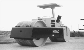
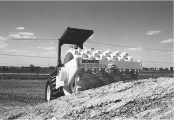
Two-Wheel Smooth Rollers. The two-wheel roller is also known as a tandem roller. The standard two-wheel roller has same-width rollers in front and in the rear. It may have equal-diameter wheels; or the front, steering one, may be a little smaller in diameter. Weights are usually between 2 and 15 tons (1.8 and 13.6 metric tons), but both smaller and larger rollers are available. The rear drive wheel carries about 60 percent of the roller machine’s total weight. An example of this compactor, which may incorporate vibratory action (explained later), is shown in Fig. 19.36.
Weight can usually be increased substantially by filling the roller wheels with water or damp sand ballast. If the descriptive rating for a machine has two figures, for example, 10-14 ton (9.1-12.7 metric tons), the first represents empty weight and the second the maximum weight with ballast added. The drive roller, which carries more weight, will produce considerably greater compression on the surface the machine is compacting. Compression produced is measured in pounds per linear inch of roll width.
FIGURE 19.36 Two-wheel static roller. (Courtesy of Compaction America, Inc.)
Clutch and Transmission. A roller drivetrain must be designed so that starting, stopping, and reversal of direction can be done easily and with great smoothness. Rough or sudden response to any of these actions tends to cause shifting of material and overcompaction under the drive rolls.
In gear drive, a reversing clutch is teamed with four speeds. Models with torque converters have two speeds, whereas hydrostatic drive has either two speeds or one speed. All speeds are reversible. The upper gear(s) is (are) generally only for travel. The brake is usually inside the transmission. With hydrostatics, most stopping is done automatically by the drive transmission.
Hydrostatic Drive. In hydrostatic drive, a variable-displacement, reversible piston pump is mounted on the engine output shaft. It drives a similar, but usually fixed-displacement, motor geared to a simplified transmission, which may be one-speed or two-speed.
This mechanism, which was discussed in Chapter 12, provides smooth reversing of direction and a stepless change of speed ratios, from zero to maximum speed at the throttle setting, by movement of a single lever. It also provides dynamic braking when in neutral.
Guide Roll and Steering. The front or guide roll is made up of two sections which turn independently. It is connected by a yoke and a horizontal hinge to an overhead kingpin. See Fig. 19.37. The weight of the frame is carried on roller bearings on the kingpin shoulder, and the kingpin itself is kept in line by tapered roller bearings. Steering is by means of a two-way hydraulic ram, acting against a lever clamped to the kingpin. Extending the ram turns the steering roll to the left, retracting it, to the right.
The rolls are equipped with scraper blades, two to a wheel, which are held in light contact with the surface by springs unless locked out of contact. These are essential to prevent material from sticking to the roll and building up so as to spoil the smooth surface.
The roller may be equipped with a sprinkling system. This consists of a tank, valves, and piping to the wheels. At each outlet the water trickles over a cocoa mat, a fabric of wood fibers that distributes the water as a film of moisture over the entire roll surface as it turns against it. The mats are swung out of contact when not in use.
Scarifier. A scarifier is a common accessory. Its base frame is bolted to the rear of the roller. The teeth are mounted in individual arms, fastened to a shaft which is raised or lowered mechanically or by a two-way ram hinged to the carrying frame. See Fig. 19.38. A pair of wheels which ride on the surface limit the depth to which the unit can be depressed. Depth of penetration is also regulated by setting the teeth up or down in their clamps, and by holding the wheels above the ground.
A roller has rather weak traction, so in order to do effective scarifying, it usually is necessary to put teeth or lugs in the driving wheels, in tapered sockets provided for the purpose. These sockets are normally filled with plugs flush with the roll. Use of spike teeth not only gives good traction, but damages the surface so that the scarifier has an easier job breaking it.
Portables. There are a number of light tandem rollers, 6 tons (5.4 metric tons) or smaller, that are “portable,” that is, they can be towed as semitrailers. They have a pair of rubber-tire wheels that are held up out of the way during work, but can be lowered to support them when towed behind a truck.
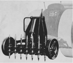
FIGURE 19.38 Hydraulic-lift scarifier.
FIGURE 19.39 Trench roller compactor. (Courtesy of Compaction America, Inc.)
In the simpler models, the wheels are moved from upper to lower positions manually, after driving one roll up a ramp or bank. In others, they are shifted hydraulically.
In either case, the wheels carry part of the roller weight when they are lowered, causing the guide roll (which is the lighter end) to rise off the ground.
Before lowering the wheels hydraulically, a towbar at the drive roll end is attached to the pintle (tow) hook of a truck. It is forced down hydraulically to lift the drive roll, so that the roller is supported on the rubber tires and the towbar. It can then be towed at moderate highway speeds.
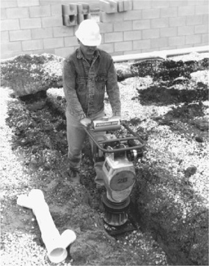
Trench Rollers. Trench rollers are used for compaction of backfills in ditches and for road widening when the strip is narrow. The rollers may be 15 inches (0.38 m) to 3 feet (0.91 m) wide and have a static weight of 1,000 to nearly 3,000 pounds (454 to 1,360 kg). They may not be smooth rolls, as seen in Fig. 19.39. To get more compactive effort, this type of roller generally has a vibratory mechanism to produce the equivalent of 1 to 6 tons (900 to 5,400 kg) of force. The vibratory mechanism will be discussed in a following section.
Controls. So far as the controls are concerned, roller operation is simple. With either torque converter or hydrostatic drive, there is only one gear for working speeds, and probably another for travel. The forward-reverse lever, the steering bar or wheel, the throttle, and sometimes the brake are all you have to use.
Modern machines have hydraulic steering. If there is a steering wheel, control resembles that of an automobile.
Units steered by a tiller or steering bar are turned by moving the bar in the direction of turn until the front roll is at the angle desired. The bar is returned to center until the turn is completed, moved to the other side until the front roll is straightened out, and is then returned to center. Any adjustments in sharpness of turn may be made by moving the bar one way or the other.
The error to be avoided is that of leaving the bar in the side position, as one would a car’s steering wheel. This causes the ram to continue to move, making the angle sharper and sharper until the stops are reached.
A differential lock is not used during compacting work. It is intended to give additional traction when scarifying, or walking over rough or steep ground.
The sprinkling system cannot be used in compaction of subgrades, as dirt or gravel will stick to the wet rolls and come up in chunks, spoiling the surface. If water is needed for the compaction, it should be supplied by water wagons sufficiently in advance that it can dry slightly before the roller reaches it.
Stopping. Stopping and starting should be done gradually in order to avoid scuffing of the surface. It is best to disengage the clutch before reaching the end of the run, so that the roller can drift to a stop without using the brake or reversing the clutch. When it is stopped, the clutch for movement in the opposite direction is gradually engaged for a smooth start.
Obstructions. Manholes or other obstructions in the road interfere with regular rolling patterns. The way they are handled will vary greatly with their height, construction, and location. In rolling up to an obstruction head-on, the clutch should be released or partially released before coming to it, so that the roll will just touch it without having momentum enough to break or climb it.
The pattern is rolled the first time as nearly normally as possible, and curving passes are made later. Spaces which the roller cannot reach without excessive maneuvering should be hand-tamped, or a smaller roller should be used in them.
Sequence. Rolling speeds are slow. One and a half to three miles per hour (2.4 to 4.8 km/hr) is usual.
The rear wheels of a roller do most of the compacting, particularly on the three-wheel type. The smaller and lighter front roll serves to “work” and stabilize the soil.
In rolling deep, loose material such as fill or gravel, all passes in a series except the first should be overlapped at least half the width of the drive roll. Gradual extension of the roller into the unrolled area makes possible greater concentration of weight on local ridges and high spots, and keeps the rolls running at a truer grade.
In rolling a graded area with a sideslope, as a crowned or banked road, work should always be done from the bottom up. The lower edges of the rolls have a tendency to push downhill, which can be best resisted by compacted material. In working uphill, the creep of soil away from the upper edge helps to preserve the slope.
A crowned road is rolled according to the pattern in Fig. 19.40, starting at one edge and working up until the center is reached by the upper roll, then moving diagonally to the opposite side and working up from there. Each rerolling is started at the bottom in the same manner.

ROLLING SEQUENCE ON CROWNED ROAD
overlapping not shown
FIGURE 19.40 Rolling sequence, straight.
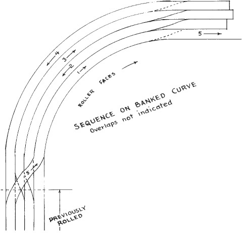
FIGURE 19.41 Rolling banked curve.
Banked or superelevated curves are rolled from the inner edge to the outer edge, Fig. 19.41. The transition from crown to bank is made by a diagonal from center to low side. From bank to crown the move is from either edge straight into the adjoining low side. The meeting of these two types of grade is a convenient place to end a rolling section, if the continuous-advance system is not being used.
Rolling should be continued until no advantage is noted from successive passes. Presence of too much water in the subgrade may make its compaction impossible, but long rolling will at least bring much of the water to the top where it can evaporate more readily. The waterlogged condition results in a rubbery action of the ground, in which it goes down under the rolls and springs back into nearly its original condition when they have passed. This condition may not be apparent at the start of the work, as the larger airspaces in the unconsolidated soil may be adequate to hold the water. As these spaces are reduced, however, the water is forced out of them and becomes a lubricant between all the particles.
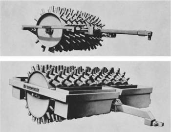
Tamping Rollers. Towed tamping or sheepsfoot rollers were for a long time the standard tool for compacting fills. They consist of steel drums fitted with projecting “feet” and towed by means of box frames. See Fig. 19.42. On a soft fill layer, the roll will compact the surface somewhat while the feet compress the base with greater force. As the soil becomes packed, the feet do not penetrate as far, and first lift the roll clear and finally walk themselves almost out of the ground.
Feet are usually from 7 to 9½ inches (17.8 to 24.1 cm) long. Two types are used. The original sheepsfoot has an enlarged, off-center sole and a straight shank. The tapered foot diminishes from base to sole and may be round, square, or angular. The sheepsfoot is easier to pull, but is liable to tear up the ground when backed, and compacts only below the sole. The tapered foot kneads and compresses soil laterally for its full length, and works as effectively backward as forward.
Two or more units can be combined in multiple frames. These are hinged to oscillating bars in the rear, and to tow bars in front. The towing tongue should be spring-cushioned to minimize shock to tractor and roller.
Cleaner bars are usually put on the rear of the frame to remove dirt caught between the teeth. If the roller is to be used extensively in reverse on sticky soils, it should have front cleaners also. Clogging destroys the effectiveness of the machine.
Individual rolls may be from 4 to 6 feet (1.2 to 1.8 m) wide and 3 to 5 feet (0.9 to 1.5 m) in diameter, not including the feet. They can be filled with ballast of water or sand, and may carry sandboxes in addition. Foot pressures range from about 150 to 750 pounds per square inch (10.5 to 52.5 kg/sq.cm), depending on the size of the unit and the amount and kind of ballast used.
A bulldozer may tow a tamping roller while spreading fill, so that both grading and compaction can be done by one operator.
Self-propel. Tamping rollers are now self-propelled. They may be specially designed machines, or four- or two-wheel-drive tractors with special wheels. These machines are usually center-articulated, with arrangements for rear wheel feet to step accurately between prints of the leading wheels, in forward or reverse movement.
Traction with four-wheel drive is commonly by rear axle oscillation, and it often is profitable for the machine to carry a dozer blade, for use in rough grading while compacting.
Self-propelled tamping rollers may have a working speed of 4 miles per hour (6.4 km/hr) forward and reverse. The long feet tend to kick out and loosen soil at over 6 miles per hour (9.7 km/hr), and thus limit working speed.
Shorter feet, or the pads described below, allow higher speed during compaction.
There are many tamping roller combinations. A single machine, usually articulated, may have a pair of rubber drive wheels and a tamping drum, a tamper and a smooth wheel, or a tamper and a vibrating roll. Usually, each has its own special uses, with an additional range of general applications.
The rubber or pneumatic tire roller substitutes a number of wheels and tires for the steel drums discussed so far. They add to their downward pressure a kneading effect, as material is pressed toward spaces between tires.
Wheels are mounted in pairs that can oscillate, or singly with spring action, so that tires can move down into soft spots that would be bridged by a drum. There may be means to lock out individual movement for special work.
The typical rubber-tire roller is a weight box mounted on two rows of tires in tandem. See Fig. 19.43. The rear row may have an even number, the front an odd number of wheels. They are aligned so that the rear tires more than cover the spaces left between front tire tracks.
Ballast in the boxes is usually dry, and almost anything will do. Sand, gravel, stone, and/or chunks of metal are used.
These rollers may be trailers. More often, they are self-propelled with (usually) torque converter, reversing clutch, and two to four speeds each way. Final drive may be gear drive or hydrostatic. Top speeds may be 15, or over 20 miles (24 or over 32 km) per hour. Weights range from about 5 to 35 tons (4.5 to 32 metric tons).
Rubber (pneumatic) tire rollers are successful in most types of compaction work, from raw fills to asphalt surfaces. The tires, which are usually smooth tread, may be fitted with scrapers for sticky soil.

FIGURE 19.43 Rubber-tire roller in action.
Vibration. Vibration of a tool in contact with the ground produces a rapid series of impacts that develop pressure waves which penetrate the soil, setting its particles in motion. If the tool exerts static pressure, the combined effect will be to rearrange the particles, and force them into a compact structure with a minimum of voids.
Vibration is usually produced by rapid rotation of an axle carrying off-center weights, called eccentrics. It is transmitted to the vibrator parts through ordinary bearings, and insulated from nonvibrating parts of the machine by pads or hangers of flexible material, called isolators.
Measures of vibratory motion are frequency and amplitude. Frequency is in cycles per minute, and depends on the rotation speed of the eccentric axle. There may or may not be means to change frequency during operation. See Fig. 19.44.
Frequency available in rollers ranges from a few hundred vibrations per minute (vpm) to 3,200 or more, but in any one machine, the range usually is much smaller.
Amplitude is the distance of movement of the vibrating surface from a central position. It is half the total movement. It varies with the elastic and damping properties of the soil, but may be given a nominal rating, neglecting soil effect.
In some machines, amplitude may be adjusted by transfer of fluid between rotating chambers, one of which adds to off-center weight, while the other counterbalances it.
In general, increase in a compactor’s ground speed calls for faster vibration. Otherwise, there is a great deal of contradictory evidence about the relative advantages of various speeds.
Most soils have a resonant frequency at which they vibrate most readily. A vibrator in contact with the soil will develop its greatest amplitude at that frequency. Some authorities consider that best compaction is obtained at resonant frequency, while others consider it less important.
Dynamic force is the centrifugal force produced by the eccentrics. In a general way, it represents the power behind the vibratory stroke.
Vibration in Rollers. A roll vibrates if it is mounted on a vibrating axle. The axle turns in end bearings supported in vibration-damped brackets on the frame, and in another set of bearings on which the roll revolves.
The roll vibrates with the eccentric, and may be called the vibrating mass. The frame and the engine have little vibration, but their weight is essential to the effectiveness of the roll. They may be called the surcharge.
An eccentric may also be turned by a hydraulic motor and V-belt, substituting flexible hose for belts and couplings, and providing means for control of frequency independent of engine or travel speed, and for reversing rotation of the eccentrics. This reversal may be made automatic when direction of travel is changed, to reduce sinking and scuffing.
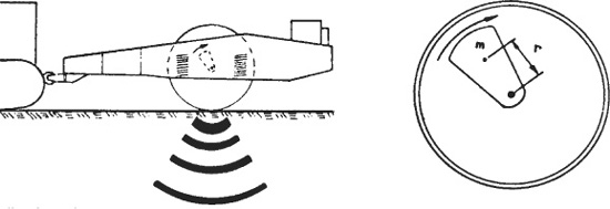
FIGURE 19.44 Vibration, and vibrator.
FIGURE 19.45 Vibratory tamping compactor. (Courtesy of Compaction America, Inc.)
Many vibratory rollers are of articulated construction, with an engine and control section driving by means of a pair of large wheels, which usually are rubber-tired but may be steel drums, smooth or with tamping or pad feet. The other section is a drum roller, smooth or otherwise, with a vibratory axle turned by a hydraulic motor.
Vibrating rollers usually give best results when moving slowly, from 1½ to 7 miles per hour (2.4 to 11.3 km/hr). They will provide some compaction at higher speeds, but must usually do the same area a greater number of times. See Fig. 19.45.
Vibration greatly increases roller effectiveness on loose, granular soils, but makes little difference on silt and clay. The rule of thumb is: The larger the grain, the greater the effect. Comparisons between vibratory and static rolling are therefore of little value unless the soil type is specified.
Under favorable soil conditions, a vibrating roller may produce compaction equivalent to that of a static roller 2 to 4 times as heavy. Some of them are therefore very small, even so small that the operator walks alongside instead of riding.
It is often not practical to use rollers against walls, between manholes, in ditch bottoms, and many other places where space is restricted.
Soil in such spots is compacted by tamping. Considerable benefit can be obtained by walking or stamping down 2- to 3-inch (5- to 7.6-cm) layers, or pounding with sledges or other tools.
Hand-Operated Rammer. Mechanical tampers, which may be operated by gasoline, air, or electricity, may operate by jump pounding, by leaving the shoe on the ground and hammering it, by vibration, by combined hammering and vibration, or by weight dropping.
FIGURE 19.46 Rammer compactor. (Courtesy of Vibromax America Inc.)
The rammer, Fig. 19.46, includes a single-cylinder, two-cycle engine. The working piston is attached to the foot. This type of machine weighs more than 100 pounds (45 kg) and is operated at the rate of 800 to 3,000 blows per minute, with jump strokes of 1½ to 3 inches (3.8 to 7.6 cm) off the ground. Tilting it slightly in the direction of the desired motion while working will cause it to walk in that direction.
Compaction Meter. There is a patented Compaction Meter available from MBW that takes the guesswork out of backfilling a trench to the required compaction. Using a very inexpensive, disposable sensor placed at the bottom of the trench with an attached wire long enough to reach the surface, the backfilling can begin. As the earth backfill is placed in lifts and compacted, the readout meter attached to the upper end of the wire tells by a red light when the lift has been compacted to a set design level, say 95 percent of optimum density. The required design level of compaction can be field-calibrated to any specified level for the backfill. When the backfilling is completed to the top, the wire is cut off at the surface and only the sensor at the bottom of the trench plus the depth of wire is not recovered.
Vibrating Plate Meter. The hand-operated plate tamper, like the one in Fig. 19.47, has a gasoline engine that operates a reciprocating-type vibrator, with frequencies between 4,000 and 6,000 vibrations per minute. It has a very short stroke.
The machines weigh from 400 to 1,500 pounds (182 to 681 kg). Working depths depend largely on soil characteristics. Compaction may be obtained for some distance around the plate, by vibratory settling. The machine is designed to move forward or in reverse as controlled by the operator.
FIGURE 19.47 Vibrating plate tamper. (Courtesy of Compaction America Inc.)
Traveling Vibrator. This flat vibrating unit, Fig. 19.48, is primarily intended for compaction of blacktop, loose granular soils, clean gravel, and crusher rock.
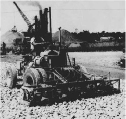
FIGURE 19.48 Vibrating compactor.
FIGURE 19.49 Use of compactors. (Courtesy of Vibromax America Inc.)
These machines move themselves along the working surface at speeds of up to 30 feet (9.1 m) per minute, when hand-operated. They can also be mounted in gangs held in a lift frame on a tractor, which is also equipped with a generator to provide current for them.
Compactor Selection. Since soils are usually mixtures of granular and fine-grained soils, compactor machine selection becomes more of a problem. Generally, the machine used should be the type best suited for whichever soil material predominates. The graph in Fig. 19.49 shows application of this approach.
Vibratory Probe. Sandy soil may be compacted to depths of up to 60 feet (18.3 m) by means of an open pipe clamped in a pile-driving vibrator. This is sunk and withdrawn vertically at calculated intervals, usually 4 to 10 feet (1.2 to 3.0 m), in a square grid pattern over the area to be stabilized. See Fig. 19.50.
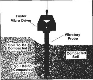
Vibration packs the soil particles closely together, and forces excess water out of the top of the formation. If the soil type is suitable, compaction can be accomplished underwater.
Power-Down Hammer. Newer portable hammers may use hydraulic pressure to supply power for the downstroke, as well as for the lift. The hammer in Fig. 19.51 may operate on the rear of either a truck or a tractor.
The truck is much faster and more convenient when moving between jobs, while the tractor is more maneuverable.
This model has a downstroke force that is adjustable by the operator to an impact force of from 80 to 16,000 pounds (36 to 7,300 kg). Cycle can be varied from 0 up to 110 strokes per minute. This tool is used to compact and stabilize deep, narrow fills, as in trenches. It can be fitted with tools for breaking pavement (illustrated) or boulders.
Dynamic Deep Compaction. The process of heavy weight dropping in order to modify the load-bearing condition of the ground is called dynamic deep compaction. On one site, two cranes lifted and dropped 10- to 20-ton (9,100 to 18,200 kg) weights in a grid pattern covering a 83,000-square-foot (7,700-sq.m) building area. The dynamic deep compaction procedure densified the soil so much that the ground surface after debris recompaction was about 3 feet (0.91 m) lower than the original surface.
The dynamic impact of a heavy weight dropped from heights of up to 150 feet (46 m) transmits shock waves downward through the soil. Dropping weights like this on the surface is practical for soil depths of up to 100 feet (30 m). Most soil types, even silts and some clays, can be helped by this process. For treatment of cohesive soil, careful planning and field control are mandatory. Between weight drops, high pore pressures must be allowed to dissipate. This can be accelerated by using sand wick drains.