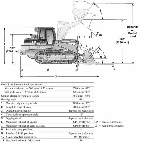
A machine developed from the bulldozer might be called the front-end tractor shovel. This machine may also be called a shovel dozer, dozer shovel, tractor loader, front-end loader, or just loader. It is used for digging, loading, rough grading, and limited hauling.
A typical loader is shown in Fig. 16.1 including a support frame on a tractor, a hydraulic system, a pair of push or lift arms (the boom) hinged to the top of the support frame, a tractor-width bucket hinged to the front of the arms, and a pair of dump arms hinged both to the push arms and to the bucket. Nontractor movements are under the control of two pairs of hydraulic cylinders.
The loader may be carried by any type of tractor. Crawler and four-wheel-drive tractors are used for heavy service, and two-wheel-drive tractors for lighter work.
Crawler tractors that carry loaders are usually specially designed for them, and differ from standard models. Tracks may be wide gauge and made extra long, with an additional track roller on each side. The idler and sometimes the front roller are of extra heavy-duty design. Width is necessary for stability against side tipping when carrying high loads. The long tracks move the center of balance forward so that heavier loads may be broken out and carried. The heavier idler and roller construction is required by the heavy front loads.
Tractors redesigned to carry loaders do not have springs. Most of them have a rigid connection between the track frames and main frame at the front, thus improving stability at the expense of some operator comfort and grading control.
If drive is mechanical, the engine clutch must be rugged, as a loader is very hard on it. It is likely to have ceramic discs instead of lining, or operate in a circulating and cooling oil bath.
However, most loader tractors have torque converters, teamed with power shift transmissions. This construction avoids the problem of slipping a clutch, and improves lugging qualities in the bank. Power shift improves flexibility and shortens cycles.
Hydrostatic drive may replace the converter and transmission.
Loader Frame. The frame is composed of a massive weldment fastened to the track frames and/or the central frame. It carries the pivot or hinge pins for the push and dump arms and their hydraulic rams, and transmits the weight, thrust, and twisting strains of the loader to the tractor.
The frame connections or stress points should be inspected periodically, and tightened or welded as required.
Arms. The push or lift arms are hinged to the top of the columns or tower on the frame. They extend forward to hinges near the bottom of the bucket. A cross beam or other linkage braces them near the front. The arms-and-brace assembly may be called a boom.
FIGURE 16.1 Large crawler-mounted front loader. (Reprinted courtesy of Caterpillar Inc.)
Lift arms are raised and lowered by means of two-way cylinders in the bases of the columns.
In principle, the dump arms are a connection between the back of the bucket, above the lift arm hinges, and the columns. This connection includes hydraulic cylinders, whose lengthening dumps the bucket, and whose shortening rolls it back.
The actual mechanism is more complicated, to supply changes of leverage, stability, and/or a mechanical (parallelogram) linkage to automatically level the bucket floor as it is lifted. This last function may be taken over by hydraulic valve arrangements and controls.
Bucket. The bucket is of simple box construction. A heavy cutting edge of tempered steel runs along the front and partway up the sides. The upper back curves forward. It is placed as close to the tractor as possible, for stability.
Buckets are about the same width as the outside of the tracks. Present size range for standard weights ranges from 1 yard (0.76 cu.m) to around 4 yards (3.1 cu.m) for crawlers. Wheel tractors have both smaller and larger sizes, from 5 cubic feet (0.14 cu.m) to over 30 cubic yards (23 cu.m).
Buckets are made in different sizes and weights for various types of material and work conditions. Light material buckets for handling humus, sawdust, or snow may be from 40 to 100 percent larger than standard buckets. Rock buckets are heavily reinforced. Slat buckets are used for handling loose rock or wood. They allow unwanted dirt to fall away through the slots. See Fig. 16.2.
Teeth are standard equipment on rock buckets, and optional on standard weight. They help greatly in hard digging, and in handling rock, stumps, and brush, but they interfere more or less with grading. Their cost is partly offset by the protection they give to the cutting edge.
Design must be a compromise. The bucket should be strong enough to take any punishment the tractor can give it, but light enough to raise a big load without overbalancing the tractor and without absorbing too much of its lifting power.
Bucket Action. The standard bucket has three working motions. It is raised and lowered by two-way rams controlling it through the push arms, it is tilted or rolled between carrying and dumping position by the dump rams and linkage, and it is crowded and retracted by the forward and reverse travel of the tractor.
Dumping height is the elevation above ground level of the lip of the bucket in dumped position. It may be several feet (meters) below the height of the lip in carrying position, and 1½ to 2½ feet (0.46 to 0.76 m) below the bucket hinges. Maximum dump height varies from 7 to 10 feet (2.1 to 3.0 m), being greatest in the larger and newer machines.
The bucket will usually tilt nearly 100° between dump and full-back positions. See Fig. 16.3. At maximum height the dumping slope of the bottom is 45 to 50°. At ground level a bucket may be kept fully dumped for float-grading while moving forward.
A bucket is said to be rolled, tilted, or curled when the floor is tilted so as to retain a load.
The standard Society of Automotive Engineers’ (SAE) breakout force of a tractor to dig material is less than its operating weight. This is necessary; otherwise, the tractor would be lifted out of its position. There are several aspects of the tractor that lead to a strong breakout force. Obviously, the engine and hydraulic power contribute. Another is the linkage between the push arm and the dump arm of the bucket. It is claimed that a Z-shaped linkage, shown in Fig. 16.4, can produce better breakout force. This linkage is compared to the parallel linkage seen in Fig. 16.3, which does a good job of keeping the bucket in a level position while it is being raised and improving its reach.
When a bucket is rolled back during penetration into soil, it pivots on its heel (rear of the floor) as a fulcrum, usually developing much more breakout force than can be provided by the hoist.
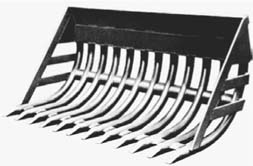
FIGURE 16.2 Slat loader bucket.
FIGURE 16.3 Representation of medium-size articulated wheel loaders.
Rollback is also useful in slicing upward in hard or heavy banks. It makes it easier to pick up heavy, heaped, or sloppy loads, and oversize objects. They can then be carried at a safe level, 2 or 3 feet (0.61 or 0.91 m) above the ground.
There should be an indicator on a loader arm to show the tilt of the bucket, as this is usually difficult for the operator to observe directly. Its usefulness may be improved by a paint mark, a strip of bright tape, or a weld tack at level-on-the-ground position.
Automatic control of rollback will be discussed under OPERATION.
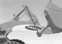
FIGURE 16.4 Z linkage between lift boom and bucket. (Courtesy of Samsung Construction Equipment Co.)
Rolling back is useful in slicing upward in hard or heavy banks, and in picking up and carrying heavy, heaped, or sloppy loads, and oversize objects. It improves balance by moving the load toward the tractor.
Hydraulic Systems. Loader hydraulic pumps are designed for flow capacities varying from 12 gallons (45 liters) per minute for small loaders up to more than 100 gallons (379 liters) per minute for the largest loaders. The relief pressure is from 2,000 to 4,500 pounds per square inch (140 to 315 kg/sq.cm). Most loaders, regardless of size, have a load-sensing system for both the hydraulic systems and transmission. For instance, a fully automatic transmission will have preset shift points, so that shifting occurs at optimum torque.
The reservoir, holding more than the maximum gpm required of oil, is equipped with filters to remove outside dirt and products of wear. It may be a closed system, or an open one with a filtered air vent. It is important to keep oil at the proper level. Too little will allow the system to suck air and perform jerkily, too much may cause squirting out of the vent or building up of damaging pressure when lowering a loaded bucket.
Hoist and dump are controlled by two-way-type levers at the right of the cockpit. The hoist lever may have four positions, FLOAT at the front, then DOWN pressure, HOLD, and UP at the back. To control the bucket, a lever has three positions: a center position to lock it against change in tilt, one to dump it, and one to rotate it back.
The control levers, which produce electronic signals, may be just 3 inches (7.62 cm) tall. These signals are received by the machine’s microprocessor, which activates the required hydraulics.
The control bank may carry an additional valve and lever, for use in operating a multipurpose bucket or a rear-mounted ripper.
Counterweight. On a small machine, 500 to 1,500 pounds (227 to 681 kg) will permit lifting and carrying heavier loads, and will improve traction when carrying a load. Larger machines can carry proportionately greater rear weights.
Counterweight may be a deadweight of metal or concrete attached to the back of the tractor, but is then most in the way.
The weight may also be a working part, such as a rear-mounted ripper, a power control unit, or a towing winch. The ripper enables the machine to break up soil in advance of grading or loading. However, the 7- to 30-inch (17.8 to 76.2 cm) layer of soil that can be reached by a ripper is not deep enough for efficient loading.
A counterweighted machine may be more difficult to steer with a load, as keeping the back down increases the track contact with the ground.
Track Shoes. Most crawler loaders have the semigrouser (three-cleat) shoes. Some have twocleat types.
When shoe surfaces are flat, the tracks will spin rather readily on many footings, giving the effect of a slipping clutch. This tendency to spin cushions all parts of the tractor against shock loads, but it often interferes with steering and traction and prevents the full power of the machine from being applied to its work. Semigrouser and other special, semiflat shoes give better traction but will still spin rather freely under slippery conditions. Full grousers grip well and aid in digging but make the machine very touchy and apt to stall, build up ridges behind the tracks, and subject machine and bucket to shocks and overloads that may shorten bucket life materially.
The chief objection to the use of grousers on a loader is that they tear up the ground when it turns, causing it to work itself down into holes that make work slow and sometimes dangerous. Flat shoes do this damage more slowly, or not at all if the ground is firm. Dirt loosened in this manner is easily smoothed off but will dig up again on the next turn. Under such conditions truck positions may have to be changed frequently to keep the loader on good footing.
Crawler Loader Costs. The majority of owners of crawler loaders larger than 105 hp (78 kw) spend the equivalent of about half of their original purchase price for repair parts and labor over the life of the equipment, according to the Construction Equipment Reader Advisory Board.
Operating conditions apparently favor undercarriage life. Those machines that operate about a third of their time on forgiving soil and gravel and only about 10% of their time working in demolition debris and shot rock fair best.
According to a survey of the owners of crawler loader machines, a majority get less than 35% of the original cost when reselling, although some get as much as 50% of the original price for their machines.
Wheel-mounted front loaders work on the same basic principles as crawlers, but there are a number of differences in size and structure. Uses are strongly affected by type of carrier.
The most important units for heavy work are mounted on four-wheel-drive tractors. See Figure 16.3. Smaller models are on skid-steer or conventional two-wheel-drive machines.
Dump rams and arms may be hinged on the columns above or below the lift arms, as in the crawler machines. But they may also be on the same hinge pins, or based on the lift arms themselves. In the two last cases, the bucket remains at a fixed angle with the lift arms as they are raised or lowered, unless changed hydraulically by automatic controls.
Four-Wheel Drive. The medium-size and large loaders on rubber are on articulated, four-wheel-drive tractors. See Fig. 16.5. Loader frame columns are forward of the swivel. Lift arms are therefore shorter than on the crawlers, and rise to a steeper angle for the same bucket height.
Most of these machines are equipped with torque converters and easy-shift or power-shift transmissions. It is important that the forward-reverse shift be of the clutch or power shift type, to avoid delays in meshing gears or synchronizing clutch and gears. See Figure 16.6.
Operators sit high and forward, where they have a good view of the bucket, but are exposed to danger of objects falling off its back. The engine is in the rear.
Even though the articulation turns to about 40°, turning radius is much longer than that of crawlers, so more space is required to maneuver from bank to truck and back. Faster travel and usually faster shifting keep cycle time as short as that of a conventional crawler.
In common with crawler-mounted loaders, wheel loaders can handle large boulders by carrying or pushing and can keep their pit area cleaned and leveled.
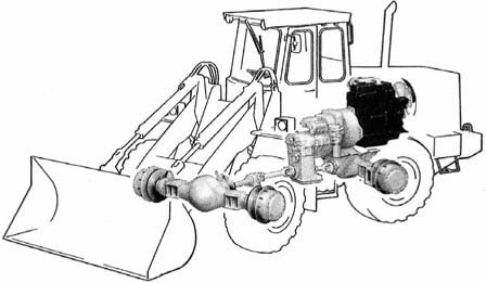
FIGURE 16.5 Power train, articulated loader.
FIGURE 16.6 Controls, four-wheel drive.
Wheel loaders have the outstanding advantage of quick and easy moving from one part of a job to another. They can also be driven from one job to another, but the bigger ones are so wide as to require special permits, and slow enough (30 miles per hour (48.3 kmph) or less] that trailers may be preferred on long hauls.
New machines such as Case’s 821E, which has a Tier 3 compliant diesel engine with a new hydraulic system, an auto-idle system, and other improvements use less fuel than the machine it replaces. The savings is in the order of 4% less fuel.
Very large tires are generally used. They serve to provide excellent flotation, permitting work on most footings. Ground pressure is still much higher than with crawlers, but the packing effect of the tires and the more gradual turns make it possible to work easily on sandy ground that would tear up under crawlers, and cause excessive track wear. But slippery surfaces may cause loss of both traction and steering accuracy.
Skid-steer loaders are small and very compact. See Fig. 16.7. Weights range from less than a ton (908 kg) to more than 4 tons (3,600 kg), with bucket capacities from 5 cubic feet (0.14 cu.m) up to 1½ yards (1.15 cu.m) for light material. Dumping clearance is 6 to 10 feet (1.8 to 3 m). Drive is usually hydrostatic, but may be by belts or chains.
The lift arms are pivoted to triangular columns behind the rear wheels, and extend alongside the tractor for its full length. The cab includes steel-mesh sides, to protect against operator en-tanglement with the arms. The entrance is at the front, across steps provided on the bucket.
Travel is controlled by a T-bar controller or a pair of hand levers, each of which causes its side of the machine to move forward or back, as the lever is moved. The loading part is operated by rocker foot pedals, Fig. 16.8. The center pedal is installed for auxiliary hydraulically controlled equipment.
FIGURE 16.7 Skid-steer loader in action. (Courtesy of New Holland North America, Inc.)
Skid steer enables these units to turn in approximately their own lengths. Combined with short wheelbase, this enables them to work comfortably in areas so restricted that many standard loaders could not even enter.
Pushing a lever forward causes the wheels on that side to rotate to move the machine forward; pulling it back reverses the movement. When both levers are moved the same amount in the same direction, the machine will move in a straight line. If one lever is moved more than the other, the machine will usually turn toward the side of lesser movement. See Fig. 16.9.
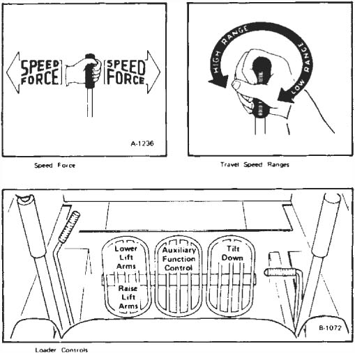
FIGURE 16.8 Travel and loader controls.
FIGURE 16.9 Steering controls, skid steer.
Ergonomic features are improving to help the operator of a skid steer more comfortably. These include low-effort controls, a comfortable arm rest, a retractable seatbelt, and a suspension seat.
If the levers are moved oppositely, one side will propel forward and the other backward, so that the machine will spin horizontally. In general, a machine with a loaded bucket will tend to slide the back wheels, with an empty one it will slide the front wheels. The actual movement is rather complicated, but the result is a U-turn in little more than overall machine length.
Small size and sharp turning enable these machines to work in very restricted areas. The drive to all wheels gives them good pushing power in proportion to weight.
Attachments. One of the important attractions for a skid steer unit of equipment is the variety of attachments it can handle. For earthwork the attachments include
• Front-end loader bucket
• 4-in-1 bucket (see figures later in this chapter)
• A variety of other buckets
• Dozer blade
• Hydraulic breaker
• Hole drilling augur
• Trencher
• Backhoe excavator mounted on back of machine
Quick coupling devices for changing buckets or other front attachments are available or may be standard with the skid-steer machines.
The compact loaders and excavators compare with the smallest skid steer units and larger excavators. They are generally less than 19,000 lbs (8,600 kg) operating weight with less than 100 hp (75 kw) and have zero to minimal clearance outside the track radius. Their static tip load is, generally, less than 12,000 lbs (5,400 kg). The compact loaders have been used for quite a few years in Europe but have been underutilized in North America. Only 10,000 compact excavators were sold each year in the United States through 1998, but nearly 30,000 were used in 2008 across North America.
Since 2006 these compact machines have grown up to using pilot joysticks and electro-hydraulic controls. In the Gehl compact excavators, the hydraulic drive motors have an automatic two-speed system that senses a load and downshifts to apply more power with the same hydraulics and pressure. Other machines have load-sensing hydraulics that optimize oil flow based on demand. The result is smooth operation and better fuel efficiency.
Compared to skid steer loaders of similar size, the compact loaders have shown faster truck loading and greater lifting capacity with more stability and less ground disturbance. The machine can be delivered with rubber tracks reinforced with steel, like Caterpillar’s C-Series loaders, with new steel undercarriage and steel-embedded rubber tracks, making them particularly rugged. Or they have rubber-tired wheels, like Bobcat models, which enables them to reach 9 to 13 mph (14.5 to 21 km/hr) speed with 20 to 30 hp (15 to 22 kw) engines. The rubber-tired machines have operating weights of 2,000 to slightly over 3,000 pounds (910 to 1360 kg).
The manufacturers of the compact excavators have built in some of the comforts enjoyed by operators of the full size excavators. Heating and air-conditioning are included in compact machines ordered with a cab.
There are a variety of attachments that can be connected to a skid steer loader. These include a laser equipped grader (see Figure 16.10), trenchers, brush cutters, log or rock grapplers, rotary tiller, and a hydraulic breaker. The attachments make a skid steer or compact loader a very versatile piece of equipment for all sorts of jobs. So the basic machine can be used essentially 100% of the time.
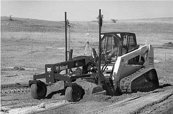
FIGURE 16.10 Laser-equipped grader.
Two-wheel-drive loaders depend on good traction to dig competently. A large machine, equipped with a backhoe or a heavy rear implement, can give an excellent account of itself in medium digging, if the ground is neither slippery nor loose sand. But poor ground or really hard digging make its work difficult and uneconomical.
These machines, as seen in Fig. 16.11, are excellent units for general helping and cleanup work. In yards, they can load crushed rock and other stockpiles just as well as four-wheel- drives.
Design is usually simple. Side frames are fastened to the rear axle housing and the sides of the radiator base, and columns, cross-braced to each other, are erected on the frames. Lift arms hinged on the column tops extend forward of the radiator guard to the bottom hinge of the bucket. These are between the hood and the front wheels when lowered. Double-acting hoist rams are hinged on the column bases and push upward and forward against the arms.
The dump rams are hinged to the lift arms. Their piston rods are extended into dump arms that hinge to the upper back of the bucket. The pump is driven from the front of the engine. A single two-section control valve regulates movements of the hoist and dump rams. The standard bucket is box type, straight-edged with an option of teeth, and as wide as the rear wheel tread. Other widths are usually available.
Bucket Angle. Most loader digging is started with the floor flat or tilted to a slight downward angle. This position gives maximum penetration into banks and high spots, and cuts a smooth path on which the tracks can follow.
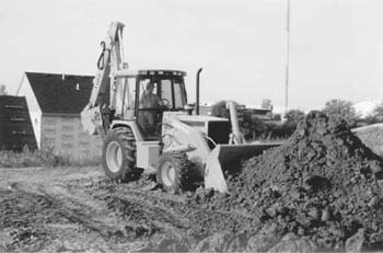
FIGURE 16.11 Two-wheel-drive loader and backhoe. (Courtesy of Deere & Company.)
A rollback bucket is fitted with an indicator by which the operator can tell its angle of tilt. The operator may adjust it to flat position by reading the indicator, or by observing the bucket directly.
Cutting Down. For cutting down into a level surface, tip the bucket downward 10 to 30°. When it has penetrated to a depth of 2 to 6 inches (5.1 to 15.2 cm), it should be turned up to a flat or almost flat position, while the forward motion of the tractor is continued until the bucket is filled.
This tilt sequence combines good original penetration, sturdiest position of the bucket for most of the pass, and a powerful prying effect during the change in angle. Under some soil conditions continual minor adjustment of the angle while digging helps penetration.
The flat position is best for pushing a quantity of loose dirt, but the bucket should be turned down steeply for spreading and grading it, so that dirt will flow freely off the floor into holes, and so it will not be pulled down by sticky soil. Care should be taken not to hook into solid obstructions at a steep angle, as the bucket is then in its weakest position, and leverage against the dump mechanism is at its maximum.
Penetration. The loader bucket has much weaker penetration in proportion to size than a front shovel, because it is larger in relation to the power and weight of the machine, has a wider edge in digging, and may lack teeth. Another digging difficulty is that the hoist is slow in proportion to the speed of the tractor, so that the bucket tends to get under more dirt than it can break loose and lift.
Digging Banks. A standard method is to use low gear range to force the flat bucket into the bank toe at ground level. When resistance slows the tractor, the bucket is rolled back gradually and hoisted, while crowding with the tractor is continued. See Fig. 16.12.
Rolling back the bucket as it rises in the bank increases cutting efficiency by aligning the edge with its upward movement, and by retracting it for a thinner slice. Its own suction, and crowding by the tractor, tends to make the cut thicker.
The proper balance among these forces varies with the machine, the bank, and the position and momentum of the bucket. It is the operator’s responsibility to balance them so as to get a good bucket load in minimum time.
If the bank is hard, a thin slice may be most productive. If it is vertical, no crowding may be needed after initial penetration. If it slopes away from the loader, more crowding and less rollback are needed.
In general, a nearly vertical cut face in a bank not more than a foot (meter) or two higher than the lift arm hinges is most efficient for fast loading. This is called the optimum depth.
If the bank is higher than this, and overhangs, the upper part should be nudged with the full bucket occasionally to bring it down. See Fig. 16.13. But if the overhang is substantial, dig somewhere else.
If the loader has a self-leveling device, it may be necessary to cut it off, or to override it, to keep proper tilt in the bank. If it does not have it, you must remember not to give the bucket a high lift in full curl-back position, as this is likely to spill part of the load over the back—and probably on you.
If the bank is only 2 or 3 feet (0.6 or 0.9 m) high, it may be dug by keeping the bucket at final grade and running beside the bank, cutting into it as much as possible without slowing the tractor excessively. The cutting will be done by the side and floor of the bucket which is in the bank. The soil will roll along the bucket and fill it, although the load will be heavier on the bank side.
The tractor with a torque converter meets resistance in the bank that will affect tractor speed much more than hoist speed. Even with the tracks or wheels stalled, the engine loader’s hydraulic pump should maintain good speed.
This has the favorable effect of slowing crowd speed relative to hoist. However, the crowding force is increased by multiplication in the converter, so the bucket is still likely to be crowded into more dirt than it can lift.
Converters cannot be operated at full throttle under stall or near-stall conditions for more than a few seconds without excessive heat buildup and strain.
FIGURE 16.12 Bucket movement in bank.
If the throttle is cut back to idling speed, the torque converter will exert almost no drive force. The loader pump will be slowed, but it will continue to exert full pressure to lift the bucket at a slower speed. This combination favors breaking out an overloaded bucket. Part throttle weakens drive without stopping it.
The wheel-mounted loader may be operated with the hand throttle closed, so that the engine governor setting is controlled by a foot accelerator. The operator cuts engine speed by lifting his or her foot.
Some four-wheel-drive loaders have an engine (input) clutch in addition to the torque converter. This clutch is power-released when you press one of the brake pedals lightly, or touch a separate pedal. This permits disconnecting the drive (crowd) without slowing the engine or the hoist.
The crawler usually works with the hand throttle wide open. A decelerator (opposite of accelerator) pedal is depressed to slow it down. This is the pedal to push when you start to get stuck in the bank.
The separate responses of push and lift to load and throttle are the chief features that distinguish torque converter operation.
Payload. The amount picked up in the bucket varies with the type of bucket, the power behind it, the traction, the nature of the material, and the skill of the operator.
For each yard of bucket capacity, you might pick up anything from ½ to 1½ yards (0.38 to 1.15 cu.m), and should average ⅞ yard (0.67 cu.m) in medium digging. A bucket must be rolled back to carry its maximum load.
FIGURE 16.13 Loader working in high bank.
When dumping close to the digging point, as in sidecasting, or loading a properly placed truck, keeping up a fast cycle is usually more important than getting maximum loads with each pass. As distance to the dump point increases, capacity loads become more important than the time taken to get them.
If the load must be carried over rough ground or backward up a slope, it should be limited to the weight the machine can carry easily without tipping.
If the bucket does not fill sufficiently, the tractor should be backed up, the bucket lowered to floor level, and another pass made. If the load is one-sided, the second cut should be made at an angle to the bank so that the empty side will penetrate first.
It is often difficult for the operator to judge the amount in the bucket, unless the digging is easy enough to permit dirt to be forced over the top. It is a good idea to cut a row of holes, about 1½ inch in diameter, in the upper back of the bucket, through which the operator can see whether it is filled. Spillage through such holes is negligible in ordinary digging.
Ramping Down. If the digging is downward, as in cutting a basement or a ramp, hard material may require pitching the bucket floor at a 20 to 30° angle to the line of the tracks, and cutting in thin slices. The downward pitch of the ramp should be gradual, as the machine is nose-heavy with a loaded bucket.
Gouging. A common difficulty in digging heavy soils is that the penetration of the bucket is too good, so that it will be pulled down by the slice it has dug, either raising the back of the tractor or pulling the front of the tracks down into the ground. This may be combatted by keeping the bucket as flat as possible, or by tipping the floor into a nearly vertical position, which cures the difficulty but puts extra strain on the bucket.
It is often best to let it gouge, and make an extra pass to grade off the area as often as necessary.
Transporting. If the ground between digging and dumping is hard and smooth, backing, turning, and dumping can all be done at speed with safety. If the ground is rough, the machine must move slowly, as going over a bump or ridge with a heavy load may cause it to fall forward, the bucket dropping to the ground and the operator’s seat rising into the air. If part of the load dumps, the tractor will settle back. In crossing rough ground the operator should be alert to lower or dump the bucket if an upset starts. Lowering has the effect of taking the bucket weight off the tractor long enough to enable it to recover its balance.
Dropping a loaded bucket and stopping it abruptly in the air may burst a hoist ram hose if it does not overbalance the machine.
With crawlers, you cross ridges at such an angle that one track will be partway across before the other reaches it. If the ridge is soft, it may be possible to cut a more level path through it by turning sharply while on it.
If the bucket is carried 2 to 4 feet (0.6 to 1.2 m) above the ground, the consequences of over-balancing are unlikely to be serious. If it is high, the weight is not quite so far forward, so tipping is less likely; but if it occurs, it will give the operator a worse toss. A high-held bucket also involves the danger of less likely but far more serious side tipping.
This discussion is based chiefly on popular-size loaders with buckets from 1- to 2½-yard (0.76–1.91 cu.m) capacity. See Fig. 16.14.
Procedures for the actual digging in the bank are the same as those already described.
Maneuvering. The normal cycle for truck loading is made up of digging in the bank, backing out and making a partial turn toward the truck, then moving forward to the side of the truck while completing the turn and raising the bucket to clear the truck body.
The bucket should be high enough that the downward movement of the bucket lip during dumping will not cause it to strike the truck, and it is good practice to have it high enough to clear the side to avoid an accident while backing (contrary to the bucket height in part 3 of Fig. 16.14). The hoist is usually completed before the truck is reached. The control is then moved to HOLD, and the tractor moved so that the bucket is over the truck body.
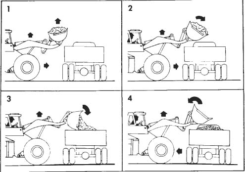
A good procedure is to time the lift so that the bucket will just safely clear the truck as it is moved over it and the control can be left in UP using the dump. These levels can be automatically controlled by preset electronic controls.
The tractor is walked forward until the bucket is as far over the body as desired or until the radiator guard touches the truck body or tire. The main clutch is released (or, with nonclutch converter drive, the throttle closed), the tractor held with a brake, and the control moved forward to dump the load. The first bucket or two are best dumped slowly to reduce shock to the truck. If the soil is sticky, the bucket may be shaken by banging against the dump stops by moving the dump valve lever rapidly back and forth.
The loader is shifted into reverse and backed away, the bucket lip being raised to clear the body if necessary. When clear of the truck, the machine is stopped, put in the forward gear for digging, and headed toward the bank, the bucket being put in digging position and lowered during the return trip.
Front-end-loader cycle time varies all the way from 20 to 50 seconds. Average with small machines is about 25 seconds, with big ones 35 or more. But in rough digging a big machine may have the shorter cycle.
Easy digging, good truck spotting, and power shift favor fast cycles.
Figure 16.15 shows the result of a study of cycle time in big wheel loaders.
Spotting Trucks. There are many possible patterns of digging and dumping. Figures 16.16, parts (A) and (E), show the most-used methods, in which the side of the truck is at right angles to the face of the bank. This involves a quarter turn twice in each digging cycle. The turning stress is high.

FIGURE 16.15 Cycle time, big front loaders. (Courtesy of U.S. Department of Transportation.)
In (B) the truck is parked at an angle of about 45° to the bank, so the loader’s turns are only half as sharp. In this position some loads can be swung from the bank onto the truck with a very short backward movement, thus increasing loading speed. This is the best system for tracks, but because of driver resistance and indifferent supervision, it is little used.
In (C) the truck is parked parallel with the bank, and the digging is done just behind it. This involves about the same amount of turning as (B), with a greater amount of walking.
In (D) the truck is parallel to the bank but at a distance from it, so that the tractor must make a 180° turn each time to put the load in the truck, and 180° to head back to the digging. More walking is required than in other methods. This is the slowest and most unsatisfactory of the arrangements suggested, but is often used in muddy or sandy pits where trucks are restricted to certain drives.
Figure 16.16(E) shows the effect of counterrotating tracks (or wheels) in shortening travel.
For wheel loaders, extra travel distance from bank to truck, up to 50 or more feet (15.2 or more m), may not consume time because of more maneuver space and use of higher gears.
Loader output can usually be increased substantially by having a spotter place the trucks, or by training the drivers to be alert to the needs of the machine so that they will not only take a convenient position, but be ready to move if the machine works away from them. This last is particularly important where the digging is shallow and truck bodies are large.
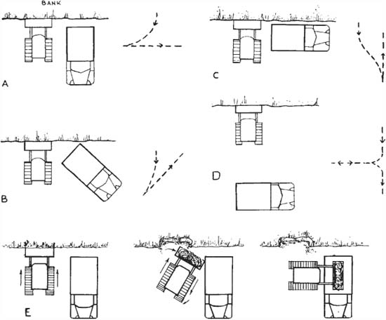
FIGURE 16.16 Truck patterns for front loader.
Dumping in Body. The width of standard buckets varies with machine width, usually from about 6 to 11 feet (1.8 to 3.4 m), but a few up to 30 feet (9.1 m). Truck bodies (including trailers and off-the-road models) vary from 7 to over 25 feet (2.1 to over 7.6 m).
Dumping height of the bucket, measured from the ground to the lip of the bucket, held at maximum height with the floor inclined downward at 45°, varies from 8 to 12 feet (2.4 to 3.7 m), in a few cases going as high as 20 feet (6.1 m). Highway dumpers have side heights of from 5 to 10 feet (1.5 to 3.0 m); off-the-road loaders may be over 15 feet (4.6 m).
Ordinarily, loaders are matched in size to the trucks that they fill. However, it is often necessary to cope with a mismatched set.
If the loader is too big for the truck, care must be taken to pour the load gently into the body, and allow excess to spill off the back.
A well-matched body can be fully loaded by dumping in the center only. A long body is loaded by dumping alternately in the front and rear from the side, although there is a tendency to pile up too much in the center and skimp the corners.
Such a body may also be loaded from the side at the front, and finished by filling from the rear, over the tailgate.
For convenience and efficiency in side loading, the sideboard of the truck should be a foot or two lower than the lip of the bucket in full-lift dumped position. This makes it easy to place the load in the center or even in the far side of the body.
High Trucks. If a body too high for convenience is loaded, a heaping pile of soil is built up on one side. This heap may be moved toward the other side by pushing it with a loaded bucket held with its floor parallel with the ground and just clearing the sideboards. The bucket is then dumped and its load pushed over by the next bucketful, this process being repeated until the body is full.
Dirt may also be worked over by putting the bucket in fully dumped position, dropping it just inside the body, and rotating it partway toward flat position.
If many big trucks are to be filled, it may save time to dig slots 2 to 3 feet (0.61 to 9.1 m) deep into which they can back while the loader operates on the higher level. If the pit floor must not be torn up, a few bucketsful will build a ramp up which the loader can walk to get an easy working height. The ramp should be made so that the machine is not tipped up steeply while dumping, as this reduces reach and increases the effort of holding position.
If there is uneven distribution of earth front and rear while loading, it may be corrected by cutting into the bank at an angle so that the side of the bucket which will dump over the low spot will get the heaviest part of the load. Dirt already dumped can sometimes be rearranged with the bucket in dumped position by pushing, pulling, or turning.
Distances. The loading is fastest if the truck is so close to the digging that the machine has just comfortable room to turn, although the hoist is not fast enough to lift the load to the required height in a very short travel distance. When a pit is too wet or sandy for truck operation, it can dig in the pit, carry material onto firm ground, and there put it in the truck.
Output. Figure 16.15 shows theoretical no-delay possibilities for large and very large wheel machines, based on United States Federal Highway Administration Report No. FHWA-RDDP-PC-520, “Production Efficiency Study on Large-Capacity, Rubber-Tired Front-End Loaders.”
Conditions get unfavorable much more easily for loaders than for shovel excavators, as their production diminishes more rapidly as the digging becomes harder or coarser, or the footing gets softer. On the other hand, an alert foreman and a good operator can often step up loader production way above average, simply by using sound procedures that are generally ignored.
When compared to a shovel of similar rate of production, the loader has the advantages of moving around more readily, cleaning up the pit floor and moving boulders without assistance, picking up bigger rocks without chaining, and use as a dozer while not loading. The shovel can handle harder digging, work on softer floors, and has lower repair and maintenance costs because its tracks and rollers have much less use.
A front loader that is mounted on a rear-drive tractor reduces its traction when it is carrying a load. The front axle acts as a balance point, and any weight ahead of it will counterbalance the weight on the rear wheels, sometimes to the extent of raising them off the ground. Any reduction in weight on the driving wheels reduces their traction, which in any case is not as good backing as going forward because of reaction from driving torque.
As a result of these factors, the machines cannot carry good loads on loose, slippery, or soft ground, especially in reverse. This difficulty may be reduced by heavy counterweights on the rear wheels or on the back of the tractor, by using dual wheels, or by attachment of a rear-mounted tool such as a ripper, a winch, or a scraper blade.
The rear tires should be filled with a water solution of calcium chloride, as discussed in Chap. 12. This is necessary for efficiency in any tractor work, and is the first step in counterweighting a loader.
If the load is carried very high, more of the weight will be on the rear wheels, although danger of side tipping is increased. Extra traction may be obtained for a moment by lifting the load high and letting it drop. While it is falling, the tractor is almost free of its weight, and the wheels may grip enough to get the machine moving. Sometimes the machine will be able to drag the loaded bucket backward on the ground or on skids.
Another consideration is that the front wheels normally carry less than half the tractor weight; but when the load is heavy, they carry most of the tractor and all of the load. This results in hard turning, particularly with large machines, in which power steering is a necessity. Front tires must be the heaviest offered with the tractor.
The two-wheel-drive depends on its momentum to drive the bucket deeply enough into the pile to pick up a good load. The speed required may be greater than would be safe for turning and dumping, and it is therefore desirable to have a foot accelerator by which the operator can speed it up as it approaches the pile without changing the hand throttle adjustment.
The pit must be arranged so that the machine will not have to carry a load while it backs uphill or across rough or sandy ground, as it is likely to lose time or be unable to work due to poor traction.
Direct digging of hard or firm soil can be made much easier by breaking up the ground with a ripper or subsoil plow, and cutting only to the depth the tool penetrates. Such a machine may be mounted on the rear of the tractor and serve for counterweight, or be a separate unit attached and pulled by the drawbar and detached during digging.
The large rubber-tire loaders may carry loads in complete-operation digging, hauling, and spreading, over distances up to ¼ mile (0.4 km).
Bucket capacity is smaller than in scrapers or trucks of comparable price, travel is slower, and the tipping influence of a loaded bucket limits them to well-graded routes.
They have an advantage over scrapers in being able to dig into banks from the floor of a pit or a cut, and in the ease with which they can build steep-sided stockpiles or dump over banks or into hoppers, without the help of other equipment.
A loader can supply a low or medium bin, saving either the expense of a truck ramp and hopper, or rehandling by clamshell. If the edge is a little too high, the loader can build a steep ramp of dirt or aggregate, as in Fig. 16.17.
If hauling is done by trucks, the loader (or an equivalent machine) is needed to fill them. A comparison graph such as that in Fig. 16.18 can be worked out, to determine the relative cost per yard of hauling by truck or by loader. If truck hauling requires a spreading or piling machine at the dump, its cost must be included.
The cost is not the whole story, however. The work may require more material than the loader alone can deliver, and there could be many reasons why the acquisition of an additional loader would not be justified.
FIGURE 16.17 Ramp up to a hopper.
Job simplification may also be important. Where one unit can do the work of several, problems of scheduling are cut. This factor may be particularly important in a small operation. The loader might be able to do this hauling, and also take care of other work, so that trucks could be eliminated without adding other costs.
Carry or Push. If material is to be moved a short distance, 200 feet (60 m) or less, and the quantity is large, it may be economical to push rather than carry it. A flat bucket floating on the ground, moving between windrows of spill, will move two to three times as much dirt or rock as it will carry. Loads may be even better if the push is downhill.
Disadvantages include probable use of a lower gear, poor loads until windrows build up, rocks rolling behind the bucket into the tires, possible damage to the push route, and time spent cleaning it afterward.
Pushing is standard procedure in supplying belt loaders, even over quite long distances. See Fig. 14.18.
Underground. The load-and-carry method is firmly established in subsurface mining, where it may be called load-haul-dump (LHD) transport.
The Eimco 920 LHD, Fig. 16.19, is one of the largest machines of this type. It weighs about 43 tons (39,000 kg), is 10 feet (3 m) wide and 38 (1.6 m) long, is rated to carry 16½ tons (15,000 kg) in its bucket [8- to 17-yard (6.1- to 13-cu.m)] buckets for various weights of material, has almost 400 diesel horsepower (298 kw), and is only 6½ feet (2 m) high with the bucket in low carrying position. A water bath conditioner reduces exhaust fumes to a permissible level.
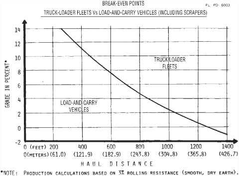
FIGURE 16.18 Load and carry, efficiency curve.
FIGURE 16.19 Load-haul-dump unit, large.
Operation is usually shuttle fashion, without turns. The machine self-loads at the digging face, rolls back the bucket, backs past a chute or hoist, and usually makes a small forward turning movement to dump into it. It then straightens out, and goes back to the heading.
Maximum speed is 15 miles per hour (24.2 kmph), but underground haulage roads usually demand slower movement. It has four-wheel drive with articulated construction, and can climb a 40 percent grade with a load.
Dumping height is the same as machine height, 6½ feet (2 m). An ejector bucket can dump a couple of feet higher.
The 911 LHD is the smallest in the line, with 4-foot (1.22-m) width and a height of only 44 inches (1.12 m). It may have either diesel or electric power, and can work in a tunnel as small as 6 × 6 feet (1.83 × 1.83 m). See Fig. 16.20.
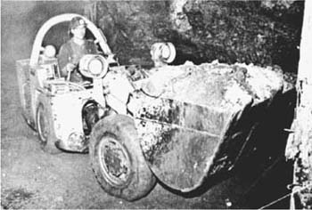
FIGURE 16.20 Load-haul-dump unit, small.
The floor of a truck body should be protected by a layer of dirt or other cushioning material, before placing big rocks on it. This is particularly important if they are to be dumped rather than lowered.
Loader buckets are not well adapted to picking up large, loose objects on the ground. They tend to push ahead of the edge unless it is dug into the ground under them, and the overhang of the back makes it hard to balance anything bulky on the floor.
Rollback buckets can pick up many objects by getting the edge under them, then tilting back the bucket until they fall in. Larger pieces, such as stumps or boulders, may be crowded against a steep bank which will prevent them from falling out while the bucket is rolled back enough that the object will slide in. Two loaders can lift the object between them until it settles into one of the buckets.
If the object is too large to be picked up in this way or there is nothing to crowd against, it can be maneuvered onto the floor and held from falling out by a chain to the top back of the bucket, as in Fig. 16.21. This method is especially effective with loose stumps resting upright.
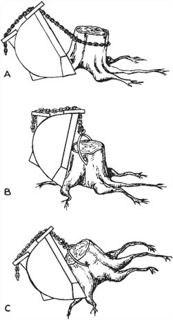
FIGURE 16.21 Picking up stumps.
A load usually settles back as it is raised or tilted back, so that it is easy to unhitch before dumping. If it settles forward and puts so much tension on the chain that it cannot be released, its overhang may be lowered so as to be supported by the truck sideboard or the pile. The chain may then be removed and the load boosted into position.
The bucket may also be lowered over a loose stump in dumped position, and attached by a chain or chain and tongs, as in (B). The bucket is curled, prying the stump up to a forward carrying position, as in (C).
For efficient odd-job use, or for crane work, it is almost essential to have a chain grab bracket, or a hook or hooks, fastened onto the top or back of the bucket. For use in dumped position, a second bracket on the rear beam is desirable.
A chain should not be anchored on a push arm and passed over the top of the bucket, as these change their relative positions during a lift, and the chain is likely to be stretched and broken.
A regular wide bulldozer blade may be substituted for the bucket. Its use is advisable if the machine is to be used as a pusher for scrapers, or if it is desired to equip it with grousers and do heavy digging in rocky soil. The blade is more rugged than the bucket. A wide blade enables the machine to turn in its path without climbing onto the edges of the cut. However, the standard width bucket will do most bulldozing jobs better than a bulldozer, and is immediately available for loading or other special work.
This blade is somewhat more effective than on a regular bulldozer, because the digging angle can be changed with the dump control to meet any change in the digging, and because the blade can be dumped at the top of steep piles, where part of the load has a tendency to ride back down the pile on a standard blade. In addition, it can be floated forward in full-dump position as well as backward to smooth over loose soil.
Bucket Manipulation. In dozer work, the bucket is used most efficiently by cutting with it in a digging position and spreading with it more or less dumped. In the latter position the bucket floor will have a tilt similar to that of a blade. Its advantages over a blade are the greatly increased cutting efficiency due to the knifelike edge; its ability to push bigger loads of soil because a good pushing load is contained in the bucket where it causes so little load or friction that nearly a full blade load can be pushed ahead of the bucket; faster grading work because of greater transporting capacity and ability to carry dirt to hollows without disturbing surfaces in between; the facility with which material can be backed out of banks; and the exactness with which it can be deposited where needed.
In backfilling against a wall, you may fill the bucket, put it in a flat position, and push a large amount of material ahead of it. Let this fall into the hole, then go back with the full bucket for more. This avoids the danger of hitting the wall with the upper part of the bucket.
Reach-down. A loader has greater effective reach below itself than any bulldozer. In the vertical position the bucket edge will reach more than 2 feet below the tracks, and it will cut a sheer wall to that depth. Because of their wide bases no dozer blades can be forced straight down or can reach such a depth in a short distance, even when capable of such a drop.
The ability to reach down enables the loader to cross sharp ridges without the bucket loader losing contact with the ground, a matter of great importance in clearing work. The bucket may also be used to ease the machine down lesser drops by holding it a foot or so above the bottom and walking very slowly off the edge. When the tractor overbalances, it will be supported by the bucket, which can be gradually hoisted, thus lowering the front of the tracks to the bottom. This process may crush the bank enough that the machine can then be walked off it, or it may be necessary to put small blocks to reduce the drop of the back.
Backdragging. The bucket is efficient at backdragging because the floor, when tilted straight down, can penetrate fairly hard material vertically, and because the clear space between the bucket and the tracks is sufficient to accommodate a lot of dirt. When backdragging in order to smooth loose dirt, the operator has a choice of tilting it to full dump, where it will cut through intermediate positions where it will not cut and will pull decreasing quantities of earth; to flat, where it will move hardly any. In the flat or near flat positions, down pressure can be applied so that loose dirt may be compacted.
General Considerations. But it can be seen that the operator usually needs two controls more or less continuously, versus one in a bulldozer, in order to bulldoze with a bucket. Some operators may dislike the machine for this reason.
Another drawback is that the location of the push arms between the tracks and the narrow path cut by the bucket enables stones and dirt to roll between the bucket and the track, making it necessary to lift the bucket and back far enough to get behind them in order to get through or to keep a grade. Also, the top of the bucket may be in the way of pushing close to a building.
A more serious consideration is the possibility of breaking up the bucket. It is not practical to make it as heavy or as strong as a bulldozer blade, and maintenance costs in heavy digging, particularly among rocks, may be higher. This is especially true if the operator does not keep the bucket at a proper angle when digging or if full grouser track shoes are used.
The use of the heavily built rock bucket for hard digging will materially reduce maintenance costs, but it necessitates the lifting of several hundred pounds of extra weight when loading.
The dumping rams may be used to push or pull the tractor when lack of traction or breakdown prevent it from walking in the regular way. The bucket is pushed down in firm ground or on a mat of poles or planks. Dumping the bucket will pull the tractor forward; closing it will push it back.
This control over the bucket edge can also be used in pulling stones back out of water or marsh, and in reducing the length of the machine to fit it in a short space.
In general bulldozing work where traction is good, a front-end-loader bucket should produce from 25 to 50 percent more work than a blade. It shows its greatest advantage in hard ground and among obstructions.
This special bucket has a back that is similar to a dozer blade, and a separate floor attached to upper hinges by the bucket sides. A pair of double-acting rams on the rear of the bucket can lift this clamshell fashion, or clamp it firmly against the bottom of the blade. It is equipped with a cutting edge at the base of the back, and another on the bucket lip.
Figure 16.22 shows some ways to use its special features. When the floor is raised all the way, the back of the bucket can be used as an ordinary dozer blade. If it is lifted slightly, it acts as a float or depth gauge to regulate depth of cut, and as a bowl for holding the cuttings.
If fully back, operation is the same as with a one-piece bucket. In addition it can be used clamshell fashion for picking up loose material without pushing it around.
It can also grip and raise substantial pieces, such as tree trunks and boulders. Such objects should be held at the center whenever possible, to avoid twisting the loader frame. Such clamped loads can be released only by opening the clam.
Loads lying in the bucket may be dumped through the bottom in this way, or by tilting the whole bucket forward, in the conventional way.
Bottom dump permits the loading of very high trucks, as the bucket lip does not swing down when discharging the load. However, it tends to fill only the near side.
FIGURE 16.22 Ways to use multipurpose bucket.
Ejector Bucket. A rock ejector bucket has a back wall that slides forward to completely clear the bucket of its load. Its movement is controlled by the tilt mechanism through a mechanical linkage. In any position less than full height, it advances automatically as the bucket floor is tilted downward.
At full height, however, the bucket floor stays level when the tilt lever is moved to DUMP, so that the back moves forward horizontally. Dumping is complete, and can be done at a greater height than is possible with a standard bucket, whose edge must pivot downward.
Side Loader. Side dump buckets as special equipment for regular front loaders were mentioned earlier. Such buckets are standard equipment on a number of small to medium-size crawler-mounted loaders designed for underground use. See Fig. 16.23.
In narrow tunnels, it is usually necessary for a mechanical loader to hoist the load overhead and dump it behind onto a belt or into a hauler.
A side loader can dig straight-on at the face, back alongside the dump point, and spill the load into it without turns. It then moves (trams) forward to refill.
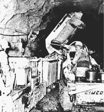
Dumping is faster than with an overhead, and less roof clearance is needed. All cars of a train (instead of just the nearest one) can be loaded without shuffling.
Side loaders are usually 4½ and 8½ tons (4,100 and 7,700 kg) in weight, with buckets from 15 to 35 cubic feet (0.42 to 1.0 cu.m) capacity. Width varies from 3 to 5 feet (0.9 to 1.5 m). Power is usually air or electric, but may be diesel.
The overshot mucker digs at the front in the same manner as a front-end loader. The filled bucket is then lifted entirely over the tractor, and dumped behind it. In spite of increasing competition from load-and-carry models, the overshot mucker is extensively used in mines and tunnels. See Fig. 16.24.
The bucket is mounted on a rocker frame that raises it as it is pulled back by a pair of leaf chains that wind on rear winch drums. After dumping, it returns to digging position by air or gravity.
The loader can be obtained in three different loading heights, and can be converted from one to another in the field. The high discharge can load trucks as high as 11 feet (3.4 m), and standard high railroad gondolas. It requires a headroom of 7 feet (2.1 m)—too high for many underground jobs. The low discharge will load a 7-foot (2.1-m) truck, and has a maximum height of only 12 feet (3.7 m).
The manufacturer of this kind of equipment also makes air and electric rocker shovels for use in tunnels and mines where space is more restricted. Model 21 runs on the same rails that carry the cars it loads. It can dig straight ahead, or swivel about 30° to either side. The loaded bucket is passed over the top of the machine and dumped into a car directly behind. The operator stands on a side platform. A great many models are made to suit particular requirements.
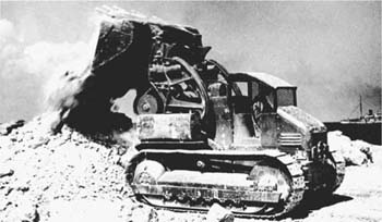
FIGURE 16.25 RockerShovel with conveyor.
The controls of Model 21 are shown in Fig. 16.25. The operator stands on the step plate and holds the two rubber-covered handles. Moving the left (front) one forward moves the machine forward; moving this same lever backward backs the machine. The rear curved lever can be moved forward to raise the bucket, backward to lower it, and to center (neutral) to lock it in any position.
The loading cycle is only 6 seconds, so this small machine can move a lot of muck in a shift.
Model 40H dumps its bucket onto a conveyor belt that carries the spoil well back from the machine. The front lever controls locomotion (crowd-retract) when moved forward and backward, and swings the bucket and deck when moved sideward. A small knee-operated lever controls the conveyor motor.