The belt conveyor is a transporting, elevating, or distributing machine made up of an endless wide belt which carries a load on its upper surface. It operates between a head and a tail pulley and is supported by idlers, which in turn are supported by a frame or by steel cables. Conveyors are made in small portable elevating units that are loaded with hand shovels, and as giants that carry millions of tons of earth for many miles.
As independent units, they are well suited for rapid transportation of loose material. They have less mobility and flexibility than trucks and scrapers, and are therefore used chiefly where large volumes of material are to be moved along one route. They are particularly applicable where the load must be lifted steeply, or carried across rough country where road construction would be difficult. They are desirable as feeders for processing plants because they provide an even and continuous flow. They simplify traffic problems where hauling space is restricted, as in tunnels and in busy pits. However, they are not adapted to hauling big chunks which clog hoppers, damage the belt, and are likely to fall off in transit.
Their mechanical efficiency is high, as very little deadweight must be moved with the load, friction is at a minimum, and power-consuming starts and stops are rare.
A conveyor can be kept in touch with a receding pit face by fitting in portable frame extensions and splicing in extra belt, by installing a feeder conveyor between the hopper and the face, or by trucking from the excavator to the belt.
In addition to their use as independent and semi-independent haulers, conveyor belts are used as parts of loading, ditching, and processing machines.
The large permanent type of belt conveyor is almost unique among machines used in connection with excavation in that it is usually custom-built and rules of design and construction are flexible, so that it can be “tailored” to the job.
In an average installation, the belt is about half of the original construction cost, and its repair and replacement are the biggest maintenance charge. Proper care of it is therefore very important.
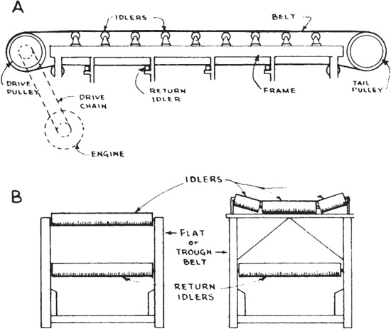
The belt extends between a head pulley (which may be the drive pulley) and a tail or return pulley, and carries its load on its upper surface, usually toward the head pulley. Its upper strand is supported by idler sets whose three rollers are arranged to shape it into a trough, and the lower strand is supported at wider intervals by flat rollers called return idlers.
Figure 14.1 shows the parts of a simple conveyor and Fig. 14.2 shows one in action. There is a frame which keeps the working parts in position, an engine that turns a drive pulley that moves the belt by friction, a tail pulley to reverse the direction of belt travel, and idlers and return idlers.
Frame. Many frames are of the sectional type. A head and a tail piece must always be used, and as many intermediate sections as are required to obtain the desired length. Sections are bolted to each other.
FIGURE 14.1 Belt conveyor parts.
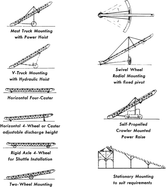
Figure 14.3 shows several ways of mounting rigid frames. Wheel and caster carriers are suitable only for light machines. Pillar and floor are usually permanent, but may be made so that they can be disassembled for moving. Stationary installations usually include a catwalk from which the belt and rollers can be serviced.
Conveyors may also be carried on two strands of wire rope with movable head and tail sections, on skids, and in other ways.
Belt. The belt is an endless flat strip of rubber-covered cotton or rayon fabric laid up in plies. Very long or heavily loaded belts may be reinforced with steel cable. The type of fabric, the number of plies, and any reinforcement which is present determine the strength of the belt. The rubber cover serves only to protect the fabric from abrasion and weather. Its thickness and quality are varied to suit different types of service. Several constructions are shown in Fig. 14.4.
There is no definite limit to the length of a single belt. More friction surface for the drive and stronger belt construction are needed as the unit is made longer, the climb steeper, or the load heavier. Common practice limits the carrying distance to ¼ mile (0.4 km), but belts with a carry of 1 mile (1.6 km) or more have been constructed.
Any distance can be crossed by a series of belts, each of which dumps on the next through a hopper or over a baffle plate. The length of each conveyor is figured between the centers of the head and tail pulleys.
FIGURE 14.2 Belt conveyor in action.
Belts which move dirt or any loose material are usually run with a trough in the upper surface, which centers the load and reduces spill off the sides. Very short conveyors may carry a bigger load by using a flat surface with fixed side skirts.
Belts may be from 8 inches (20 cm) to 8 feet (2.4 m) in width, but standard belts range from 12 inches (0.3 m) to 60 inches (1.5 m) with 30 inches (0.76 m) very common.
Drive. Power carries from the drive pulley to the belt by friction. If the resistance of the belt to moving is greater than the friction, the pulley will spin or slip inside the belt, with resultant loss of power, and will wear on both surfaces. The amount of friction or traction is determined by the nature of the surfaces, the slack side tension on the belt, and the area of contact.
The load or tension on the carrying strand of the belt, which tends to cause slippage, is made up of the pull of gravity on this strand and its load, friction in idlers, pulleys, the belt, and its load; and the inertia of the whole system when starting or accelerating.
The drive pulley surface may be bare metal, or covered by smooth face or grooved rubber lagging. Such lagging may be bolted or vulcanized in place. It increases traction, particularly when the belt is wet or frosty, and prevents pulley wear.
The belt is held in full contact with the pulley by its tension on the slack or low-tension side. This tension is normally regulated by some form of gravity takeup, in which a hanging weight exerts a pull on the tail pulley, or a special takeup pulley, which moves outward if the belt slackens and inward if it tightens. If the incline is steep, the weight of the slack side may maintain sufficient tension. Very short conveyors may have threaded adjustments to move the tail pulley in or out.
FIGURE 14.3 Conveyor mountings.
The amount of drive traction which may be obtained by increasing tension is limited by sharply increased power requirement and shortened life of a too-tight belt.
The area of contact is determined by pulley diameter, the arc of contact, and the number of pulleys. A thicker pulley not only increases the contact area, but also reduces flexing strain on the belt. Its disadvantage is the cost of the pulley itself and of changes in frame and layout to accommodate it.
If an existing drive pulley is replaced by a larger one, the belt will then be driven at higher speed with less power, unless the gearing or the motor is changed. Putting on lagging has the same effect.
FIGURE 14.4 Belt cross sections. (Courtesy of Hewitt-Robins Incorporated.)
A belt whose strands are parallel will have 180° of contact with the drive pulley. This contact can be increased by a snubbing pulley on the slack side. Increasing the degree of wrap in this manner is the cheapest way to increase contact area.
Head pulley drives are adequate for short conveyors, and for those so steeply inclined that the weight of the return strand maintains a high tension on the slack side. For conditions requiring greater traction, tandem pulleys are used; see lower right example in Fig. 14.5. Up to 440° of wrap can be obtained in this manner.
A belt which is pulling a load changes shape as it goes over a drive pulley. It is stretched thin where it first contacts it, and then fattens up as its tension is reduced. See Fig. 12.20. It moves fastest where it is thinnest, in the same manner that water is accelerated in going through a restricted place in its channel. The change in belt thickness and speed is quite small, but requires that the second of the tandem pulleys turn a bit more slowly than the first, if extra stress is to be avoided. The amount of difference varies with the load. Where electric drive is used, separate motors on the two pulleys can be made to automatically adjust their speeds to each other.
FIGURE 14.5 Drives and takeups. (Courtesy of Hewitt-Robins Incorporated.)
A possible disadvantage of tandem drive is that one pulley works on the load-carrying surface of the belt, which may be wet and slippery so as to afford a poor grip; or gritty so that excessive wear of both belt and pulley will occur. This may be avoided by using the head and lower pulley for drive, and the intermediate one as an idler.
A number of drive and takeup arrangements are shown in Fig. 14.5.
Short reversible belts may have drive pulleys at both ends, connected by roller chain.
Idlers. Idler rollers support the upper or working surface of the belt. They are usually of the troughing type, in which a horizontal center roll supports the loaded part of the belt, and a pair of outer rolls turn up the edges to create a trough cross section which keeps the load from spilling off the sides.
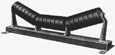
At loading points, shock and wear to both belt and idler can be reduced by using rubber idlers as in Fig. 14.6. The idlers turn on ball or roller bearings. Lubricant is usually renewed only at long intervals, and may be sealed in.
In excavation work, the flat idler and belt are used only on skirted conveyors.
Adjustment. Short belts commonly have a screw adjustment or takeup on the tail pulley, which slides in and out on a track. Care should be taken to adjust both sides equally to keep the axle at right angles to the direction of belt travel. Any cocking will make the belt tighter on one side than the other, so that it will tend to climb the pulley and run off the tight side.
FIGURE 14.6 Cushion idler. (Courtesy of Hewitt-Robins Incorporated.)
In long belts a fixed tension is not satisfactory, as the length of the frame is affected by changes in temperature, and the belt is affected by both temperature and moisture.
There are two common types of automatic takeup which keep the belt under constant tension. In the horizontal gravity or counterweight-and-rigging method, tension is controlled by a tail pulley in a track, which pulls it outward by means of a weight hanging from a pulley. With a vertical gravity takeup, a fixed tail pulley is used, and the weighted pulley hangs between two return idlers, preferably at or near the point of minimum belt tension. These constructions are indicated in Fig. 14.5.
If the belt stretches too far to be adjusted, a piece is cut out, the ends are stapled or vulcanized together, and the adjustments are reset.
Alignment. The belt is sensitive to tiny changes in frame and pulley alignment, which will cause it to wander out of a straight line. Internal changes in belt tension, or a splice which is beginning to pull apart, may have the same effect. Trouble with wandering can be greatly reduced by making both pulleys and frames wide enough that the belt does not have to run absolutely straight to keep out of trouble. The wider construction is more expensive, of course, but through the years it should more than pay for itself in longer belt life, and in reduced checking and adjusting.
If the framework is out of line, the carrying strand may still track well enough, being steered by the load seeking the idler troughs. The return strand, however, will find the shortest path, or allow itself to be influenced by sloping idlers, so that it will rub against stationary parts. Unfortunately, it is almost standard practice to carry the return strand inside the framework, where it is very difficult to see just what it is doing. It is much better to hang it below the frame members, where misbehavior can be readily observed and necessary corrections made before serious damage is done.
Troughed idlers will steer the belt if they are tipped in the direction it is moving. However, only a very slight tilt can be used, because if it is overdone, it will set up a drag against the bottom of the belt which will wear it rapidly and consume extra power.
Self-aligning or training idlers are mounted on a center swivel, and have vertical spools set at each edge. If the belt rubs against a spool, it tilts and presses a lined brake shoe against the adjoining roller, slowing it, swinging the idler, and shifting the belt back toward center. This device creates very little drag, and if placed every 50 feet (15.2 m) in place of regular idlers, will keep a belt in line under any ordinary conditions. Two placed at 30-foot (9.1-m) intervals ahead of the tail pulley will line the belt up properly to go under the loading point.
Holdbacks. An inclined conveyor tends to run backward when power is cut off, because the weight of the load pulls the upper part of the belt downhill. This tendency can be overcome by means of a brake of sufficient size, but it is often more convenient to use a device which will automatically lock it against turning backward, without interfering with normal movement of the belt.
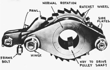
The holdback shown in Fig. 14.7 consists of a ratchet wheel keyed to the drive pulley shaft and held between a pair of side plates which are hinged to a toggle and tooth pawl anchored on the conveyor frame. When the belt and drive wheel are turning in the normal direction, friction between the ratchet and the side plates lifts the unit on the hinge, holding the pawl clear of the ratchet. If the drive wheel starts to turn backward, the hinge is pulled down and the pawl meshes with the ratchet.
FIGURE 14.7 Holdback. (Courtesy of Hewitt-Robins Incorporated.)
This device cannot be used on a conveyor transporting downhill, as its load tends to move the belt forward.
Hoppers and Loading. Hoppers are of two principal types: the primary or loading hopper, and the transfer. The primary usually has enough storage capacity that it can supply material steadily to the belt, although it is loaded intermittently by bucket or truck loads. See Fig. 14.8. It may have a screen or grizzly to keep out oversize pieces.

FIGURE 14.8 Loading hopper and conveyor. (Courtesy of Felco Industries, Ltd.)
Loading hoppers must have a restricted chute capacity, or a gate or feeding device to regulate the rate of delivery to the belt. In some installations, increased flow is obtained by merely raising the chute, so that more material can pass under its forward edge. For any rate of feed, the load per foot (meter) of belt will be increased by slowing the belt, and decreased by accelerating it. Regulating devices must be so constructed and used as to allow through the largest lumps which get into the body of the hopper, and to avoid jamming by several smaller lumps.
Various feeding devices are available to ensure even flow from the hopper to the belt. A short feeder conveyor (transition belt) may be used, either for convenience of location or to save the long belt the extra wear of taking a part in measuring out material. Another common device is a pan which moves back and forth under the hopper chute, carrying and pushing a fixed amount of material toward the belt with each move. Other models use shaking or vibrating plates, or rotating rolls or vanes.
A conveyor belt is loaded by a chute from a hopper or another conveyor, or by a feeding device. The material always has some vertical drop, and may be moving in a different direction and at a different speed than the belt. As a result, there is impact to the belt in stopping its fall and giving it its proper speed and direction. Chutes and baffles should be so constructed that they convert as much as possible of vertical and cross movement into movement in the direction of belt travel, and so that they deposit their load squarely in the center of the belt. If the material is abrasive, the chute may be so constructed that a layer of the material piles up on its slope and protects the belt. When the main conveyor is a big one, it may pay to put in a short feeder conveyor (transition belt) to ensure feed at the proper speed and in the right direction. This transfers wear from an expensive belt to an inexpensive one.
Coarse, lumpy materials, particularly when they include sharp edges, require greater precautions at the loading point than fine or soft ones do. Impact damage to the belt can be reduced by using thicker rubber on both the top and bottom surfaces, and by using closely spaced rubber-cushioned idlers at the loading point.
A certain amount of belt wear from impact and abrasion occurs each time the belt goes over an idler, as it is a high point with a sag on each side. The slight but steady wear at these points can be reduced by minimizing the sag, which is affected by belt tension and idler spacing. Maximum smoothing effect can be obtained from any given number of idlers by using wide spacing near the head, where tension is greatest, and progressively narrower spacing toward the tail pulley.
If the load slides back on itself while going up an incline, a lighter load may be more efficient. If it slides on the belt, a belt with a cleated surface may be required. Often a change in the moisture content of the earth will cause or cure this type of trouble.
Spillage. There is usually very little spillage off a belt which is wide enough for its load. However, many belts are overloaded in bulk if not in weight, and the jouncing over idlers, movements in the load, and changes in alignment result in pieces rolling and bouncing off the sides. If decking is placed under the full length of the belt, or sometimes under the ends and the loading point, this material will be kept from spilling onto the return belt. A clean belt and clean pulleys and idlers mean longer belt life.
It is important that a diagonal cleaner bar or plow be placed on the return strand just above the tail pulley, as a large sharp object might otherwise fall on the belt and catch between it and the pulley, so as to puncture the belt or even cut it into strips.
Wet dirt and many other materials stick to belts and will build up to considerable amounts if permitted to do so. A scraper may be placed just after the discharge point, to clean the belt and drop the scrapings into the same receptacle as the mainstream.
This cleaner may consist of a rubber or steel blade, or a series of them, or be a serrated rubber roll or bristle brush which revolves oppositely to the belt. See Figs. 14.9 and 14.10. Proper pressure against the belt and adjustment for wear are provided by counterweight or springs.
Troughs and Skirts. Most belts that carry loose material—and this includes excavated soil and blasted rock—are troughed so that the center is lower than the sides. The side idlers are usually at a slope of 20°. However, there is a trend toward steeper slopes, and 35° and 45° may now be used to increase load and/or reduce spillage.
FIGURE 14.9 Belt cleaner. (Courtesy of Hewitt-Robins Incorporated.)

FIGURE 14.10 Brush and rubber roll cleaners. (Courtesy of Hewitt-Robins Incorporated.)
Skirts are used to prevent spillage off the sides of a belt at a loading point, and to increase the capacity of short belts. They usually consist of vertical or sloped faces of metal or wood, with a lower piece of flexible rubber which makes light contact with the belt. This rubber should be lowered as it wears, and replaced whenever necessary, to avoid damage from material wedging under it. See Fig. 14.11.
Both troughs and skirts may be used at a loading point. The trough tends to keep material from reaching or pressing against the skirt and working under it. Trough slopes as steep as 50° may be used.
Trippers. A conveyor belt may discharge into any of several bins or piles. For a discharge point not at the end of the belt frame, a tripper may be used to dump the load into a sidecasting chute at any point. As shown in Fig. 14.12, it consists primarily of a pair of straight idler pulleys, one of which turns the belt under and dumps it, and the second returns it to its original direction.
The model illustrated is moved along tracks by a hand crank, and is anchored in position by a clamp. Other types can be propelled by the belt or by a separate motor, and can be under manual, automatic, or remote control.
Safety Devices. A belt conveyor will run for long periods without attention. Idlers require lubrication twice a year or less (if of the modern type with bearings and seals), a well-founded and constructed frame will keep the parts in line, and properly designed and protected chutes may never clog. However, sudden accidents happen, which can be very costly if their results are not controlled, and it is impossible to keep a worker always on the alert for events which may not happen for years, or ever. Controls should therefore be installed which will automatically react to emergencies.
If the power fails on an inclined belt, it will tend to run backward, jamming its load into and around the loading chute. This movement can be prevented by a holdback ratchet on the head or drive pulley, which will allow free working motion, but immediately lock against backsliding.

If objects jam between the belt and a pulley, if discharged material backs up into the belt, or if the belt runs off its rollers, the power requirement will be sharply increased. If drive is electric, an automatic overload switch in the line can be set to cut off the power, and prevent or limit the resulting damage.
It is also a good plan to use a motor which is not too big for its job. A 200-horsepower (149-kw) motor can drag a belt into a lot more trouble than a 100-horsepower (75-kw) can, without increasing current requirement as sharply. The oversize motor will also put greater stress on the belt when starting it with a load.
A moderate rise in power consumption without increase in load indicates increasing friction. It may be in dry or broken idlers, result from the belt rubbing the frame, or be caused by too much tension. A record of current consumption will often reveal such conditions before they would be observed otherwise.
Inclines. Conveyors are used for uphill, horizontal, and downhill (decline) transporting. See Fig. 14.13 for a bucket conveyor on a steep incline.
A belt will lift dry sand on an incline of about 15°, and wet sand up to 20°. Some cohesive materials can be carried on grades as steep as 28° on standard belts. The limiting factors are slippage between the belt and the load, and sliding of the load on itself.
FIGURE 14.13 Incline bucket conveyor.
Rough-surface belts may be used on somewhat steeper inclines if the load is thin. Belts with metal cleats will carry loads on inclines of up to 35° or 45°. Belts or chains with attached buckets can lift at any slope or vertically.
Capacities. Persons used to seeing dirt moved by the bucketful or truckload have difficulty appreciating the volume production represented by the thin ribbon of dirt on a belt.
Tables showing conveyor sizes, inclines, and recommended speed will be found in the Appendix. As one example, a 30-inch (0.76-m) belt carrying gravel weighing 3,400 pounds per yard (2,020 kg/cu.m), including occasional stones up to 14-inch (36 cm) diameter at 450 feet (137 m) per minute, will move about 520 yards (398 cu.m) per hour.
Output is usually figured in tons per hour, and conversion to yards made by means of average-weight data. Production is determined by the width of the belt, the speed of the belt, and the height to which it is piled. Power needs are proportioned to tonnage and lift.
Those variables make design of a conveyor system a complex matter, with plenty of room for difference of opinion. In general, increasing belt width means more expensive construction throughout. Increase of speed beyond specifications shortens belt life, and may involve lost power through slippage between the belt and the load. Heavier loading may call for stronger frame and idler construction, and heavier belting. In addition, a problem of spilling off the sides may be encountered.
If capacity of an existing installation is to be increased, the most economical, although often not the soundest, way is to increase power and speed and to maintain original load.
Recommended speeds for various materials range from 300 to 1,200 feet (91 to 366 m) per minute, with dirt, sand, and gravel in the higher rates.
FIGURE 14.14 Cross-country conveyor. (Courtesy of Hewitt-Robins Incorporated.)
Conveyors many miles (km) in length are often used in dam construction to bring material in from borrow pits. See Fig. 14.14. They can operate on grades much too steep for trucks, so that in rough country original construction may not be substantially more expensive than that of a haul road of equal capacity. Once built, a conveyor can show a much lower operating cost per yard than truck fleets.
Distribution of the fill may be handled by conveyors, trucks, or both.
Shiftable Frames. A conveyor used in an open pit may require frequent sideward moves to keep near a bank that is being cut back. Dismantling a conventional unit and setting it up again is likely to be costly in labor and in lost production.
A German construction technique is to mount the entire conveyor system on ties or skids that rest on a strip of land graded as if for a road. Idlers supports are grouped on frames about 15 feet (4.6 m) long that are not directly connected to each other. The frames are supported at each end by a pivot mounting on a cross tie or skid.
The ties are connected by one or two 90-pound (41-kg) railroad rails. A heavy four-wheel-drive tractor, equipped with a side boom, carries a roller clamp that holds the top of one of the rails. Shifting is done by lifting the clamp and rail slightly, and running the tractor parallel with the conveyor and at a slight distance from it. This will pull the rail and the whole conveyor 3 to 6 feet (0.9 to 1.8 m) to the side. A return trip in reverse moves it the same distance again. The process is repeated until the conveyor reaches its new location. The rail is flexible enough for the bending involved.
The head and tail sections are usually mounted on skids or pontoons, and held by tightening anchor lines by hand winches. Sideward movement involves towing with the tractor, or pushing with a dozer. Very large drive stations may have pontoons that are equipped with hydraulic-powered legs that can be used for tension adjustment and for side movement.
FIGURE 14.15 Extensible conveyor.
Extensible Conveyor. An extensible conveyor is a frame unit usually with mobile, crawler-mounted head and tail units. The head or drive unit holds up to 200 feet (61 m) of extra belt, moving back and forth over a series of takeup pulleys. The tail unit carries two reels of rope held by brakes.
In coal mining work, the tail unit may follow a continuous miner, as in Fig. 14.15, receiving its discharge directly or across a short loading bridge conveyor. It can also be loaded by shuttle cars or in any conventional manner.
During operation the tail unit travels as much as is necessary to keep in contact with the excavator, while the head unit is kept stationary at a point where it discharges into a main conveyor, haulers, or a processing plant.
Both the ropes and the belt pay out automatically as the distance between the head and tail is lengthened. It is only necessary to place extra idler frames to support the belt.
When the reserve belt has all been paid out into the working stretch, the conveyor is stopped and an extra piece of belt is spliced in. This should be long enough to cover the working distance and refill the storage rolls. The rope reels have sufficient capacity to take care of several belt extensions. A reserve belt 200 feet (61 m) long will permit a conveyor advance of 100 feet (30 m).
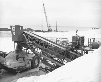
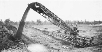
A conveyor may end in a pivoted boom to allow placing material in separate piles or to facilitate building piles or embankments to a desired shape or size. The machine shown in Fig. 14.16 is building a levee along the Mississippi River. The long conveyor in the background feeds it through a hopper. Such a conveyor might be loaded in a pit miles away, or by trucks at a nearby transfer point.
Stackers are usually custom-made. They can be stationary, towed, or self-propelled. Booms vary from 60 to 200 feet (18 to 61 m) in length, belt width from 24 to 54 inches (0.61 to 1.37 m), and capacity from 300 to over 1,000 tons (272,000 kg or over 900,000 kg) per hour.
They are frequently used in stacking of processed material in mine and factory yards. They also can load materials from a pit floor directly into trucks or trains on the high wall.
A belt loader may be any of a number of machines that load haulers or sidecast by means of a conveyor belt. The material may be pushed or dumped into a receiving hopper by other machines, or dug by a knife, blade, plowshare, disc, or bucket wheel that is part of the loader and is moved by it. In all these machines, the belt keeps the digging parts from being choked by accumulated cuttings, and is in itself the most economical type of elevator. As a result, these machines are a highly efficient type of loader under favorable circumstances, and are capable of very high volume of production in relation to power used. See Fig. 14.17.

FIGURE 14.17 Belt loader in action.
In general, they do best in materials of a fairly even texture that can be cut readily by their feeding devices. They are inconvenienced by stones and lumps that are large in proportion to belt width.
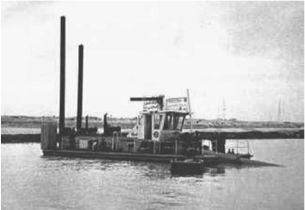
This type of belt loader does not propel or load itself, but can usually be moved around fairly readily. It consists of a heavy loading box or trap which is filled to the point of burial by bulldozers pushing material to it, a wide conveyor belt that carries the material to an elevated discharge point, an engine, and various accessories. See Fig. 14.18.
The trap must be very heavily built. Its opening may be either fixed or adjustable. If fixed, there is a reciprocating-plate feeder under it, to deliver more or less steady flow of material to the belt. If adjustable, it permits material to fall directly onto the belt, a desirable feature in sticky soil.
Box height, from base to the high end of the trap opening, may be 10 to 18 feet (3 to 5.5 m). The conveyor is comparatively short—40 to 60 feet (12 to 18 m)—and 4 to 6 feet (1.2 to 1.8 m) wide. Speed is moderate, about 350 feet (107 m) per minute.
The tail end is in the loading box. The discharge or head end is carried by a cantilever frame over the loading point. The head may be fitted with a vibrating grizzly or screen to carry oversize away from the hauler.
The belt and any accessory units are driven through chains and intermediate shafts by a diesel engine of 100 to over 200 horsepower (76.5 to over 149 kw).
The whole machine is a single unit, supplied with a detachable pneumatic-tire undercarriage, wheels, and a kingpin attachment for use with a fifth-wheel trailer hitch. In addition, the bottom of the trap is fitted with heavy skid plates, so that it can be dragged on the ground without damage.

FIGURE 14.18 Portable belt loader in action. (Courtesy of Athey Products Corporation.)
The discharge end ordinarily extends over a truck roadway. Discharge clearance may be 10 to 12 feet (3.05 to 3.66 m). The road may be excavated if more is required.
Since a standard machine has a fixed discharge position, a truck that has been loaded must move away before an empty one can be placed. Since the belt must be idle during the exchange, the reduced spotting time in drive-through is much more efficient than backing in.
Oversize. Loose rock in the bank may be in pieces that are too large for the trap, the belt, or the fill. In general, pieces that will go through the trap opening will be carried by the belt, so the first two situations are a single problem.
Fortunately, any rock big enough to cause difficulty is likely to be noticeable in front of the blade, before reaching the trap. Operators can be instructed to separate oversize pieces from the feed before they reach the trap.
The trap may be protected by welding on heavy grizzly bars, but rocks retained on them may be difficult to reach to get them out of the way.
For protection of fill quality, a belt loader may be equipped (preferably at the factory) with a shaking or vibrating screen at the conveyor discharge. This can separate oversize from acceptable material, with minimum operating cost.
With a screen, there should be two discharge points. The soil will fall through the screen close to the conveyor tip; the rejects will be carried farther, to the end of the screen. The two discharge streams must be sufficiently separated so that two trucks or other haulers can stand side by side, one under each discharge stream.
Haulers. A belt loader can discharge into any type of hauler that has an open top. This includes trucks and trailers of rear dump, bottom dump, and side dump construction; either highway or off-highway models (discussed in Chap.18); and nonelevator scrapers (discussed in Chap.17).
The principal consideration is that the haulers should be big, the bigger the better. Time for spotting a truck, figured from stopping the conveyor to restarting it, may average 15 seconds. A 60-inch (1.52-m) belt is rated at 1 cubic yard (0.76 cu.m) per second. Haulers carrying 45 yards (34.4 cu.m) (loose and heap) would keep the loader busy three-fourths of the time, ones with 15-yard (11.5-cu.m) capacity would work it only half the time.
Belt loading is kind to haulers, as the material is poured into them, instead of being dumped in big chunks from a bucket. With portable loaders, one loading spot is likely to be used for concentrated traffic for several days, so that it is likely to be well prepared and maintained. Scrapers are spared the heavy stresses of being pushed through a digging run.
Production. A 60-inch (1.5-m) belt loader is rated at 3,600 yards (2,750 cu.m) per hour. A loss of one-fourth or more due to hauler spotting may be assumed, reducing this to 2,700 yards (2,070 cu.m) per hour. Average production on a 45-minute per hour basis would be almost 2,000 yards (1,500 cu.m), which is a lot of dirt.
Loaders with 48-inch (1.2-m) belts are rated at 2,000 to 2,800 yards (1,500 to 2,100 cu.m) per hour, and 72-inch (1.8-m) units at 4,800 yards (3,700 cu.m). These figures are subject to the same markdowns for spotting time and 45-minute hours.
Wheel excavators have been widely used in other countries, particularly Germany, for many years, but have been uncommon in the United States until recently. Most of them are big, electric-powered machines designed for large-scale removal of soil overburden in strip and open-pit mines.
Booms. The wheel excavator has two conveyor-equipped booms. The digging boom or ladder carries the cutting wheel, and the discharge boom or stacker disposes of the cuttings. The two booms are mounted on a revolving superstructure. They may be fixed in line with each other, or may have partial swing independent of each other. In-line booms balance each other; independent ladders and long stackers must be equipped with counterweight structures. The two booms usually have separate hoists.
The ladder may be raised and lowered on a fixed pivot, or it may have a slide on which it can be crowded into the digging or pulled back from it.

FIGURE 14.19 Excavator and car loader.
Independent Loading Unit. Figure 14.19 shows a very large wheel excavator, digging a 100-foot (30-m) bank and discharging spoil across a bridge conveyor into a separate mobile loading unit with a two-train capacity. This machine can dig 100 feet (30 m) above its tracks and 16 feet (4.9 m) below. Its daily output is about 80,000 bank yards (61,000 cu.m). The excavator is mounted on three pairs of crawler tracks without leveling devices.
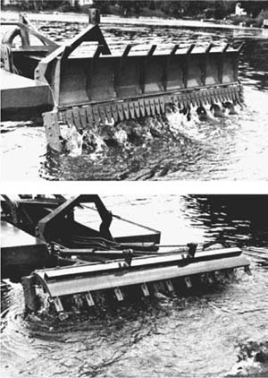
Elevating Graders. These machines dig with a plowshare or blade that cuts a slice of earth and slides it onto a conveyor belt, which elevates and dumps it. Models that are to be used for loading loose windrowed material may also have a set of chain-driven paddles to move the dirt onto the conveyor, as seen in Fig. 14.20.
The belt keeps the share from being choked with accumulated cuttings, and is in itself the most economical type of elevator. As a result, these machines are the most efficient type of loader under favorable circumstances, and are capable of a very high volume of production. They cannot be used in rock, and are severely inconvenienced by boulders.
The disc is adjusted to secure the desired depth, and width is regulated either by side shift or by steering the machine. Digging is done alongside the machine rather than under it. Height of bank and width of slice taken vary with the material. Generally, a slice 20 to 30 inches (0.51 to 0.76 m) high and 15 to 20 inches (0.38 to 0.51 m) wide is good procedure.
Low gear is standard for digging to obtain the power and stability for heavy cuts, and for easy synchronization of speed with trucks being loaded. However, second gear is often used when cuts are light and the spoil is sidecast.
A more complex adaptation enables a machine to make a quick, neat job of excavating a slot for road widening.
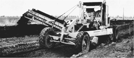
Force-Feed Loader. Athey’s force-feed loader, as pictured in Fig. 14.21, is a self-propelled, rubber-tire machine that is designed primarily for loading windrows of loose material including dirt, gravel, snow, leaves, and possibly broken pavement.
The plowshare wings rest on the ground and funnel loose material toward the center by action of the augers and the curved paddles as the loader moves into the material. The moldboard and feeder blades are raised together by a hydraulic ram and are lowered under control by gravity and hydraulic pressure. The discharge conveyor, which can have various angles from the centerline of the machine, is hydraulically driven, and its belt is controlled for variable speed.
Rear loading of trucks can permit the entire operation of digging and hauling to be in one lane. With the swiveling conveyor there is the option of loading or casting the material to either side of the loader. This machine can load up to 10 cubic yards (7.7 cu.m) per minute of loose material or as much as 20 cubic yards (15.3 cu.m) of snow per minute.
FIGURE 14.20 Elevating belt on grader.
The relative speeds of the loader and the feeder and conveyor depend on the transmission gear selected. The speed should be high enough to keep the feeder well filled without choking it. If a truck is being loaded, it must move at the right speed to keep the discharged material filling its bed. When the truck is filled, both the driving and digging clutches of the loader are released. The loaded truck drives away, and another truck is moved into position to be loaded.

FIGURE 14.21 Force-feed loader. (Courtesy of Athey Products Corporation.)
FIGURE 14.22 Hydraulic trencher loader. (Courtesy of Rivinius.)
Hydraulic Trencher Loader. The hydraulic trencher loader seen in Fig. 14.22 can be quickly attached to, or detached from, a prime mover for shoulder shaping, berm cleaning, windrow loading, borrow pit loading, or trenching. The rotary-spade, paddle blade feeders take rapid bites of material, which is moved up the feeder belt to a discharge cross conveyor, directed to the right or left for loading into trucks or into a windrow.
Continuous Miner. Coal, salt, potash, and other minerals are mined underground by machines that can cut them directly out of the solid vein, drop the material on a built-in chain conveyor, and load it into electric-powered, rubber-tire shuttle cars or continuous belt conveyors at the rear.
The Joy continuous mining machine in Fig. 14.23 has cutters mounted on sets of rotating wheels. It travels on reversible crawler treads. It is electric-powered and hydraulically controlled.
The cutting heads are swung by steering the whole machine, and in addition can be tilted and retracted by special controls. The discharge end of the conveyor can be swung to either side.
The crawler tread-gathering loader is designed to load coal that has been blasted from the seam. As the entire machine moves forward, the gathering arms on the loading head scoop up the coal and move it back to a built-in chain conveyor. See Fig. 14.24.
FIGURE 14.23 Two views of continuous miner.
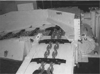
FIGURE 14.24 A chain conveyor.
The conveyor can be swung at an angle of 40° to either side to permit loading wide areas with minimum maneuvering. The machine is built in models for work in low, intermediate, or high seams.
Mucking Machines. When there is sufficient space, almost any excavator can be used for underground loading of blasted rock, minerals, or ore, known under the general term muck. However, there are a number of machines designed specially to work in small spaces, and to operate with air or electric power to minimize air pollution.
The Joy Loader, Fig. 14.25, is essentially a chain flight conveyor mounted on crawlers, equipped with a gathering head which is pushed into the base of the pile.
The Eimco Rocker Shovels have a front-mounted bucket that is loaded by pushing into the pile, and lifted over the machine to dump into a car coupled to the rear.
Small models are rail-mounted, and can swing the whole upper works to reach the sides. A conveyor belt can be added for longer reach.
Any of these loaders can be used in conjunction with portable conveyor belts, which discharge far enough to the rear that a whole train of cars can be run underneath the frame. When the front car is loaded, the locomotive moves ahead to put the next car under the discharge, until the last one. The loader and belt are then stopped, and the train pulls away. This setup is shown in Fig. 14.26.
In addition to their mucking work, loaders may be used as locomotives in switching cars at the heading, and in moving the jumbo and other equipment.

FIGURE 14.26 Use of portable conveyor in car loading.
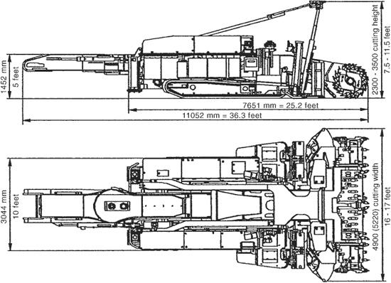
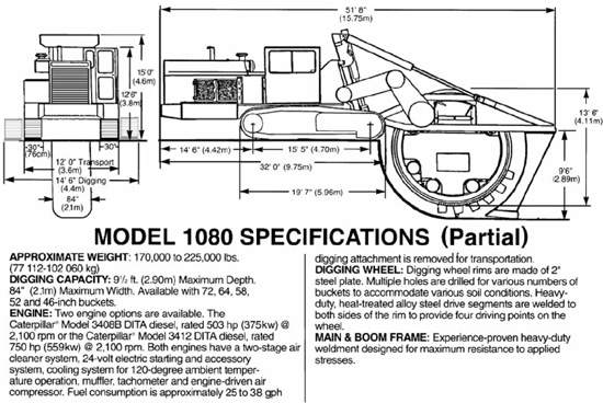
Construction. The Trencor model 1080, shown in Fig. 14.27, is representative of this class of machine. It consists of a crawler mounting, an engine on a front overhang frame, a cutting wheel, a conveyor belt, a shoe post, and the driving and control mechanisms.
The wheel, shown in greater detail in Fig. 14.28, is of channel construction with the buckets riveted or bolted to outside brackets. Both sides of the wheel are toothed and are driven by identical gears on the driveshaft (number one shaft). The wheel has no axle and is supported by idler wheels on an internal frame.
Various types of buckets are available. Solid-bottom buckets can be used in any soil that is not sticky, and must be used when the dirt is loose and powdery. The slat type is suitable for any soil cohesive enough not to fall between the bars.
Spring-loaded bars set on the frame at the dump point push the dirt out of slat buckets so that even the stickiest soils can be dug. Large stones in the bucket will force the bars back against the springs.
The conveyor belt carries dirt dumped by the buckets to either side and leaves it in a windrow. The belt is reversible and can be shifted sideward.
The shoe post and crumber is hinged at the top to the wheel frame and held in position by two turnbuckles. It serves to support the back of the wheel, pushes spillage ahead of it until it is picked up again, and rounds and smooths the bottom.
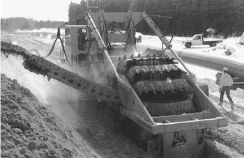
FIGURE 14.27 Large-wheel ditcher in action. (Courtesy of Trencor, Inc.)
FIGURE 14.28 Specifications for wheel ditcher. (Courtesy of Trencor, Inc.)
Power Units. The Trencor Jetco 1080 transmission is a three-element torque converter and constant-mesh planetary gearing with hydraulically applied clutches providing five forward speed ranges and one high-reduction reverse range. The crawler drive has a separate hydrostatic planetary speed reducer for each crawler driven by a two-speed hydraulic motor. This provides an infinite range of speeds to 1.4 miles (2.3 km) per hour. The wheel hoist is all hydraulic. The digging wheel drive is through a mast-mounted digging differential providing power to a unique radial arm drive.
Conveyor. The conveyor on a Trencor Jetco 1080 wheel ditcher is a high-volume, arc-type with hydrostatically powered end pulleys providing an infinite range of belt speeds to 1,000 feet (305 m) per minute in either direction. The 48-inch (1.22-m) -wide belt is hydraulically, transversely shiftable, with automatic antidrift brakes for precise placement of spoil.
Other Wheel Ditchers. A variety of wheel ditchers provide a range of digging depths from 4 to 10 feet (1.2 to 3m) with bucket speeds of 120 to 300 feet (36.6 to 91.4 m) per minute. Their ground travel speeds may vary from 2 (0.6m) to more than 100 feet (30.5 m) per minute.
Some wheels can be side-shifted, as shown in Fig. 14.29A, to work near obstructions, and/or tilted, as seen in Fig. 14.29B, to make vertical ditches on side slopes.
Operation. The buckets cut the earth and carry it forward to the top where they dump most of it on a conveyor which carries it to the side and piles it.
In starting a cut, as the wheel is lowered to the ground, the buckets will start to dig. The machine is stationary. Enough weight should be allowed to rest on the buckets that they will fill heaping without gouging deeply enough to slow the wheel.
FIGURE 14.29A Side-to-side shift.

If no shoe is used, the wheel can be lowered to cut bottom grade before walking the machine. The ditch will have a rounded start, as in Fig. 14.30(A). Position should be such that the center of the wheel is over the starting point of the full-depth ditch.
If a shoe is used, the rear hoist is pulled high and the wheel lowered in the position shown in (B). When the buckets cut so far that the shoe rests on the ground, the ditcher is moved forward. The rear supports are held so that the rear weight rests on the shoe and only enough force is kept on the front support to prevent the buckets from biting too hard.
The wheel will cut to an increasing depth as the supporting shoe is pulled into the ditch, and the front hydraulic lift allows the wheel to sink.
When bottom grade or the limit of depth of cut is almost reached, the wheel is held from further down-cutting by holding the front supports, while continuing motion. The shoe will move down the ramp until it levels out. The rest of the cutting at that depth is done with rear support held and front hydraulic cylinder tight, unless it is the full depth to which the machine will dig, in which case both supports can be slack.
Control of the machine is complicated by the fact that the digging center is behind the tilting and turning center of the tractor. If the tractor starts up a grade or over a bump, a shoeless wheel will dig down and will have to be raised to keep level. If supported by a shoe, it will not cut down and may be raised slightly.
In starting down a grade, the tractor will pitch forward. The wheel will tend to rise out of the ground, and either the front or rear support should be relaxed to drop it to grade. If a shoe is used, a slight pitch might not require any attention, as the back will lower itself on its support. Greater pitch would involve dropping the wheel slightly with the front hoist with extra relaxing of the rear supports.
FIGURE 14.30 Starting wheel cut.
Digging. When the wheel is at the correct depth, the machine is moved forward just fast enough to keep the buckets reasonably full. Crowding too hard will overwork the engine and put a heavy strain on the digging parts without adding particularly to the output. If there is a safety clutch on the digging mechanism, it may slip excessively and heat under overload.
Selection of the right speed range for various types of digging must be based on experience. If either the machine or the soil conditions are unfamiliar, it is good policy to err on the side of underfilling rather than overcrowding.
Soft rock usually responds best to a high wheel speed with a very slow walking speed. If dirt is very soft, it can sometimes be crowded so that material in excess of the bucket capacity piles on each side of the ditch without damage.
Obstructions. Where boulders, heavy roots, or pipelines are liable to be met, both walking and wheel speeds should be low and the engine should be throttled down at critical points.
Soft boulders will be cut through by the teeth. Hard ones may be pulled up to the surface. This is less likely to happen if the boulder is deeply buried, because the deeper boulder not only is held down by a greater weight of dirt, but the direction of the tooth contact tends to force it forward rather than up.
The wheel will usually ride over a deep stone it cannot move, so that it will be lifted above grade. If a big stone is near the top, it may stop the forward motion of the machine, in which case power should be cut off promptly.
If a boulder is pulled to the surface, it is liable to land in a very inconvenient spot, forward of the wheel and between the tracks. It may be necessary to lift the wheel into transporting position, walk forward until clear of the rock, push it out of the way, and back up until the wheel can be lowered to the ditch bottom. If the boulder is too large for the wheel to clear, the wheel drive clutch may be released so that the wheel can turn as it crosses it.
It is sometimes easier to cut and repair tile lines than to work over them. Where they are expected, tile of proper sizes and joint fillers should be kept on the job.
Turning. Turning must be done with great caution while digging, as the whole machine revolves around the center of one track, which causes the wheel to move sideward in the earth. If the buckets are equipped with long side teeth, or side cutting bars are used, and the earth is reasonably soft, a gradual turn can be made without damage. However, too sharp a turn may bend the wheel frame or the wheel itself, or pull the wheel frame off the vertical track.
If a shoe is used, it further limits the ability to follow a curve, and if very long, such as a tile-laying shoe, may prevent any significant turning unless it is loose enough, or hinged, so that it can trail instead of being swung wide.
Line and Grade. In most ditching work, it is important to keep the machine both accurately in line and working at the proper depth, although the operator cannot see the bottom.
The ditch is first surveyed, and the course and the depth of cut are ascertained. A line is then established at a fixed and constant distance above the bottom grade, and offset from the center beyond the track line of the ditcher. This can be done with a laser set up as described in Chap. 2 and seen in Fig. 14.31.
A rigid bar is fastened to the front of the power unit of the ditcher, with one end over the string when the ditching wheel is centered on the ditch line. A plumb bob or other weight is fastened to the bar so that it will hang directly over the string. If a laser system is used, a target is mounted on the machine, as seen in Fig. 14.32.
The operator can then keep the machine on correct line by keeping the plumb bob just over the string or the laser beam on the target. If the ground is irregular, the cord holding the plumb bob can be run through eyes or pulleys so that the operator can reach an end of it to raise and lower it when necessary.
The same apparatus fastened on the side beam of the wheel can be used with a fixed length of string to determine both line and depth.
Trapezoidal Ditchers. Permanent irrigation ditches usually have a flat bottom and sloped sides. A wheel ditcher may be fitted with side cutters, called cones, that enable the wheel to produce this shape in one pass.
Two types of cones are used. One is driven directly by the wheel through its axle. These cannot be adjusted for different slopes, but they can be set out with spacers for a wider ditch. See Fig. 14.32.
FIGURE 14.31 Chain trencher with laser guidance. (Courtesy of Trencor, Inc.)

FIGURE 14.32 Trapezoidal ditcher. (Courtesy of Trencor, Inc.)
The others are turned by hydraulic motors. Their vertical angle can be increased or decreased by adjusting support rod length.
Both types move the cuttings down the slope to the wheel buckets, which carry them to the conveyor for discharge to the side.
In soft, caving soil, cones may be replaced by sloper bars, which are rigid blades held in side frames. They slice the dirt, which falls down to the buckets. The bars are simpler and cheaper, but are too hard to pull in many soils.
The class of ditchers which pulls by a chain or cutter blades and drags the cuttings to the surface, rather than lifting them in buckets, may conveniently be called chain or drag trenchers. (See Figs. 14.33 and 14.34.) Many are small, 3 tons (2700 kg), but the chain trencher can be very large, as seen in Fig. 14.31. Some carry other related equipment such as a cable-laying plow, a cable reel, or a backfill blade and/or a backhoe on the other end of the tractor.
Depending on size and arrangements, the operator may stand beside the trencher and steer it with handlebars, sit on it sidesaddle, or have a regular tractor-style seat and control station.
In the digging, the machine should be propelled forward fast enough to keep the cutters loaded with soil, but not so fast as to slow or stall them. Since the resistance of soil may change frequently, it is necessary to keep alert and be ready to make adjustments often.
Usually the cutters are run at a uniform rate, and the ground speed is adjusted as necessary. This is particularly the case with machines having hydrostatic drive to the wheels.
When the cutters are moving rapidly, they throw cuttings out of the trench with considerable force. Most of the pieces strike baffles and fall harmlessly to the sides, but they can be a nuisance and a danger to a person close to the discharge point.

FIGURE 14.33 Chain trencher in action. (Courtesy of Vermeer Manufacturing Company.)
FIGURE 14.34 Drag trenching. (Courtesy of Vermeer Manufacturing Company.)
They are usually moved back from the edge by rotation of a pair of auger flights, to prevent sliding back into the slot. Cutters are usually carried on a roller chain. For cutting slots in rock or pavement, however, a solid wheel with carbide teeth may be used. Over crowding can be very expensive with these, as it can cause breakage of a number of teeth in one turn of the wheel.
Cable or small, conduit-laying plows are discussed in Chap. 21.
Hydraulic dredges consist of floating pumps, which suck in mixtures of soil and water and deliver them to a disposal point through a pipeline. They can excavate underwater soil or waterside banks, transport spoil through pipes, and rough-grade it on the fills. A single machine, with proper accessories, may perform all three functions, or it may dig without transporting, or a dredge-type pump may transport from a hog box without digging the soil itself.
General Construction. The heart of the hydraulic dredge is the main centrifugal pump with its suction and discharge lines. Except for hog box work, the pump, power plant, and accessories are mounted in a floating hull. The suction line is carried in a live boom called the ladder. Its position and the working movements of the hull are controlled by winches and spuds on the hull, and by anchors on the bottom or on shore.
Plain suction dredges, such as the Ellicott machine shown in Fig. 14.35, erode the bank by the force of water flowing into the suction head.
High-pressure jets of water may be set around the rim of the head to loosen the soil. These are suitable for dredging loose, free-flowing material such as sand and some gravel deposits. They should not be used where there are many pieces too large to go through the pump, or where the bottom must be cut to a definite grade.
FIGURE 14.35 Hydraulic dredge in action. (Courtesy of Ellicott Machine Corporation.)
As a rule, suction dredges are moved around the job by winch lines to bottom or shore anchors, and they dig a succession of overlapping pits.
Cutter dredges, shown in Fig. 14.36, loosen material by means of revolving blades or chains. Position control is through two spuds on which the machine pivots, and a pair of swing anchors. While digging, the cutter is kept in almost continuous horizontal motion back and forth through an arc.
Dredges are usually rated as to size by the diameter of the pump discharge line, which is usually smaller than the suction pipe. Range is 6 to 30 inches.
Hull. The standard hull shape is rectangular, but the bow (front) may be tapered for work in narrow channels. The ladder is hinged at the deck edge, or set back into a slot or well for better stability.
Modern practice is to make hulls of steel divided into compartments. The steel is desirable to withstand the severe vibration of the dredging. The compartments prevent sinking from a single leak, and make it possible to trim (level) the dredge by selective pumping or filling.
The barge may be made of a number of pontoons bolted together. This construction is used when it is likely to be necessary to dismantle it for moves between jobs, or when it must be shipped overland to its first job.
The main machinery should be mounted in a single pontoon or section when possible, to avoid delay and damage during taking apart and reassembling.
Hull size is determined first by the weight of machinery to be floated, and second by the need to support and counterbalance the overhang of the ladder.
Cross section is varied according to special requirements. Dredging shallow channels requires little draft, so that length and width must be increased to provide support at the surface. Narrow channels call for reduced width with greater depth or length.
Large dredges may contain hoppers for storage of spoil, and may be equipped with screening, crushing, and washing plants for processing it.
Seagoing dredges are often of the hopper type, and may have a tapered hull propelled by their own engines. Other dredges are towed from job to job, or taken apart and shipped.
Power Plants. Power may be diesel or electric. The dredge in Fig. 14.36 has two diesel engines. One drives the pump, the other turns the main generator that supplies current to run the cutter, winches, and accessories. Two engines are used so that the pump can work steadily at full capacity, without being affected by the variable requirements of the other equipment.
All-electric drive is frequently used in dredges that work within reach of power lines. They may also be used with a shore generating set. Current is brought from shore by special submarine cable, or supported on the discharge pipe floats.
Electric power makes a cleaner and quieter dredge and eliminates the fueling problem. However, caring for the power lines may be difficult because of danger from high voltage, movements of the dredge, and change in length of the discharge line.
Pumps. The main or suction pump is of the centrifugal type, with wide clearances which permit pumping a high proportion of solids and passing of large pieces. Construction is varied according to the depth of digging, the length and rise of the discharge line, and the coarseness or abrasive qualities of the spoil. The pump must be able to maintain a suction velocity of at least 12 feet (3.7 m) per second.
These units are designed so that most of the wear is taken by replaceable liners or tips. White iron, and manganese and nickel alloys are extensively used for these parts. Shafting is extraheavy to minimize shock damage from jamming on stones or logs.
Because of the clearances required, efficiency is usually only about 50 to 65 percent, and that is in a rather narrow speed range. If the engine has a different speed, pulleys or gears must be used to adapt it. Belt drives are often used because of their shock-absorbing nature. Power requirement is greatest when pumping heavy volume against a low head.
The pump may be mounted partly or wholly below outside water level, so that it will prime by gravity. If it will not, a valve may be closed in the discharge line and air pulled out by means of a vacuum pump or exhaust blower. Other units prime by raising the suction line and filling it by means of an auxiliary pump.
The auxiliary pump, usually a centrifugal, is used for wetting stuffing boxes and water-lubricated bearings, priming, flushing decks, and miscellaneous jobs. If a high-pressure type, it can supply water for jetting deposits around a plain suction line.
Suction Boom. A plain suction dredge boom may consist of a pipe, supported by cables attached to a jack boom, which is raised and lowered by a winch line. Rubber hose of special construction is used at the upper end where it meets the hull, and heavy metal pipe for the balance. A suction hood is flared out and equipped with guards to keep out oversize rock. If agitation is used, the opening is smaller and the high-pressure jets are arranged around its rim. The pressure water line is fastened to the outside of the suction line.

FIGURE 14.36 Cutter dredges. (Courtesy of Ellicott Machine Corporation.)
A lattice boom or ladder may also be used to support the pipes.
Ladder. A cutter must be supported by a ladder boom strong enough to carry its weight, withstand side stresses, and keep the driveshaft in alignment. The jack boom is fixed, and a multiple-winch line runs from it to the ladder point. The swinging lines are run from winches around swing sheaves near the cutter end, and outward to side anchors.
The open end of the suction line is carried in the suction head on the cutter end. This head contains the end bushing for the driveshaft and the supporting flange for the cutter.
Digging Depth. The downward angle of the ladder during digging varies from a few degrees to a standard maximum of 45°. The greatest depth to which a dredge will dig is therefore about seven-tenths of the length of the ladder. Large machines ordinarily carry longer ladders than small ones.
Increasing the digging depth of a dredge adds greatly to its cost. The longer ladder demands additional buoyancy at the front to support it and weight at the back to counterbalance it, which means a substantial increase in the size and weight of the hull. The pump may also need redesign and additional power to develop the extra suction needed.
A dredge with an oversize ladder, hull, and pump engine with a special pump will have only about the output of a standard dredge of the same size, but the cost might be greater than that of a larger dredge with standard digging depth.
Under very special conditions, ladder angles up to 60° are sometimes used for increased depth.
Plain suction lines or ladders are much lighter and can be extended downward at less cost. A cutter machine, under necessity of digging a loose deposit below its reach, may have the cutter head removed and an extension suction pipe installed.
Depth of cut can sometimes be increased by partially draining the water body in which the dredge works or by diverting the waste water away from it, so that the digging will serve to pump out water and lower its surface level.
Forty feet is the deepest cut ordinarily recommended, but with special constructions and under favorable conditions depths down to 100 feet (30 m) below water surface have been excavated. Fifty feet (15.4 m) usually makes an adequate channel for oceangoing vessels.
Cutter Heads. The cutter head is driven through a shaft from a power plant mounted on the deck or on the upper part of the ladder. The lower end of the shaft is supported in a long bushing which is lubricated and flushed by clean water supplied by the auxiliary pump. The shaft may be fitted with a weak section that is easy to replace, or with a shear pin, for protection of the machinery if the cutter jams.
Cutter drives are occasionally reversible to aid in cleaning off vegetation caught in the blades.
The cutter head is fastened by a key and nut and is sometimes steadied by a backing flange. It encloses the suction head and serves to slice, chop, and stir up material so that it is easily picked up by the water flowing between the blades into the pipe.
There are several types of cutter heads. Each is made in a variety of sizes, and many in several weight classes as well. One-piece construction is the cheapest, but when worn, will have to be built up by welding, or scrapped.
Others use detachable blades or renewable blade edges. Teeth can be welded on the blades or sockets welded to carry renewable teeth. The proper number, shape, and protection of blades for various types of digging will have an important effect on dredge output and cutter life.
Large dredges with toothed cutters can dig cemented gravel, hard clay, and soft rock.
When in doubt about the proper cutter head, it is usually best to take a heavy type, as reduction in maintenance and downtime usually more than offsets the higher price.
In hard, abrasive digging it is good practice to keep a complete spare cutter head, as replacing wearing parts may take considerable time, particularly if the head has been sprung or damaged by rough usage.
Winches. Plain suction dredges require a power winch to raise and lower the suction line and two to four power or hand winches for anchor lines and miscellaneous lifting.
FIGURE 14.37 Spud wells—and dredge factory. (Courtesy of Ellicott Machine Corporation.)
Cutter dredges need at least five drums under individual clutch and brake control. Two control the swinging of the dredge, one the raising and lowering of the ladder, and two the spuds. Additional power or hand winches may be provided for handling barges, shore lines, and materials.
Control levers may be at the winch, as shown, or grouped in a pilot house. Mechanical, hydraulic, or air controls are used.
Spuds. The spud wells, Fig. 14.37, are two pairs of guide collars mounted on the rear, stern, or spud end of the dredge hull. They are of two-piece construction so that they can be opened for convenient installation of the spuds. They are heavily made and securely fastened to reinforcements on the hull, as they have to withstand the reaction from the swinging of the dredge.
The spuds, Fig. 14.38, are heavy steel tubes, pointed at one end and provided with a lifting band and sheave block at the other. Hoist lines from the winch pass over sheaves in the spud gantry, around the spud sheaves, and are anchored on the tower.
Spuds must be long enough to reach the bottom without passing through the upper spud well. They are used to hold the dredge against digging resistance, wind, and tide and to advance it while working.
One, called the working spud, usually nearest to the discharge line, is down during digging, and provides stability against thrust and a pivot on which the dredge swings. The other, the walking spud, is used as a pivot in moving the dredge.
FIGURE 14.38 Spuds and shop carrier. (Courtesy of Ellicott Machine Corporation.)
Canal Dredge. Figure 14.39 shows a dredge made specially for construction and maintenance of narrow, shallow canals where spoil can be jetted over a bank or pumped through a short discharge line.
During digging this dredge is held in position by four spuds. The ladder and cutter move independently of the hull. Swing, hoist, and down pressure are hydraulic.
Advancing into the cut requires raising the front spuds, and rocking the rear ones alternately with a walking motion.
Sizes range from 6 to 12 inches (15.2 to 30.5 cm), cutting widths in single passes are 12 to 20 feet (3.7 to 6.1 m), and maximum depth varies from 8 to 12 feet (2.4 to 3.7 m).
Bumboats and Anchors. When working in narrow channels, dredges may be manipulated by lines to objects on shore or to anchors dropped in dug holes. Access to the shore may be by the discharge pipe, catwalks, or a rowboat. Floating pipe may be handled by a shore crane.
Under most working conditions, however, a small barge or boat with a hoist adequate to handle anchors and pipes, and an engine to move it around, is required. Sometimes the hoist will be on a barge which is moved by a small motorboat, but it is more efficient to combine the two.
A heavily made boat on the style of a large flat-bottom rowboat with an outboard motor for propulsion and a hand winch for the hoist will be adequate for small and many medium dredges. Larger units may require a working deck, inboard power plant, and a power winch.
Anchors are usually of the fluke type, weighing 300 to 400 pounds (136 to 182 kg) for small dredges. When used for swinging, they are placed beside the ladder, and well off to each side, making certain the cutters will not foul their lines at the ends of the swing. When the dredge has moved forward so that the lines pitch back too much for efficiency, they are picked up and moved forward. If the dredge path is curved, the outside anchor is advanced farthest.

FIGURE 14.39 Canal dredge. (Courtesy of Ellicott Machine Corporation.)
FIGURE 14.40 Float and discharge line section.
Floating Discharge Line. If discharge is into a barge or hopper, a very short pipe with an open flap valve is used.
If the spoil is to be used as fill, heavy pipe takes it to the rear (spud end or stern) of the dredge. A lighter pipe on floats carries it to land where a still lighter shore pipe takes it to the discharge point.
Floating pipe is made of high carbon or alloy steel, generally in 20- to 40-foot (6.1- to 12.2-m) lengths that have raised rims at the ends. Pieces are connected by short pieces of rubber hose with screw clamps. This arrangement provides flexibility to allow for motion from wind, waves, and advancing of the dredge, combined with great resistance to pulling apart.
Floats may be composed of oil drums with a metal or steel frame, of steel tanks as in Fig. 14.40, or small wooden barges. Each float normally carries one pipe section. An A-frame or cherry picker hoist with a hand winch may be built into the float nearest to shore to partly support that pipe so as to reduce the vertical angle with the shore pipe. Another hoist may be kept at the point behind the dredge where the line is opened to install extra sections.
The floats may have a light hand railing for use in walking along the pipe. Telephone and electric cables may be carried beside the pipe, or wires on short poles above the rail.
The pipe wears fastest on the bottom, and its life can be prolonged by rotating the straight pieces one-third of a turn occasionally.
“Floating” pipe is sometimes laid on the bottom, underwater, to leave a channel open for shipping.
Shore Lines. Fixed shore lines leading to a permanent discharge point such as a gravel plant are customarily made of heavy pipe with bolted or threaded flanges.
Shore pipe of the standard movable type is of light welded construction, with one end expanded and the other tapered so that adjoining pieces make a sliding fit. Metal is high carbon or alloy steel, 10 to 16 gauge.
Each end carries a pair of shallow hooks to permit fastening the connection with wire or weaving wire rope along a number of sections.
The tapered joints are somewhat flexible so that the pipe can be laid and used slightly out of line. This causes additional back pressure and wear, but is often unavoidable near the discharge end.
The stream may be allowed to spurt directly out of the last pipe, or may be broken up and spread out by various types of baffles or Y or T ends which reduce pitting and make a wider fill.
Window valves are adjustable openings in the bottom of sections of pipe. They are used to distribute fill along the line of a pipe instead of concentrating it at the end, in order to produce a smoother grade.
Shore pipe ordinarily lies on the ground or fill surface, but is carried on a trestle of some sort if window valves are used, if a deep fill is to be made from a single discharge point, or if the discharge point is changed by removing pipe sections rather than adding them.
Y-shaped diversion valves operated by a hand crank are used to change the flow from one branch pipe to another.
Output. The output of a dredge, Fig. 14.41, table A, depends on the capacity of the pump, the depth of digging, the height of discharge, the line friction, and the percentage of solids. Pump capacity is expressed in terms of yards per hour of solids. Ability to maintain production against a high head requires increase in power over that needed for a low head.
FIGURE 14.41 Dredge output tables. (Courtesy of Ellicott Machine Corporation.)
The vacuum required to raise the load depends on depth and percentage of solids. Aside from friction, it must be able to lift the excess of weight in the suction pipe over the weight of the same volume of plain water, which is the underwater weight of the solids.
The height of discharge and the friction head combine to produce back pressure on the pump. Pumps may be designed to work against either high or low heads.
Recommended maximum lengths of discharge line for nominal heights are given in table B. Much longer lines may be used, but with diminishing output or increased power requirement.
If the required line length of lift is beyond the capacity of the dredge pump, a booster pump of the same characteristics should be installed in the discharge line.
The most critical factor in output of any particular dredge is the proportion of solids carried. Except under conditions of overload, there is little difference in volume or cost between pumping low and high percentages of solids. Dredge output is usually calculated on a basis of 10 percent, but if 20 percent solids can be carried, production is doubled.
Proportion of solids can be increased first by the proper use of the correct type of cutter, and second by increasing velocity of flow by the elimination of sharp bends, reducing the size of the discharge pipe, or speeding up the pump.
The limit on percentage of solids is the plugging point of the pipe. This will be reached more quickly at low velocities, and with smaller loads of coarse material such as gravel, than with fine soil such as silt, or light stuff such as humus. Plugs are expensive to remove and must be avoided.
Advancing. The dredge is advanced into the digging by the pull of the swing winches and the pivot action of the spuds. One of these, called the working spud, is down while the dredge digs; the other is used for advancing. The swing lines go around sheaves near the end of the suction ladder to anchors placed at each side.
The movements are made with the pump operating and the cutter head revolving. Firm material is taken in slices from the top down by lowering the ladder at the end of the swing. Flowing or sliding soil may be dug at the toe only.
When the material within reach of the cutter has been dug to bottom grade, the ladder is lifted until the cutter is above the top of the bank and the dredge swung to starboard. The walking spud is dropped, the working spud raised, and the dredge pulled to the left. This causes the dredge to pivot on the walking spud, moving the working spud forward a distance determined by the extent of the side swing.
The working spud is then dropped, the walking spud raised, and digging resumed.
Spuds must penetrate the bottom sufficiently for a firm grip. If the bottom is hard, extraheavy spuds may be required, and it may be necessary to raise and drop one of them several times in one place in order to sink it.
Anchors must be raised and moved forward occasionally to avoid backpull from the swing lines.
Cutting. The standard dredge does its hard digging while swinging toward starboard, with the cutter blades slicing up into the bank. The swing back to port is usually made with the cutter at the same level, cleaning up loosened material.
The revolving of the cutter causes it to act as a driving wheel, pushing the ladder to the left. This push will be weak in loose sand and strong in hard formations. On the right swing, the winch must overcome this resistance in addition to crowding the blades into the digging.
When swinging to the left, the cutter may pull the ladder too rapidly for effective cleaning and cause the winch line to run slack, and foul on the cutter. In this case the right-hand winch brake is applied enough to hold the cutter back to line speed.
Dry banks are undermined by cutting below the water level so that they slide or cave into the water where they can be picked up by the suction. The height that can be safely reduced this way depends on how readily it slides and the size of the unit. If too much material comes down at one time, it may bury the ladder or damage the dredge.
It is usual for a dredge to cut to bottom grade at each stand, regardless of the depth of material to be moved. Moving the dredge, with the attendant work of shifting anchors and extending discharge lines, is laborious.
The percentage of solids moved is regulated by the size of the slice taken with each pass and the speed with which it is cut. The slice can be enlarged by advancing the dredge farther toward the bank or by lowering the ladder. Cutting speed depends primarily on the hardness of the material and is controlled by the speed of the swing line, which can be reduced from maximum by throttling the engine, shifting to a lower gear, or slipping or intermittently disengaging the clutch. If the winch cannot pull at full speed, production may be increased by turning the cutter faster.
The dirt cut or stirred up by the blades falls inside the cutter head or is carried around the outside. Water pulled in from the top and the left side by suction of the pump further breaks up the pieces and carries them up the suction pump.
A skillful operator will keep the intake of solids as high as their nature and the velocity of the discharge line permit without plugging. But the operator should not allow the line to plug, as cleaning it out is liable to be a long and tedious job involving downtime that will far outweigh the gain of extra few percent of solids that caused it. A blocked line is particularly serious in freezing weather.
A dredge is generally run on a two- or three-shift basis, because of its high original cost, and a desire to spread its overhead over as many work hours as possible. It will often be run through lunch periods by a split crew.
Clearing. Vegetation should be cleared away from the path of a dredge as thoroughly as possible. Cattails, reeds, and other swamp growth may wind around the cutter head, causing constant delays in removing them. Stumps and logs may jam or break the cutter, or block the pump or line.
When the cut is across dry land, brush, trees, and stumps should be completely removed and heavy sods plowed and disked. If it is in tree- or stump-filled water, it should be preceded by a snag boat, generally a grapple dredge. This will raise the stumps and logs, blasting them when necessary, and swing them outside of the cutting line or load them in barges for removal.
Discharge Pipe Patterns. Dredge discharge lines can be rather readily extended at either end but are difficult to move. Floating pipe is unwieldy to manage in long towed sections, particularly in a wind, and it is a slow job to disassemble and relocate it piece by piece. Shore pipe must always be taken apart for moving. It should be flushed out with clean water first to lighten it.
As the dredge advances, the discharge pipe must be lengthened. This is done by disconnecting at a joint immediately behind the hull, placing another section by means of a light floating crane, and refastening.
In view of the difficulty of moving and the desirability of keeping the number of curves to a minimum, patterns involving a few right-angle turns and considerable extra footage of pipe are in general use. These are shown in Figs. 14.42 and 14.43.
Wherever possible, two or more discharge openings, with control by diversion valves, are used. This system permits adding pipe without losing work time by stopping the dredge.
For simplicity, a balanced amount of cut and fill is assumed in these diagrams, so that the fill advances about the same distance as the dredge moves. This favorable condition will be found when the bottom is used merely as a borrow pit so that depth or width of cut can be varied to keep pace with the fill, and when the disposal area is large or deep enough to easily accommodate the spoil from specified channel work.
If a natural balance does not exist, the depth of the fill may be varied to provide for disposal of greater or less yardage. This is a matter that should be carefully calculated in advance, so that seawalls or berms (earth dikes) may be built to correct height. Maximum depth of a single layer of hydraulic fill is limited by the pressure exerted on the dikes.
If the spoil is coarse or mixed, layers may be added by using the technique to be described for building dams. The extra height of the upper layers may put additional load on the pump, which would have to be speeded up to maintain full output. However, the lift may be more than balanced by the use of lines shorter than those needed to spread the same material over a larger area.
Handling Pipe. The method of handling discharge pipe depends largely on the firmness of the fill surface. On quick-draining sand or gravel, a pile of pipes may be pushed up to the discharge end by a bulldozer, which can also place each pipe in a position to be engaged by hand. Front-end loaders, or cranes or cherry pickers mounted on crawlers or half-tracks, or the pipe-handling excavator by Volvo (mentioned in Chapter 13) can also be used for handling the pipe.
On softer fills, pipe may be dragged in place by winch lines or handled by a dragline on platforms. More often, workers in hip boots roll pipes along the discharge line to its end and place them by hand. If footing is very bad, it may be necessary to lay boards on each side of the line to support the workers. Supporting boards may also be placed under the pipes.
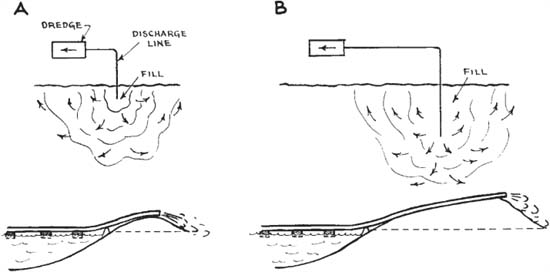
FIGURE 14.42 Open hydraulic fill.
FIGURE 14.43 Discharge pipe pattern.
Fills are likely to be somewhat firmer in the immediate vicinity of the discharge than farther away, because coarser particles tend to settle out first.
Pipe joints are often rather out of line when connection is first made. They are straightened out two or more lengths back from the discharge opening, usually by prying into better position and blocking up. A straight line reduces friction on the load and wear on the pipe.
Leaks at joints are quite common. They can sometimes be stopped by tightening the connection or prying the pipes into better position. They can be checked by forcing in the thin ends of shingles. Those on the bottom block themselves with spoil without requiring attention unless the pipe is on a trestle.
In general, pipes lying on the ground do not need to be hooked together as the friction in the joint and with the ground holds them together. However, on curves and at changes in grade, fastening is necessary.
Individual joints are fastened by winding wire around the pipe hooks, which are placed in line with each other, and twisting it tight with a short stick which is left caught against the pipe. On curves only the outside hooks need fastening.
If the line is on a trestle, each joint must be fastened on both sides.
A number of joints may be fastened at a time with a cable. It is looped and clamped, or fastened in any manner to both ends of the section to be strengthened, put under the hooks on one side of the first joint, over the top of the pipe to be caught, under the opposite side on the next, and on alternate sides to the other anchor. The cable becomes tighter with each joint, and if the correct slack has been allowed, can be slipped over the last few joints only by means of a bar. Another method is to leave it loose enough to go over all hooks easily and then use a load binder to tighten it.
Light cable, 3/8- or ½-inch (9.5 or 12.7 mm), is most satisfactory, but heavy, worn-out swing lines are often used.
Hydraulic fills may be built by a dredge as wasting operations to dispose of unwanted spoil from channel dredging, they may be a secondary but valuable part of the work, or the dredging may be done merely to get the fill.
Open Fill. The simplest type of open hydraulic fill is shown in Fig. 14.43. Spoil is being wasted on an area large enough that the water deposits practically all its burden when allowed to flow freely away from the pipe. A small percentage of the soil is fines which remain in suspension and drain back into the dredging area.
The end of the discharge pipe is supported on a low, light horse, or a log, or any object that will keep it above the fill. It may or may not have baffles to spread the stream. The stream will first erode slightly where it strikes the ground, but deposit the heaviest particles immediately around it and lighter ones farther away. In this manner a cone will be built up. Average slopes may be as steep as 15 percent for chunky material or as flat as 3 percent for silt. A high content of solids will give a steeper slope than a light burden of the same material. The action of the flowing water will sort and pack in the pieces.
When the fill has built up to grade or to a point where it threatens to interfere with the stream, another horse is set up, a pipe length is brought forward, the stream is diverted to another line, or a signal is sent to the dredge operator to stop the pump, and the pipes are connected.
The surface may be a slope up from the start of the fill, or level. In either case it should be made as smooth as possible to simplify keeping pipe gradient and to save future grading work. If the material is so coarse that it tends to build up a series of cones, the pipe may be set on a trestle and window pipes used. If the openings can be closed, a series of them can be used with open ports only in the last one or where needed. If the ports are simply slots, the window pipe must be taken off and replaced at the end of the line when it is lengthened.
Settling Basins. If the proportion of suspended particles in the runoff water is large enough to constitute a serious waste or to cause undesirable silting where it is discharged, or if the edge of a fill is to be steeper than the natural slope, then the water must be retained or ponded in the fill area long enough to permit settlement. This is done by construction of dikes across the natural direction of flow. These may be permanent seawalls or berms thrown up by a dragline or dozer. See Fig. 14.44.
Berms must be of ample height and heavy enough not to be pushed out by pressure, even when softened by soaking. Dirt must be thoroughly tamped or puddled around the spillway.
The amount of settlement obtained is determined by the turbulence in the settling pool, the length of time the water remains in it, and the fineness of the particles. The first two factors are largely fixed by the proportion between the area and depth of the pool, and the rate of inflow. As the fill progresses, the area will be reduced. This may be counteracted for a while by raising the water level by putting more boards in the outlet gate, but ultimately additional land will have to be inundated if settlement is to be obtained.
Where the bottom being dredged includes known areas of fine and coarse soils, the fines may be worked first while a large settling area is available, and coarse deposits used to complete the fill.
Dams. The velocity of the soil-water mixture discharged from a dredge pipe drops rapidly after it hits the ground because it spreads over a widening area and the water soaks into the fill. The stream may immediately lose its ability to carry cobbles, drop the gravel a few feet farther on, then the sand. Varying quantities of silt and clay may be carried after the water comes to rest in a settling basin.
FIGURE 14.44 Filling behind a wall. (Courtesy of Ellicott Machine Corporation.)
This results in a gradation of material, from coarse at the pipe through finer sizes with increasing distance. The separation is not clean, as some fines are trapped near the pipe and some coarse particles are rolled or carried by occasional currents well into the edges of the cone.
An earth dam must have the impenetrability of clay and the slump resistance of gravel. One way to meet these requirements is the construction shown in Fig. 14.45. A water-resistant core of clay, silt, and fine sand is supported and protected by gravel sides.
This cross section can be obtained by the proper selection and placing of hydraulic fill. The bank material must have a higher proportion of fines than needed in the dam structure to allow for the amounts left in the coarser material and that carried away in the wastewater.
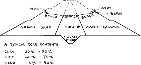
FIGURE 14.45 Cross section of earth dam.
The dam is built up in a series of low fills. Berms are built by dragline or dozer along the outer edges of the fill, and discharge lines run inside them. The spoil builds up in a slope or beach from the outer line down to a central settling basin called the core pool. Coarse particles remaining in the stream are ordinarily deposited immediately upon entering this calm water. Occasionally, concentrated runs of water may build sand or gravel tongues out into the pool. This possibility is guarded against by anchoring beams or other floats just offshore, where they will break up such formations.
The core pool water is drained into a pipeline or flume, which is usually on one of the outer slopes and is built up as the dam level rises. The width of the core is regulated by that of the pool.
The Mud Cat, Figs. 14.46 and 14.47, is made in two models designed especially for cleaning mud deposits and weed growth out of shallow ponds and canals.
Its carrier is a specially designed barge, 30 or 39 feet (9.1 or 11.9 m) long and 8 feet (2.4 m) wide, which draws only 21 to 27 inches (53 to 68 cm) of water. A pair of side pontoons, connected by a floor and end bulkheads, are filled with polyurethane foam. The space between them is occupied by a 175-horsepower (131 kw) diesel engine, a dredge pump with an 8-inch (20.3-cm) inlet and a 6-inch (15.2-cm) discharge, and accessories, controls, and a cab.
The suction boom has a hydraulic hoist. It carries an 8-foot- (2.4-m) wide auger driven by a hydraulic motor. The auger is partly enclosed while working by a mud shield. Single layers up to 18 inches (46 cm) thick may be removed at one pass. Maximum working depth is 10½ feet (3.2 m) for the smaller machine, 15 feet (4.6 m) for the larger.
The dredge is propelled by a capstan winch and a  -inch- (7.9-mm) diameter cable. The cable feet is placed ahead of time, and anchored. After each pass it is moved 6 to 8 feet (1.8 to 2.4 m) and reanchored. This arrangement minimizes the equipment needed on the dredge, and can ensure complete coverage of the area.
The suction line and the mud shield together ensure that most of the material loosened by the auger or the shield will be drawn up into the dredge, so that little turbidity (which may be injurious to fish and other pond life) is caused, in comparison with draglines and other excavators.
The auger is able to chop up water weeds and reasonable amounts of trash. If jammed, it can be lifted to the surface and cleaned. The shield tends to support it against digging too deeply into the bottom.
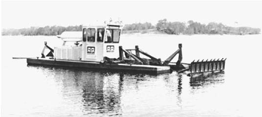
FIGURE 14.47 Suction head auger and mud shield.
The pump has a capacity of 2,000 gallons (7,600 liters) per minute against a 155-foot (47.2-m) head, and can transport ½ mile (805 m) or more without a booster. Removal of solid material may be at the rate of 50 to 120 yards (38.2 to 91.8 cu.m) per hour.
In dredging cleanout of ponds in built-up areas, two critical problems may be to get enough water to supply the pump and float the carrier, and to obtain adequate sites for settling basins. Both problems may be reduced by use of mechanical and/or chemical means to accelerate separation of water and solids.
Water Supply. An enclosed body of water may be sucked dry by a dredge, unless it is large or is fed by generous stream flow, or its water is returned to it after separation of the solids.
Reuse or clarification of water may be desirable or required in order to avoid damage to drainageways or other property from overflow of a settling pond.
Processing that accelerates separation of water and solids favors both efficient recycling of the water, and disposal of any surplus.
Cyclone. The cyclone, Fig. 14.48, is a machine that is widely used in mineral processing plants to dewater finely ground material during or after processing. It has no moving parts, and is operated by the force of the water-solids mixtures that are pumped into it.
In the design shown, mixed water and solids enter a cylindrical chamber at a tangent. Pressure of about 22 pounds per square inch (1.5 kg/sq.cm) is sufficient to give the fluid high rotary speed. Centrifugal force presses solids against the outer wall, along which they move in a downward spiral, through a conical section, to an underflow or discharge gate. Water, with any solids too fine or too light to separate from it, overflows through a pipe at the top.
Adjustments for sharpness of separation and/or thickness of underflow mud may be made either manually or automatically during operation. Efficiency in separating fine or light particles diminishes as machine size increases.

FIGURE 14.48 Cyclone, cutaway.
Their separation range would enable them to remove all gravel and sand, a substantial fraction of silt, and some clay, with a variable proportion of organic material. Unfortunately, they tend to leave in the water precisely those materials that take longest to settle, and which demand the largest quiet water area for separation.
However, under many conditions they remove most of the bulk, outside disposal of which can make it possible to use a settlement basin for a much longer time.
Solids from the underflow usually contain enough water to make a flowing mud, which may have to be channeled, dragged, or pumped to a drying area, or hauled away in tight-bodied dump trucks.
Clotting. Organic mud, with or without included fine mineral particles, takes days and sometimes weeks to settle out of water naturally. But the addition of certain chemicals, called polymers, causes such material to form into relatively large clots which sink promptly, leaving clear water in 20 to 30 minutes.
Excellent results appear to follow injecting the polymer into the dredge outlet pipe about 20 feet (6 m) short of its discharge point.
Hydraulicking may be said to be a dry-land dredging operation. Banks are washed down by high-pressure water jets and the mixed spoil and water moved by gravity, pumps, or both, to a fill. It is used in building hydraulic fill dams when sufficient material cannot be obtained by dredges, for breaking down banks, for cleaning rock for blasting, and for various special conditions.
Plant. Hydraulicking equipment consists of water pumps, suction and discharge lines, monitors, and a flume or sluiceway to carry the mixed water and soil.
The centrifugal water pumps may be high-pressure jet types, or medium-pressure types, set in series with one pump’s discharge supplying the intake of another. Usual pressure is between 80 and 150 pounds per square inch (5.6 and 10.5 kg/sq.cm), but up to 275 psi (19.3 kg/sq.cm) may be used.
Steel or iron pipe is used except near the monitors, where flexible hose is required.
Monitors, also called giants, are large, high-pressure nozzles mounted in swivels on heavy skid frames. Small sizes may be aimed by hand, large ones have a movable baffle which utilizes the power of the stream of water to turn the nozzle.
The sluiceway may be a gully of controlled width in the pit floor, a flume of wood or metal, or dredge discharge pipe. A gully should have a slope of at least 4 percent, but flumes can be somewhat flatter. A narrow, deep waterway will give maximum velocity and transport the greatest bulk of solids.
The high-pressure water may do the transporting, or additional water may be supplied by low-pressure pumps or gravity flow.
The sluiceway runs into a distributing pipe which takes it to the fill. This pipe should start high enough on the slope to give sufficient head to push the spoil through it.
Hog Boxes. If the grade is not sufficient to carry the spoil from the pit to the fill, it is poured into a hog box, which is a concrete trough. From there a dredge-type pump moves it through a pipeline to a fill.
When gravity feed is not possible and the hydraulic fill method is required on the dam, dirt may be dumped through grizzlies into the hog box by trucks, washed into a sump by monitors, then pumped to the fill.
Operating a Monitor. The primary requirement of dam hydraulicking is the correct selection of material. Definite proportions of fines, sand, and gravel are usually required, and these are often not found in a single bank.
Several monitors may have to work in different sections, or in different pits, and increase or decrease their part of the output on the direction of the job inspectors.
If the bank will cave if undermined, the monitor should be as close to it as safety permits, and the stream should be directed at the base. If most of the cutting can be done at an angle, efficiency is increased and danger from slides is reduced.
If the bank will not cave, it is best cut by standing at such a distance that the stream will just start to bend downward before hitting it.
As the bank recedes, the monitor must be moved forward. The flexible hose should be long enough to be laid in loops so that considerable movement is required before an extension is needed.
Sometimes draglines, bulldozers, or other machines are used to break up the soil and push it into the sluiceway.
Water jets will erode very hard soils, but not efficiently. Light blasting of clay will greatly increase production.
Cleaning Rock. Fire hose and nozzles supplied by small centrifugal pumps can often be used to advantage in cleaning thin layers and pockets of dirt off rock which is to be drilled. Pressures of 20 to 100 psi (1.4 to 7 kg/sq.cm) may be used. Several workers will be required to handle one nozzle and hose.