
Revolving shovels were the first important power excavators. Part-swing, steam-powered dipper models mounted on railroad cars or barges were in use over 150 years ago.
Other models—clamshell, dragline, and backhoe—were gradually developed. In the first 20 years of the 1900s, steam power was largely replaced by internal-combustion engines and electric motors.
Also, full-swing replaced part-swing, and crawler self-propelled mountings became standard. More recently, rubber-tire carriers have become common.
Until around 1950 practically all these machines manipulated their buckets by means of cables (wire ropes), winding onto mechanically or electrically driven drums. Swing and travel depended on gear arrangements. Controls were mechanical, air, hand or foot pressure hydraulic, or combinations of these systems.
By 1975, production of cable and mechanical drives in backhoes had been largely replaced by hydraulics in all but large mining excavators. Hydraulic-operated cranes and booms are standard among smaller machines, and the hydraulic clamshell has gained acceptance. Also, the hydraulic excavator has replaced the dipper shovel in most kinds of work.
As a result, the importance of the cable-operated excavators has declined greatly, particularly among small machines. However, they are dominant as draglines, clamshells, and big cranes and dipper models.
Structure. A shovel has three structural divisions. Anatomically, the top or revolving unit is the head and torso, the mounting or travel unit is the legs, and the various attachments are the arms and hands. A revolving unit and a travel unit together make up a “basic shovel.”
There are five attachments (also called rigs or fronts) which have primary importance. These are known best under the names front shovel (or dipper stick), backhoe, dragline, clamshell, and crane. They are shown in their age-old forms in Fig. 13.1.
A basic shovel has three sets of machinery. One of them is made up of deck-mounted drums which are fitted with spools for cable or hydraulic pumps and hoses to rotate and stop the deck by clutches and brakes. These also control the in-and-out and up-and-down movement of the bucket for digging and dumping.
The second set rotates (swings) the deck, upper machinery, and front end around a center pin. The upper unit is supported by rollers or balls on a circular track or turntable, and is rotated by a vertical pinion gear that meshes with bull gear teeth in the turntable. It “walks” around the bull gear, swinging the shovel as it does so. The gear is controlled by a reversing clutch (a unit consisting of two friction clutches and a set of bevel gears), which can turn it in either direction.
FIGURE 13.1 Shovel rigs and mountings.
This mechanism is an important factor in the efficiency and adaptability of the shovel. It enables it to face in any direction for digging and dumping, and to move loads quickly anywhere within its reach. Comparatively few wearing parts are involved, none of them work in the dirt, and friction losses are slight.
The third power train provides means to walk or propel the shovel. A vertical shaft extends downward through the deck and the hollow center pin to drive a horizontal axle, which has a clutch and a brake on each side. These may be of either jaw (tooth) or friction construction. A pair of sprockets on the ends of the outer axles drive the tracks through roller chains.
The propel mechanism is controlled by a reversing friction clutch set, usually the same one that controls the swing. A few machines have an independent travel shaft and clutches. Truck mountings depend entirely on the truck for travel.
When one set of friction clutches controls two or more functions, jaw clutches are shifted to connect the power train that is to be used, and to disconnect the other.
Small shovels use gasoline, diesel, or electric engines, with mechanical drive to all moving parts. Large shovels may use diesels, with mechanical or electric drive; or several electric motors supplied from “high lines” through a cable.
The engine is fitted with a disc clutch, so that it can be cut off from the machinery. It may also have a torque converter, that serves to cushion it against shocks, to reduce lugging down, and to give additional power in hard digging.
There may be a two-speed engine transmission, chiefly to allow faster travel.
Size. There have been light shovels with ¼-yard (0.19 cu.m) buckets, and ¾-yard (0.57 cu.m) is a very useful and popular size weighing around 20 tons (18,000 kg). The largest models, used in strip mining, have dipper buckets up to 140 or more yards (107 or more cu.m), or draglines over 200 yards (150 cu.m), and weigh thousands of tons (kg).
The revolving unit, or superstructure, is built on and around a heavy steel deck or bed plate. This carries the machinery frame, which may be welded to it.
The deck is supported by the swing rollers which rest on the turntable of the travel unit. It carries the engine, transmission, and operating machinery.
A diesel (or, less commonly, gasoline) engine or an electric motor is mounted across the back. Drive from its clutch, converter, or transmission shaft, with mechanical connections or hydraulic pumps and tubing, run the mechanism. In either case, it has a reduction ratio that makes the deck machinery turn more slowly than the engine.
In Fig. 13.2 the deck machinery for a shovel outfitted for a clamshell or dragline operation is shown with various alternatives. The power unit is either an internal-combustion (IC) engine or an electric motor. The drive chain from the motor is a silent chain, which turns the swing shaft (reversing shaft), which also serves as a transmission shaft, driving the intermediate and drum shafts through a small gear on its opposite end.
In Fig. 13.3 the excavator is controlled by a hydraulic system. There are two joystick-type hand levers and two foot pedals. These control raising or lowering the boom and other movements required in excavating operations.
Propel Shaft. A layout with hydraulic power is shown in Fig. 13.4. The swing shaft is used only for swinging.
At the lower end of the vertical swing shaft is a pinion (small spur) gear which meshes with the large internal toothed bull gear in the travel unit (see Fig. 13.14) which gear is centered on the vertical propel shaft. The propel shaft terminates in a bevel gear that meshes with a bevel (ring) gear on the live axle, which drives the tracks through chains.
Figure 13.5 shows a deck layout with separate propel and swing.
If a live boom is not required, independent swing allows any rig but a front shovel to walk without any shifting of jaw clutches, thus saving most of the time in move-ups. With any rig, it will allow simultaneous control of walk and swing, which saves time and effort in restricted spaces.
Some large draglines are equipped with a walking shaft that is independent of all other functions. Such machines cannot be readily converted to shovel use.
Large Mine Excavators. The revolving frame design for a large [20- to 80-cubic-yard (15- to 61-cu.m) bucket sizes] excavator with electric motor power is more involved than the smaller shovels described previously. The deck frame has multiple deep-section vertical members welded to heavy top and bottom cover plates. This forms a rigid mounting deck for the hoist and swing machinery. The machinery deck arrangement may be as shown in Fig. 13.6.
A distinct difference from the smaller shovels is the use of two motors for the hoist and two for the swing motion. These provisions are to give quick reactions to load change capability. The electrical inertia, or resistance to change of motion, of the motor armatures is proportional to the square of their diameters. Therefore, smaller-diameter armatures will make changes considerably faster than one large one. That means two motors with smaller armatures will have a quicker cycle time than if there were just one larger motor for each of these functions.
FIGURE 13.2 Deck machinery for cable operation.
FIGURE 13.3 Hydraulic controls in an excavator. (Courtesy of The Gradall Company.)
A-Frame and Gantry. The deck A-frame consists of a triangular frame of angles or tubing on the deck on each side of the machinery, and a cross bar slightly above the cab roof which carries sheaves for the boom support line. See Fig. 13.7.
Larger shovels require higher supports for the boom cables. When the A-frame projects high above the roof, as in Fig. 13.8, it is called a gantry. Gantries, and some A-frames, are of folding or collapsible construction so that they can be lowered by hand or power for shorter booms, or to go under obstructions.
Boom Foot. The boom foot is a pair of hinge brackets on the reinforced front edge of the deck. Booms are attached by horizontal pins running through these brackets so that they can pivot up and down, but are held from side movement.
Cab. The cab is a shell of sheet metal and glass, designed to protect the machinery and the operator from the weather, but also to give the operator as much visibility as possible to the work area.
FIGURE 13.4 Hydraulic swing and traction circuits.
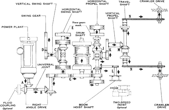
FIGURE 13.5 Deck layout for cable operation.
FIGURE 13.6 Large shovel machinery deck arrangement. (Courtesy of P&H Mining Equipment.)
Controls. The operator’s seat may be on either side of the deck, forward of the center. Levers and pedals or pushbuttons controlling all functions of the machine are near it. A representative set of controls is shown in Fig. 13.9 for a mechanically driven cable machine.
In the cable-controlled machine, the hoist lever engages the hoist clutch when pushed forward. The lever is held back by a light spring, but when pushed forward beyond the point necessary to engage the clutch, it locks over center, and requires a pull to disengage it. Use of this level rotates the hoist or front drum so as to wind in the cable attached to it.
The digging, drag, or crowd lever, when pushed forward, engages the clutch of the same name, winding in cable that forces the bucket into material being dug. If used with a dipper stick, it can be pulled backward from center also, engaging the retract clutch. These movements are made against spring tension, and both clutches lock over center.
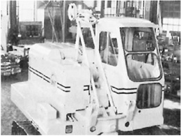
FIGURE 13.7 Circle vision cab and A-frame.
FIGURE 13.8 Gantry boom cable support. (Courtesy of P&H Mining Equipment.)
The boom hoist lever, when pulled back, engages the boom clutch, causing the boom cable to wind in and raise the boom. In center position, it releases this clutch and allows an automatic brake to lock the boom drum. When pushed forward, it releases the brake and allows the weight on the cable to turn the boom drum as fast as the drum shaft turns. There is also a ratchet which can be set to prevent the boom cable from paying out at all.
The swing lever, when pushed forward, engages the front swing clutch and causes the shovel to swing left or, in walking position, causes it to move forward. When pulled back, this lever engages the other swing clutch, with reversed results.
The swing lock, when pulled back, engages a toothed lock with the bull gear and prevents the shovel from swinging. The swing-propel shift lever, when forward, engages the jaw clutch for swinging. When back, it connects the walking jaw. In the middle, both are disengaged.
The hoist brake locks or slows the rotation of the hoist drum; the drag brake does the same for the drag drum. These brakes are held in released position by springs, but can be locked down by engaging with a ratchet. Pushing on the top of the pedal locks it, on the bottom releases it.
The throttle regulates the speed of the engine by changing the governor setting. The steering lever is used only when walking. Forward turns to the right, backward to the left, center straight ahead, in forward motion.
The engine clutch is used to disconnect the machinery from the engine, for safety when adjusting or lubricating with the engine running, and for starting when cold.
FIGURE 13.9 Operator’s mechanical control station.
The digging lock will lock the shovel tracks when pushed forward, will release them when pulled back, and in the center will allow the shovel to move forward only.
Controls are different in each make of shovel. Many use vacuum, air, or hydraulic controls, with shorter operating levers. Steering brakes are generally used to hold for digging also, and may be applied by hand or automatically. The direction of throw of operating levers can often be reversed.
The two-lever “joy stick” controls in a hydraulic-controlled shovel are shown in Fig. 13.10.
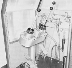
FIGURE 13.10 Hydraulic control station.
In a large, electrically controlled mining excavator, the operator may have a programmable message display (PMD) module, as shown in Fig. 13.11. This is true with the P&H Electrotorque system, which automatically converts incoming high-voltage ac power to the controlled dc power that operates the motor armatures. Once the module is programmed, the operator would only have the buttons on the PMD panel to push to control the operations of the shovel.
Swing Rollers. The whole weight of the revolving unit and attachment rests on rollers. These are tapered so that they can follow the circular turntable without any part dragging. Bushings or antifriction bearings are used.

FIGURE 13.11 Electric controls for large mining excavator. (Courtesy of P&H Mining Equipment.)
FIGURE 13.12 Separate swing and hook rollers. (Courtesy of Harnischfeger Corporation.)
In Figure 13.12 the swing rollers carry the load only, and hook rollers stabilize the machine. Adjustment is made in the hook roller brackets.
Figure 13.13 shows a single row of balls with each race forged in one piece. This is assembled without the balls, that are then fed with their separators through a hole in the inner race. The hole is then plugged. Dirt is kept out of this oversize bearing, and lubricant retained in it, by upper and lower neoprene seals.
Counterweight. The weight of the attachment and its load are balanced by putting the center of rotation in the front center of the deck, so that the engine and most of the deck machinery are behind it. In addition, counterweight may be placed in the rear of the revolving unit in pockets behind the engine, or in a band around the rear of the deck, outside of the cab. The exposed counter -weight makes an effective bumper and guard for the rear of the machine, but adds to its length, or tail swing.
Counterweight can be added or taken away to suit different applications.
Lubrication. Most of the deck machinery may be enclosed in oiltight cases, and lubricated by gears dipping oil out of one or more reservoirs and carrying it to distribution points, from which it flows over the other gears and bearings and back to the reservoirs. The oil level should be checked often through inspection plugs.
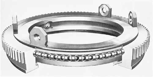
FIGURE 13.13 Ball race turntable.
The turntable gear is greased with asphalt-base lubricant. This may be thinned and pumped through a deck-mounted dispenser, or thinned or heated and poured through a hole in the deck, while revolving the upper frame. The gear should be checked at least once a day, and greased whenever bright spots appear on the teeth.
Pressure gun fittings throughout the shovel are greased in accordance with a schedule supplied with the machine. In general, bushings require more frequent attention than antifriction bearings, some of which may be sealed so as not to require lubrication. The crowd chains for the dipper stick should be kept painted with oil or light grease, but the tracks and drive chains should be left dry.
Many shovels may be purchased with three different types of travel unit—crawler (track or cat mounting), truck mounting with two engines, and rubbertire self-propelled, as shown in Fig. 13.1. The crawler is the most widely used and will be described first.
General Construction. The crawler chassis, shown in Fig. 13.14, is made up of a turntable welded to a frame consisting of two heavy I beams, called dead axles, that connect two heavy truck frames which rest on the track wheels and are surrounded by the track.
The travel unit is considered to have the bull wheels in the rear and the idlers in the front, regardless of whether this corresponds to the front and rear position of the revolving unit.
Live Axle. The three-piece live axle, Fig. 13.15, runs across the upper frame, parallel to the frame axles. Near its center is a bevel gear, which is driven by the vertical propel shaft. On each side of this are steering clutches, with the inner jaws fixed to the center section of the axle.
Steering. If both axle jaw (steering) clutches are engaged, rotation of the vertical propel shaft will turn both tracks equally. If the right clutch is disengaged, the left track only will drive. The effect on the machine’s direction of travel will be determined by the steepness or roughness of the footing, and friction in the right track. On firm level ground the machine will move straight forward, or a little to the right; on steep upgrades or on rough ground, it may turn quite sharply to the right. If the right axle is locked by the brake, the right track will stop, and the left one will walk in a circle around it, turning the machine very abruptly. Turning in soft material is difficult, as the locked track digs in. On slippery surfaces one or both tracks may skid, preventing accurate steering.
Turning to the left involves engaging the right-hand clutch and disengaging the left one, and perhaps locking the left side if a sharp turn is desired. A gradual turn may be made by use of the clutch alone, by partial application of a friction brake, or by a succession of short, sharp braked turns with straight runs between.
If the machine is moving down a grade steep enough that its engine is holding it back rather than pushing it forward, the steering action of the clutches will be reversed; that is, disengaging the right clutch will cause the machine to turn to the left, as the disconnected track can roll faster than the one connected to and held back by the engine. When the brake is used, steering is about normal regardless of grade.
The machine should be stopped before engaging or disengaging the jaw clutches or brakes. While they are transmitting the engine power to the tracks, they are almost impossible to disengage; and when apart, they might be damaged by being forced into engagement while the jaws are turning at different speeds. The machine is stopped by partially engaging the friction clutch that would move it in the opposite direction or by using friction brakes. In an emergency a ratchet lock or jaw brakes can be used for stopping, but this is very jarring to the machinery.
The steering method is the same going backward (toward the bull wheels), except that for a turn in the same compass direction the opposite clutch and brake are used.
FIGURE 13.14 Lower frame and tracks.
FIGURE 13.15 Propel power train in base.
Tracks. Most excavators and other machines do not depend on the tractive pull of their crawlers for their ability to work. It is made up of a number of identical shoes cut and drilled at their ends so that they can be fastened together by pins.
Track Behavior. Refer to Fig. 13.16. If the machine moves forward, the bull wheel will turn so that the teeth will mesh with the pads under and ahead of it, picking them up one by one and passing them around its rear and then forward over its top. As the bull wheel moves forward on the track, it pushes the truck frame and the idler ahead. The idler, pressing against the track in front of it, pulls on both top and bottom sections, but since the bottom is pinned down beneath the shovel, and is pulled tight by the bull wheel, the idler pulls in the track from above about as fast as the bull wheel supplies it from behind, and turns it back to the ground, where it stays, supporting the truck wheels and weight of the shovel until picked up by the bull wheel again.
If the machine is walking backward, the mechanism may behave in two ways. If the footing is good, and the grade nearly level, the bull wheel will pull in some slack from the top of the track and pass it underneath, moving backward and pulling the truck frame and idler after it. The track it has turned underneath supports the shovel and is then carried up by friction with the idler.
If the footing or grade is such that there is insufficient traction in the pads directly underneath the bull wheel to move the shovel, they will be skidded forward against the rear truck roller, the bull wheel will pull the upper track tight, and it will pull the idler backward. The idler moves truck frame, shovel, and bull wheel backward.
There are several reasons why a shovel or other tracked vehicle should be walked forward when possible. In forward motion, the track is laid smoothly along the ground, and its slack hangs harmlessly in gradual curves in the top section. The heavy strain is on the short piece from the bottom of the bull wheel to the first truck wheel supporting a good share of the shovel’s weight. In reverse movement, the track may be kinked in one or more damaging angles which the truck rollers must climb over or push down, and the traction stress is on the whole distance from the top of the bull wheel to the front slope of the idler, causing excessive wear and danger of breakage.
Multiple Crawlers. Very large stripping shovels may weigh several thousand tons (metric tons). They usually travel and work on the surface of coal seams that have limited resistance to crushing and shearing.
They may be supported on four crawler units, one at each corner of the lower frame. Each unit includes a pair of crawler frames and tracks, and an ac drive motor.
Universal mountings, that allow oscillation of individual tracks and swiveling of the whole unit for steering, connect the crawler units to massive hydraulic jacks that support the lower frame, and automatically keep it level on uneven ground.
Travel and steering controls are located on the lower frame.
Two-Engine Truck Mounting. The revolving unit may be carried on a turntable fastened to a truck chassis. The truck engine is then used for traveling, and the shovel engine for digging. Ordinarily, the shovel controls for walking, steering, and traction braking are disconnected or missing. Occasionally, however, arrangements may be made to connect the shovel engine to the wheels through the truck transfer case, and to steer and brake the truck from the shovel cab. This mechanism is used for short moves at low speeds in the working area.
Any standard truck chassis of sufficient rated capacity can be used to carry a shovel, although considerable extra bracing is required, and better service should be obtained from a chassis specially engineered for the shovel. Tandem drive gives best support, and all-wheel drive is advisable in work where mud or sand may be encountered.
FIGURE 13.17 Power trains in truck mountings.
The truck should have the right-hand side of the cab cut away, to make it possible to carry the boom forward at a low angle. The frame and the rear axle should be a single rigid unit while digging. Springs may be eliminated, locked during work, or replaced by stabilizer bars in the tandem construction.
The truck-mounted shovel can ordinarily swing in a full circle, but with most attachments can work through only 270° because of interference of the cab and the truck front.
Figures 13.17 and 13.18 indicate various power trains used in the trucks.
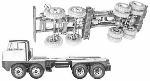
FIGURE 13.18 8 × 4 truck carrier.
FIGURE 13.19 Cutaway of hydraulic outrigger.
Outriggers. Outriggers are used to increase stability. These may be beams which can be slid or folded out of the bumpers, usually only at the rear, and which are supported by blocks or jacks. They provide a much larger and more rigid base than the tires. When they are used, lifting capacity is greater than that of a crawler of the same size, particularly when working off the back so that the truck engine acts as a counterweight.
Platforms may be put under the blocks to give support when working on soft ground, and the jacks may be used to lift the wheels out of mud or sand pockets.
There are also power outriggers, as in Figs. 13.19 and 13.20. A curved arm with a hinged ground shoe is moved outward and downward, or inward and upward, by a hydraulic two-way telescoping ram. The set of four can be used to steady, level, and even to lift the machine.
These outriggers are individually controlled from the truck cab. Automatic locking wedges relieve the hydraulic rams of strain during work, and prevent settlement that might be allowed by fluid leakage.
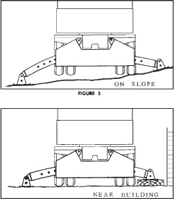
FIGURE 13.20 Using hydraulic outriggers.
Uses of Truck Mounting. The advantage of truck mounting is its capacity for rapid and inexpensive movement from one job to another. With many models, the shovel can be placed and locked in traveling position in less than a minute, and then moved along roads at 20 to 35 miles per hour (32 to 56 kmph).
This is a pleasant contrast to the slow and laborious job of loading and securing a crawler type on a trailer, and unloading it at its destination.
On the job, however, the truck-shovel suffers from lack of maneuverability. Instead of turning in nearly its own length, like the crawler, it must have considerable space in which to turn or sidestep.
Its most important weakness for excavation work is the ease with which it can get stuck. Even with all-wheel drive, its ability to get in and out of soft spots is inferior to that of a crawler, and with rear drive only, constant care must be exercised to keep it out of trouble in soft ground and during rains.
Two-Piece Boom. For an excavator on wheels designed for travel on roadways, a two-piece boom is advantageous. See Fig. 13.21. It tucks up much tighter than the one-piece boom for travel between job sites. The two-piece boom uses a hydraulically adjustable base section that is pinned to the second boom section, which is also hydraulically controlled. In turn the second boom section is pinned to the stick.
Self-Propelled. The rubber-mounted, self-propelled shovel is a third type. It is, in effect, a compromise between the crawler and truck mountings. It can utilize any front-end attachment.
The revolving upper is similar to those found on crawler mountings, except for different controls for steering, brakes, and stabilizers, which in this machine are power hydraulic.
It is manufactured as a short-chassis, two- or four-wheel drive carrier, with dual wheels front and rear. There are no springs. The front axle is connected to the frame by an oscillating mechanism that can be leveled and locked by power hydraulic stabilizers. The rear axle is bolted solidly to the frame.
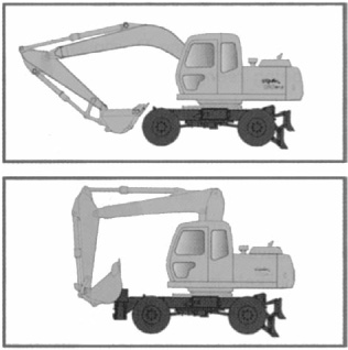
FIGURE 13.21 Comparing booms for mobile excavators. This illustration shows how much tighter the two-piece, hydraulically adjustable boom (bottom) tucks in for driving, compared to the standard one-piece boom (top). Illustration courtesy of Hyundai.
Maneuverability on the job is subject to the same limitations as the truck, except that the short wheel base, and in some models four-wheel steering, allows it in tighter places. It is permitted to travel on highways, but for long trips it is better carried on a trailer.
Like its cable-operated counterpart, the full-revolving hydraulic excavator may be said to be made up of three structures: the revolving deck unit, the travel base, and the attachment. See Fig. 13.22.
In hydraulic machines these distinctions remain clear only while considering the frames, arms, and other mechanical parts. The hydraulic system is operative in both deck and attachment, and often in the base as well.
Technology has advanced such that the machine automatically calculates the hydraulic requirement for a given load or lifting situation. When the operator anticipates a particularly hard digging condition, he or she can touch a button to increase the hydraulic pressure requirement. In some excavators this increase is limited to, say, 7% for 10 seconds, but in others the increase may not be limited until the operator hits the button again.
The technological changes have resulted in as much as 20% better fuel efficiency. If that saving is effective for a year of 2,000 hours and diesel fuel costs $3USD per gallon, that would be a saving of $6,000 annually.
This discussion will first cover the mechanical arrangements, including the placement of the principal hydraulic units; and will then deal with the generation and distribution of the hydraulic power.
The revolving unit consists essentially of a heavy rectangular steel deck, formed and reinforced to carry engine, pumps, attachment, controls, and cab; and to rest and revolve on a turntable. Some parts are heavy steel plate and specially shaped ribs and bases, others may be open girders.
The center of rotation is usually forward of the center. The area of greatest strain, and therefore of heaviest construction, includes this spot, the mounting hinges for the boom just forward of it, and the hinges for the hoist cylinder(s) on the front edge of the deck.
The forward location of the rotation center places the major part of the deck weight at the rear, where it serves to counterbalance the weight and pull of the shovel or backhoe. This effect is usually increased by placing the engine and pumps across the rear.
Counterweight. In addition to counterbalancing by arrangement of parts, there is usually a massive counterweight of shaped iron attached to the rear of the deck outside the cab. This may be very heavy, up to almost one-fifth of total excavator weight.
The swing axis is centered in the travel unit, so that the front of the deck is set back from the front of the tracks, and the rear edge overhangs. This overhang is increased by the counterweight.
There is even greater overhang at the side, when the top is swung 90°. This overhang or tail swing must be allowed for in placing the excavator for work.
It is sometimes desirable to remove counterweight, to suit a lighter attachment, to reduce tail swing, or to lighten the machine to move it across a bridge of doubtful strength or to avoid overloading a trailer.
Most of the larger machines provide standard or optional means to handle counterweight by engine power. There may be a pair of hydraulic cylinders mounted on the back, with connections to a valve and pump.
Engine. Standard power is diesel, from less than 100 horsepower (75 kw) to over 1,000 (746 kw). While bigger machines have bigger engines, there does not seem to be a standard ratio between power and either machine weight or bucket capacity.
FIGURE 13.22 Hydraulic front dipper shovel. (Reprinted courtesy of the Caterpillar company.)
There is now development of a hybrid excavator by manufacturer Doosan, which should result in cost savings. The machine is to be equipped with a diesel engine, electric swing motor, electric converter, and an ultra capacitor to store excess energy during turning and light-duty operations. The reserve electricity can then be used to assist with the power of the engine needed during heavier work.
Drives. One or more hydraulic pumps may be driven directly by a shaft behind the clutch, in line with the engine crankshaft. But it is perhaps more usual for the pumps to be offset from this shaft, in a group of two or more, with drive-through gears. See Fig. 13.23.
Most of these machines have hydraulic drive to all functions. Cylinders operate parts directly, or through simple levers. Motors drive through reduction gears and sometimes through more or less extensive mechanical arrangements also.
Figure 13.4 shows hydraulic-mechanical arrangements for swing and propel in a hydraulic power system.
Cab. The cab may be almost identical with that for a cable shovel. It is always of the circle vision type, with the roof higher than the machinery covering. Windows have shatterproof glass for weather protection and vandal resistance. Some windows may be fixed, others may be moved by cranks or on slides, or removed after loosening bolts.
There may be a skylight or roof window, which is helpful in watching out for wires and tree branches.
Standard cab location is on the right front corner of the deck, beside the boom. However, it may be on the left side. Controls for all phases of machine operation, plus gauges and warning lights, are grouped here.
Pumps and Circuits. Most of the engine power is usually delivered to a set of hydraulic pumps, which provide pressure flow of fluid to power the functions of the machine.
Three types of pump are used—gear, vane, and axial piston (hydrostatic)—in various combinations. Some machines have only two pumps—one for power and one for cooling—and others have as many as five.
Multiple pumps are desirable to provide a fixed and dependable flow of fluid for the use of each of several functions, so that one cannot be robbed (deprived of flow and pressure) by the opening of another circuit.
FIGURE 13.24 Hydraulic circuits.
On the other hand, a pump is expensive, it consumes some power (and therefore fuel) when it is idling, and may be inefficient when run at part capacity. It is therefore economically desirable to provide it with as much useful work as it can handle.
These opposed needs are met in a variety of ways, including the use of variable-output pumps and proportioning valves, and the design of sequences to feed circuits that are important, and starve others that are less important at the moment.
The most desirable arrangement for both production and simplicity of operation is a separate circuit for each function that takes care of its normal needs, plus means to temporarily borrow fluid from another circuit. (See Fig. 13.24.)
Differences are too numerous and changeable to justify detailed discussion here. But the operator who is changing from one machine to another should be prepared to find differences in response to controls, particularly when two or more are used at the same time.
Layout. A revolving excavator has a rather complex hydraulic system, but fortunately it has enough space in which to arrange it. The engine and pumps are usually across the back; the swing motor and its vertical shaft must be above the big swing gear in the carbody. If the control valves are directly operated, they must be in the cab. (See Fig. 13.25.)
Otherwise, components can be arranged for efficiency, access, and convenience.
Lines. The basic piping on the deck and along the boom and stick is apt to be high-strength tubing, factory-formed into the lengths and curves needed. Where parts move in relation to each other during work, lines connecting them must be made of flexible hose. Hose may be used in other parts of the piping, for ease in installation, or to avoid stresses if parts shift slightly in position.
Stick and bucket lines must allow for very sharp bends. The length needed at sharp angles forms loops as the bends are straightened or reversed.
FIGURE 13.25 A typical deck layout.
If hydraulic motors or other units are in the travel unit, a swing joint is installed at the center of revolution. This device, described in Chap. 12, provides for flow of hydraulic fluid regardless of the rotation of the upper unit. It requires a flexible or cushion mounting for one or both sleeves, to avoid distortion when digging strains cause the deck to rock slightly on the turntable.
Controls. A bewildering variety of operator’s controls are offered. They vary in arrangement of levers and pedals, and in the means by which they operate the valves. (See Fig. 13.26.)
Levers are usually self-centering, that is, they return to neutral or Hold position automatically when released. A propel stick may have a detent to hold it in full-on position. Brakes may have finger-released latches to hold them in On positions. (See Fig. 13.27.)
Simple pedals are spring-returned to Off or neutral, like an automobile’s accelerator or foot brake. Swing and traction brake pedals may have hold-down latches.
FIGURE 13.26 Joystick controls, hydraulic excavator.
Rocker pedals are hinged at the center. Pressing down on the front opens a valve to cause a member to move. Pressing the back moves the same part in the opposite direction. A spring returns it to neutral from either position.
Cylinders are either naturally self-locking when flow of fluid is blocked, or can be made so by an automatic check valve. Hydraulic motors may or may not have a braking effect when shut off, but they cannot be depended upon to hold parts against creep. Positive braking may be supplied by a friction brake. This may be operated by a pedal. If automatic, it is engaged by spring pressure, and released by hydraulic pressure when the motor is used.
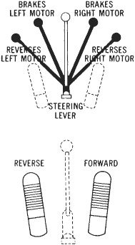
FIGURE 13.27 Travel and steering.
The control lever, pedal, or button may be connected mechanically to the valve that it operates, by cable or rod-and-clevis linkage. More often, a fluid system is used. In small machines, this may be static like a hydraulic brake system, with or without power boosters. Larger machines may use power from a constantly running hydraulic pump, or air, or combinations of static hydraulic with air or pumped hydraulic. Different methods may be used in one machine.
Direct connection is simple and prompt. If valves are excellently balanced and leverage is adequate, this is a highly satisfactory arrangement.
Power controls should make the fineness of balance of the operating valves less important, but their own smoothness may be questionable. However, a power system usually means less operator effort, and less lever or pedal motion for a given effect.
Power Management Systems. Most of the medium-to-large excavators now have a power management system so that the operator can control the power his or her machine applies for the work. The operator selects the mode that matches the kind of work to be done.
There may be three to five modes in the system to produce the most efficient hydraulic power distribution and fuel economy for the operation. One may be the heavy-duty mode for speed and optimum productivity, another mode may be standard for general excavation and fuel economy, still another mode may be for light work, where control and fuel economy may be most important, and finally, a mode for extra fine work: lifting, sloping, and grading.
For example, the light or extra fine mode might be set for deep digging using laser instruments to automatically dig to a preset depth and slope. Sensors set between the bucket and stick, between stick and boom, and between the boom and machine measure the angles. By monitoring these angles the laser controls send commands many times per second to electrohydraulic valves installed on the machine. These valves meter the precise hydraulic oil requirements to the cylinders. The operator follows the guidance of the laser controls unless he or she disengages the system. Refer to Grading Instruments on Equipment in Chapter 2.
The use of the different modes are controlled by electronics on board set by the operator. The electronics can also set the environment in the cab for the operator’s comfort while doing the work at hand.
Terex has an arrangement for a laptop computer connection to record pump pressure and engine speed in its excavator, which can be displayed graphically and printed, for a permanent record. It also installs in the cab a viscous-sealed mounting system designed to absorb vibrations and reduce noise.
Most full-revolving hydraulic excavators have crawler mountings. However, they can be adapted to truck carriers and self-propelled wheel mountings.
Carbody. The carbody is a massive frame that includes the turntable and the dead axles or cross members that transmit its weight to the track frames. It carries the large ring gear that engages with the swing pinion extending downward from the deck frame.
Tracks. Track frames are single or double beams welded to the outer ends of the dead axles in the carbody. Either of two types of track may be used. One is the traditional linked-shoe construction. The other follows the crawler tractor design of a roller chain with bolted-on shoes. Shoes are usually of the semigrouser type with three low cleats.
Drive wheels, idlers, and rollers conform to the type of track.
Propel. The propel, traction, or travel drive to the tracks may come from a pair of live axles set across the center of the carbody, or from a pair of reversible hydraulic motors fastened to the track frames.
Axles are usually driven by a hydraulic motor on the deck, through reduction gears, a vertical shaft, and bevel gears. However, a hydraulic motor may be located in the axle housing, and turn them through a reduction-type transmission.
In the axle mechanism, a pair of brakes and jaw clutches provide for steering while traveling, and for holding the machine while working. Control is usually hydraulic. Friction brakes may be used instead of jaws.
Hydraulic motors, usually of the hydrostatic (axial piston) type, can be mounted in any convenient location on the inner surface of the track frames, and connected to the bull wheel axle by sets of reduction gears.
Direct-mounted hydraulic motors permit independent track movement on two sides. This makes possible counterrotation on the tracks for the spin turns discussed in Chap. 12. This feature makes it easy to turn in the length of the machine with little ground disturbance, and to maneuver accurately in very restricted spaces.
Most hydraulic excavators are designed for hoe use only. The hoe might therefore be considered as an integral part of the machine.
However, it can be taken off and put back on, there are often options in stick length, and it may carry working tools other than hoe buckets.
Present capacity of buckets ranges from less than ½ yard (0.38 cu.m) to over 20 yards (15 cu.m).
Construction. All hydraulic hoe attachments are made of three strong structural members: the boom, the stick, and the bucket. These are hinged to each other, and the boom is hinged to the excavator deck. Movement at each of these hinges is controlled by two-way hydraulic cylinders.
Boom. The boom is almost always of the bent or gooseneck type, concave toward the ground. It usually has one bend or angle, but may have two.
This shape serves three purposes. It allows space to pull the bucket closer to the machine, permits deeper digging without interference from the tracks, and enables the operator to see past it more easily when it is raised.
The boom foot is hinged to massive trunions 2 or more feet (0.6 m) back from the deck edge. They are usually in front of the swing center, but may be behind it.
If there are two points of attachment to the boom, the upper one is used for maximum digging depth, the lower for maximum dump height.
The outer end of the boom is usually prolonged into a two-piece bracket, in which the stick is held by a heavy hinge pin or pins. The stick cylinder is mounted on the boom top.
Stick. The stick, dipper stick, or arm is hinged to the end of the boom, and is connected to the stick cylinder rod at its upper (back) end, and to the bucket and bucket dump arms at the bottom or front. It is usually one-piece, but may extend and retract by telescoping.
The stick’s connection to the boom is much nearer the top than the bottom of the stick. The proportion between the two sections varies widely in different makes and models.
The bucket teeth will be moved by the stick cylinder 4 to 8 times faster and farther than its piston moves, with one-fourth to one-eighth the force.
Some machines provide two places for the boom-to-stick hinge. The one that is closer to the bucket will supply more power for hard digging; the other will provide more speed in easier work.
The motions of the stick are variously described. Extending the cylinder forces the bucket in toward the machine, crowding it into the digging.
FIGURE 13.28 Backhoe bucket details.
Bucket Mounting. The bucket, which will be described below, is connected to the lower end of the stick by a hinge pin, and to a triangular set of paired dump arms because the bucket has such an extended arc of rotary movement around the stick hinge.
When the cylinder is extended, the bucket teeth move inward in a curling or digging motion. When it is retracted, the bucket opens or extends.
Several sets of holes may be provided, so that bucket action can be changed by moving hinge pins. The choice is between a combination of greater speed and range of movement in bucket control, or slower motion and greater digging and breakout force. Selection depends on the work being done and the operator’s preference, and is likely to be changed only under unusual conditions.
Buckets. The bucket is sometimes called a dipper or a tool. The primary use of a backhoe is digging ditches, although it is also well adapted to digging basements as discussed in Chap. 4, and general excavation. See Fig. 13.28. For efficiency in ditches, the bucket should cut the full required width on every pass. Therefore, buckets are usually supplied in a number of widths, ranging generally from 30 to 48 inches (0.76 to 1.22 m) but available for some models down to 24 inches (0.61 m) and up to 5 feet (1.5 m).
Narrow buckets tend to be deep in proportion to width, and may fill poorly in chunky or rocky digging. If width is the same, reducing depth from the front edge reduces capacity, but may increase efficiency in loading enough to compensate. A standard-width bucket intended for very hard digging might be made smaller (shallower) so that it could be reinforced without adding too great a weight.
The bucket is usually slightly wider at the open or front end, to reduce friction at the sides and to allow for easier dumping. Additional clearance from trench walls may be obtained, and bucket cutting width increased by 2 to 8 or more inches (5 to 20 or more cm), by installing sidecutters. They may be fixed-width or adjustable, smooth-edged or toothed.
FIGURE 13.29 Hoeclamp or power grip for use on excavators. (Courtesy of Amulet Manufacturing Co., Inc.)
Sidecutters are useful in accommodating a bucket to a wider trench, cramming more dirt into a narrow bucket, reducing drag in sticky soil, and reducing wear on the front edges.
Wide buckets may have poor penetration. General-purpose buckets for basements and pits are usually intermediate in width and capacity.
A bucket may be replaced by a single ripper tooth. This is intended for loosening and breaking, rather than excavating, but in certain soil types it may be able to cut a very narrow ditch for cable installation.
The digging edge is almost always equipped with teeth, which are removable for reversing, sharpening, or replacement.
Other Attachments. Excavators are made to be very versatile machines with the variety of attachments that can be used on them. Many of the attachments are for excavation type operations. These include: the hoeclamp for handling stumps and boulders (Fig. 13.29), and the hydraulic breaker (Fig.13.30) for breaking up rocks or other hard objects. Some other commonly used attachments to show the versatility of the hydraulic excavator for excavation operations are shown in Fig. 13.31.
FIGURE 13.30 Hydraulic breakers used with excavators. Smaller hydraulic hammers are available for carriers such as backhoe-loaders, while larger units fit excavators in excess of 100,000 pounds (45,000 kg).

FIGURE 13.31 Other attachments for hydraulic excavators. (Courtesy of Construction Equipment.)
Figure 13.32 shows the Gradall, a special type of full hydraulic pull shovel. It resembles a conventional shovel only in the construction of the turntable and swing rollers, and in having the engine mounted on the rear of the deck.
The engine drives a three-unit tandem pump that supplies pressure through control valves actuated by hand levers and foot pedals, to hydraulic cylinders and motors which power all working functions.
The boom is a hollow box girder, one section of which telescopes inside the other in response to the push and pull of a long two-way ram. It is mounted in a heavy steel cradle that serves for support, control, and counterweight. Cradle and boom are raised and lowered by two double-acting cylinders based on the platform. The boom can be lowered to a vertical position, for 25-foot (7.6 m) digging depth, and raised to dump at over 18 feet (5.5 m). It can also be tilted (rotated on its long axis) in either direction from the horizontal by a hydraulic motor.
Swing is controlled by hydraulic motors driving reduction gears (See Fig. 13.3). These control such movements as extending or retracting the boom, and rotating the boom and bucket to do digging, as shown in Fig. 13.32, and reaching the bucket out to dig and pulling it in to get a full load. With a crawler-mounted excavator, there are controls for moving the tracks individually, together, or in opposite directions for pivoting at a specific spot.
All hydraulic valves are spring-loaded so that they return to a neutral Hold position as soon as they are released. Affected parts stay locked in position until the controls are moved again.
Operation. The normal digging procedure is to swing the machine and extend the boom until the bucket is over the spot where digging is to start, lower the bucket in digging position, pull it inward with the boom retract until it fills, rotate it to closed position, then lift the boom and swing it while extending or retracting as necessary to position the bucket over the dump spot. The bucket is then opened to dump, and the boom swung back to the digging.
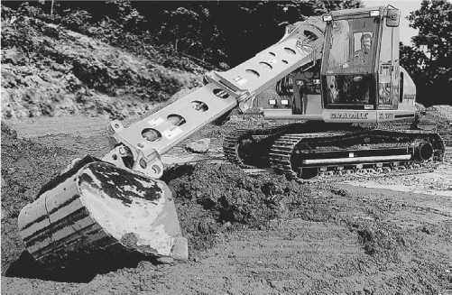
FIGURE 13.32 Side sloping. (Courtesy of The Gradall Company.)
The first few passes may be made by starting with the teeth at an angle of about 45° with the ground, and flattening it as it is pulled in. If the slice is too thin, a steeper angle may be used; if too thick, a flatter one. It is good operation to fill the bucket in the shortest pull that does not cause the engine to lug down or the carrier to shift.
The bucket should be closed when full and lifted out of the ground. Swing must not be started until it has lifted clear. If spoil is being dumped right alongside the ditch, it may not be necessary to close the bucket fully, and swing will be very short. If dumping is into a truck, it should be as near the ditch as possible, and swing may not be started until the bucket is high enough to clear the truck.
The ditch is deepened and cut toward the carrier by a series of similar passes. The far end can be trimmed to a vertical slope for a short distance down by opening the bucket wider; but if the ditch is deep, there will be a curve at the bottom that cannot be reached from this position. However, the carrier can be moved backward far enough to cut a square end (if it is needed), as there is ample clearance between the nearest part of the ditch and the carrier.
The bottom of the ditch is finished by making the final pass with the bucket level, using the hydraulic down pressure of the boom. This cleans up soil spill, evens out irregularities and tooth marks, and leaves an excellent surface for pipe or granular material.
If a boulder or heavy root is encountered, it may not be practical to remove it by direct pull of the boom retract. Much greater force can be applied by putting the bucket in a level or down-tilted position, getting the teeth under the obstacle, and closing the bucket. The floor will act as a fulcrum to aid the teeth in prying the object up, providing a powerful breakout force without dragging or tipping the machine.
When a boulder is too large to be pried out in this manner, it is necessary to widen the ditch until it is freed. A ramp is dug from it to the ground surface, the carrier is moved ahead a short distance, and the retract used to drag or roll the stone to the surface, where it can be rolled to the side.
Heavy lifts and any side pushing or pulling should be done with the boom retracted to obtain additional force and reduce strain.
Grading. These machines are particularly well adapted to finish grading. The retractable boom makes it possible to draw in a bucket or grading blade in a smooth line that is not disturbed by hinge action of a boom or the effect of bumps on wheels or tracks. Its reach ranges from 30 feet (9.1 m) from center pin in the small machine with a standard boom to almost 45 feet (13.7 m) in the large model with a boom extension for mine or tunnel scaling work.
When doing light grading up or down a slope, the bucket or blade is kept in light contact with the ground as it is drawn in by the telescoping boom. When the ground is below the level of the boom pivot, retracting tends to pull the bucket up, so that for a level grade the boom-lowering valve must be kept partly open to compensate. If the ground slopes steeply upward, the boom may have to be lowered as the bucket moves in, to keep a straight-line contact.
The bucket or blade may be tilted to follow an uneven contour, or to work an even contour from a side angle.
Hydraulic control permits keeping the bucket at its most efficient digging angle at any point in its reach, and dumping just where desired. With the boom tilt it gives precise control, and allows exact cutting of floors and sloped or vertical walls in cellars and ditches. It is adept at shaping and fine-grading roadsides under even difficult conditions, and can stay safely on the road as it works.
Pull-type buckets are available in widths from 15 to 72 inches (0.4 to 1.8 m), and the digging action of push buckets resembles that of a front-end loader bucket with remote control. There is an 8-foot scraper blade for grading where dirt does not have to be picked up, and a ripper for breaking pavement or loosening hard dirt. (See Fig. 13.33.) Boom extensions and offset booms can be obtained.
This machine can dig deeply in a small area, so that it can connect ditch sections from the side (see Fig. 5.3), and dig for septic tanks and manholes with little or no overcutting. It can push as well as pull and has the advantage of being able to reach under overhead structures.
FIGURE 13.33 Buckets and attachments. (Courtesy of The Gradall Company.)
Volvo Construction Equipment has developed a set of excavators designed specifically for handling pipelaying jobs. This equipment is designed to replace the tractor or dozer with a side boom perhaps 20 to 28 feet (6.1 to 8.5 m) long to handle pipe. The Volvo excavator has 360-degree swing capability, allowing the operator to face the pipe at all times. With a wider track gauge and lower center of gravity it is more stable than the tractor with a side boom. And the Volvo boom is 30 to 38 feet (9.1 to 11.6 m) long allowing it to work farther from the pipe trench to avoid caving the trench walls
The excavator has an electronic Load Management System giving constant computerized load charts for the 360-degree rotation and infinite equipment geometries up to a 35-degree grade. The operator interacts with the monitoring system via a graphic display in the cab. Load indicator lights, clearly visible on the boom, provide warning if the loads approaches the pipelayers tipping capacity.
The compact excavators with zero tail swing configuration first appeared in Europe and Japan but now are widely used in the United States. Basically, the upper body of the machine rotates within the footprint of the tracks, except for the boom. Refer to Fig. 13.34A.
FIGURE 13.34A Mini-excavator with dozer blade for stability.
The overall compact design of the mini-excavator allows it to move into places where larger machines can not go. The width of tracks of the smallest machine can be retracted to a 29 inch (0.74 m)width so it can go through a 36-inch (0.91 m) wide gate for work in a backyard. It can operate in narrow easements or even inside building basements.
The boom of a mini-excavator rotates independently of the upper body so that it can work close to a wall or foundation. See Fig. 13.34B. And an existing machine can have the frame tilted by up to 15 degrees, as seem in Fig. 13.34C, in case the supporting ground is not level.
The tracks of a mini-excavator can be expanded to give it more stability. A dozer blade on front can be lowered to the ground improving the stability of the machine for digging. See Fig. 13.34A. Rubber tracks help minimize damage to landscaped areas and walkways.
The compact excavator is able to travel on muddy, wet ground better than a heavier backhoe-loader be -cause it delivers a lower pounds- per-square-inch (kg per sq.cm) force on the ground.
The mini-excavator is small enough that it does not need a heavy trailer or large truck to move it long distances. It can be loaded on a trailer with other pieces of equipment.
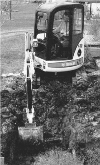
FIGURE 13.34B Mini-excavator boom swing separate from cab.
FIGURE 13.34C Mini-excavator with tilting capabilitity. Frame-tilt allows vertical sidewall digging.
It is said that a compact excavator is easier to operate than a backhoe-loader, which is discussed in Chap. 16, because it has simple and logical controls for quick learning. Manufacturers have added powerful engines and load sensing hydraulics. There are standard auxiliary hydraulic lines that allow the use of a variety of hydraulically driven attachments like those discussed earlier.
Mini-excavators are made in sizes weighing from 1,500 to 18,000 pounds (680 to 8,200 kg) and can dig from 5 feet to over 12 feet (1.5 m to over 3.7 m) deep, just short of the common 14-foot (4.3-m) depth for a standard sized hydraulic excavator. Refer to the section on Compact Loaders and Excavators in Chapter 16.
A dragline attachment is shown in Fig. 13.35. It has a long light crane boom, with a fairlead set at its foot, and a bucket attached to the machine only by cables.
Boom. The boom is of lattice construction. It may be of welded steel angles, angle corners and tubular braces, or all tubular. Very long booms sometimes use aluminum sections near the tip.
Each boom is made up of at least two sections, tapering from their bolted center connection toward the end. The bottom is reinforced to hinge on the boom foot pins, and the top to hold the point sheaves.
Additional sections, usually in lengths of 5 or 10 feet (1.5 or 3.0 m), can be placed between the upper and lower sections to obtain extra reach or dumping height.
If the boom is intended for dragline work only, it carries one large sheave on the point; but if it is to be used for a clamshell also, it has two. A smaller sheave is carried on each side for the boom support line.
Fairlead. The fairlead is a device mounted on the boom or boom foot, which lines up the drag cable to spool smoothly onto the drum, even when the bucket is far off to the side.
A common type, Fig. 13.36, has the front pulleys mounted in a frame on a vertical hinge, and a pair of vertical sheaves in a frame behind them.
FIGURE 13.35 A large dragline.

FIGURE 13.36 Four-sheave fairlead.
FIGURE 13.37 Dragline bucket. (Courtesy of Erie Strayer Company.)
Bucket. Figure 13.37 is a picture of an Erie general-purpose bucket, which is somewhat similar to a pull shovel bucket without stick fastenings and side cutters. A pair of drag chains is attached to the front of the bucket, through brackets by which the pull point may be moved up or down. The upper position is used for deep or hard digging as it pulls the teeth into a steeper angle.
The drag chains converge in a drag yoke to which the drag cable is fastened. The hoist (bail) chains are attached to pivot (trunion) pins toward the rear of the bucket sides, rise vertically to a spreader bar, then converge to fasten to the dump sheave housing, which in turn is fastened to the end of the hoist cable.
Dragline buckets are made in various weights: light ones for digging soft earth, and rehandling stockpiles of material; medium-weight for general work, and heavy and extra heavy for deep and rocky digging. A light bucket means less weight to be lifted each cycle; a heavy one has better penetration and wear resistance. Light buckets may sometimes be obtained with a toothless cutting edge which is excellent for stripping soft topsoil, grading, and cleaning up.
Perforated or sieve buckets are standard buckets with a number of holes cut in the back and sides. These are useful in wet digging as water is pushed through the holes by incoming dirt and any remainder drains out while the bucket is being lifted. Water can be almost entirely manipulated out of a standard bucket if it is possible to take a deep bite so that a massive chunk of earth will push it out, particularly if the bucket can be pulled up a steep bank to dump any remaining water. However, if it is not possible to get a good bite, the perforations are necessary to avoid profitless carrying of water and sloppy spoil piles or loads. Very thin mud or fine dry soil may be lost through the holes, but most digging, wet or dry, can be handled.
Some operators weld ⅜- or ½-inch (9.5- or 12.7-mm) chain in the rear corners of solid or perforated buckets, as the slapping of the loose ends helps to dump sticky soil and to clean out thin layers remaining on the bucket sides and bottom and in corners after dumping.
The effectiveness of penetration of a dragline bucket decreases with depth below the machine, as the drag cable then pulls in a more upward direction, raising the teeth out of the soil. This can be compensated for in part by reversing or sharpening the teeth; by using a longer boom which, by permitting digging farther from the shovel, decreases the upward angle of the drag cable; or by fastening the drag cable higher on the bucket. Larger and heavier buckets dig much better at the same depth and distance.
Choice of bucket size is determined by the materials to be handled and the length of the boom. For example, a ¾-yard (0.57-cu.m) machine usually has a 40-foot (12.2-m) boom and uses a ¾-yard (0.57 cu.m) general-purpose bucket. However, if the material to be dug is very heavy or tends to come up in amounts greater than the bucket capacity, if a longer boom is used without extra counterweight, or if digging is so hard or abrasive that a heavy-duty bucket is needed, then ⅝-yard (0.48-cu.m) capacity should be more satisfactory. The same machine might use a 7/8- or 1-yard (0.67- or 0.76-cu.m) light bucket on a standard boom in handling coal or dry humus.
Reeving. The dump cable runs from the top of the bucket arch over the dump sheave and forward to the drag yoke.
The boom line is a standard four-part rigging, similar to the dipper boom support, except that a longer cable is needed. The hoist line runs from the hoist drum over a large boom point sheave and down to the dump sheave case. The drag cable runs from the drag (digging) drum through the fairlead to the drag yoke. See Fig. 13.38.
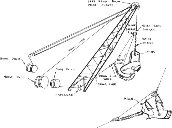
FIGURE 13.38 Dragline reeving.
Some machines have a light multiple line from the boom hoist drum to a hanging padlock sheave set, and a heavier two-part line from there to the boom point.
This shortens the inner cable, which is most subject to wear. One inner line can be used with different boom lengths.
Bucket Action. If the bucket is lifted with the hoist while the drag cable is slack, it will hang in fully dumped position. If tension is then put on the drag cable, it will pull on the dump cable before the slack is out of the drag chains. The dump cable will pull the front of the bucket up, toward the dump sheave, as seen in Fig. 13.38. Releasing the drag cable will allow the dump cable to run back over the sheave, and the bucket will return to dump position, pivoting on the hoist chain pins.
If the bucket is then lowered to the ground, it will turn to a horizontal position, or will rest on its teeth and arch, depending on its balance. A pull on the drag cable will now tip the bucket forward or backward onto its teeth, and the teeth and lip will dig in as it is dragged toward the shovel. If the pull is continued with the hoist line slack, the bucket will cut to a depth determined by its weight, the angle and sharpness of its teeth, and the resistance of the soil. If so deep a cut is not wanted, some tension is put on the hoist line, raising the bucket slightly. If the dump cable is long, the bucket will be raised in the rear by the hoist chains. A short dump line will cause an upward pull on the arch, raising the front of the bucket as much as or more than the rear. In either case the depth of cut is reduced. A further pull on the hoist will raise the bucket clear of the ground, as seen in Fig. 13.39.
Whether the bucket will remain in the carrying position, or partially dump while being raised, depends on opposing forces acting through the dump cable. The weight of the bucket front pulls down on the arch end of the cable, and the tension between the hoist and drag cables tends to stretch its drag-yoke-to-dump-sheave section and pull the bucket up. In effect, the dump cable must pinch the other two cables together in order to obtain slack to drop the front of the bucket. This pinching requires comparatively little force when the angle between the cables is small and becomes increasingly difficult as the angle flattens out. Also, if the dump cable is long, it will not have to pull as strongly on the two cables to obtain slack as if it were short. The action of the bucket will therefore depend on the angle between the hoist and drag cables, the length of the dump cable, and the weight and distribution of the bucket load.
A wide angle between hoist and drag cables can be had when picking the bucket out of the soil, either by pulling the bucket close to the shovel, or by keeping the boom at a low angle. Bringing the bucket all the way in usually wastes time and causes wear on bucket and chains which might be avoided if it were picked up as soon as full. A low boom has a tendency to tip the shovel when heavily loaded, and often cannot be used because of obstructions or height of dump. A short dump cable makes it difficult to dump except directly under the boom point. If a live boom is used, it is possible to dig low and dump high, but this takes extra time and work.
The technique used will depend on the job and on the operator’s preference. There is generally at least one good method of handling any situation.
Digging. In an ordinary dragline digging cycle, the bucket is not thrown or cast. It is lowered into the pit with both lines taut, the hoist brake being almost wholly released, then reapplied smoothly as the bucket is about to strike the ground, and the drag brake is released enough to allow the bucket to drop straight instead of following an arc centering on the fairlead.
When the bucket rests on the ground, the hoist cable is slackened slightly and the drag clutch engaged. The drag cable pulls the bucket, with the teeth digging in and cutting a slice of dirt which piles inside the bucket. If the hoist brake is locked, the bucket will move up in an arc centering on the boom point, and on level ground may pivot so the teeth dig more sharply but no longer have the full weight of the bucket to force them in.
Ordinarily, the hoist brake is released enough to let the bucket cut level or follow the pit contour. If the pit slopes up toward the shovel, which is the most favorable digging condition, it may be necessary to partially engage the hoist clutch to avoid digging in, or to prevent the hoist line from becoming too slack and allowing the chains and dump sheave to slump into the bucket.
Hoisting. When the bucket is filled, the hoist clutch is fully engaged and the bucket is lifted clear of the ground. If the bucket has a tendency to dump, the drag may be left engaged until the angle between drag and hoist cables is sufficiently wide to hold it. The drag clutch is then released and the hoist is continued, with the drag brake applied just enough to allow the hoist to pull the bucket forward and upward under the boom, without slackening the lines enough to dump it. If the drag brake is applied too tightly, the bucket may hit the boom.
The swing is started as soon as the bucket is clear of the ground. This is the period of heaviest load in the dragline cycle, as the machine is simultaneously lifting a load, pulling against the drag brake with the hoist clutch, and swinging. If overloads are picked up in the bucket, they may so slow the line and swing speeds that less dirt will be moved per hour than if smaller bites were taken.
Dumping. Hoisting is discontinued as soon as the bucket is high enough to be dumped. When the swing is completed, the drag brake is released, partially or wholly, and the bucket swings out and dumps. A long dump cable will permit normal dumping inside the boom point, a short one under it only. Raising the boom will bring the dump point closer, lowering it puts it at a greater distance.
It is poor operation to raise the bucket higher than necessary before dumping. Clearance should be allowed so as not to strike trucks or other receptacles, but piles can be barely cleared. This saves time on a short swing and fuel and wear and tear under any circumstances.
Casting. If the bucket is to be thrown or cast, it is pulled close in by the drag cable during the swing to the pit, with the hoist line held at a length that will keep the bucket above any obstructions during the cast, as in Fig. 13.40. When the swing is completed, the drag brake and clutch are released and the bucket swings outward like a pendulum. When it is just short of the farthest point of this swing, the hoist brake is released and the bucket falls downward and outward (B). It is checked by gradual application of both brakes just before hitting the ground, as otherwise it might be damaged, overturned, or tangled in its chains. It should then rest on the ground in the same position as if lowered and respond to drag pull similarly, except that if the pit floor is level, the hoist cable slackens as the bucket approaches the boom point and tightens again after it has passed under it.
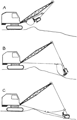
FIGURE 13.40 Casting the bucket.
A swing throw may also be used. During the swing from dump to pit, the drag cable is left slack and the hoist held so that the bucket is high enough to clear obstructions. The centrifugal force of the swing will pull the bucket outward, and the hoist brake should be released at the proper point so that the bucket will land where it is wanted. The swing should be checked as soon as the hoist brake is released, and hoist and drag brakes applied gently as or just before the bucket strikes. This swing throw requires much more expert operation than the other type and may damage the shovel seriously if improperly done.
Another technique is to make a pendulum throw while the shovel is swinging so that the centrifugal force adds to the outward sweep of the bucket.
Throwing to dump is a similar process, but usually the height of the piles prevents the use of a long enough hoist line to obtain much distance. The weight of the load, however, causes the bucket to cast farther than it could on the same length line if empty. A combination pendulum and swing throw is most effective, particularly if the shovel is dumping at 180° from the pit and can revolve in a full circle so that it can dump without stopping.
If the load sticks in a bucket which is thrown to dump, it may overturn the shovel.
The distance the bucket can be thrown is affected by the skill of the operator, the length and angle of the boom, the weight of the bucket, the depth of the pit, and even the wind. Casting onto a surface level with the tracks, the teeth ought to reach farther than the boom point would if lowered to a horizontal position. Much greater distance is attained when casting into a pit.
Manufacturers are wary about recommending or discussing throwing of buckets, because a careless operator may thus bang a good bucket into scrap iron in a short time, and the swing throw has possibilities for wrecking the boom as well. Beginners will do well to thoroughly master ordinary digging before practicing throws, particularly if they have trouble with tangled cables.
Throwing the bucket usually slows the digging cycle by several seconds, and reduces accuracy of work, so that digging should be done inside the boom point when practicable.
Tangles. If a drag cable becomes tangled, it is a good procedure to throw the empty bucket, as often the whole tangle can be unwound in this way, and at worst very few wraps will be left on the drum to be straightened. If the drag cable becomes bent or kinked so that it does not spool on smoothly, the bucket should be dragged in all the way a few times with a load to straighten it. If the bucket is swinging in the air, the drag should be wound in while it is swinging out and holding the cable under tension, and held while it is swinging in and the cable is slack. If the cable is running smoothly, this precaution need not be taken.
If the hoist cable becomes tangled, the bucket should be rested on the ground, the hoist brake released, and the machine swung. When the hoist cable is unwound past the tangles or to the anchor, the hoist clutch should be engaged and the swing clutch disengaged. The cable should then reel back properly, unless crushed or kinked, in which case tension should be put on it as it is wound in, by partially engaging the swing clutch to keep the boom from swinging back easily over the bucket.
The cables should not be allowed to run all the way out in a throw, for if the momentum of the bucket is stopped abruptly by the cable anchor, the anchor may tear out of the drum. Manufacturers often supply and specify a drag cable which is so short that it is unsafe for casting.
Novice Operators. To the novice, the dragline is apt to seem a very loose, rough, and contrary machine. Special provisions have to be made in every movement to keep the bucket from jerking and swinging, but these soon become automatic and very precise control can be obtained eventually. The beginner will obtain the best results by keeping the bucket fairly close in, except when actually digging or dumping, by making slow starts and slow stops when swinging, and dragging the brakes slightly to avoid spinning out the cables.
Bucket Wander. As the bucket is pulled in, it is liable to be deflected by irregularities and find a path considerably to one side of a direct line. Also, the shovel may swing by gravity during the haul-in if it is not standing level. In either case the drag cable will not be directly under the boom. The fairlead sheaves will put it in correct alignment for the drum, but if the angle is sharper than the fairlead pivot can meet, the cable will be dragged across the fairlead guard plate and will wear the cable, and wear or possibly tear off the guard. The shovel boom should be kept in line with the cable by the use of the swing lever.
Boom Twist. As a loaded bucket is lifted, the boom will tend to swing over it. However, if the boom is held to one side by the swing clutches during hoisting, or if a heavy, oversize load such as a stump is partially lifted, then dragged along the ground by the swing, a powerful twisting force is applied to the boom.
In order to give a long reach without prohibitive weight, a dragline boom is of light skeleton construction that is not intended to withstand heavy side and twisting strains. Sometimes a boom so strained will collapse, but more often will twist slightly, bending some of the cross braces particularly on the lower side. Once twisted, normal loads may increase the damage and failure will follow if the boom is not straightened.
A good ironworker is needed to properly repair such a boom; but if the bent members are angle irons, it may be kept in service quite a while by straightening them with a jack. A stout plank is placed inside the boom across the corner angles as a support for an automobile jack that can push the pieces straight.
This type of repair should not be attempted on tubular members as they lose their strength if flattened.
Applications. The dragline does not have the positive digging force of the front shovel and the backhoe; as the bucket is not weighted or held in alignment by rigid structures and can therefore bounce, tip over forward, or drift sideward when it encounters hard material. This weakness increases with depth, and is particularly noticeable in small machines, as the weight and bulk of a large bucket are insufficient to give considerable stability and penetration.
The dragline experiences its greatest difficulty in cutting down and is able to continue a deep cut opened by other machines or by blasting in much harder material than it could dig from the surface.
The outstanding advantage of a dragline over most other rigs is long reach for both digging and dumping, plus the ability to dig below the tracks. It has the further good point of a high cycle speed, being second only to the dipper stick in this regard. It will be preferred to the front shovel for truck loading where the earth is not too tough, and where the original grade is better than the new, because of water, mud rock outcrops, steep ramps, or other problems within the excavation. Because of its greater reach, it will be preferred to the backhoe in any situation where it is capable of digging the soil effectively, where precisely cut vertical sides are not required, and where there is room for it to swing.
The dragline is the only practical attachment for extensive digging in mud, as its reach enables it to handle a wide area from a single stand and the sliding motion of the bucket avoids trouble with suction. It is also the best machine for many stripping operations in which the spoil is high-piled away from the pit, but is rivaled by long-boomed dipper stripping shovels if the spoil is to be moved across a narrow pit as in some strip mining.
Draglines with skillful operators do an excellent job of topsoil stripping, grading, and spreading piles of earth, but except under wet conditions they do not usually do as well as bulldozers of comparable ability.
Production. In easy digging, dragline production should be between 60 and 90 percent of that of a front shovel of the same size if trucks are loaded on the same level. If trucks are in the pit, output may range from 70 to 100 percent.
In hard digging, dragline yardage falls off much more rapidly than shovel yardage because of weaker penetration. High banks also slow them when loading on their own level or sidecasting, because of the extra time required for hoisting.
In sidecasting, production on a volume-distance basis may be much higher than that of a front shovel.
Operation Suggestions. The following are suggestions for dragline operation:
1. Keep bucket teeth sharp and built up to proper size.
2. Keep dump cable short so load can be picked up well out from the dragline.
3. Dig in layers, not ditches.
4. Keep digging surface sloped up toward shovel.
5. Do not drag in so far that dirt or rocks pile up in a ridge.
6. Keep drag cable from working in dirt.
7. Pick up bucket as soon as it is full.
8. Do not pull drag yoke into fairlead.
9. Inspect bucket chains frequently, especially at ends, and have them built up or replaced if worn thin.
10. Inspect fairlead frequently—worn bushings or spacers may let sheaves wear and cut cable.
11. Salvage short pieces of hoist or drag cable for dump cable. If dump anchors are too small, hammer the cable flat or change the anchors.
12. Do not guide bucket by swinging the boom while digging—you may twist the boom.
13. Do not swing until bucket or load is clear of the ground—you may twist the boom.
14. For heavy loads use high boom and swing slowly.
15. If the shovel starts to tip dangerously, drop the bucket. Do not try to dump it as its outward swing increases the tip.
16. Do not pick up overloads in bucket if they slow the hoist and swing, or if they tip the shovel.
17. Do not slap bucket against boom while hoisting.
18. Work with machine level. If you cannot, load trucks at either the top or bottom of the swing. Loading is sloppy at the side as the counterweight swings the boom uphill as the load is dropped.
19. Do not work with a cable that is cross-wound on the drum.
20. Do not travel uphill with a high boom.
In both parts of this book, mention is frequently made of crawler machines “walking,” but this is with apologies to the true walking draglines (walkers), as shown in Fig. 13.41.
These machines are made in sizes of 5 yards (3.8 cu.m) and up, and are so slow and bulky that they must be taken apart for shipment by freight in most moves from one job to another. On the job, however, they are easily maneuvered, and have extremely small ground pressure.
They have a working base which consists of a wide, flattened cylinder called a tub, which rests on the ground and carries the turntable on its upper side. The walking mechanism is operated by cams or cranks, one on each end of a large-diameter, multiple-part shaft mounted across and extending beyond the sides of the upper frame and the tub. They are connected to the walking frames and the walking shoes. When the shaft is rotated, the shoes contact the ground, raise the machine, and support its weight as a movement or step is made. The rear lifts clear, and the front drags.
When the dragline is in normal operation, it sets on its base and the shoes are elevated as shown in (D). To move, the walking shaft is rotated clockwise, thus turning the crank from its upright position and bringing the walking shoes in contact with the ground, as in (A). The continued rotation of the shaft in the same direction transfers the weight from the base to the shoes and results in the leading (rear) edge of the base being moved upward. Continued rotation of the shaft causes the base to move backward and downward to again contact the ground, thus completing the step. The center of gravity of the machine is slightly forward of the shaft, so that only the back is raised off clear. Most of the weight is taken off the front, but it retains a steadying ground contact. The setting down is more gradual than the rise, to avoid jarring.
FIGURE 13.41 Walking dragline.
The process is very similar to that by which a person on their hands and knees progresses by resting their weight on their hands and swinging their body forward with feet dragging, then rests on their knees and toes while they moves their hands forward again.
Steering is done by lifting the shoes and turning the revolving unit until its rear faces the desired direction, then stepping off as described. This is probably the only steering device in heavy equipment which takes negligible power, does not tear up the ground, and permits turns of any desired sharpness under any footing conditions.
This easy steering and the light ground pressure made possible by the large area of the base are the special advantages of this mounting. They enable it to work in places dangerous or im -possible for crawler machines because of difficult terrain, soft footing, or nearness to loose downslopes.
The disadvantages are that they are slow, with top speed around ⅕ mile per hour (0.32 kmph), and are very wide, 30 feet (9.1 m) or more. They must be disassembled to ship from one job to another, and are at a disadvantage in the bottom of a pit, because of both their width and the fact that they must walk away from their boom, which might be blocked by a hill.
The clamshell front is a jack-of-all-trades. It can do most of the jobs the other rigs will do, although less efficiently, and in addition has its own specialties of digging deep, narrow, straight-sided excavations, and neat rehandling of materials.
Figure 13.42 shows this type of rig. It consists of a boom similar to that used for the dragline, with two boom line sheaves and two operating sheaves at the point, and a bucket hung from the operating sheaves by two cables.
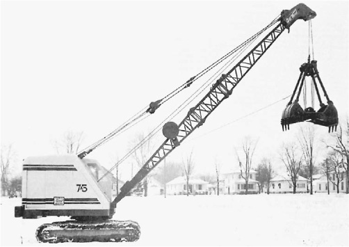
Buckets. A number of different types of clamshell buckets are available. Figure 13.42 shows a center pull construction, and 13.43 an Erie lever arm type. Each consists of two jaws hinged on a movable bar, the main shaft, and hinged on their outer ends to brackets extending to an upper bar, the head shaft parallel to the main shaft. The head shaft is supported by the head, or head beam, and the hoist cable. In Fig. 13.42, sheaves are fastened to each shaft and the digging cable is reeved through them and finally anchored to the head beam. In Fig. 13.43, the lower sheaves are on the lever arm, which is an upward extension of one jaw. If the digging clutch is engaged, the cable will pull the two sets of sheaves together, powerfully raising the center hinges of the jaws. Since the corner arms are fixed and will not allow the outer ends of the jaws to rise, the jaws pivot on their outer hinges and rotate inward and upward until they meet. The bucket is now closed, and will pick up its load if raised. If the digging line is released while the bucket is held in the air by the hoist or holding line, gravity will cause the main shaft to move down, pushing the jaws downward and outward and dumping the load.
These buckets, and certain other designs, can be obtained with various types of teeth with flat or curved lips, with toothless lips, with and without side cutters, with ballast plates for weight, and in various weights, widths, and shapes for special conditions.
The shovel manufacturer or dealer can supply a table of lifting capacities, and the weight of the bucket and load should not exceed their recommendation. Figure 13.44 shows the ways in which bucket capacity is measured. Line of plate is the usual rating.
The more resistant the earth to be dug, the heavier the bucket must be in relation to its capacity. A good, extraheavy-duty clamshell will dig almost anything except solid rock, but its closing action when fully reeved is very slow, and its massive weight reduces the payload. A light bucket, suitable for handling soft or loose dirt, will have faster action and a minimum of deadweight, but it will not penetrate hard materials, and will suffer damage if repeatedly banged and scraped on them. For miscellaneous work including both hard and soft, a medium-weight, general-purpose bucket is usually selected. Some of these have provision for adding or subtracting plates to change weight and strength.
A shovel can usually just handle a medium bucket of its own rated capacity; that is, a ¾-yard (0.57-cu.m) machine uses a ¾-yard (0.57-cu.m) bucket. In heavy-duty work, the next smaller size is used, and for very light rehandling, a size larger. A small bucket must be used in mud as suction holds it, greatly increasing the force required to start it upward.
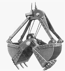
FIGURE 13.43 Lever arm bucket.
In general, teeth should be easily detachable, upper and lower sheaves should be shielded against dirt and should turn on high-grade bushings or antifriction bearings; the closing line should be guarded against sharp edges where it enters the bucket head; and it should be possible to reeve the bucket without using all the sheaves, and without throwing the digging line off center.
For other uses than excavation there may be additional factors to consider. One of the commonest uses for clamshells is for rehandling loose material such as coal, gravel, cinders, sand, etc., either in piles or in transfer to or from barges, freight cars, trucks, hoppers, and other receptacles. In this work the bucket should be able to remove practically all the loose material from a hard surface, and should therefore be wide and equipped with a straight, toothless lip. If the dumping point is high in relation to the boom length, a bucket with minimum top-to-bottom measurement must be used for maximum efficiency.
Clamshells may be used to handle large rocks, cordwood, and other bulky objects, as the pinching effect of the jaws gives them an excellent grip. There are special buckets made for these jobs which may properly be considered multiple-jaw clamshells.
Grapples. When a clamshell has more than two jaws it is called a grapple, star, or orange peel bucket. The jaws may be made to fit accurately to each other when closed, Fig. 13.45, upper, so either loose dirt or large objects can be lifted; or as independent tongs that will hold big pieces only, as in the lower cut. Both show a four-jaw Owen that is constructed so that each of these jaws can work independently, making it possible for each of the four points to get a firm grip on an irregular or off-center object.
FIGURE 13.45 Orange peel bucket and tong grapple.
The multitine grapple is made with loose joints, so that the tines are free to feel their way as they close. Loads can be gripped by their sides as well as by the points.
Reeving. Figure 13.46 indicates the reeving system. The hoist (holding) and digging (closing) lines are carried over the center pair of boom point sheaves and descend directly to the bucket. The hoist line is anchored to the head beam; the closing line goes through a guide in the head beam to the sheave sets. The bucket need not be fully reeved, as the full power of all the lines is not always needed. The cable may be anchored after rounding fewer sheaves for quicker but less powerful closing.
Tagline. The tagline is a light cable running from the boom to the bucket that serves to prevent the bucket from twisting or spinning in the air. It is kept on a light tension by a weight sliding on a track inside the boom, as in Fig. 13.46, or by a spring-loaded drum, such as the electric dipper trip previously described.
The cable is ordinarily fastened to two corners of the bucket by chains. If both are on one jaw, the hinge line of the jaw will be at right angles to the cable. If one corner of each jaw is held, the opening will be in line with the cable. The bucket can also be held in a diagonal position by attaching to only one corner.
The tagline pull is usually light enough that a person can guide the bucket by hand or with a stick as it is lowered to place it exactly as desired. This is done when it is necessary to cut in a position other than that in which the tagline holds it.
FIGURE 13.46 Clamshell reeving.
The same manufacturer builds a tagline with an extra drum for electric cable, for use with a magnet. Contact with the electric source is through brushes. The electric line is set slightly slack, the tagline taut.
There is also a magnet reel that has electric line only, which is taut at all times.
Digging. In digging, the bucket is placed over the work by swinging the boom, and either moving the shovel or raising or lowering the boom to obtain correct distance. The digging (drag, closing, or crowd) brake is released, causing the bucket to open, and the hoist brake is then released, allowing the bucket to contact the ground on its teeth. If the ground is soft, the hoist brake will be only partially released, or reapplied just before the bucket lands. If it is hard, the bucket will be allowed to fall freely, so that its weight will drive it into the ground for a good bite. In either case both brakes must be applied as soon as it has hit to avoid unspooling of the cable.
The digging clutch is then engaged to pull the jaws together. They first push the dirt inward, then curve and close under it. If the material is not too resistant and the bucket has proper weight, a full or heaping load will be gathered. The digging line will lift the bucket as soon as the jaws are tightly closed. The hoist clutch should then be engaged so that the hoist (holding) cable will not become slack while the bucket is being raised.
Dumping. The swing is started as soon as the bucket is clear of obstructions. The distance of the bucket from the machine may have to be adjusted by raising or lowering the boom if precise dumping is being done. This, of course, is practical only if the shovel is equipped with a live boom.
When the bucket is properly positioned, the digging brake is released, the jaws open by their own weight and that of the load, and the earth is dumped. The bucket is swung back to the pit in the open position and lowered or dropped for another bite.
Centrifugal force of the swing puts the bucket out beyond the boom point, offering some increase of reach for both digging and dumping. Stopping the swing will allow the bucket to swing inside the boom point for close digging.
Chopping. If the bucket does not fill at the first closing, it may be opened, hoisted, and dropped again, in which case the earth scraped together the second time will be added to that loosened the first time. This process may be repeated until a full bucket is obtained.
Signals. Clamshell work is often done at such depths that the operator cannot see the digging point. In this case it is best to have someone positioned to see the work and signal the operator. This is essential if there are workers in the pit where they might be hit by the bucket.
Hand Labor. If the bucket will not dig satisfactorily, either because it is too light in construction or slides off slopes, hand labor or explosives may be employed to loosen the dirt and the clamshell used to lift it out afterward.
Deep Digging. In deep ditches or shafts, it is difficult to keep the walls perpendicular, particularly if the earth is stony, as with each bite the bucket is edged a little away from the wall, thus causing the pit to grow narrower with depth. This tendency may be combatted by swinging the bucket against the wall as it drops, by hand trimming, or by making the top of the shaft enough oversize so minimum width will still be had at the bottom. It is helpful to equip the bucket with side cutters or corner teeth for this work.
Applications. A clamshell has the unique advantages of being able to stand on either the new its drums will carry, and at a height limited only by its boom length. It is the best of the rigs for handling bulky objects such as boulders, stumps, and logs, as chaining is usually unnecessary. It is the best tool for piling and burning loose brush and trees. It does not push or pull loose material to other positions as it digs. There are very few excavating jobs which cannot be done with a clamshell, and it is an excellent utility and odd-job rig.
But it is slow. It ordinarily moves fewer yards per hour than any other rig which can do the particular job. This arises from the time consumed in closing the bucket and from the fact that the operator has minimum control over the position of the bucket, which is always directly under the boom point unless swung elsewhere. The bucket can be moved toward or away from the shovel by raising or lowering the boom, around it by swinging the shovel, outwardly by centrifugal force, and inward as a pendulum so that there is no point in its digging at a range it cannot reach. But careful operation is required to get it where it belongs.
A number of different buckets are required for best handling of a variety of digging, and there is often loss of efficiency in the use of an unsuitable or compromise type of bucket.
A clamshell has the same reach as a dragline, except that the bucket cannot be cast as effectively. Since most digging is done directly under the boom point, maximum depth in “diggable” soil is determined by the amount of cable the drums will carry. Dumping height is controlled by the height of the bucket, which is variable, under the boom point.
Operating Suggestions. Suggestions for clamshell operation are:
1. Keep bucket teeth sharp and built up to size.
2. Do not use more parts of line in the bucket than you need.
3. Be sure footing is solid.
4. Do not travel with a high boom—a bump may tip it back on the cab.
5. Do not swing uphill with a high boom.
6. Keep back from the edge of deep, wide cuts.
7. If machine tips dangerously, release both holding and closing lines.
8. Do not hit boom with bucket.
The original shovel attachment, or front end, is the dipper. It is commonly called a front shovel.
General Construction. Reference is made to Figs. 13.1 and 13.8. The boom is a massive beam, hinged to the deck at the boom foot, and extending diagonally upward. It is supported by a four-part boom line. It may contain a center slot, in which a saddle block and shipper drum are pivoted on the shipper shaft, or it may carry a divided stick in side blocks.
The dipper stick, or handle, slides back and forth through the saddle block and pivots on the shipper shaft.
Bucket. A typical bucket is a welded steel box open at the top, and closed on the bottom by a hinged door. Digging is done by the front top edge, which is reinforced by a lip. The lip contains tapered sockets to hold a set of teeth. The reinforcing ridges running down from the sockets are called tooth bases.
Construction is heavy. The whole bucket, or at least the lip and other parts subject to severe wear, is of alloy steel.
Teeth are usually of manganese steel. They have tapered shanks to fit into the sockets. A simple cotter pin through the shank prevents the tooth from falling out. Digging stresses force it into the socket, so the pin is not under strain.
The teeth take the brunt of the digging, and each one should be strong enough to take the entire power of the shovel. When they wear dull, they may be reversed to partly restore cutting ability. Eventually they must be built back to size and edge by welding on caps, or building up with rod; or be replaced with new ones. It is good practice to keep a spare set of teeth on hand.
The digging ability of the shovel and its fuel economy are both diminished, and maintenance costs are increased, by using dull teeth.
The door is hinged high on the back of the bucket to allow it to swing wide when it opens. A sliding latch fastens it to the bucket front. It is opened by a sharp pull on a light cable. The trip mechanism will be described below.
The top of the bucket is pinned to the end of the stick, and it is supported near the door hinge by two pitch braces bolted to the stick. The braces can be moved up and down the stick to change the digging angle of the teeth.
The padlock sheave is hinged to the bucket just above the stick, and carries the hoist line. Larger buckets may use a hinged yoke to fasten the sheave to the bucket.
Stick and Boom Drums. The one-piece stick rests on the shipper drum and is held in alignment by wear plates in the saddle block. It moves freely back and forth in response to cable pull at its ends.
The boom foot drum, Fig. 13.47, revolves on the centerline of the boom foot pins, so that raising and lowering of the boom do not change its position relative to either the shipper drum or the deck machinery. It includes two grooved cable drums, and a center sprocket. It is turned in either direction by the crowd-retract chain from the front drum on the deck, and controls the crowd and retract cables.
Reeving. Figure 13.48 shows the reeving for a front shovel attachment. The boom line runs from the front of the boom drum, up and back over a sheave on the left side of the A-frame top, forward to a small sheave on the left side of the boom point, back to a horizontal sheave hinged to the A-frame cross member, forward to the top of the right-hand small sheave on the boom point, and back to an anchor on the A-frame.
The hoist cable takes off from the top of the hoist drum, runs upward and forward over the large left-hand sheave on the boom point, around the padlock or bucket sheave on the top front of the bucket, and over the large right-hand boom point sheave to an anchor on the boom.
The crowd cable is anchored and wrapped on the outer side of the left-hand boom foot drum, runs from the bottom of this through the hollow center of the boom to the bottom of the left groove in the shipper sheave, back along the stick to the end, around a curved holding plate and forward along the stick to the shipper sheave, around its right groove and to the bottom of the outer side of the right boom foot drum, where it is wrapped and anchored.
The retract cable is anchored to the inner side of the right-hand boom foot drum, takes off from the top, runs over the boom to the shipper sheave, around the center groove and forward along the bottom of the stick to an eyebolt anchor that has a threaded adjustment by which the cable can be tightened.
The boom foot drum is turned either way by the roller chain from the opposite-acting crowd and retract clutches. If it winds in the crowd cable, it will pull on the back of the stick, and force it to slide forward or downward through the saddle block. This will pull the retract cable, which unwinds from the drum at the same speed as the crowd winds onto it, so that the two cables remain tight and balanced against each other. If looseness develops, it may be removed by tightening the eyebolt anchor of the retract.
When the foot drum rotation is reversed, the retract will wind onto the drum, pulling the stick back through the saddle block and unwinding the crowd cable.
The crowd normally pushes the bucket into the digging, and the retract pulls it out. The crowd is therefore geared down for greater power, and a double cable is used for greater strength. Retract may be 50 or 60 percent faster than the crowd.
Chain Crowd. On some front shovels an endless chain is used. Chain crowd saves the expense and time loss of broken crowd cable, and suffers less damage from bending around small sheaves than cable of the same strength. However, it is noisier, an extra item to lubricate, and costs more to replace when it eventually wears out.
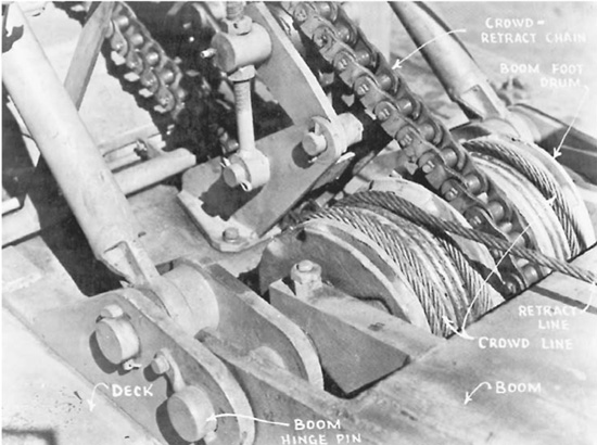
FIGURE 13.47 Front view, boom foot drum.
FIGURE 13.48 Dipper shovel reeving, cable crowd.
Big Stripping Shovel. The big Marion strippers use a special crowding mechanism, shown in Fig. 13.49. The stick is in two pieces, hinged to each other and to a stiff leg pivoted on the deck behind the boom. The boom has a wide center opening, allowing the front stick to work through it without touching.
The rear stick or crowding handle has rack teeth, and is crowded and retracted by shipper shaft pinion gears driven by electric motors mounted in the gantry.
The boom carries hoisting strains only, and therefore can be lighter in construction than if it had to line up and crowd the stick as well.
Bucket Trip. The dump line for the bucket door may be operated by mechanical or electric power.
The trip in Fig. 13.50 is mounted on the end of a live shaft in the deck machinery. A drum rides freely on the shaft and can be connected to it by a brake-type clutch or a ratchet which is held out of engagement by a spring.
The drum contains a spring which keeps a tension on the dump line sufficient to pull in slack when the bucket is retracted. Engaging the clutch or pawl reels in the line with a snap sufficient to pull the latch and allow the door to open.
An electric trip consists of a small starter-type electric motor equipped with an eccentric sheave. Actuating the sheave through a pushbutton switch controlling the motor produces a pull on the cable to release the latch.
The unit may be mounted on the lower boom near the shipper shaft, or on the shovel deck.
FIGURE 13.49 Knee-action crowd.
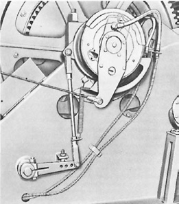
FIGURE 13.50 Hydraulic control dipper trip.
Electrics and Diesel-Electrics. All-electric shovels and draglines normally operate on three-phase alternating-current (ac) power furnished at between 2,000 and 8,000 volts by utilities (high lines) or by generator sets assembled on the job.
Electric units are used to serve in the place of the internal-combustion engine, and of the clutches, brakes, mechanical controls, and to eliminate some of the gears, chains, and cables, so that construction is quite different from that of the diesel-powered rig.
A diesel-electric shovel carries a diesel engine and a generator to supply current to electric motors and controls that perform all operating functions. A part electric machine has diesel power, with mechanical drive to some power trains, and electric to others. Electric swing clutches may be used in a machine that is otherwise all-mechanical.
In excavators used by contractors, electric and diesel-electric drives begin to appear in the 3- and 4-yard (2.3- and 3.1-cu.m) class, and are standard in very large machines.
In the development of electric power for large shovel excavators, Harnischfeger found that what was needed is a system for static, solid-state electronic conversion of pit ac power to dc main power supply, with controlled delivery of this main power for the motion drive motors. They developed the patented Electrotorque Control system, which eliminated the need for the familiar ac-to-dc rotary type of motor-generator set. Also it essentially eliminated inductance, which is the main impediment to quick response from electrical systems. To do this required motion drive motors with much better transient dynamic response characteristics than were then available from any source.
Figure 13.51 shows a forward hoist motor and helical cut teeth of the first of two reductions to hoist rope drum gear. The hoist brake mounts on an involute splined extension of the pinion shaft.
In many ways electricity is an ideal power for excavators. Since it allows packing a lot of power in a small place, motors can be placed so as to eliminate complex gear trains and chain drives; maintenance and fueling of an internal-combustion engine are eliminated, exhaust gas is not a problem indoors or underground, and operation is smooth and quiet. Controls are easy to operate.
But first cost is higher, particularly in small units, and in any size the necessity of being near a power source and of having a cable connection can hamper activities severely. There are also technical problems involved in conveying the heavy current into the revolving frame, and in controlling and distributing it.
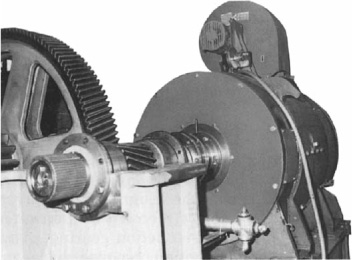
FIGURE 13.51 Electric hoist motor. (Courtesy of P&H Mining Equipment.)
The diesel-electric is independent of outside power, and has the smoothness and some of the simplicity of electric drive. Engine fueling, maintenance, and noise are about the same as with mechanical drive.
Controllers. The main operations of the electric excavator depend on three master controllers at the operator’s station. Two of them, the hoist and crowd-retract in the dipper shovel, or the hoist and drag in the dragline, have hand levers. The swing is operated by a pair of foot pedals.
By means of these, circuits carrying light current can be opened, closed, or “throttled” to regulate flow of current to a desired amount. There are several types of controllers now used in excavators, of which three will be described.
One, the rheostat or resistance type, includes a number of circuits of different resistance, connecting a power source and the generator fields. A rotating switch provides means to close any one of these to permit current to flow through it. The contacts are arranged so that in moving from the Off position, the controller closes the circuit of maximum resistance first, and those of diminishing resistance in succession, until the final full-flow connection is reached.
Ward-Leonard System. Most electric excavators use a drive and control system that makes it possible to control the heavy working current by varying a light current to generator fields. Figure 13.52 indicates schematically the principle of operation, without in any way representing the actual mechanical and electrical layout.
One or more ac motors (one shown) turn a set of three generators, that supply direct current to the hoist, crowd, and swing motors. The output of each generator, and therefore the speed and power of the motor it powers, is regulated by the flow of exciting current through its field coils.
This current, in turn, is regulated by the position of the controller lever at the operator’s station. Thus an easily handled low-voltage small-amperage current is stepped up to regulate the high voltage and very heavy amperage needed to provide the power required at the hoist drum and at the crowd and swing pinions.
The main ac motor turns at full speed whenever it is switched on, but current consumption is light when the generators are not charging and the dc motors are idle.
The swing and crowd-retract generators have means to reverse the direction of current flow. The crowd motor is reversible, and the swing may use either one or two reversible motors geared to individual swing pinions.
The hoist motor is also reversible, so that it lowers by power at a controlled speed, instead of allowing the bucket to drop by gravity. A mechanical clutch (friction or pneumatic) is usually put between it and the drum, adjusted so that there will be slippage to absorb shock if the dipper stops suddenly.
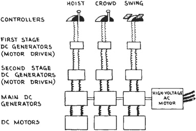
FIGURE 13.52 Block diagram of Double Ward-Leonard system.
A gearshift, or moving of jaw clutches, permits the hoist motor to be used to propel the shovel.
DC is usually selected for motor drive because of its ability to develop high torque when lugged down by heavy loads and to use variable voltage without damage.
The P&H electric shovels of 22 to 56 cubic yard (17 to 43 cu.m) capacity, such as the machine in Fig. 13.8, are representative of a class of excavator that is widely used in pits, quarries, and mines; usually in loading blasted rock and ore into hauling units.
Power Line. The power line is carried overhead, often on portable or temporary poles, to the immediate vicinity of the shovel; then along the ground in a flexible, heavily insulated tail cable to a terminal box in the lower frame.
A ring-type high-voltage collector is located at the base of the vertical propel shaft. This consists of three pairs of rings in an oil-filled moistureproof case. One ring of each pair is stationary and connected to one of the three input wires; the other revolves with the upper frame and is connected to one of three lines going up through a protecting sleeve inside the hollow propel shaft and to the control panel. The rings keep constant contact in any swing position of the shovel.
Power requirement of the 22-yard (17-cu.m) shovel is a minimum 2,000 kilovoltamperes from a high line, or more from a diesel generating set.
Control Panel. The control panel contains the master switches and fuses both for the incoming alternating current and for the dc circuits from main generators to motors; selenium rectifiers that convert ac to dc to operate brakes, dipper trip motor, and main motor fields; and low-voltage ac from the controllers into dc for generator field excitation.
There are also transformers to step down ac voltage for use in the controllers, lights, auxiliary motors, and the crowd-propel circuits. For instance, for the 22-yard (17-cu.m) shovel mentioned above, the transformer for the main armature is 1,500 kilovoltamperes, for the auxiliaries is 250 kilovoltamperes, and for the relays and lighting supply is 45 kilovoltamperes.
The approximate path of current through various parts is indicated in Fig. 13.53, and the operator’s controls are shown in Fig. 13.11 or 13.54 and 13.55.
Motors. The identical crowd and swing dc generators are mounted on the extended shaft of the main motor. They are driven at constant speed, and output is varied from zero to maximum by the current supplied to the field coils.
The reversible crowd-retract motor, is mounted on the boom just below the shipper shaft. Crowding or retracting of the straddle-type sticks is accomplished through a worm, worm wheel, and a set of spur gears, the combination of which links the crowd motor to the gear racks on the underside of the dipper sticks. The motor is cooled by filtered air from a blower.
Brakes. Each motor or gear train is equipped with a powerful brake that is held out of engagement by an electromagnet, so that if power is cut off, either deliberately or accidentally, the unit “freezes.” Current is shut off and brakes are applied by pushbuttons at the operator’s station.
The pushbutton or automatic control is used to hold the bucket and sometimes the swing while waiting for arrival of trucks, or for other developments. The automatic application protects the machine and its surroundings against damage in the event of power failure.
Ventilation. A blower in the top of the cab draws in filtered air and maintains the cab above atmospheric pressure. Some air leaks out, but most of it is drawn out by blowers, one to each motor, that prevent overheating by keeping a current of air moving through them.
The main filter keeps the air clean so that abrasive dust is not blown into the motors.
There is a door between the operator’s station and the main cab, to use or avoid the airflow, as desired. If this door is open, the windows must be closed.
FIGURE 13.53 Block diagram of electrical layout.
Propel. Current from the crowd generator can be diverted from the crowd motor to the propel motor by flipping a switch on the crowd lever (controller handle). No gears or clutches are involved in this instantaneous one-finger shift. The automatic brake locks the crowd while current is used for propelling.
The propel motor is mounted vertically on the deck, and is permanently geared to the vertical propel shaft. This drives a horizontal shaft, which turns the live axles extending across the rear of the travel unit.
The propel shaft brake holds the machine while digging, and at any time that it is not disengaged by current activating the propel motor. The fact that the power train is permanently geared to one axle prevents any possibility of a runaway—a good consideration in an excavator of such weight, up to 1400 tons (1,270 metric tones).
FIGURE 13.54 Operator’s station.
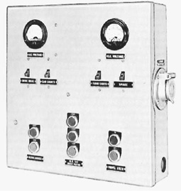
FIGURE 13.55 Operator’s switch panel.
The techniques used for operating a front shovel, especially those for crowding the bucket into a bank, cannot be described well enough to be helpful to the reader. See Fig. 13.8. The movements and feel for the work of the machine have to be experienced to understand them. Therefore, it is recommended the inexperienced person seek the opportunity to work with an experienced operator to learn techniques.
There are some maintenance problems in dealing with the cables that will be described for the benefit of an inexperienced operator or manager of equipment maintenance. These will be discussed in the following paragraphs.
Tangled Cable. If the hoist clutch and brake are released when the bucket is in the air, it will fall, unwinding the hoist cable from the drum rapidly. When the bucket strikes the ground, it will stop pulling on the cable but the drum will continue to revolve with its own momentum, pushing the cable. This will result in the cable’s leaving the drum and looping itself all over the machinery, or the drum’s revolving inside the wraps of cable, thus loosening all of them back to the anchor, or both. If the hoist clutch is engaged and the cable wound back onto the drum, the wraps will cross each other and tangle. If a heavy load is picked up by the cable in this condition, it will be strained, deformed, or crushed. In addition to having its life shortened it will then be difficult to spool onto the drum smoothly unless under enough load to pull its kinks straight as they come in.
The easiest way to straighten out this mess is to manipulate the bucket so that it will pull most of the cable away from the drum. It is first necessary to engage the hoist clutch and reel in the disordered cable, then hoist the bucket, dumping it first if loaded. The bucket may then be crowded all the way out and rested on the ground, dropped in a hole, or pulled back close to the tracks. There will now be only a few wraps of cable on the drum, which can be straightened out with the gloved hand, or gently with a screwdriver and a ball peen hammer. The engine clutch should be disconnected before handling the cable, as an inequality in the hoist clutch might cause it to tighten the cable with a jerk even while disengaged. Leather-palm gloves should be worn because even a preformed cable may have projecting broken wires that cut like needles.
If the cable has been loaded at all while tangled, it should be put under heavy tension while fully extended to straighten out kinks.
Tangling the cable in this manner is one of the principal bugaboos for beginners. It can be avoided almost entirely by riding the brakes, that is, by keeping a light pressure on the foot brakes at all times—not enough to stop the drum from being turned, but sufficient to stop free spinning. This is bad operation as it gives the shovel a constant drag to overcome, increases lining wear, and heats the drums. However, none of these drawbacks are serious enough to counterbalance the wasted time and labor, the loss of confidence, and the damage to the cable resulting from tangles. The new operator who develops good coordination with the controls can then train himself or herself to release the brakes fully instead of partially.
The crowd-retract cables should not tangle unless loose. They are straightened by prying with a screwdriver, and working the stick back and forth.
Cable Breaks. Shovel cables are subject to shock, heavy loads, sharp bending, rapid motion, and exposure to weather; and drag cables may be exposed to friction with earth and rock. They may last a few hours or years, but sooner or later they will break unless replaced. If the break occurs during work, time is lost until another cable can be obtained and installed. If the break occurs at the wrong time, it may cause injury or death to personnel and damage to property.
A cable that is abused, is too small for its work, or is of poor quality or defective may break suddenly before showing any signs of wear. Usually, however, a wire rope will not break until weakened, and inspection will show thinned and broken wires on its surface. Such a cable may last a long time, but it is good operation to change it during maintenance time in order to eliminate work stoppage and possible damage when it fails.
Cables often break one strand at a time, giving the operator warning before parting completely. However, the fact that 50 cables may break in this manner is no proof that the fifty-first will not snap suddenly, either under load or reaction from load.
FIGURE 13.56 Dipper hoist and trip lines.
Torque converter drive prolongs rope life and reduces the likelihood of sudden failure.
Replacing Cable. For safety’s sake, the engine should be stopped before a cable is replaced. Some clutches may jerk a line even when they are disengaged, or a helper or a bystander might accidentally lean on a lever at just the wrong time. Drums may be turned and cable reeled in during work by using the starter, or by starting the engine, running it while necessary, and then shutting it off again.
A line that is being replaced is usually partially or wholly in place. If the machine is an unfamiliar one, it is great importance to memorize its exact layout. If a service manual is on hand, the diagram should be checked to make sure it is both right and understandable. If there is no diagram, a rough sketch may be made as a memory help.
It is very embarrassing to pull a cable out and then not remember how it was reeved. Fortunately, shovels are less complicated in this way than scrapers.
A typical hoist line reeving is shown in Fig. 13.56. The line runs from the hoist drum on the shovel deck over a boom point sheave, around the padlock or bucket sheave, over the other boom point sheave, and to an anchor on the boom.
Any part of the old line that is still wound on the drum is stripped off by pulling with gloved hands, with the engine shut off and the hoist brake and clutch disengaged. The old cable should be coiled and tied securely to avoid danger.
Most cable-to-drum anchors are of the wedge type, Fig. 13.57, that can be loosened by placing a driving punch against the small flat end and hammering until the wedge is loose. This will release the cable, which can then be pulled out of the socket with a pry bar or a screwdriver. The other anchor is reached by climbing up the boom or a ladder, or by standing in the raised bucket of a tractor loader, and it is loosened in the same manner.
The new cable, cut to proper length ahead of time or by measuring the old line, is drawn over the proper boom point sheave and down to the hoist drum. The end is pushed through the small end of the anchor socket and bent back into a loop, in which the wedge is placed. The slack is pulled back through the small end by hand, drawing the wedge into the socket. It is forced in by hammer blows, just enough to hold it in place until tension on the cable seats it firmly.
The drum is turned to reel in the line until the other end is near the bucket sheave. That end is then reeved through this sheave, over the empty boom point sheave, and is anchored to the boom. Putting the cable on the drum and then drawing it off in this manner is a precaution against kinking it.
FIGURE 13.57 Wedge anchor to drum.
With the line fastened at both ends, the engine is started and idled, and the hoist clutch is engaged to wind the slack cable onto the drum. It should wrap smoothly, with each loop lying against the previous one. A person working alone will guide it from near the drum with a gloved hand; a helper can pull the slack down to the bucket sheave and keep light tension on the line from there. Some resistance or back pull helps to make it wind snugly.
The anchor clamps are tightened by running the empty bucket down and out until the cable is stripped from the drum, and stopping it abruptly with the brake. This should be done two or three times. It is important to keep the cable from running slack for the first hour or two of operation, as it is most likely to cross loops on the drum before it is broken in.
Badly worn or damaged cables should be replaced in nonworking time before they break. Downtime on a shovel loading a string of trucks costs much more than the cable and the labor of changing it.
Sometimes a cable is cut to the wrong length by mistake, or it is convenient to use a precut line of slightly different length. One that is too long may be hard to fasten securely to the drum, as the extra wraps make it hard to put enough tension on the anchor to seat the wedge. If the drum is exactly the right size to hold the correct length of line, the extra will start a second layer, causing severe wear at the point where it snaps over.
If the drum is small enough that there is overlap with standard length line, or wide enough to take the extra on the first layer, this causes no problem.
A hoist line that is too short may limit bucket movement, and is likely to cause a damaging jolt by the anchor stopping it if it is run out too far. An instruction book may specify a cable that is too short for comfortable operation.
The hoist is the most frequently broken line on a dipper shovel. Under severe conditions it may break several times a week, but this much trouble usually indicates overloading or other abuse. A too-large cable will be damaged by pinching in sheaves; one that is too small breaks from lack of strength.
Procedure is similar for a boom cable, except that the boom must be rested on the bucket before taking off the old cable, and reeving between the A-frame or gantry and the boom point is usually a four-part line that requires more care in getting it on right. See Fig. 13.58.
In order to change a crowd or retract cable, the turnbuckle fastening the retract to the bucket must be loosened. The new cable or cables are cut carefully to proper length, and installed to be snug with the turnbuckle loose. Tightening will put it under proper tension.
Safety Precautions. An operator should lower the bucket to the ground before leaving the machine, as the brakes may lose their grip as they cool and let the bucket down, gradually or with a rush. There is also the possibility of a would-be operator accidentally releasing the hoist brake while an admiring friend stands under the bucket.
Workers and spectators should always keep beyond the farthest reach of the shovel, if possible, but they seldom do.
The engine clutch should always be disengaged during maintenance work, except when it is necessary to move parts for access.
Booming Up and Down. The boom is normally held in a fixed position during digging. However, lowering the boom enables the bucket to dig deeper and farther away, and raising it permits a higher dump point. If desired, the boom latch may be locked out of engagement, the boom lowered to dig, raised during the swing to dump, and lowered again on the swing back. This uses extra power to lift the boom and may slow the digging cycle, but often simplifies the work. It is only possible with a live boom.
Booms should always be lowered slowly and stopped with the brake, not the ratchet.
Applications. The front shovel is a good machine for truck loading. See Fig. 13.8. It is accurate because of the three-way control of the bucket and the ability to dump in any position. It is fast because only a small part of its weight—the stick and bucket—is involved in the digging motion, and because of its ability to dig in any spot it can reach with minimum waste motion when approaching and leaving the cut.
The dipper is also the attachment for hard, heavy digging—hardpan, boulders, ledge, and blasted rock. The weight of the boom, backed to a varying extent by the weight of the shovel itself, holds the bucket to its work. The effective cutting angle of the teeth in a bank, aided by the variable direction of pressure provided by the hoist and crowd, enables it to cut highly resistant material and to break up cracked and fissured rock formations. The shape of the bucket enables it to pick up objects much larger than itself without chaining. Larger shovels are increasingly effective at this type of work.
However, it is necessary that the shovel be able to move into its work constantly in order to retain its effectiveness. Solid rock projecting from the pit floor will prevent getting at the bank unless ramps are built over the rock, or bulldozers used to push the bank to the shovel. In digging below the tracks, the downslope should not be much over 20 percent if the machine is to follow the work. If it is to stand at the edge and dig, it can cut down steeply 5 to 7 feet (1.5 to 2.1 m), but is limited as to width of cut, and unless digging against a bank may push away about as much material as it picks up. Refer to Fig. 13.22.
A shovel does not work efficiently at its maximum reach as it loses in lift, in ability to fill the bucket in a short sweep, in tooth angle, and in accuracy of control. Good digging practice is to keep the shovel close to the work and trucks down at its level for easy, accurate loading. Special situations often arise, however, where every inch of reach must be utilized.

FIGURE 13.58 Dipper boom reeving.
Swing speeds are quite variable, ranging from 4 to 5½ revolutions per minute. This difference is not very important, as the gain in speed usually means a loss of power. A slow-swinging shovel may swing from digging to close dumping position more quickly than a fast-swinging one of the same power because of more rapid acceleration, but will be slower on a long swing.
Operating Suggestions. The following is a list of suggestions for efficient dipper stick operation:
1. Keep bucket teeth sharp and built up to proper size.
2. Do not crowd bucket so deep into the bank that it slows the hoist.
3. Pull bucket out of the bank as soon as it is full.
4. Keep close to the bank unless it is likely to slide.
5. If bank is very hard, or material needs mixing, make passes in it with bucket door open.
6. Place shovel so that the drive chains are away from the digging.
7. Spot trucks as close to digging as safety permits to save swing time. See Fig.13.59.
8. Spot trucks on both sides if possible to save waiting time while trucks move.
9. Spot trucks so that they line up with arc of swing, or back them directly toward the shovel.
10. Do not swing over truck cab if you can avoid it.
11. Move up while waiting for trucks.
12. In mud, load driest material in bottom of truck, sticky stuff on top, for easier dumping.
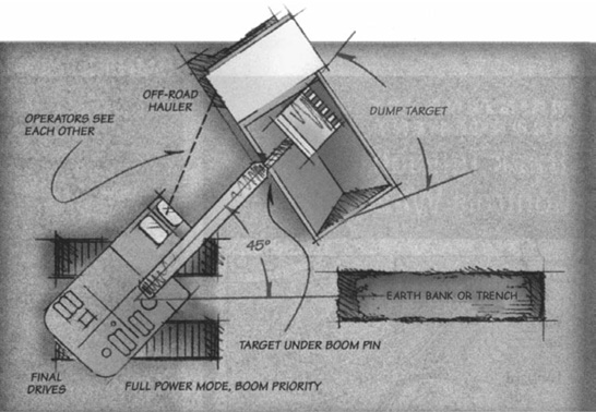
FIGURE 13.59 Best truck position for loading from shovel. The ideal setup for loading spoil in trucks puts haul units close to the cut where bucket swing is short and through the end gate. Dump as the boom swings, smoothly filling the truck body and unloading the excavator before it must reverse the swing direction. Place dump targets just off the end of the boom, so that extending the stick to keep the bucket over the truck bed will also position the stick to begin the next cut. You’ll seldom see all of these conditions on a trenching site, but using any of these elements will boost productivity.
13. Do not let tracks sink deep in ground—bury mud with dry fill or use poles or platforms.
14. Work smoothly—slamming and jerking are hard on machine and operator.
Dredges. Partial-swing cable shovels in large sizes are still used as dredges. They are mounted on barges or ships, for underwater work in which bottom hardness, spoil disposal, or other conditions are unsuitable for the hydraulic dredges described in the next chapter.
Figure 13.60 shows a large dipper dredge and Fig. 13.61 a grapple dredge. Loading is done on barges moored at either side, or on shore if it is close enough. Occasionally the spoil is dumped back in the water at the side.
Barges are towed to the job and maneuvered on it by winch lines attached to anchors. Pointed steel pipes, called spuds, are driven into the bottom and used as braces against digging thrust, wind, and waves.
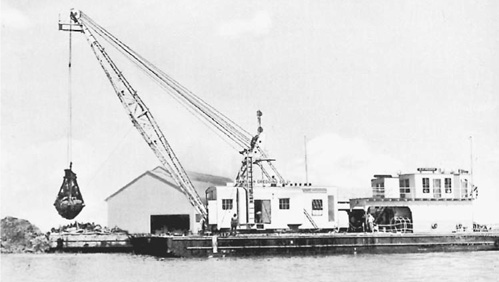
Dipper dredges are suited to deepening harbors and channels where the space is too restricted or the bottom too hard or coarse for hydraulic dredges. They are also used for digging canals through swamps where there is too much standing water to permit the use of land machinery.
Grapple dredges are best suited to work at depths beyond the economic limit of other types, and for cleaning up loose rock. Hydraulic dredges will be discussed in the next chapter.
Depth Gauge. A backhoe of any type may have a built-in device by which the operator can check the depth of excavation from the control station.
The Accu-Depth, Figs. 13.62 and 13.63, is made up of a sensor or transmitter fastened to the stick near the bucket, a fluid-filled transmitter tube, and an indicating head or gauge.
To set it for a reading, the operator places the bucket on a reference point, depresses a valve button on the head, then rotates its dial until zero lines up with a pointer. The operator then places the bucket, in the same position, on the bottom of the trench, and opens the indicator valve again. The pointer swings to indicate the vertical distance (depth) of the second position (ditch bottom) below the reference level.
The fluid in the system is supported by atmospheric pressure. Its weight at the sensor increases in direct proportion to the vertical distance between sensor and head, creating a vacuum whose variation moves the pointer. Maximum working depth is 28 to 30 feet (8.5 to 9.1 m), but within this range, error is said to be less than ½ percent.
The reference point may be the ground surface beside the ditch, a section of completed bottom, a grade stake, or a stringline.
Other methods of checking depth are discussed under Operation.
Clamshell. Many hydraulic excavators may be fitted with a clamshell bucket, which replaces the hoe bucket or immobilizes it. The clam jaws are opened and closed by a two-way cylinder.
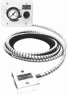
FIGURE 13.63 Accu-Depth installation. (Courtesy of Amtek/U.S. Gauge.)
This may be mounted horizontally across them, or be part of an attaching stick vertically above them. Closing power is supplied from the hoe bucket circuit.
The clam is usually attached to the end of the hoe stick by a universal mounting, which allows it to hang straight regardless of stick position or machine slope. There may be part or full rotation, controlled by the operator. See Fig. 13.64.
Attachment may be direct to the mounting, or through one or more vertical extension rods. Extensions provide greater digging depth but less dumping height. Maximum length is limited by dumping requirements, or by clearance needed to lift the bucket out of the ground.
This type of clamshell is a powerful digging tool, in which down pressure may be added to jaw closing power. However, its applications are limited by restricted lift as compared with a cable-operated clamshell, and it is slower than a hoe. Some additional lift may be obtained by using a power-controlled hinge in the boom gooseneck angle.
Demolition Head. A demolition head, operated either by the excavator’s hydraulics or by a separate air compressor, may be substituted for the bucket. This may be used for breaking boulders, weak bedrock, pavement, and structures, and driving trench bank supports. These devices are described in Chap. 19.
Even with a standard bucket, a big hydraulic hoe is a powerful demolition tool because of its fairly long, high reach, with ability to both push and pull forcefully.
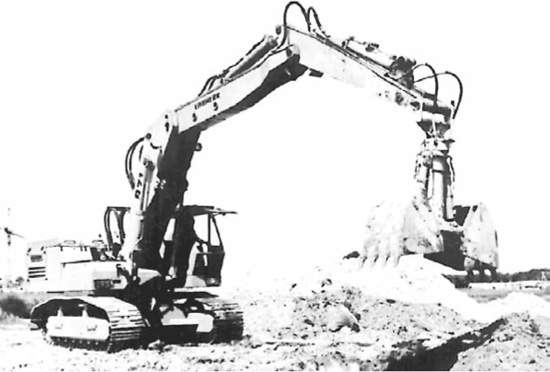
FIGURE 13.64 Clamshell on double-hinged boom. (Courtesy of Liebherr-America.)
Some aspects of backhoe operation were discussed in Chaps. 4 and 5, in connection with basement excavations and ditches.
Operation of a full-revolving hydraulic excavator or backhoe is under complete control because of two-way power and “wrist-action” flexibility in the digging and dumping angle of the bucket.
Effect of Controls. In one control system, the boom hoist lever actuates the cylinder(s) that supports the boom. Moving the lever forward forces the boom down, pulling it back raises the boom.
It may be unwise to move this lever all the way forward when the boom is raised, as in some machines it will allow the boom (and the whole attachment) to fall with dangerous speed and force.
There may be a finger button or some other device to divert fluid from the swing circuit to the boom circuit, to raise it more rapidly from a deep excavation.
Tilting the stick (crowd) pedal forward retracts the stick cylinder, pulling the top of the stick back and swinging the bucket forward. Back-tilting the pedal reverses these motions, crowding the bucket inward toward the cab.
Since the stick is fastened to the end of the boom, its position in space at any time depends on both the boom and the stick cylinders.
The bucket pedal, when tilted forward, causes the bucket cutting edge to move out, opening and dumping the bucket. When tilted back, it brings the edge inward, closing or curling the bucket.
The swing lever rotates the upper works to the left (counterclockwise) when pushed forward, and to the right when pulled back. In most machines, an automatic brake stops the swing smoothly when the lever is centered. There should be a lock-down pedal brake also, to lock the swing during travel.
In this example, the travel or propel lever moves the machine in the same direction it is moved. The right-hand steering lever controls the clutch and brake for a right turn, the left lever is for the left controls.
All these controls are (or should be) the metering type that can be partially opened to obtain fractional speed, for performing delicate operations slowly without reducing engine speed. But accuracy of response of part-open valves is quite variable.
Also, all levers except possibly the travel control are spring-loaded to return to neutral (center), and automatically lock their unit when centered by holding fluid in cylinders. In motors, there is usually a brake that is applied by springs in neutral, and released automatically by fluid pressure.
Other Systems. Probably no two makes of excavator have exactly the same arrangement of levers and pedals. The type that is most conspicuously different from the example described is the so-called joysticks for attachment control, and separate hydraulic drive to the two tracks. See Figs. 13.26 and 13.27.
One joystick controls both the stick and the swing. The stick valve is operated by the front-to-back motion of the stick, the swing by its side-to-side movement. The other stick moves forward and back to move the boom in the same directions, and moves left to curl the bucket and right to dump it. The two motions do not interfere with each other, and the valves operate in the same manner as when responding to individual levers or pedals.
Hydrostatic propel can be controlled in several different ways. In this example there are two foot pedals. Pushing the left one, accelerator fashion, moves the machine back; the other one moves it forward. Speed is regulated by pressure on the pedal, from zero in full-up position to full speed when depressed to the floor.
A single steering lever is moved to the right for right turns, to the left for left. There are three stages. In the first, nearest center, one track is driven faster than the other. The next locks one track while drive (regulated by the foot pedal) is continued to the other. The third stage, reached by pushing the lever past a bumper spring, causes the tracks to rotate oppositely, for a spin or spot turn.
Attachment Motions. Assume that the excavator is parked with bucket drawn in under the boom, as in Fig. 13.65, and that it is properly located on the centerline of a proposed ditch.
The bucket is freed from the ground by raising the boom, and moved toward digging position by extending the stick. The two movements are made at the same time. Until the stick reaches a vertical position, its arc of swing is down, and must be compensated by continued raising of the boom.
FIGURE 13.65 Bucket tucked in.
When the stick has passed the vertical position, its continued motion will take it in an upward arc. If it is to be kept near the ground, the boom is now lowered as the stick is moved outward.
When the stick is extended three-fourths or seven-eighths of maximum reach, the bucket is opened until the floor is about vertical (teeth straight down). It is then lowered (not dropped) to the ground by pushing the boom lever forward.
The stick may now be crowded inward, while the bucket is rotated gradually toward a half-closed or digging position. At the same time the boom is raised slowly, so that the downward arc of stick motion will not bury the bucket too deeply.
The bucket curl is adjusted for best penetration and filling, which is likely to be at an angle of 15° to 45° to the surface being penetrated. Except when finishing off, the bucket should usually be filled in as short a digging pass as is feasible, without slowing the engine or dragging the shovel. Long passes take longer, and usually wear the bucket more.
Digging angle may be varied during digging. There should always be at least a slight angle, so that the bucket floor will not be dragged on undug dirt. Such dragging consumes power and causes excessive wear. Small changes in angle help the teeth in “hunting” for easiest penetration.
If the digging pass continues under the boom point, the bucket path will curve upward, and the boom will require lowering instead of raising if it is to be kept level.
To guide the operator, a device like Spectra Precision’s BucketPro (see Fig. 13.66) would be very helpful. A control screen next to the operator’s seat shows the current position of the bucket relative to the bottom of the excavation to be dug. The final depth of the excavation can be set on the screen.
Down pressure can be applied to the bucket to improve penetration, by not raising the boom or by pushing it down, depending on bucket position.
When the bucket is full, it should be closed or curled, the crowd motion should then be stopped, and the bucket lifted out of the ditch by pulling back the boom hoist lever. See Fig. 13.67.
As soon as it is clear of the ground, it is swung to the side, and dumped by pushing the bucket lever. Generally, height is figured so that the teeth will just clear the pile. A higher position wastes time in excess hoisting, a lower one exposes bucket and stick to impact and twist.
However, if the pile will be big enough to threaten to slip into the excavation, the dump may be made in the pile, so that opening the bucket and extending the stick will push soil away, to make room for more. The swing should be fully stopped before entering the pile, to avoid twisting strains.
The bucket is swung back to the excavation as soon as it is dumped and clear of the pile. During the swing it is brought back to digging position, in both degree of curl and in-and-out position on the stick control. It is lowered to the ground, and pulled in to refill.
To avoid building a pile of earth at the near edge of the excavation, always rotate the bucket toward a closed position, before bringing it out of the ground.
Finishing. The ditch is dug in a series of slices or chunks, down to the bottom. Depth may be measured by the operator or a helper. But if the trench is being dug to a fixed depth below ground surface, it is more convenient to put a mark on the stick that, when it is vertical and the bucket is flat on the ground, will indicate the correct depth. Or a device like the Accu-Depth described previously can be helpful.
The far wall can be trimmed by forcing down the bucket with the floor vertical, keeping it vertical as it goes down by curling out just enough to compensate for the inward curve of its descent. When the bottom is reached, the bucket may be pulled in with a slight lift until clear of the back wall, then closed into its load.
FIGURE 13.66 Spectra Precision’s depth control device. With grade checking in the cab, the operator never loses the “feel” for grade or obstacles.
Pipe may be set in the trench under laser control, close to the digging. A mark may then be made on the back of the bucket, to line up with the beam at correct depth. This provides absolutely accurate control.
The ditch floor is trimmed by keeping the bucket curled so that its bottom is either at right angles to the floor, or flat on it, and crowding it in with the stick while moving the boom up and then down to keep the bucket path level. Curl will need to be adjusted as the stick swings on its hinge.
These two bucket positions share the advantage of having no suck (tendency to dig in). Teeth-down leaves soil looser and may be harder to keep level.
To trim the near wall (this is usually not necessary), pull the bucket to it along the ditch bottom, with its floor flat. Curl it up into the bank, then raise it with the boom hoist.
The boom will tend to pull it away, so crowd the stick in just enough to compensate. This will increase the curl of the bucket, so keep extending (flattening) it to keep the teeth in cutting position.
After practice, you can balance these three movements so that the bucket will come straight up on the desired line, at a good cutting angle.
Boulders. To dislodge a boulder, dig down on both its far side and its near side. Then place the bucket just beyond it, with the floor sloping at a steep angle. Apply boom down pressure and move the bucket lever back and forth rapidly.
When the teeth have penetrated to the underside, crowd and curl the bucket. Crowding keeps it close to the rock, and curling exerts great breakout force. See Fig. 13.68.
FIGURE 13.67 Bringing up a full bucket.
A boulder too large to lift in the bucket may be rolled out by ramping the near side, then backing away, pulling and rolling it up the slope.
Stalling. The bucket may be stalled by digging resistance, either alone or in combination with a full bucket. Immediate action must be taken, either to reduce the resistance or to cut off the power. Otherwise, oil will overheat and parts will be strained.
Another effect of too much resistance is a tendency to drag the machine toward the bucket. This problem will be discussed in connection with tractor-mounted hoes, in which it is more serious.
Chopping. Small quantities or layers of frozen ground, soft rock, or other resistant material may be loosened by lifting the attachment and dropping it, teeth down, a technique known as chopping. It is hard on the machine, and should be done only when absolutely necessary.
To avoid serious damage, be sure that no cylinders are at the ends of their strokes. Lack of cushioning by the hydraulic system in such positions causes more severe shock to the parts.
Combining crowd and down pressure with wiggling of the bucket control often gives more effective penetration than chopping does.
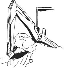
FIGURE 13.68 Dragging up a boulder.
Undercutting Pipe. To undercut a pipe, dig on both the far and near sides, keeping at least a few inches (centimeters) away from it. Go 1 foot (0.3 m) or preferably 2 feet (0.6 m) below the pipe, then undercut with a flat bucket from the far side, and a widely opened one from the near side.
Temporary Support. When making a wide excavation in sandy soil, or above a soft, muddy subsoil, it might be advisable to rest the front of the tracks on a platform, plank or pole, to avoid digging close to the tracks.
Applications. The hydraulic full-revolving backhoe is efficient at truck loading. Its typical cycle, digging at moderate depths and loading trucks (or piling) at its own level, is slower than that of a front shovel working in a bank, but is usually faster than a front-end loader. It varies from 20 to 40 seconds or more.
The cycle may be shortened by at least 25 percent if trucks can be spotted in the pit for loading. See Fig. 13.59. Time in raising the bucket to the surface is saved, and swing can usually be made shorter.
In addition to typical backhoe operations such as ditching, and digging basements and sunken pits, these machines are valuable for mud excavation. They may use platform supports, described in Chap. 3, or depend on their own tracks, either standard or extrawide, for support. See Fig. 13.69.
In such work, they have a great advantage in their ability to apply force to the bucket to pull, push, or raise themselves out of trouble.
A hydraulic hoe attachment similar to that described for revolving excavators can be mounted on the back of a wheel tractor, a crawler tractor, a drag trencher, or a truck. A two-wheel-drive tractor equipped with a front loader is the standard type of carrier.
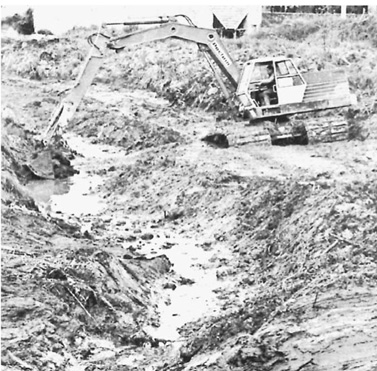
FIGURE 13.69 Wide-track hoe working in mud.
FIGURE 13.70 Quick-detachable hoe. (Courtesy of Ware Machine Works.)
It is usual to install permanent mounting brackets on the tractor, then use pins, hooks, and/or tie bars for more or less quick installation and removal of the hoe unit. The quick-detachable model in Fig. 13.70 is designed for four-wheel-drive units, and includes a seat. On two-wheel-drive units, the tractor seat may swivel to give access to the hoe.
There are also integral units, in which the tractor has mountings for both hoe and loader built into its own frame. These units are almost always smaller and lighter than full-revolving rigs, but they are nevertheless powerful and capable machines.
Boom, stick, and bucket are similar to those on the larger machines, but there are many differences in detail.
Swing. The boom and associated digging parts are mounted on a small turntable that swings through only about half a circle, 175° to 210° on different models. Full swing is not practical because the tractor is in the way.
The pivot is usually a pair of pins, upper and lower. Power is from a pair of hydraulic cylinders based on the nonrevolving frame. The rods may be connected to brackets, or to opposite ends of a roller chain meshing with a sprocket on the rotating section. A partial-swing vane motor may replace the pistons.
Swing is usually very fast, as there is no heavy deck full of machinery to move. Acceleration and deceleration are rapid, allowing 90° swings to be completed in as little as 3 seconds. Action is likely to be jerky.
Partial swing causes little difficulty in straight, open work, like digging a ditch across a field. But it creates serious problems with complicated jobs.
Stabilizers. A pair of heavy stabilizer arms or outriggers is hinged to the sides of the turntable base. They are raised and lowered by two-way cylinders.
Cleated shoes on their outer ends are forced down against or into the ground while digging, to increase stability against tipping, and against being dragged by the bucket.
Hydraulics. The pump and reservoir are usually in the tractor. The most convenient arrangement is to have one pump for the backhoe and another for the loader. It is more usual to have one pump, and a diversion valve to route the flow to whichever unit is in use.
A backhoe and loader are not used for digging at the same time, but it is frequently necessary to make position adjustments in one while working with the other.
A pair of hoses with quick-detachable couplings brings the fluid to the valve bank in the hoe.
There are six operating valves, and usually six levers. But four functions may be performed by two joystick levers, that move to the sides as well as back and forth.
Figure 13.71 shows a standard type of control with a usual but not necessarily standard arrangement of functions. There are also universal controls, whose levers actuate cables that can be switched from one valve to another, so that the operator can make up her or his own pattern. See Fig. 13.72.
FIGURE 13.71 Tractor hoe controls.
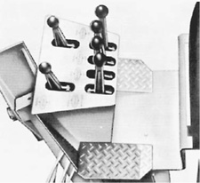
FIGURE 13.72 Universal controls. (Courtesy of Ware Machine Works.)
Pressure in different machines is variable, and is not always stated in specifications. Many models range from 2,000 to 3,000 pounds per square inch (140 to 210 kg per sq.cm), with flow 15 to 35 gallons (57 to 132 liters) per minute.
Buckets. Buckets are similar in construction and linkage to those of the big machines, but differ in size. The smallest standard models seem to be 12 inches (0.3 m) wide, with a capa -city of 3 cubic feet (0.08 cu.m); the largest, 36 inches (0.91 m) wide with more than ½-yard (0.38-cu.m) capacity. In addition, there are specialty buckets on miniature hoes as narrow as 6 inches (15 cm).
Even a standard-size tractor hoe may replace the bucket with a ripper tooth as narrow as 3 inches (7.6 cm). This is primarily designed for penetrating very hard, frozen, or bouldery soil, but it may dig a slot for cable or conduit installation.
Applications. The tractor-mounted hoe is a small, powerful, and fairly economical package. It can be driven between jobs, or carried easily on a light trailer.
As a ditch digger, it can work in places that are difficult or impossible for larger machines, cross lawns without damage (except under unusually soft conditions), make narrow ditches, and show a high production rate.
It does not trench as fast as the continuous-type ditchers discussed in the next chapter, but it can handle special situations that are difficult for them, can work in rocky soil, and can handle oversize pieces.
It is also a handy utility tool. It can dig out stumps and boulders so big that it cannot possibly lift them, can load trucks with either the hoe or the loader end in emergencies, and can serve as a light-duty (but very jerky) crane.
The boom, stick, and bucket are similar in action to full-swing attachments. Differences in operation include managing the tractor as a travel unit and counterweight, use of stabilizers, arranging work so that it can be done with limited swing, and doing heavy digging with a light machine.
Positioning for Digging. The tractor is driven to the work spot, and maneuvered so that it is centered on the centerline of a ditch, the rear wheels toward the starting point, and about ¾ of the hoe’s maximum reach from it.
The operator centers the steering wheel, puts the tractor in neutral, and locks its brakes. If one hydraulic pump supplies both loader and backhoe, the operator sets a diversion valve to deliver flow to the hoe. If there are separate circuits, he or she lowers the loader bucket to the ground.
The bucket will hold the tractor most effectively if it is put in fully dumped position, and forced down against the ground. See Fig. 13.73.
The operator then flips the seat over or swings it around, and sits rearward on the tractor, facing the hoe and its controls. In the terminology accepted by the trade, the operator is still facing forward, and hoe motions are described accordingly.
Stabilizers. The two outside controls are used to push the stabilizers outward and downward, pressing them firmly against the ground so as to take just a little weight off the tractor’s tires.
If the ground is uneven, one is extended farther than the other, to make similar pressure on each side. If the ground slopes to the side, the low one is pushed down harder, to reduce or eliminate tractor tip.
Occasionally, you may wish to put a block under the stabilizer on the low side, or level the ground by some superficial digging.
The standard stabilizer shoe has a ridge or cleat on its undersurface, to penetrate and grip the ground. This is likely to tear up a lawn, not so much from original penetration as from dragging and twisting during digging. Very rarely, you may prefer to try digging without setting stabilizers, for this reason.
On soft ground, a plank may be placed to support the stabilizers.
Digging. Digging motions are the same as those described earlier for the full-revolving excavator. However, this machine is probably very much lighter in proportion to digging power, and is more likely to be dragged into the work.
This dragging occurs as you pull or crowd the bucket inward against digging resistance. It is strongest at ground level, and reduces somewhat with depth.
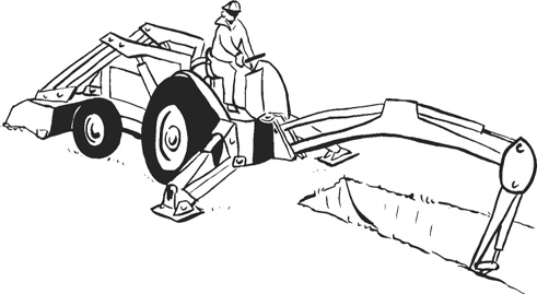
FIGURE 13.73 A dumped loader bucket helps stability.
Cutting a thin slice generates less pull than a thick one, but it takes longer and wears the bucket more. Rapid, small changes in bucket angle as it is brought in reduces resistance.
Curling or closing the bucket provides powerful digging and breakout force at the bucket teeth, with little or no pull on the tractor. See Fig. 13.74.
Starting a deep cut, then curling the bucket as soon as resistance builds up, will usually provide good digging with little dragging.
In general, you try to dig for production, but lighten the cut every time you feel a drag-the-tractor force developing. The reaction is a split-second one, which is difficult at first but soon becomes practically automatic.
Moving. To move when a section of digging is finished, the stabilizers (and the loader bucket if it is down) are raised. The bucket is placed on the ditch bottom with its floor at a slight angle, with the stick almost vertical, but leaning slightly toward the tractor.
Pushing the hoist and crowd levers slowly forward will now lift the back of the tractor off the ground, and roll it forward on its front wheels. If it does not go far enough, the maneuver is repeated. Then the stabilizers are put down, and digging is resumed.
The tractor may be moved to the side in somewhat the same manner. The bucket is curled halfway, placed in the ditch a little forward (away from the tractor) of the boom point, and forced down by the boom cylinder until the rear (big) wheels are clear of the ground. The hoe is then swung until the tractor is in the desired position. See Fig. 13.75. Then it is lowered, and the stabilizers are set for digging.
Stability. The total weight of a tractor-hoe, including its loader, is much smaller in proportion to digging power than that of a full-revolving machine. Stability is therefore more of a problem.
Down pressure on the bucket tends to lift the rear wheels off the ground. Upward pull lifts the front wheels. Rearward (toward the tractor) pull may either dig the dirt or drag the tractor.
Tractor weight must be increased to its maximum by putting water and calcium chloride, or perhaps mineral dust, in all four tires. The loader bucket may be filled with dirt, or piled with rocks or other heavy objects. It may be held in the air for counterbalance (and for convenience in moving), or may rest on the ground for resistance to dragging.
Stabilizers should be put down far enough to take a little of the weight off the rear tires, as will be indicated by a slight change in shape at the bottom. Tires must never be lifted clear of the ground, or even so that most of the weight is off them, except one side in leveling on a slope. On ordinary ground, a ridge on each stabilizer pad sinks all the way in.
Rear wheels (larger ones in figures shown) are locked by the tractor brakes.
Even with these precautions, weight and grip on the ground are small in proportion to the digging forces—crowd and curl—which may be more than 6 tons (5,400 kg). The operator must limit the force he exerts to the ability of the machine to keep its position.
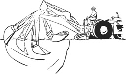
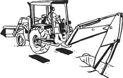
FIGURE 13.75 The hoe moves the tractor.
Digging without pulling the tractor may be the hardest thing for the beginner to learn, as was discussed earlier, but it ordinarily offers few problems to the experienced operator. It is largely a matter of learning manipulation of the bucket to obtain penetration without excessive pull.
When the tractor is dragged toward the digging, it is usually necessary to reposition it with the bucket. If the movement has not been straight, it may be necessary to drive the tractor to get it in proper alignment.
Stability against tipping is ordinarily not a major problem in digging. But if the tractor is not level, or is being used to lift heavy objects with a chain, this must be considered. It usually has least stability when the load is at a 60° angle from center, on either side if level, on the low side if not level. Tipping tendency is reduced by bringing the load in toward the tractor, or stopped by setting it down.
Slopes. A side slope affects stability of a hoe, making digging motions difficult to control, and produces a ditch that is out of plumb (side not vertical).
A slight slope may be ignored, or corrected with the stabilizers by putting pressure on the downhill one until it levels the tractor, or adding a block.
For a steeper slope it is advisable to make a cut or shallow trench for the uphill stabilizer and wheel, using the spoil as fill for the downhill side if necessary. This cut may be made by the loader bucket, preferably pushing downhill, or by the hoe. See Fig. 13.76.
A shallow leveling cut may be made by the hoe on fairly steep side grades, as little material is dug and accuracy is not important. This may extend the full length of the hillside, or just be scooped out for digging position.

FIGURE 13.76 Sidehill trenching.
When the tractor is tipped, it is much more stable dumping uphill from the ditch than downhill, and this side is generally (but not always) favorable for backfilling.
If there is a choice between trenching up a hill or down it, work with the tractor heading downhill. This reduces the principal problem of dragging the tractor toward the digging, and is much more stable against tipping when dumping the bucket.
An exception to this advice is that in wet ground it may be desirable to dig uphill to avoid ponding of water in the digging area.
Close Work. Tractor mounting is better than full revolving for working close to buildings or trees, as it is not necessary to allow space for a tail swing. One wheel can be rubbed against the obstruction, if necessary.
It is sometimes possible to get closer to a wall by backing the machine up to it at an angle for short cuts. The front wheels may be turned parallel to the wall, so that the tractor can be boosted by the bucket from one digging position to another.
If the tractor has a frame-tilt capability, as seen in Fig. 13.34C, that mechanism can be used to advantage in close work.