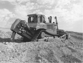
A ripper is a tooth, or set of teeth, which is usually mounted in a frame hinged to the back of a crawler tractor, with hydraulic hoist. It is pulled through rock or hard soil to break and loosen it.
The mounting may be a radial type, in which the teeth move in an arc, so that they tend to point downward in carrying position, and swing forward as they are lowered. A parallelogram or double mounting has two pairs of hinge arms, upper and lower, that keep the shank(s) at a constant angle to the ground as it is raised or lowered. See Figs. 21.1 and 21.2.
In an adjustable parallelogram, the upper arms are replaced by a pair of hydraulic cylinders which can be used to regulate shank angle, either before or during ripping.
Adjustment is useful in selecting an efficient point angle for a particular formation. It allows using a steep angle for entry, and a flatter, point-saving one for ripping. Dull points may sometimes be sharpened during ripping by changing from a steeper to a flatter angle.
The hydraulic pump and controls are built into the tractor, which should carry a bulldozer. This should have hydraulic tilt, for efficiency in handling oversize pieces of rock.
Shanks and Teeth. A tooth is made up of a long shank and the tooth proper, which may be called a point, a tip, or a cap.
A shank is usually fastened to a ripper bracket by two removable pins. If the bracket is open at the rear, teeth not being used may be stored as shown in Fig. 19.15.
Shanks may be straight or curved. Straight ones are generally used for massive or blocky formations; curved ones for bedded or laminated rock or road pavement that is further shattered by the lifting action of the bottom of the curve. Brackets may be loosely pinned to allow the tooth to swivel slightly to “hunt” weaknesses in rock, and to reduce side strain when the tractor is turned. They may allow for adjustment of depth of cut and/or angle of penetration.
Teeth are detachable, and may be reversible. They may be built up with hardface rod when worn, but this may spoil their shape and efficiency. It is better practice to weld on a forged cap.
Tooth points may have a service life of 30 minutes to 1,000 hours, most of the difference depending on the abrasive qualities of the rock. The operator should glance at them every time they come out of the ground. Dull teeth are inefficient, and worn-out or broken ones allow destruction of the shank.
Most heavy-duty rippers may be used with three teeth, with the center tooth only, or with the side teeth only. Use of all the teeth requires maximum power, works a strip somewhat wider than the ripper, and produces most thorough breakage where full penetration can be obtained. But it may limit depth and thoroughness, and even make any penetration impossible. Trouble may occur with slabs and boulders pushing ahead of the shanks.
Ripping with only the outer teeth increases efficiency of penetration, reduces power required, and usually produces coarser pieces than with three teeth. Breakage may be poor or lacking in the center, so that overlapping passes may be required.
Most very heavy ripping work is done with a single center tooth. All the weight and pull available can be applied to the single tooth, and it can hunt and follow weaknesses in the rock more readily.
FIGURE 21.1 Ripper with parallelogram mounting. (Reprinted courtesy of Caterpillar Inc.)
One mistake to be avoided is running the tractor for extended periods “on tiptoe.” Down-pressure on the ripper may raise the rear of the tractor, so that only the front of the tracks provides traction. See. Fig. 21.3. This reduces production, wears the undercarriage, and provides the operator with the roughest kind of a ride.
Rippability. The factors involved in the resistance of rock to ripping are discussed on page 3.5.
Penetration. Maximum penetration of general-purpose heavy rippers varies from about 10 to 60 inches (25.4 to 152.4 cm). Overall width between outer teeth may be 5 to 11 feet (1.5 to 3.4 m), to correspond with tractor width. A pair of D9 tractors can put as much as 60,000 pounds (27,000 kg) of down-pressure on a ripper tooth, making it possible to fracture very resistant rock.
There are also special-purpose rippers used in pipeline work, loosening coal, and subdrainage that may have single shanks permitting penetration as deep as 8 feet (2.4 m).
Heavy-duty rippers may be designed for operation by tandem tractors. The front machine carries and pulls the ripper; the second pushes it with a dozer blade held by a shelf or socket at the rear of the bracket or the shank.
The front tractor may do the whole job wherever it can produce good results alone, and be helped by the pusher only when necessary. The pusher blade may be allowed to float most of the time, with down-pressure only if the ripper tries to ride up.
Depth. Except when breaking hard or tough ground (pavement or frost) over soft material, teeth usually should be near full depth, with the pull beam approximately horizontal.
Shallow ripping tends to be irregular in depth, and causes tooth wear out of proportion to production.
FIGURE 21.2 Radial and parallel mountings.
However, there are a number of conditions that may call for part-depth ripping. Full depth may create too heavy a load, or may require so much down-pressure that the tractor is on the front of the tracks only (on tiptoe), with loss of traction and production, with increase in wear. Or the rock may have a natural horizontal weakness partway down, that should be utilized.
In any of these cases, it may pay to make a shallow cut. But if better depth can be reached easily by removing a tooth, or teeth, they should probably come off.
Direction. Any direction is suitable in soil, frost, rock with bedding planes parallel to the surface, and any material without a definite structure.
On slopes it is safest to rip up- or downhill, as large chunks might tend to lift and overturn the tractor. Difficult ground might be ripped downhill only.
When bedding planes or joint structure is at an angle with the surface, primary ripping is usually done against the grain, so that the slope of the beds tends to pull the tooth down. However, if this results in excessive pulling up of big slabs, another direction may be used.
If bedding planes are perpendicular to the surface, ripping should be across them. If parallel or nearly parallel, the tooth or teeth may tend to cut steep-sided grooves with unbroken ribs between them.
Whenever it is practical, tractors doing double duty as scraper pushers and as rippers, rip in the direction of scraper travel, to avoid turns.
Irregular depth and poor breakage can often be corrected by cross-ripping; that is, ripping the same area again at right angles to the original direction. The tractor must walk on rocks turned up the first time, and may find the going very rough. It may be necessary to push some of the pieces off to the side or to smash them before cross-ripping.
Spacing. Wide spacing means fewer passes, and therefore increased production on an area basis. However, close spacing may be needed, either to obtain reasonably even bottom breakage, or to produce pieces fine enough for removal by the equipment used.
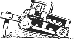
FIGURE 21.3 Tiptoe operation is poor operation.
With full penetration, 3 feet (0.91 m) between one-tooth passes is often satisfactory. Slab material may be loosened on spacings of 8 or even 10 feet (2.4 or 3.0 m), if the pieces can be handled. Crumbly material may call for wide spacing to reduce fines.
Slabs. Many formations, frozen ground, strong or rubbery rock with weak bedding planes, and concrete pavements tend to break out in big slabs that are pushed ahead by the ripper shanks, so that they lift the ripper out of the ground and/or jam against the tractor. A number of small slabs may combine to block multiple teeth.
A big slab may make it necessary to lift the teeth high, drive forward to clear it, lower the teeth to the ground surface, push the slab back until the teeth reach broken ground, then force them down to resume ripping. If the teeth are simply raised to clear the slab and forced in again at the other side, an unbroken pinnacle of rock will be left.
Slabs may be broken by forcing the tooth or teeth down on them, by climbing them with the tractor and turning, or by a separate machine with a drop ball or pile driver.
Operation. Most ripping is done in low gear, at 1 to 1½ miles per hour (1.6 to 2.4 km/hr). Higher speed tends to increase wear out of proportion to added production.
A torque converter reduces repair cost, as it cuts down both track spin and shock to the gear train. However, it may also reduce production substantially, particularly in rough work, as shock breaks even more rock than it does tractor parts.
Ripper operation in hard rough rock is the toughest service ever required of a crawler tractor. Hoist pull, down-pressure, and a portion of the drawbar pull are taken by the transmission case. An exceptionally solid rock mass may bring the tractor from walking speed to a dead stop in a fraction of a second. Tracks spin on smooth slabs, then are stopped abruptly by a grouser catching an edge. The underframe and power train cases may be hammered and jammed by pieces of rock too high for clearance, turned up by the tracks, or forced forward by the ripper. Reripping an area may involve constant pitching over loose rock, even after bulldozing the biggest pieces to the side.
Damage to the tractor and ripper is greatly affected by operator skill and attitude. A rough operator on such a rough job can wreck a new crawler in a season or less. A very careful person might be able to obtain almost as much production, and keep the machine running for its normal span of years, although repair costs will be high in this work. The careful operator will last longer, as bouncing a big tractor around on rock is rough on an operator’s insides.
Ripper Uses. The ripper has two principal uses in earthmoving. One is to make a diggable soil easier to dig, the other is to compete with explosives in loosening otherwise undigable material. Secondary uses include laying underground cable, cutting tree roots, and rolling out boulders.
The first use is a very old one, being chiefly employed in aiding scrapers and dozers to dig hard soil. The machine often has the double job of ripping, and pushing scrapers or bulldozing.
The use of rippers in soil being dug is discussed in Chaps. 8 and 19. The particular problem is that a very fine or loose soil is harder to load than one that is a little too hard for easy cutting. Ripping of a borderline soil may have the effect of decreasing production, or of not increasing it enough to justify the expense of ripping. Fine breakage with three teeth may cause loads to be smaller than if one or two teeth are used. Many contractors consider that if three teeth can be pulled through a soil at full depth, it does not need ripping.
A bulldozer does not have this problem, as it will almost always do better in loose soil than in formations that are even moderately hard. The worst that ripping can do here is to be a waste of effort. It cannot harm the digging and it usually helps it.
Production. A ripper designed for mounting on a 20-ton (18.1-metric ton) crawler tractor usually has an overall width of 9 feet (2.7 m) when carrying three teeth, and should loosen a 12-foot (3.7-m) strip. Maximum penetration is 2 feet (0.6 m) or more. In loosening soil or decomposed rock that is free from hard ledge or boulders, the ripper might be worked at full depth in low gear at a bit better than 1 mile per hour (1.6 km/hr), say 30 linear yards (27.4 m) per minute, less 5 yards (4.6 m) for turn time, leaving a net of 25 (22.9 m).
Multiplying this by the 4-yard (3.7-m) strip width, it covers 100 square yards (83.6 sq.m) per minute. At 2-foot (0.61-m) depth, this would yield 66 bank yards (50.4 bank cu.m) per minute, or 3,000 bank yards (2,295 bank cu.m), enough to keep a whole spread of scrapers in full-time operation.
Even after deducting one-third for contingencies, there is a very respectable 2,000 yards (1,530 cu.m) per hour. Potential production such as this is the reason that contractors try to assign ripping as just a part-time job for pushers.
Difficult soil containing boulders or frost or interrupted by ledges is loosened much more slowly. And all-rock ripping may go at a rate as low as 100 yards (91.4 m) per hour before it is given up. In very hard work, the work hour may be figured at 20 minutes.
In ripper work, most decreases in production caused by difficult ground conditions also increase machinery costs. There is probably no other earthmoving tool that shows such a wide range of output and unit cost.
Ripping is most apt to be profitable where the power is ample or even excessive for the job. A 10-ton (9.1-metric ton) tractor with a ripper might tear itself to pieces with little production in a formation that a 20-ton (18.1-metric ton) machine would walk through, loosening substantial yard-age with only moderate strain on itself. This larger machine might in its turn be nearly helpless in a harder formation that would yield easily to tandem tractors or a single 30-ton (27.2-metric ton) unit. The heavier and higher-powered units usually provide better and more uniform breakage than the overworked smaller ones. (See Fig. 21.4.)
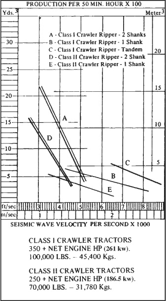
FIGURE 21.4 Ripper production graph. (Courtesy of ATECO.)
Ripping Cost—Rock. A thin, weak-bedded shale might be ripped at little more cost than hard soil. However, a really tough rock might prove so resistant that only one tooth could be used, penetration would still be poor, and breakage so difficult and irregular that production would be cut down to 100 cubic yards per hour (76.5 cu.m/hr).
A tractor ripping difficult rock is likely to be worn out within 3,000 hours if it keeps at it. Repair costs can easily be double those in ordinary heavy-duty service. If the right ripper is bought for the job, it should last at least as long as the tractor. Some heavy-duty rippers outlast two or three of the tractors that carry them.
Production may be substantially increased in many formations, and machine life lengthened, by light shake-up blasting before ripping.
If the ripper were strong enough, a pusher tractor with a down-pressure blade could be used, doubling both pull power and penetration rate. Assuming that the rock had good breaking qualities and just needed more force, output might be increased to 400 or even 600 yards (306 or 459 cu.m) per hour.
The tractor carrying the ripper would be under less strain, but the ripper would be under much more. The net effect would usually be a substantial reduction in repairs, and increase in tractor life. But even if no savings were obtained in this way, the pusher would add only 50 percent to costs, and would be paid for over and over by increased production.
Other Costs. Any comparison of ripping and blasting costs must take into account the method by which the broken rock is to be moved.
In a sidehill cut, it may be possible to sidecast the ripped rock with a dozer at a fraction of the cost of using a shovel in blasted rock. This would be true even if ripper breakage were coarse and irregular.
A dozer, often the same one that carries the ripper, may be used economically for pushing ripped rock up to 200 or 300 feet (61 or 91 m) along the road route to a fill. Production would be much better with fine breakage than with coarse.
For longer hauls the scraper is the preferred machine. If the material is suitable for scraper loading, it can probably move it for less than a shovel and trucks could. In the numerous formations that can be scraper-loaded after ripping, but not after blasting, the combined saving of ripping instead of blasting, and scraper instead of shovel, may be very substantial.
Where the rock cut is shallow, ripper-scraper combinations are even more desirable, because of the relative inefficiency of both blasting work and shovels or loaders in low banks.
But a scraper is not designed to handle coarse rock. Where ripper breakage is poor, scraper loading is likely to be slow, repair costs high, and useful life short. Scrapers may also be damaged at the dump by riding over rocks, and in struggles to eject oversize pieces.
On slopes, both fine and coarse ripped rock may be bulldozed downhill to belt loaders that put it into trucks, as shown in Fig. 14.18.
If the rock cannot be ripped into sizes for scrapers or belts, and there are too many big pieces to make it economical to break them with a drop ball, pile driver, or explosives, it will probably be necessary to bulldoze the rippings into piles for a front loader or power shovel.
The loader can do its own dozing. Work conditions are apt to be very rough, production low, and costs high.
If ripped rock can be pushed off a nearby face, the yardage from several layers can be heaped for efficient shovel loading. The cost of ripping can then be added to that for dozing, to get a figure to compare to that for drilling and blasting.
If there is no face to push to, or when repeated cutting of the top destroys it, the loose rock may be pushed up into windrows for the shovel. The shovel will not work efficiently, as side material will tend to slide away from it, and dozer help will be needed to keep the pile trimmed. For this condition the ripping method should be charged both with the piling expense and the lowered shovel efficiency.
Light Mounted Rippers. Figure 21.5 shows a ripper of lighter construction mounted on a heavy two-wheel-drive tractor equipped with a front loader. It is similar in design to the heavy units, except that it has four teeth and one ram.
FIGURE 21.5 Multiple-shank ripper on a wheel tractor.
This unit is primarily designed to loosen soils to be loaded by the same machine, but can do medium-duty rooting on many projects. It also serves as counterweight.
The John Deere subsoil plow may be carried on a hydraulic lift drawbar. It is essentially an agricultural tool, but will break up quite hard soils, and can prove a valuable aid to a light loader or dozer. It is inexpensive, readily mounted and removed, and does not interfere with many other uses for the tractor.
Either mounted or towed rippers can be used to lay cable and flexible conduit underground, without ditching. The soil is preferably even-textured. It is essential that the ripper be able to penetrate it and hold a reasonably even depth.
The cable may be mounted on a reel carried on the tractor; or may be laid on the ground and carried over or under the tractor by sheaves or tubes. See Fig. 21.6. One end is fed through a conduit or around sheaves to take it down the back of the single ripper shank and curve backward near the heel of the tooth.
This end is anchored at the beginning of the work strip. The tractor moves forward, the ripper makes a slot in the ground, the cable (or conduit) slides through its guides to be left near the bottom of the slot. The cut in the ground may heal itself, or be pressed together by one passage of the tires of a car or truck.
The ability of a cable-laying ripper or plow to penetrate ground, keep in line, and make minimum surface disturbance is improved by high-frequency vibration of the shank. However, the vibration may have an unfavorable effect on some types of cable.
The cable plow in Fig. 21.7 has a vibrating shank (saber) attached to a cable static chute by vibration-absorbing hinges. It is mounted on a category II, three-point hitch on a heavy wheel tractor with hydrostatic drive or creeper gears.
The special cable plow machine in the next illustration has the saber mounted under the center of a short-wheelbase four-wheel-drive tractor. It can swing 90° either forward or backward from its vertical plowing position, for starting and finishing a line. It can work up close to an obstruction on either end.
FIGURE 21.6 Cable-laying machinery.
The cable/pipe plow in Fig. 21.8, for mounting on crawlers over 70 horsepower (52.2 kw), can slide and swivel to both sides to permit cable laying either inside the track path, or at an offset to either side.
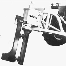
FIGURE 21.7 Cable layer with vibrating shank.
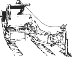
FIGURE 21.8 Side-pivoting cable layer. (Courtesy of ATECO.)
Tow Lines. Standard types of cable (wire rope) are used on winches. A 6 × 19 construction is most common. Independent wire core is recommended by manufacturers because of its greater strength, but many operators prefer fiber center because of its flexibility.
Wire core resists mashing, but if deformed it will not straighten out well under load so that it may become difficult to spool on the drum or feed through tackle.
Use of heavy cable decreases the length that can be wound on the drum and increases the labor of handling. However, land clearing which includes stump pulling usually requires the heaviest cable recommended for the winch. If lighter lines are used, the tractor should not be anchored and maximum pulls should be avoided.
Strength of cable is given in Fig. 12.49 in Chapter 12.
Light and medium cables are ordinarily attached to a tail chain and round hook. The chain is usually made of stock of the same diameter as the cable, and may be from 18 inches to 8 feet long (46 cm to 2.4 m). It should be made of high-strength or alloy steel, to give it substantially greater strength than the wire rope.
If the chain is long enough to make a complete choker around most of the loads or anchors, it may end in a standard slip or round hook. If it is so short that it functions merely to relieve the cable end of twists and kinks, it should have a hook with a wide, rounded inner surface which will do minimal damage to the rope wires. It is also desirable to have the hook end turned in, to minimize catching on obstructions when pulled in empty. See Fig. 21.9.
Winch lines of ⅞-inch (22.2-mm) diameter and larger may be fastened directly to a hook. Attachment may be by cable clips, wedge and socket, or poured fitting. Cable clips are light, easily obtained, and inexpensive, but are a nuisance to install, hard to remove, difficult to salvage, make a clumsy joint, and are apt to damage the cable.
Wedge clamps are comparatively easy to install and to take apart, can be used many times without replacement or repair, and do not damage cable. However, they are heavy and bulky and may be put out of action by loss of an improperly installed or tightened wedge.
Poured fittings are compact, light, and strong but require special materials and techniques for installation or removal.
A winch line may also be ended in a shackle, a cluster, a loop or a thimble, or a cable takeup with or without a swivel.
It is good practice to use separate attachment or choker lines. They are more readily repaired or replaced than the winch cable, and will serve to save it from the severe wear resulting from contact with the choker hook and load.
Chain. Towing chain is made in a variety of sizes, strengths, and designs, four of which are shown in Fig. 21.10. Size is designated by the approximate diameter of the round bar stock used in making the links, and ranges from ¼ to 2 inches (6.4 to 50.8 mm) or larger.
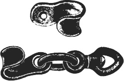
FIGURE 21.9 Cable-choker hooks.
Strength is determined by the bar size, by the quality and treatment of the steel, and to a smaller extent by the shape of the links. The table in Fig. 21.11 gives data for various types. The safe load shown is about one-quarter of the average breaking strength.
Alloy steel chain is very expensive, but is desirable for land-clearing work and load handling because of its light weight in proportion to strength. For example, ⅜-inch (9.5 mm) alloy chain is 30 percent stronger than ⅝-inch (15.9 mm) proof chain and weighs only two-fifths as much. In addition, the lighter chain gets a better grip on objects and can be passed through narrow spaces. Substantial savings in labor and machine time are realized from its use, but only in the hands of workers who will not abuse it or lose it.
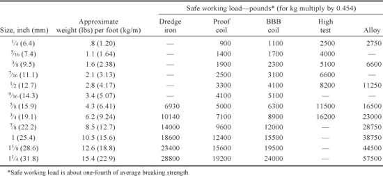
FIGURE 21.11 Chain weight and strength.
Alloy chain is almost standard for permanent attachment to winch cables. When used as a separate piece it should be dipped in red paint to distinguish it from less strong and valuable chain and to render loss less likely.
Short links are stronger than long ones but make a chain more balky and inclined to kink.
No chain should be subjected to load when twisted or kinked, as the links will be deformed and weakened. Twisting can be reduced if swivels are used in the chain or at the end hooks.
Hooks and Rings. The most-used chain fastenings are hooks and rings, some types of which are shown in Fig. 21.12. The standard logging or utility chain, Fig. 21.13, is of variable length, and has a round (slip) hook on one end and a grab hook on the other.
The round hook is used to form a choker that will tighten under pull. The chain is put around the load, the slip hook placed around the chain, which is pulled from the grab end. The chain tends to slide through the hook, increasing the tightness of its hold in proportion to the force exerted.
The hinged piece in the safety hook swings back automatically to admit a line, but it must be manipulated in order to release it. This prevents the hook from falling off the line when it is slack, avoiding delay and damage.
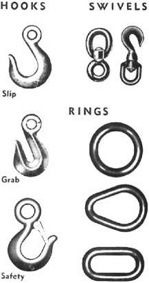
FIGURE 21.12 Chain fastenings.
Rings, which should be of heavier stock than the chain, are used in the same manner as round hooks. They are stronger than hooks and will not lose their hold when the chain is slack, but they are less convenient. A stump choker may be made by pulling chain through the ring, but anchoring to a tree requires releasing the other end of the chain and threading it through.
“Rings” are made in a number of different shapes. The three illustrated are the most popular. If two are used on a chain, one should be small or narrow enough to slide through the other.
The grab hook is used to form a chain loop that will not tighten. It slides over any link in the proper-size chain, as in Fig. 21.14, but will not slide along the chain.
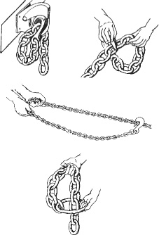
FIGURE 21.14 Grab hook uses, and stump choker.
Grab hooks can be used to shorten chains by lengthening the loop or by blocking the chain so that it will not slide through a drawbar or other opening.
Shackles, Fig. 21.15, can be used in place of rings or hooks for many purposes, and are handy means of attaching lines to objects. They can be used for emergency chain repair.
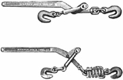
Load binders, Fig. 21.16, are used chiefly in tightening chains. The binder is expanded, the slack pulled out of the chain, and the hooks are attached to links on each side of the slack. The lever is pulled to shorten the binder, and locks over center. This process may have to be repeated on successive links. The handle should be tied down when left as part of a load lashing, as otherwise any slackening of the chain will allow it to fall open.
Load binders which do not have springs can be used with a chain to move heavy objects.
Repairs. It is common practice to overload winch and land-clearing chains to the point of destruction, with resulting heavy costs in repair and replacement. This is in part because the extremely heavy and variable pulls required to uproot tough stumps or to free jammed logs call for a chain which in ordinary quality is too heavy to handle and to use. High investment in alloy chain may be justified.
Broken chains can be repaired by hot forging of new links or by using special repair or connecting links, two types of which are shown in Fig. 21.17.
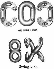
Such links are purchased assembled and separated by driving a chisel or a very sharp screwdriver between the pieces. This is most conveniently done in the shop.
If the links to be connected have pulled out of shape, it may not be possible to get the repair pieces through them. Such a link can be opened up by placing it on a block with a hole in it, and driving a big punch through it.
A good repair link is somewhat stronger than a standard chain link.
Snatch Blocks. A snatch block is a pulley or set of pulleys on an axle, which is held in a portable case that can be attached to one or two pull lines.
These blocks are generally employed to increase the force exerted by a line. They are used for hoisting, dragging heavy loads, changing direction of pull, and land clearing. The principles involved and their use in land clearing are discussed in Chapter 1.
Figure 21.18 shows several types of blocks. Single-sheave blocks should have latch fastenings that permit opening to insert or remove cable, but double and triple sheaves have solid cases.
The pulleys (sheaves) turn on a single axle. Self-lubricating bronze bushings are commonly used, but bushings greased through the axle and sealed antifriction bearings are also obtainable.
These general-purpose blocks can be obtained having a loose hook, a swivel hook, or a rigid or swivel shackle. The shackle is the strongest unit in proportion to weight, but is also the least convenient to use. Swivels have the advantage of allowing the block to adjust itself automati cally to line of pull, so that rubbing of the lines against the case is kept to a minimum.
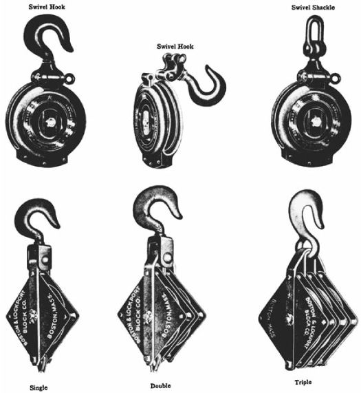
The latched blocks are much more efficient than the solid ones. The average hook or other attachment is too large to pass between the pulley and a fixed case so that it must be removed from the line for reeving. If it will pass, it is still necessary to thread the end of the cable through the block and to pull it out the same way. This takes much more time than inserting and removing the cable from the side, particularly when a number of blocks and lines are used.
Fixed blocks are often left rigged during moving, and crossing and tangling of lines may result, particularly if they are not pulled snugly together.
Figure 21.18 illustrates some heavy-duty blocks designed specially for land clearing.
When a choker cable or chain is permanently fastened to a block, the combination is called a power choker. One type shown is attached to the choker line by a shackle, and the other by a poured fitting. The shackle or loop on the opposite end makes it possible to attach an extra line, and to use the block as part of a direct line when the extra power of the pulley is not required.
Block and Fall. A block and fall is a set of light pulley blocks using fiber rope. See Fig. 21.19. In small sizes, pull is by hand. In larger units, several workers, a light tractor, or a horse may provide power.
They range in size from very small, 4 pounds (1.8 kg) or less complete with ⅜-inch (9.5-mm) rope, to heavy-duty models with 1-inch (25.4 mm) rope.
In the smallest sizes they are used chiefly for tightening fence wire. In general, they are useful in countless situations where required pull is greater than can be exerted by a worker, and machine power either cannot be readily applied, or might be too strong, fast, or jerky for the job.
Nylon rope should be avoided, because it stretches, wasting space and energy.
Root Hook. This is a very heavily constructed hook used for pulling small stumps, and individual roots on large ones. It is designed more for strength than for gripping power, and it is often necessary to notch a stump or dig behind a root, in order to give it a grip.
Tongs. Tongs are often used in place of chokers to grip loads that are to be hoisted or pulled. The type shown in Fig. 21.20 has points which are pulled into the load and which tighten automatically. It is sometimes necessary to tap the points in order to obtain the first grip. They can often be shaken loose after the load is placed, without hand work.
These are used for picking up or dragging loose stumps, logs, and similar objects. They are seldom used for pulling “solid” stumps, as considerable weight would be required to obtain sufficient strength, and the points have a tendency to tear through wood under extreme stress.
They are of particular advantage in handling objects which are so placed or piled that it is difficult to get chains under them, or to remove chains after they are placed.
The Johnson grubbing tongs shown in Fig. 21.21 grip with the inner surfaces of the arms. They are heavily built for rugged service in pulling stumps and trees up to 10- or 12-inch (25.4- or 30.5-cm) diameters, and can also be used for hoisting. Under many conditions they are more readily attached and detached than chains, and are of particular advantage when the pulling is done by a shovel dozer or some other machine which can carry them to the point of attachment.
FIGURE 21.20 Grapple hook and skidding tongs.
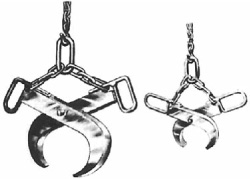
In heavy work, it is important to keep the line of pull straight through the tongs, as a side pull imposes excessive strain.
The bulldozer is an important land-clearing tool in itself. But its performance in this field can be extended and improved by replacing the standard connectors with special blades and devices, the more important of which are described below.
Perhaps the most necessary special construction for clearing is protection devices, for both operator and machine. A strong cab, OSHA-approved, should include an extra strong roof and verticals, and a rear protection of heavy screening. See Fig. 21.22. The radiator must have a strong, small-mesh guard. The engine must have side guards. Fine-mesh cab screening for operator protection against insects may be needed.
The operator must be constantly alert for falling trees and branches, for high stumps, rocks, and pits concealed by vegetation, for poles thrusting toward her or him, and for buildup of dangerous tensions in pushed material.
Stumper. The stumper in Fig. 21.23 is designed to fit over and be pin-fastened to the center swivel of an angling dozer C frame, or to a special frame operated by a bulldozer hoist.
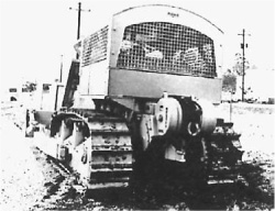
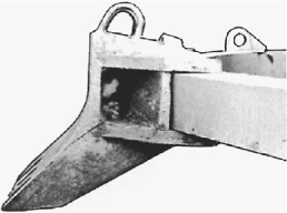
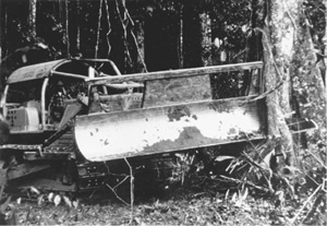
FIGURE 21.24 Tree dozer in action.
These tools are usually 2½ feet (0.76 m) wide, and have a drop below the C frame of 2 or more feet (0.61 or more meters). Construction is very massive. A serrated edge assists penetration in earth or wood, and keeps it from skidding to the side.
The stumper is used for pushing over trees and stumps, driving under stumps to boost them out, and digging around them when necessary. It is also effective in digging out boulders, knocking dirt off loose stumps, digging up railroad ties, ripping up shale and old paving, and making shallow ditches.
It concentrates the full power of the tractor on a narrow front. It makes possible cutting and lifting underground roots with minimum soil disturbance, and without wasting power in unnecessary digging of a wide strip of soil. It is not subject to the twisting strains which shorten the life of full blades used for stumping.
It is not good at piling or transporting loose stumps, or at backfilling holes or clearing brush. It should be teamed with a dozer or used alternately with a rake or blade on the same tractor.
Tree Pusher (Knockdown Beam). A tree pusher is usually a heavy tractor equipped with a dozer, stumping, or angle or V-blade, and a higher push frame with longer reach. See. Fig. 21.24. The push frame is preferably under separate control, but may be linked to the blade so that it is raised and lowered by its controls. Sometimes a pusher is carried without a blade.
Trees are pushed by the upper frame. This may uproot them, or just put them under heavy tension, so that the blade can drive under them readily to tear them out of the ground.
A V or angled blade can cast the tree to the side. Disposal is usually handled by other equipment.
V-Tree Cutter. A V-cutter for trees, Fig. 21.25, consists of a V-shaped, dozer-mounted blade fitted along the bottom with horizontal, scalloped cutting edges, and a center-mounted splitting point or stinger. Floats keep the edges from digging in.
The V-cutter is designed to shear off all vegetation at ground level, whether it is large or small, and to cast the debris to each side, where it is left for other equipment.
Trees that are too large to be sliced from the side are rammed and split by the stinger. The machine might then be able to slice the halves without stopping, or might have to back up to make additional passes.
Operation is most efficient on even-surfaced ground where the edges maintain good contact, where it is firm enough to hold the roots in position while the trunk is cut, and where there are no rocks hard or large enough to damage the cutting edges.
Under favorable conditions, cleared areas will be left entirely firm, and free of projecting stumps. The cut trees and brush may be pushed off by a dozer, preferably equipped with a rake blade.
Angle-Blade Cutter. This somewhat similar device has the stinger mounted on the forward end of a long blade set at a 30° angle. The full-length cutting edge is straight. See Fig. 21.26.
FIGURE 21.26 Angle-blade tree cutter. (Courtesy of Rome Plow Co.)
This arrangement permits dropping and pushing all trunks to one side and doing after-cutting windrow piling. In very heavy work, there may be problems with off-center loads.
The blade can be tilted downward to use the stinger as a stumper, or the whole blade in cutting shallow ditches.
Rake Blade. A rake blade may replace either a dozer blade or a front loader bucket, or be fastened by brackets and pins to a standard blade. It is made up of a set of tines that may be more or less vertical at top and center, and curve forward at the bottom. See Fig. 21.27. An upward extension, as seen in Fig. 1.2, is called a brush guard. There may be a solid center section to protect the radiator.
The tines may be operated below ground level to bring up roots and boulders, without moving solid masses of soil. However, separation does not usually occur automatically, except perhaps in dry sand.
Wet, sticky, or lumpy dirt may build across the teeth, blocking the slots between them, either by itself or after becoming matted with brush or roots. Under such conditions, it takes patience, skill, and experience to take growth (and rocks) and leave the soil behind.
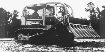
Rakes vary greatly in weight, strength, and tooth spacing, to suit various types of work. The heaviest ones, designed for grubbing out stumps, heavy roots, and boulders, must have tines so strong that any one of them can take the full push of the tractor without bending. Tooth spacing is usually wide in this type.
The lightest ones are intended for raking up loosened material on the surface, and for underground removal of light or weak root system. Tines are lighter and more closely spaced. They may be badly damaged by heavy work.
Heavy soils, such as clay and silt, are much more troublesome than sand, gravel, or loam. Almost any soil is easier to separate when dry than when wet.
Tree Shear. Tractor-mounted, hydraulic tree shears are presently able to cut hardwood trees up to 20-inch (51-cm) diameter, and softwood over 20 inches (51 cm). They snip or shear the tree a few inches (centimeters) above the ground. Capacity is reduced if the wood is frozen.
The unit in Fig. 21.28 is shown in open and closed positions. It is supported by a dozer (or loader) frame and lift. The left side (looking at it in this picture) is a massive fixed jaw or anvil, the right side is a hinged knife (cutter blade) that is moved by a powerful hydraulic cylinder.
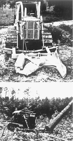
FIGURE 21.29 Accumulator to hold cut trees. (Courtesy of Rome Industries.)
The tractor is maneuvered until the tree trunk is between the knife and the anvil, which usually rests on the ground. The cutter is then forced through the wood. Unless badly out of balance, the tree falls across the anvil, away from the knife.
The shear may crush the bottom few inches of the trunk. A slice would have to be trimmed off saw timber, but not from a log to be pulped. No loss of timber is involved, as hand cutting is usually done much higher, and would leave more than that section on the stump.
Such a shear may be teamed with a handling device mounted on the same tractor. The accumulator in Fig. 21.29 is a double clamp that can hold one large tree, or a number of small ones, both while being cut, and while moving on to the next tree. When the arms are full, the tree or the stack is laid (piled down) on the ground, for dragging (skidding) away, or to be picked up by a chipper.
Root Plow. A root plow, or root cutter, is usually a horizontal knife, straight or V-shaped, supported by vertical standards or shanks at each side, and carried in a rear-mounted frame hinged to the track frames of a big crawler.
The model illustrated in Fig. 21.30 has a cable lift, but hydraulic operation is optional. Working depth is 8 to 20 inches (20 to 51 cm), depending on growth size, soil condition, and tractor power.
Angled fins slide roots up to the surface, but cleave through soil with little disturbance.
A fringe benefit from root plowing is almost complete loosening of soil, which increases water absorption. This good result may be accomplished with very little, if any, increase in erosion, which is retarded by innumerable fragments of vegetation left to rot in the disturbed soil.
Root Rake. Roots and stumps cut loose by the plow may be brought to the surface and piled by either a rake blade or a root rake. They are most effective in sandy soil and with coarse pieces. Heavy, wet soil, and fine matted roots, may cause almost constant clogging.
Towed Chain. Trees and stiff brush may be uprooted by a chain towed between two dozers of 180 horsepower (134 kw) or more. Chains must be very heavy, with bar diameter in the links being 2 to 3 inches (51 to 76 mm), and weight up to almost 90 pounds (40.9 kg) per foot. They should be about three times as long as the spacing between tractors, and 2½ times the height of the tallest tree.
One or more steel balls, from 3 to 10 feet (0.91 to 3.05 m) in diameter, which may be hollow, filled, or solid, may be fastened in the chain by universal connectors. They should be centered or equally distributed in the center half of the chain. Balls may serve to hold the chain up to slide over stumps and ridges, and to add momentum to overcome sudden resistance.
The chain should include several links, preferably one at each end and two in between, to prevent development of damaging twists. A supply of quick repair links should be available.
A third tractor with a pusher may be needed to follow the chain, and assist with stubborn trees, or lifting over obstacles.
It is often necessary to cover the area twice, in opposite directions, to complete the uprooting. But there is danger of loosened trees moving with the chain, and creating a massive, tangled pile.
The actual bulk of vegetation in any area is far less than it appears to be when it is standing, or even after if has been cut, uprooted, or piled. The difference is usually greater with brush and saplings than with trees with substantial trunks.
As a result, sufficient clearing for many purposes can often be accomplished by chopping vegetation into small pieces, without removing it. Such pieces may be partly or wholly buried by the chopping process, or left scattered on the surface.
When chopping involves partial burial, as by a disc harrow, the debris cannot be removed. Shredding and surface scattering by a rotary mower permit raking up for burning or removal, with increased difficulty in getting all the pieces. Chips are delivered through a spout, may be piled or scattered, but can conveniently be put directly in trucks for removal and possible use elsewhere.
Disc Harrow. Weeds, brush and small saplings may be knocked down, chopped or mangled, and partially buried by a heavy disc harrow. See Fig. 1.3.
These units usually have six or more concave discs, 2 feet (0.61 m) or more in diameter, with sharp, scalloped edges. They are mounted on an axle (or axles) whose angle to the direction of movement can be regulated. If it is parallel to the tractor’s axle, the discs roll freely; if at an angle, they cut down with a strong slicing effect, and mix and overturn the soil and vegetation.
At the best, the result will be well-chopped vegetation so well mixed with loosened earth that only a small part will be visible on the surface. The surface will usually have low parallel ridges, but might be almost smooth, and ready for planting with a cover crop, preferably some legume.
If the ground is too hard or rocky, or the vegetation is too coarse for the size harrow being used, there will be spots or areas where one or more of the functions—chopping, loosening, or burial—was not complete.
A single harrow sidecasts, somewhat in the manner of a plow, so that it leaves a furrow on one side of each pass and a ridge on the other. If the field is worked in straight lines back and forth, the line where the two directions meet will be left as a trough or a ridge. Skipped spots will create rough spots for the same reason.
In a rough field these irregularities probably will not matter. In cropland, they can be corrected at the next plowing, But they should be kept in mind when planning the work.
A bog harrow has two axles, which angle to both cast outward, creating a center trough and side ridges. These are smoothed by overlapping passes by a half-width.
In tandem construction, with two axles, one behind the other, the discs in the second set throw the opposite way from the first, thus eliminating troughing of the dirt except on turns.
Rolling Chopper. A rolling chopper is usually a big drum fitted with cutting blades, set in a tow frame with a draw tongue. See. Fig. 21.31. It is towed behind a tractor, usually a crawler, of 60 horsepower (45 kw) or more. Weight can be adjusted by putting water in the drum, or draining it.
A fully ballasted drum may put 1½ to 2 tons (1.4 to 1.8 metric tons) of weight on each foot of blade, providing a tremendous crushing and cutting force. Widths are available up to 16 feet (4.9 m). Smaller units may be towed in tandem, with different blade spacing on front and rear drums, or in triangular groups of three.
Choppers are usually pulled through standing trees and brush. The tractor should have a dozer blade or, for heavy growth, a tree pusher.
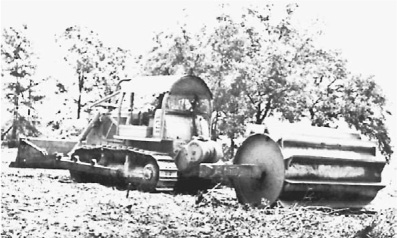
These units are generally used on jobs where the chopped vegetation can be left on and in the ground to decay. If the purpose is to produce rangeland for grazing, grass seed may be broadcast directly behind the towing tractor, so that the chopper will mix in and cover some of it.
A variable amount of material is mixed into the soil and buried, but this is usually not considered an important part of the result.
If the downed vegetation is to be piled, this may be best done by rake blades working at right angles to the direction of chopper travel.
The rolling chopper is most effective on ground that is firm enough to support sticks under the cutter, but soft enough to allow the cutter itself to sink in. Quality of work increases with speed, so it is advantageous to tow with a tractor powerful enough to use a high gear. Small stones do not bother it, but large ones interfere with the work and damage the blades.
The size growth that can be handled is limited by the ability of the tractor to knock it down, and by the resistance of the wood. Results vary with roller weight, tree type, and ground conditions. A few of the larger trunks on a job may be left almost intact.
Rotary Mixer. The rotary mixer is a machine that is used chiefly in mixing and stabilizing road bases and surfaces, but is also an excellent tool for clearing and mulching brushland. See Fig. 21.32.
A rotor assembly (Fig. 21.33), which consists of a shaft, tine-holding plates, and tines, is mounted across the direction of travel under a mixing chamber which controls the movement of materials so that two things are accomplished: first, a high percentage of the materials is deflected ahead of the rotors, so that constant remixing cycles are established; second, the material is at the final stage controlled in such a way that coarse and fines are mixed, blended, and placed so that aggregate segregation is entirely corrected. All sizes of the material it is working, from dust to the largest gravel, are uniformly distributed, the aggregate is keyed and interlocked, and the voids are filled with fines which create the most solid mass.
A rolled plate at the trailing edge of the mixing chamber acts as a strike-off to provide a smooth surface and to partially compact the mix. See Fig. 21.34.
Rotor speeds are controlled by a multispeed transmission and by the engine throttle. Depth of cut is regulated by raising or lowering the rotor relative to mixing chamber. Adjustable springs carry part of the rotor weight to permit it to ride over obstructions.
The tine-holding plates are driven by the shaft through individual friction clutches, designed to slip momentarily under shock loads. A variety of interchangeable tines can be obtained for different working conditions.
Smaller units of 3-foot (0.91-m) working width may be purchased for mounting directly on most wheel tractors of two-plow capacity or over, and still smaller sizes for garden tractors, but these are not adapted for industrial work. Principles of operation are similar, but there are wide differences in ruggedness and in details of construction.
All sizes are useful in landscape work. They pulverize topsoil, mix it thoroughly with subsoil, sand, fertilizer, humus, or any other material desired, smooth it off, and leave it in ideal condition for planting. They will chop up sod and weeds and mix them with soil, increasing its bulk and making its appearance more attractive.
The large motorized and self-propelled mixers do a good job of clearing brush and palmetto, and will handle trees up to 2½ to 3 inches (63.5 to 76.2 mm) in diameter. Light brush is cut up and completely buried; larger branches and trunk sections will be partly or wholly buried if the rear section of the hood is left down, or scattered on the surface for removal if it is raised. It is unsafe to walk behind the machine when the plate is up, as objects are thrown out with great force.
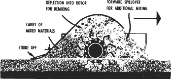
FIGURE 21.34 Rotary mixing action.
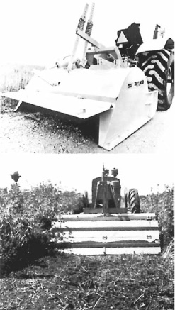
FIGURE 21.35 Heavy mowing for a rotary.
Rotary Mower. Rotary mowers, which in small sizes are the homeowners’ favorite for cutting the lawn, are also made in big, rugged models capable of mowing tall weeds, thick brush, and small saplings.
A heavy-duty rotary, such as the Bush Hog, Fig. 21.35, has a flat disc blade holder or flywheel fastened to the mower axle. Two heavy blades or flails are fastened to it by hinge pins.
When the blade holder is turning at high speed, up to 776 revolutions per minute, centrifugal force causes the blades to extend straight out, in cutting position, even against considerable cutting resistance.
But if a blade strikes something it cannot cut, it simply folds back on its hinge. It extends again immediately, and yields again at the next collision.
This arrangement entirely prevents shock damage to the shaft or drive, and limits blade damage to dulling or chipping. It also allows continued effort to cut or grind through the obstruction.
Most of these mowers are designed for mounting on the rear of medium-size wheel tractors with a three-point rear hitch. This allows positive (but not rigid) in-line fastening, and hydraulic lift. Drive is from the tractor’s power takeoff, through a shaft and universal joints. The shaft has a protective shield sleeve to reduce winding up of brush and vines.
In ordinary operation, the mower rests on the ground, supported at the rear by a swivel wheel that may be adjustable for height. In front it may rest on narrow skid shoes, and/or be supported by the hydraulic lift. Lower gears are used, the choice depending on the power available and the heaviness of cut. The engine is run at three-quarters to full throttle.
Quality of cutting is somewhat better going forward than backward, but the difference is usually not important. If the tractor has a reversing transmission, or a suitable reverse gear, mowing may be done neatly in straight adjoining lines, backward and forward. Otherwise the area may be cut by working inward from all sides, with some remowing of skips in the corners.
If cutting becomes very heavy, the engine will lug down and efficiency will drop sharply. It may be restored by raising the mower, if close cutting is not required. Or the tractor may be put into a lower gear.
In general, a heavy-duty rotary will chop up anything that its towing tractor can easily go over. For a 40-horsepower (30-kw) tractor and a 6-foot (1.8-m) mower, that would mean almost any thickness of brush, densely growing saplings up to 1½ inches (38 mm) in diameter, and occasional trunks up to 3 inches (76.2 mm).
Heavy stands often cannot be done in reverse, as they block the mower box. But for small pieces of cleanup at edges, or to chop piles of brush, the mower may be raised, backed into or over the material, and then lowered with the tractor standing still and the blades turning.
Most vegetation cut by this mower is left in rather short pieces, with considerable shredding, and it can usually be left on the ground to rot. However, a certain number of long pieces escape by lying flat on the ground. Sapling stumps may not be cut off flush, and might require repeat cuttings. Work is usually not as thorough and neat as the shredder’s.
Vines may wind around the driveshaft, and have to be cut off with hand clippers or a heavy knife. This trouble is greatly reduced by making first passes in reverse.
Rocks damage the blades slightly, and repeated contacts will wear them away or make them impossibly dull. The rocks themselves are often smashed.
The machine is dangerous, as it may throw rocks and other hard pieces with great force for more than 50 feet, chiefly to the rear. It should always be stopped if someone approaches it.
Rotary brush choppers are versatile and economical clearing tools, for work within their capacity. And they make excellent junior partners for bigger machinery, when controlling areas that have resprouted after clearing.
Brush Chipper. The brush chipper or grinder is the standard tool for processing hand-cut brush, saplings, and branches, wherever burning is impractical. See Fig. 21.36.
This type of vegetation is reduced to small chips by an engine-driven toothed cylinder or disc turning at high speed. The unit is usually mounted on a light trailer, and towed by a truck into which it can discharge the chips. It may be moved by a tractor on rough ground, or where complicated maneuvering is required.
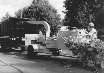
FIGURE 21.36 Brush chopper loading truck. (Courtesy of Vermeer Manufacturing Company.)
The chips have only a tiny fraction of the bulk of the brush that produces them. Where brush must be hauled away, 10 to 20 truckloads may be reduced to one load of chips.
On rough ground, in or bordering on fields and woods, the chips can be scattered to save hauling away. Small quantities are inconspicuous, and their decay adds compost to the soil. But piles or thick layers produce barren areas that may persist for years.
Cut material is fed into the machine by hand, in single stems or in bundles. The roller or its feed mechanism pulls them in. Great care must be taken not to allow hands to follow the brush. More time is usually needed than would be required to throw the material on a fire.
The chipper can usually be kept close to the cutting or gathering, so less carrying time is needed than with fires. Problems of building and maintaining fires, preventing spreading, and putting them out when leaving the area are all avoided.
Disadvantages include a high noise level, cost of purchase and maintenance, and consumption of fuel.
It is most efficient when kept close to the work, so that pieces can be ground as they are cut. If this is not practical, brush should be piled with all the butt ends facing the side where the chipper is to stand.
Tree Chipper. There are also chippers that can process full-size trees, up to 30-inch (0.76-m) diameter or more. The model in Fig. 21.37 is mounted on a semitrailer with a fifth wheel for connection to a highway-type tractor.
Its operator can pick up trees (or bunches of small trees) with a grapple, and place them on a chain conveyor and into the grip of vertical and horizontal compression rollers. These force it against a rotating 75-inch (1.9-m), three-knife chipping disc. See Fig. 1.26.
The chips are screened to separate fines (mostly bark dust) and oversize pieces. A conveyor and chute take them from there, and can be adjusted to load them into trucks, pile them, or scatter them.
The compression rolls are powerful enough to pull most trees into the cutter complete, without need to trim any branches.
The chipper accepts only cut trees, or uprooted ones with the stump cut off and discarded. Stumps are almost sure to carry dirt to dull the knives, and are likely to include rocks to chip or break them.
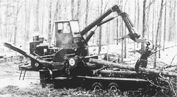
FIGURE 21.37 Self-feeding tree chipper. (Courtesy of Morbark Industries.)
FIGURE 21.38 Eliminating a stump. (Courtesy of Vermeer Manufacturing Company.)
In many areas, it is possible to sell chips to a paper mill, or to other wood product factories. Value depends on quality in relation to the processors’ requirements; possible profit may depend largely on haul distance. But it often pays to sell chips for less than cost, when other disposal methods would be more expensive. And utilization is greatly preferable to wasting.
If there is no market for chips, they may be sprayed on slopes for erosion control, usually in conjunction with tree planting, or spread thinly over the ground for decomposition into humus. But thick layers and piles should be avoided except in wasteland, as they may make the covered areas barren for years.
Stump Chipper. It is often difficult or impossible to get to a stump with equipment big enough to pull or dig it out. Even more often, the tearing up of the area and creation of a big hole are unacceptable. Hand digging is less destructive, but it is laborious and prohibitively expensive, and leaves a hole to be filled.
A stump chipper of appropriate size can chew almost any stump to chips, with little ground disturbance outside of its cutting arc. The work is done by a cutting wheel equipped with teeth, preferably carbide. Working depth is 6 to 24 inches (152 to 610 mm) in various models.
Figure 21.38 shows one of the larger and more sophisticated machines. It has a wheel carrying 48 teeth, some of which are on the rim, but most on both sides. This wheel can be lifted and lowered, and moved back and forth sideward continuously at a controllable rate during digging.
The unit is a trailer, attached to a light towing vehicle by a drawbar that can be swung from side to side by a hydraulic cylinder for accurate machine placement. Another cylinder extends and retracts the bar to move the unit and its wheel backward and forward during work.
The hole made by chipping a stump is much smaller than the one made by digging or pulling, as its lower parts are left in place. Chips may be used for temporary backfill, but they are loose, barren, and shrink with decay. Soil, or a mixture of soil and chips, should be put in for a longer-lasting repair.
It is economical to cut the stump off as close to the ground as is practical, before chipping it.
Stump chippers are used in land clearing, where stumps are to be removed after tree cutting, and in parks and built-up areas. Teeth are likely to be extensively damaged by contact with buried rock, so the wheel should be operated at slow speed and with great caution if its presence is suspected. Visible rock should be removed if possible.
Log Movers. There is a great variety of specialized equipment designed to move tree trunks and shorter logs from the place they are cut to a nearby processing or transporting facility.
A rear-mounted towing grapple has a pair of pincer arms that are closed hydraulically on the butt ends of a log or pile of logs, then lifted to tow them. See Fig. 21.39. A universal mounting allows the grapple and its load to swing and tilt, to accommodate turns and rough ground. The hoist may be either a direct or a parallelogram type, similar to those in rippers.
A grapple does not require the fastening of individual choker lines to the logs, but it may require that they be prepiled in position to be picked up.
The vertical and horizontal accumulators used for carrying sheared trees were mentioned earlier.
There are several clamp designs that replace loader buckets. They carry one or more logs, up to the limits of clamp size and loader stability, at right angles to travel direction. These need plenty of clear space, and there may be problems of catching ends against the ground, and of side tipping on slopes and rough ground.
The pumps most used by contractors are of the centrifugal and diaphragm types.
Centrifugal. The centrifugal pump, Fig. 21.40, operates by throwing water outward from a center by means of rapidly revolving vanes. The vacuum thus created at the center is constantly filled by water “sucked” (forced by atmospheric pressure) into it through the inlet passage. The velocity of the water thrown off the tips of the vanes creates pressure which drives the water out of the pump through the outlet passage.
In the construction of a centrifugal pump, as shown in Fig. 21.41, the water enters the system through a strainer at the bottom of a hose fastened to the inlet. A foot valve may be installed above the strainer to prevent the hose from draining when the pump is shut down.
The inlet hose is made of heavy plies of stiffened fabric and rubber which will not flatten under atmospheric pressure. It is usually made in 10- to 20-foot (3- to 6.1-m) sections. Each section ends in a metal coupling. Four-inch (102-mm)diameter and smaller lines usually have pipe thread couplings, while larger sizes have bolted flanges.
FIGURE 21.40 Centrifugal pump supported by safety raft.
The upper end of the hose may be led directly into the pump body or through an elbow, usually with an angle of 30 to 45°, which can be set in different positions by unbolting and rotating.
The hose-to-pump connections each include a small threaded and plugged hole. A vacuum gauge should be put in the inlet. This can be loosened or removed to admit air in order to drain a hose not equipped with a good foot valve, or to allow the pump to run without pulling water. The outlet fitting will take a pressure gauge.
FIGURE 21.41 Cross section of centrifugal pump.
The connector is fastened to the pump with a gasket, and hose flanges are fastened to each other in the same manner. Any threaded connections are smeared with sealing compound before connecting. Even very small leaks on the inlet side will substantially reduce the amount of water handled by the pump, and may stop it from working at all.
The pump body is a rigid casing which serves as a support for the pumping mechanism and as a tank to supply priming water.
The inlet check valve serves to prevent water in the tank from flowing back down in the inlet hose when the pump is stopped, will stop the outlet hose from draining if its end is underwater, and prevents siphoning of water out of a higher discharge point.
The diffuser or liner forms the inner shell of the pump. It provides an inlet passage by which water reaches the center of the impeller vanes, a plate which limits leakage of water or air past the back of the vanes, and peeler passages which take the water from the tips of the vanes and convert its velocity into pressure. It is the most widely used device to make a centrifugal pump self-priming.
The impeller consists of vanes curved back from the direction of rotation so as to minimize shock and turbulence where they hit the water at the center, and so as to give maximum outward velocity at the tips. They add a substantial wedging action to the centrifugal force.
Three types of impeller are in general use—the open, semiopen, and closed. Efficiency, maximum pressure, and ability to handle air are ordinarily greatest with the closed types, while the open ones are best able to pass solids.
The impeller is backed by the lantern which closes the front of the casing, carries the drive-shaft bearing a seal, and, with open impellers, prevents leakage past the front of the vanes.
In some makes, the diffuser and lantern are equipped with renewable wear plates facing the impeller.
The discharge or outlet tee is bolted to the top of the body and can be turned. The filler plug is removed in order to pour in water for priming a standard pump.
The outlet hose is of lighter construction than the inlet and will flatten out when empty. Couplings are identical.
The driveshaft extends forward from the impeller which is splined or keyed to it, and through the lantern to a direct connection with the engine driveshaft. Portable pumps usually have combustion engines, while fixed ones have electric power; but there are many exceptions to this generality. Electricity is more satisfactory where power is available because of ease of arranging for automatic operation and avoidance of the nuisance of fueling, lubricating, and adjusting the engine.
The driveshaft is usually on antifriction bearings, although bushings may be used. The rear bearing may be lubricated by the water in the pump, by an outside grease fitting, or may be sealed.
Priming. A self-priming centrifugal pump must be filled with water (primed) in order to function. The tank should contain enough water to cover the impeller. Water acts as a sealer of the clearance spaces next to the impeller, mixes with air to give it enough weight to be affected by centrifugal force, and serves as a check valve to prevent air on the discharge side of the pump from working back to the inlet. In most machines it provides lubrication for the shaft bushings and seals.
Contractors’ centrifugal pumps are of the so-called self-priming type. The pump will not prime itself—that is, draw the water into itself—when dry, but once it is filled with water, it will remain full and prime and re-prime itself through any number of starts and stops. And as long as water is in the tank, and the pump is turning, it tends to move air and water from the inlet to the discharge.
If the inlet hose fills with air instead of water, the pump is said to have lost its prime.
There are two general methods of circulating the priming water so as to pump air. The diffuser method depends on gravity forcing the tank water between the outer or discharge tips of the vanes, without its being able to reach the center because of their rotation. The water at the outside and the air at the inside mix where they make contact, and air bubbles are thrown from the impeller tips into the diffuser passages, from which they rise to the surface of the tank and escape through the discharge pipe, while the water continues to press against the vanes. This process is illustrated in Fig. 21.42.
As air is removed in this manner, a vacuum is created in the inlet pipe that causes water to rise in it until it enters the pump. The priming process is then complete. Water is forced through the pump hundreds of times faster than air, and vacuum increases sharply.
The recirculation method is to open a passage by which water can flow from the tank, which is on the outlet side, into the inlet passage. This mixes with air as it is caught by the impeller. On the discharge side the air bubbles to the surface, and the water returns to the inlet. Since the movement of air is quite slow, a very small leak may delay or prevent building up sufficient vacuum.
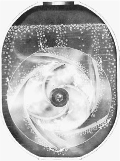
FIGURE 21.42 Diffuser priming action.
The height of the pump above water is an important consideration, as higher lifts require higher vacuums. A new pump may be able to pull water up 28 feet (8.5 m) (although volume handled drops rapidly with increase in lift), but a badly worn unit may have difficulty raising it 5 feet (1.5 m). Another factor is that under high vacuum, warm or hot water may evaporate so rapidly that the pump will be kept busy pumping water vapor.
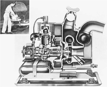
FIGURE 21.43 Hand-carry pump. (Courtesy of Homelite.)
Even a badly worn pump can draw water to a considerable height, once the air is exhausted. In emergencies, defective pumps may be primed by forcing water into the inlet hose from another pump, or siphoning water from a higher point through the discharge line, with the pump stopped. When the inlet is filled, the pump is started, and the direction of flow reversed.
In general, it is cheaper to overhaul a pump when it first shows signs of weakness, than to delay or lose work through its inefficiency.
Portables. In addition to the heavy wheel-mounted pumps, there are light hand-carry models [45 to 105 pounds (20 to 48 kg)] in 1½-, 2-, and 3-inch (38-, 51-, and 76-mm) sizes, that are made of aluminum and magnesium alloys, and driven by high-speed two-cycle engines. One is shown in Fig. 21.43. Electric drive is also available.
Their output is standard for their hose size, and their extreme portability makes them invaluable where access is difficult, and when jobs are small and scattered. They are handy where frequent changes of position must be made to follow a receding water level, and for keeping down inflow during work.
Several may be used in one excavation if there is too much water for one. They are ordinarily used on jobs needing intermittent rather than steady round-the-clock use, but contractors often keep them running for days at a stretch. An auxiliary gas supply can be rigged up to feed automatically into the pump tank, by a float valve in the tank, and a line to a drum or other container.
As with all two-cycle gasoline engines, it is absolutely essential that lubricating oil be mixed with the gasoline.
Jetting Pump. Jetting pumps usually are centrifugal pumps of heavy construction, so designed that they can deliver water at very high pressure but which have comparatively weak suction.
They may be of the self-priming construction described or may use an auxiliary vacuum pump for priming.
Their special uses include sinking foundation piles by water pressure, hydraulic excavating and flushing, making test holes, fire fighting, and dewatering where the discharge point is too high for the ordinary pump.
Well Point Pumps. These are centrifugal pumps which are able to handle water with a large proportion of air because of special internal design, or by means of auxiliary vacuum pumps.
They are used for removing underground water from the soil in excavation areas, and were discussed in Chap. 5.
One pump will be supplied from numerous points or inlets. These consist of pipes with gauze or slotted screens of fine mesh which are driven or jetted into the ground. The well points are connected with the surface by pipes which are connected to a main or header pipe to the pump through hose or pipes.
Diaphragm Pump. A diaphragm pump consists chiefly of a movable diaphragm in a closed chamber between two check valves, as seen in Fig. 21.44. The diaphragm moves vertically. On the upstroke it causes a suction which makes the inlet ball rise off its seat and pulls the contents of the inlet pipe. On the downstroke, the inlet valve is seated and the outlet valve forced open, discharging part of the contents of the chamber into the outlet pipe.
The action of this pump is positive, so that it will handle any material which will flow through the pipe. It is not subject to air lock, but because of its elasticity air moves through it slowly, particularly on high lifts.
It can be slowed or put out of action by trash lodging in the valves. For this reason, the valve chambers are made quickly accessible for easy removal of foreign matter.
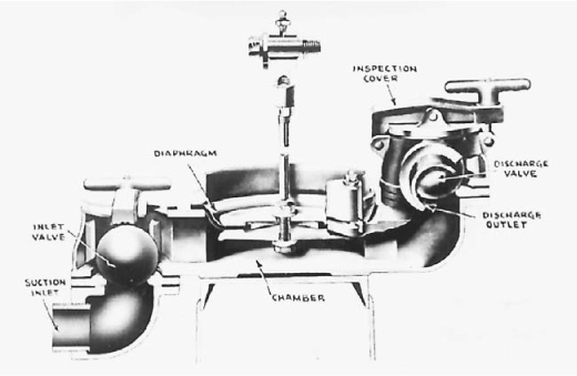
FIGURE 21.44 Diaphragm pump cross section.
FIGURE 21.45 Diaphragm pump ready for dewatering. (Courtesy of Gorman-Rupp Company.)
The maximum lift is somewhat less than that of the centrifugal pump, because some pressure in the intake line is required to open the inlet valve, and power is not provided for high outlet pressure. On high lifts it is good practice to set the pump about halfway between the inlet and discharge levels so as to equalize the resistance to the up- and downstrokes. See Fig. 21.45.
Problems of priming, of diminished output with height above water, and of impossibility of pulling water up more than 25 or 28 feet (7.6 or 8.5 m) may all be eliminated by placing the pump under the water, and providing power from above through a shaft, hydraulic lines, or electric wires.
Submersible pumps can be left unattended for hours, quietly working “overtime.” They can operate totally or partially submerged, so there is no need to move the pump as the water level changes. The pumps are designed to run dry for reasonable lengths of time without seal damage. Submersible pumps have no suction or priming problems. They have no suction hose. Just submerge the pump, and it is ready to go to work, providing higher heads for greater lifts than aboveground pumps of comparable size.
The pumps range in size from 1½ to 12 inches (38 to 305 mm), with capacities up to 7,400 gallons (28,000 liters) per minute (gpm) and head to 600 feet (183 m). The discharge of one pump can be connected through hose and couplings to the suction of another for tandem operation, which effectively doubles the head at a given flow.
Electrics. Small, submersible electric-powered pumps are commonly used for household water supply, where there is electricity readily available. For construction or mining sites, the electricity may have to be generated on the site. In either case, electric submersible pumps are very effective where large solids are not a problem.
A wide, solid base, as shown in Fig. 21.46, helps prevent the pump from turning into the ground or pumping its way into a hole. They are made in sizes from 2- to 12-inch (51- to 305-mm) discharge lines, with the largest having a capacity to 7,400 gallons (28,000 liters) per minute and a total head of 135 feet (41 m). An 8-inch (203 mm) model can handle a 600-foot (183-m) total head. Other models and sizes have maximum total heads of 100 to 300 feet (30.5 to 91 m) and maximum capacities of several thousands of gallons per minute.
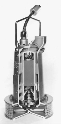
FIGURE 21.46 Submersible pump, cutaway. (Courtesy of Gorman-Rupp Company.)
There are also slimline submersible pumps for use in drilled wells, narrow cofferdams, and hard-to-reach places. They are more lightweight and easier to handle than the wide-base variety. The slimline design for a 2-inch (51-mm) pump, for instance, may be only 7½ inches (190 mm) at the widest. These pumps are provided in 2- to 6-inch sizes (51- to 152-mm), with capacities of several hundred to several thousand gallons per minute and total heads up to 300 feet (91 m).
Hydraulics. Hydraulic submersible pumps are designed for solids-handling construction dewatering applications and for pumping sludges and slurries, such as from mining operations. These pumps are powered by a gas or diesel engine-driven hydraulic power unit which provides up to 2,900 pounds per square inch (203 kg/sq.cm). Pump speed can be varied to suit job requirements, thereby allowing maximum efficiency and minimum fuel consumption. This makes them more economical to operate than generator-driven electric submersible pumps, which must operate at constant speed.
The hydraulic submersible pumps are available in 3-, 4-, and 6-inch (76-, 102- and 152-mm) discharge sizes with capacities up to 1,600 gallons (6,000 liters) per minute and heads of up to 175 feet (53 m). They will handle up to 5-inch (127 mm) diameter solids depending on the model. The 4- and 6-inch sizes (102- and 152-mm) are driven by a standard 63-horsepower (47 kw) diesel engine.
If the water is small in volume or contains a heavy load of mud or other solids, a diaphragm pump is preferred. For larger quantities of water a centrifugal pump is needed. Both light hand-carry and heavier wheel models of centrifugal pumps are available.
The most satisfactory results are obtained when the capacity of the pump or pumps is substantially greater than the inflow, particularly when there is a large volume of standing water.
Setting Up. The pump should be level and placed as near the water level as possible, as centrifugal pumps can push more strongly than they can pull. The table of output, Fig. 21.47, shows the loss in volume which occurs as a pump is raised above the water. The capacity of a pump is greatest when total lift is low.
The pump should be supported on a platform, or on boards as in Fig. 21.40. Otherwise vibration, and softening or washing of the ground, may cause it to settle off level, or even to fall into the pit.
A strainer should always be used when there is a possibility of sucking up stones or other objects which might damage or clog the line; and it is a good practice to use one whenever possible.
Use of a foot valve is optional. If the hose diameter is small, the lift low, the pumping steady, and the inlet opening unlikely to be exposed, it is not needed. On high lifts, particularly where the pump is worn and the inlet valve defective, a foot valve is very desirable.
Foot valves are not particularly dependable, being more subject to jamming by trash or mud than parts of the pump proper. In addition, the end of the inlet hose is frequently horizontal or nearly so, and some valves do not function well in this position.
Inlet Protection. The inlet should be well below the surface of the water—about six times the inside diameter of the hose when possible. This is frequently not practical, particularly when the place must be pumped dry.
At lesser depths a whirlpool may form over the inlet, and air enter through its center in sufficient quantity to form an air lock and cause the pump to lose its prime. Such a vortex will not form if the end of the hose is vertical, and is most likely to occur if it is horizontal.
The whirlpool may be prevented by digging a sump pit to lower the inlet; by floating a square or round piece of wood two or more feet (meters) in diameter over the inlet, or by bolting a roof over the strainer.
The inlet should not be allowed to rest in soft mud. It is liable to pick up abrasive material which will cause rapid wear of the pump; and may sink in sufficiently to reduce the intake or choke it off entirely. It is particularly apt to be choked when the pump is not running, and mud can slump into the hollow it has dug by sucking in soil with the water.
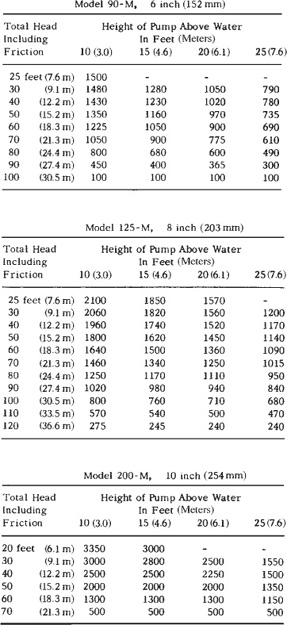
FIGURE 21.47 Pump capacities. (Courtesy of Contractors’ Pump Bureau.)
This can be prevented by resting the strainer in a wood box, or on a wide board. A light metal plate may be fastened permanently to the underside of the strainer.
When leaves, grass, or other vegetable debris is in the water, a strainer may become plugged every few seconds. The best cure for this is to make an additional strainer of wire of sufficiently fine mesh to catch the bulk of the trash, with a large enough area that the water will move through it at too low a velocity to hold the trash against it.
Even if too small for self-cleaning, such an additional screen will clog less often, and be more easily cleaned, than the standard strainer. Two constructions were illustrated in Chapter 5.
A riskier but less laborious method is to remove the hose strainer, and allow the trash to go through the pump.
Air in Inlet. A contractor’s centrifugal pump is built to handle solid water, and pumps air with difficulty. When the pump and inlet hose are empty, the pump must be filled with water (primed) before starting, and will then work for a while, slowly drawing the air out of the inlet pipe. When the water is sucked into the pump, its efficiency rises abruptly. If air is permitted to enter the intake, the pump will lose its grip, and have to again slowly work up enough vacuum to lift the water into it. This process is fairly quick in new pumps, but in worn ones is often a slow process if the lift is at all high.
Very often, failure of a pump to develop sufficient vacuum to prime itself is due to air leaks in the inlet line. These are most often past the gaskets at hose couplings, but may be at any spot on the inlet side. This includes the hoses themselves, the gasket between the inlet elbow and the body, cracks in the inlet or body, threaded fittings, loose or worn shaft packings, or lack of grease in a shaft bushing.
Such leaks are hard to detect, as, if the pump is worn or the lift is high, a very small leak will do the damage. Wet clay should be smeared over all suspicious spots on the hose, couplings, gaskets, or casing parts. This makes a good temporary seal for small leaks and will show up larger ones by disappearing into them. Leaks along the shaft will generally drip when the pump is stopped.
Gauges. The pump casing should be checked for cracks. Gaskets and connector threads should be smeared with pipe dope or Permatex #2. Installation of a vacuum gauge on the inlet side is an excellent idea, as it will immediately indicate the nature of the trouble. Low vacuum indicates leakage, a worn pump, or lack of prime water, and high vacuum a plugged inlet—usually the strainer, but sometimes a stuck valve. A fairly normal vacuum, with little or no production, indicates back-pressure from too high an outlet or a plugged line.
A vacuum gauge may be calibrated in pounds or inches (kilograms or millimeters). If pounds, it measures the difference between air pressure inside and outside of the inlet chamber in pounds per square inch. If inches, it indicates the height of a column of mercury which could be supported by this difference in pressure.
If the hose is full, vacuum will rise very rapidly to full pumping level.
Outlet or Discharge Line. If the outlet hose is not long enough to reach a disposal point, a level or downhill extension may be made by means of a wood flume, a ditch, or parallel dikes.
If the discharge hose end is underwater, the pump is stopped, and the inlet and foot valves leak or are lacking, water will siphon from the higher level through the pump and out the inlet. On a high lift, the force may be sufficient to turn the pump and engine backward. Otherwise the flow is leakage past the vanes.
If the discharge point is high, 30 or more feet (9 or more meters) above the pump, it may be advisable to install a check valve just above the pump, to relieve the pump of destructive water hammer when shut down.
If the outlet hose is long or crooked, pump capacity may be increased by using oversize hose. This reduces the velocity and friction of the water. Sharp turns or abrupt changes in size should be avoided through use of taper fittings and 30 or 45° elbows.
It is frequently desirable to reduce the output of the pump, as when the water level has been lowered and pumping need only remove an inflow which is less than the pump capacity. Gasoline power permits throttling the engine down. If this does not afford sufficient reduction, and it is not convenient to stop and start the pump frequently, a gate valve may be put on the outlet connection, and output regulated by opening or closing it. This does not add materially to the strain on the pump, whereas throttling the intake line does.
Freezing. Special precautions are needed to operate a pump in freezing weather. Whenever the pump is to be shut down, the body and hoses should be drained.
The drain plug at the bottom of the case, and the filler plug, should be removed. If the end of the discharge hose is above the pump and underwater, it should be lifted out to avoid siphoning water down to the pump.
The discharge hose can be emptied of water by holding it so that there is a continuous slope to the ends. If this is not practical, water can be worked out of it by raising it at the high end, and walking toward the other end, holding it up in a loop high enough to force the water over other high points. If the line is metal, it should be opened at its low points, and blown out if air is available.
If the inlet hose is light, it can be disconnected, pulled out of the water, and drained. If it is heavy, and has no foot valve, it may drain itself if the pump check valve is not airtight. If it does not drain, an opening should be made in the metal at its upper end. A petcock may be provided, or a vacuum gauge removed, or a new hole cut and threaded. The air admitted in this way will allow the water inside the hose to drop to the surrounding water level.
This opening must be sealed when the pump is used again.
If freezing is apt to be severe enough to form a plug of ice at water level in the hose, the opening at the top should be made large enough to permit pouring sufficient alcohol or fuel oil into the hose to protect it. If the hose is deep in the water, one dose should give protection for a long time if the pump is not used. Should the opening in the hose be close to the surface, alcohol may have to be renewed every few days.
If a foot valve is required for the pumping, it will be necessary to lift the lower end of the hose out of the water to open the valve to drain it unless a “tickler” is installed. Any homemade device which will unseat the flap in the foot valve by pulling on a line or a rod will be adequate.
If the pump body does not drain completely, it may be necessary to tip it to get all the water out, or to pour in enough alcohol to prevent the residue from freezing.
The use of salt or calcium chloride as an antifreeze is not recommended, because of probable damage to the pump.
The engine should be protected by antifreeze in the regular manner.
In freezing weather, it is advisable to start the engine before priming the pump, although it should not be allowed to run dry longer than a minute or two. If the temperature is below 0°F, it may be advisable to use hot water or a weak antifreeze mixture for priming.
If the pump is frozen, the engine will not turn over. Filling the tank with hot water or with a strong antifreeze solution should free it.
The outlet hose should be checked for ice before starting. Even if it has been drained, a small amount of water may collect in a low spot and glue the walls together. A hose blocked in any manner is liable to blow out under working pressure. Such ice can be readily broken by tapping the hose with a hammer or a block of wood.
Thawing an ice-blocked inlet hose is a major operation, and methods will depend on the facilities on hand. A gasoline-burning heater equipped with a blower and a warm air duct is most effective.
Under extreme conditions, a pump may freeze up while running. Provided the inlet is deep in the water, this may be prevented by wrapping hoses and pump body with sacking or blankets, or by applying heat (engine exhaust, bonfire, or large blowtorch) to the case. Flame should not be used if there are gasoline leaks anywhere, and caution should be used if the engine is oily or dirty.
Screens of various types are used to eliminate oversize stone from fill or crusher feeds, and to separate mixtures into uniform sizes.
In order for separation to take place, the raw material must be moved or shaken on the screen surface. Sticky or wet materials and fine openings require the maximum amount of movement.
Movement may be accomplished by gravity flow along an inclined screen, by rotating, shaking, or vibrating the screen, or less commonly, by raking devices. Some combination of gravity and other methods is usual.
Screens may be made of welded bars; sheet steel or rubber with round, square, slot, or octagonal holes; or wire cloth. Cloth is the most popular material in a wide range of applications.
A cloth may be described in terms of “space” or “mesh.” The difference is illustrated in Fig. 21.48. Space is the actual dimension of the clear opening between adjacent parallel wires. Mesh is the number of openings per inch, measured from center to center of parallel wires.
A square opening, whether in cloth or plate, will allow larger material through it than will pass a round hole of the same diameter.
Rectangular openings pass larger material than a square of their short dimension, but smaller than a square of the long dimension. Each shape rectangle will have different characteristics.
The wires in the cloth are crimped together—that is, bent under extreme pressure to a permanent set. Crimping may affect only one set of wires, or both. Various special arrangements are made to obtain extra tightness of connection, or to have the cloth smooth on one side.
FIGURE 21.48 Wire cloth measurements. (Courtesy of Hewitt-Robins.) (1 inch = 25.4 mm)
Manufactured screen cloth does not need to be welded, as the crimps hold the wires in place. Homemade cloth—usually made of bars for rough grizzly work—must be welded in order to keep it in alignment.
Rectangular openings are used when a steep screen slope reduces the effective length of the squares. Nonblind cloth may have the longer wires of a smaller size than the cross ones, so that they vibrate and tend to dislodge and pass pieces sticking between them. “Blinding” is the partial or complete clogging of the screen with inert material.
Gravity. A grizzly is generally a primary screen with fairly coarse openings that rejects boulders or large fragments from run-of-pit material.
Portable gravity grizzlies are shown in Figure 21.49(A), a light unit which is placed on a truck body before loading. Gravel or soil is deposited on the top of the slope and pours and rolls down along the surface, the undersize falling through the spaces and the oversize rolling clear. After loading, the shovel picks up the grizzly and places it on the next truck. A helper is needed to steady it during placement.
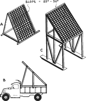
FIGURE 21.49 Portable grizzlies.
When used for stockpiling, it can be bolted to the truck body, as in Fig. 21.49(B). It must then not be high or heavy enough to overbalance the body in dumped position.
Figure 21.49(C) is a similar unit, built up on a skid frame. The truck backs under it to be loaded. It often becomes partly buried, and the frame should be strong enough to withstand heavy pulls. It may be braced between the skids also.
Figure 21.50 shows a fixed installation that may feed into trucks, a conveyor, a crusher, or a small stockpile.
These units may have screen surfaces of parallel steel bars or coarse mesh, supported by heavy cross members. The bars may be made of triangular, square, diamond, or round cross section, or of inverted rails. Mesh construction works more accurately than parallel bars.
A major difficulty with this type of screen may be slightly oversize rocks sticking between the bars. This trouble is least with triangular pieces with a flat side up, and greatest with round sections. A gradual increase in slot width toward the bottom is helpful.
Slot-type surfaces pass oversize flat rocks readily. If the underbracing is placed at such close intervals that the slots are reduced to squares, this difficulty is decreased. However, a wider bar spacing, or a longer slide, is then required to give the same capacity.
For a given material and bar spacing the amount of material passing through the grizzly will be increased by lengthening the screen or by reducing the slope. A long screen occupies more space both vertically and horizontally. A too-flat slope will allow material to rest on the surface and clog the slots. A too-steep or too-short slope will reject undersize material.
Spacing may be from 2 inches to 2 feet (5.1 cm to 61 cm), depending on the type of service.
Loose dry dirt will separate satisfactorily at a grade of 30 to 40°. Wet gravel or damp loam requires slopes up to 50°. Wet sticky materials cannot be satisfactorily processed.
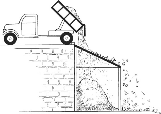
FIGURE 21.51 Vibrating bar grizzly. (Courtesy of Nordberg.)
Increase in width of slots will usually make it possible to reduce the slope or the length. Grizzlies used only to reject occasional large boulders, using bar spacings of 2 feet (61 cm), may be flat if some means of removing the boulders is provided.
Use of these units is restricted by inaccuracy of sizing, their tendency to clog, or the space required. They are desirable in that they can be built cheaply on the job, often out of scrap material, and are easy to operate and repair.
The slope of a grizzly can be reduced and the accuracy of sizing and capacity increased by shaking or vibrating the screen. Best results are obtained by purchasing a made-up unit, such as the one shown in Fig. 21.51, in which the screen has a limited movement relative to the frame and is connected to a shaking or vibrating device. Performance of a standard grizzly may often be improved by fastening a vibrator tightly to a side or top frame.
Complete plants for the processing of blasted rock, or of pit-run gravel containing oversize stone, perform the function of taking in a coarse and variable material and turning out one or more classes of graded and uniform product of greater value.
Equipment includes a hopper into which spoil is dumped by shovel, conveyor or haul units, screens to separate pieces according to size both before and after crushing, from one to three crushers to reduce oversize pieces, and hoppers or chutes and conveyors for individual handling of different sizes separated by the screens. Provision must be made for removal or storage of the products.
The plant units should be protected by a grizzly (coarse primary screen) on the hopper, which would prevent rocks too large for the passages or primary crusher from entering them. Feed from the hopper to the primary crusher or screens may be by gravity, apron conveyor, or belt conveyor. Such conveyors may be a few feet or several hundred feet (few meters or several hundred meters) long. They serve both to transport the material and to regulate the amount entering the crusher.
Mobile Crushing Plants. The portable plant, shown in cross section in Fig. 21.52, is a mobile, single-unit, double-reduction rock crushing and sorting plant designed for use in limestone quarries.
Even smaller portable crushing plants can be used on a jobsite to break up material, such as extracted asphalt road material or excavated rock, to make it suitable for fill material. This will eliminate the cost of hauling it away and probably cover the cost of moving to and using the crushing plant on the jobsite, as well as the cost of hauling in other fill material.
FIGURE 21.52 Portable crushing and screening plant.
The hopper may be protected by a bar grizzly to prevent the entrance of boulders too large for the primary crusher. Blasted rock may be dumped in the hopper by a shovel, conveyor, or trucks on a platform or bank.
An apron feeder carries the rock forward to fall on a grizzly, which passes pieces small enough not to require primary crushing, and slides the larger ones into the 18-inch (45.7-cm) by 24-inch (61-cm) jaw crusher.
This crusher dumps on a conveyor belt, which also carries the pieces that dropped through the sorting grizzly. Transfer is made to a second belt, which runs up an incline and discharges into a rotary elevator made up of a series of buckets carried inside a revolving drum which is set across the frame. This Rotovator elevates the load and drops it on an upper conveyor which discharges onto a three-deck screen.
Stones which fail to pass the coarse mesh screen on the top deck move forward into the secondary crusher, a hammermill. Product of the hammermill falls on the forward bottom belt, which takes it back to the screen.
Pieces passing the upper deck, but failing to go through either the second or third deck, slide forward into a chute opening onto the rock delivery conveyor. Movable gates are arranged so that when smaller sizes are required, the rejects from the second, or from both the second and third decks, may be directed into the secondary crusher. An extra “chip” conveyor can be installed with an additional chute to allow side delivery of two sizes of crushings.
Maintenance Truck. Whether it is a half-ton truck or a larger vehicle, earthwork contractors have found that it is profitable to have a maintenance vehicle available to service equipment in the field. The right vehicle, equipped with the tools and parts that frequently give out, is needed for onsite service and repair. The availability of such a vechicle makes a big difference in time and cost for repairs compared to getting the work done in a maintenance shop.
High-Pressure Fittings and Couplings. There are at least six different fittings which are attached to machinery to permit pumping grease. Of these, the most popular is the hydraulic fitting, Fig. 21.53. The gun nozzle or coupling, Fig. 21.54, contains jaws which are wedged apart by forcing them over the top of the fitting, and which clamp below the bulge. High pressure developed in the gun pushes against the head of the fitting and tends to push the gun away, but it also presses the tops of the jaws outward, wedging the bottoms inward for a tight grip. If grease passes freely and pressure is light, the gun can be removed by direct pull. If pressure is high, it is taken off by tilting sideward until the nozzle touches the shoulder and pries the jaws off.
The ball and spring should prevent grease from leaking back from the bearing. They are lacking in some small fittings.
These two types have the advantage of speed, with the hydraulic providing the more positive seal. If the machine is exposed to dirt or dust, the fitting should not be cleaned off after greasing, as the dab of grease sticking to it will prevent dirt from getting in the neck of the opening.
Standard threads are ⅛-inch (3.2 mm) P. T. (pipe thread), ¼-inch (6.4 mm) P. T. for oversize fittings, and ¼ to 28 inches (6.4 to 711 mm) for small ones. A variety of threads are available for special uses. Many small fittings have no threads and are driven in. These may not stand high pressures.
Large [¼-inch (6.4 mm) P. T.] hydraulic fittings are sometimes made of a small fitting screwed or driven into a larger base. The small part may come out when the coupling is pulled away. If much trouble is experienced, one-piece units, or ⅛-inch (3.2 mm) P. T. fittings in ⅛- to ¼-inch (3.2 to 6.4 mm) bushings should be substituted.
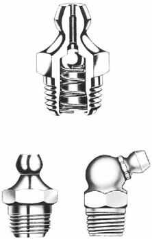
FIGURE 21.53 Hydraulic fittings.
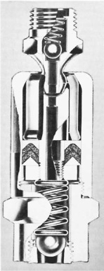
FIGURE 21.54 Hydraulic nozzle and fitting.
Hydraulic fittings are made in a variety of angles and lengths. Special extensions can be made up with ⅛-inch (3.2 mm) pipe material.
If grease leaks at the fitting-coupling connection, it usually indicates that one of these units, most often the fitting, has been scarred or damaged so that the coupling cannot seat properly. The defective part should be replaced.
The coupling may connect to it by pushing, pulling, or sideward motion. Leakage of grease around it usually indicates that the neoprene face seal is damaged or worn. The coupling cannot be pulled off while the grease in it is under high pressure.
The pin type is the original Alemite fitting. The coupling locks on it with a quarter-turn. This fitting projects farther than the others described, and is more subject to accident. Making connection is slower than with the hydraulic. It is no longer in wide use.
The Dot is made in standard and Mogul sizes. The gun is screwed on a full turn, usually forcing some grease into the fitting. Any additional amount required is then pumped in.
The flush type is used where the fitting cannot be allowed to project. It has limited use in earthmoving equipment because of the difficulty of cleaning.
Hand Grease Guns. The majority of hand grease guns now in production are the lever type. Figure 21.55 shows a typical example in cross section. The cylindrical barrel has a smooth inside finish. The metal piston with leather seals is pushed toward the head by a light spring. The follower rod is used to pull the piston back against the spring when refilling by suction. The collar groove in the rod permits locking it in the back position.
The head contains a fitting through which grease can be pumped into the reservoir, and a passageway from the reservoir into the nozzle tube. A piston actuated by the hand lever moves up and down in this passage in which a ball check is located.
When the piston is pulled up, grease or air in the tube is prevented from following it by the check. This leaves a vacuum so that when the passage to the reservoir is opened, grease is sucked into the passage. The grease is urged in by the pressure of the follower spring, and by atmospheric air entering the barrel around the follower rod in the back cap.
When the piston is moved down, it blocks the reservoir passage, then forces the grease down and compresses the check spring so that the grease can flow past the ball into the tube. When the piston is raised, the ball reseats itself and the passage refills from the reservoir.
The small piston and the comparatively long lever enable this gun to develop pressure up to 10,000 pounds per square inch (700 kg/sq.cm). Most nozzles and fittings are designed to take 20,000 pounds per square inch(1,400 kg/sq.cm) pressure. However, the seals and casings of the parts being lubricated will often bend or break at less pressure, so caution must be used when forcing grease into them.
The gun may be filled in three ways. The easiest is to pump grease into it through the fitting in the head casing from a loader pump. Precautions should be taken against pumping in air with the grease.

FIGURE 21.55 Lever-type hand grease gun.
If there is no loader fitting, or no loader pump is available, the head casing is unscrewed, the head of the barrel cleaned and pushed well down in the grease supply, and the follower arm drawn back slowly. If the grease is thin enough to flow, it will be sucked into the barrel. It may be necessary to move the gun around in the container to prevent air from entering. When the follower is fully back, it is locked with a sideward motion, the head screwed on, and the follower released. It is good practice to keep the grease in a warm place to keep it soft enough to flow.
If the grease cannot be pumped or sucked into the gun, it may be put in with a small paddle and air kneaded out of it. It is difficult to avoid air pockets with this method.
Air in the grease may form a pocket in the passageways that will prevent the gun from working. The block may be temporary until the air is worked out, or permanent if the gun is worn enough to allow it to return beside the piston into the reservoir.
Air takes much longer to get through the head than the same bulk of grease. However, many times a gun is said to be air-locked when the trouble is partly or wholly foreign matter which prevents the ball check from seating properly. This allows grease or air to be sucked into the cylinder from the outlet tube on the upstroke, and pushed back into it on the downstroke.
In either case the cure is to disassemble the unit, clean it, and pack it with fresh grease.
The outlet tube consists of a piece of ⅛-inch (3.2-mm) pipe, or of equivalent size flexible hose. Pipe thread is used. Any of the standard couplings can be attached to this.
Thick grease may not feed properly in this type of gun, as combined atmospheric and spring pressure may not be enough to make it flow. It may be persuaded to work by tapping or by heating. Best results may be obtained if the follower piston is so built that the rod can be locked to it (as in this example), so that pressure can be applied while pumping.
A special gun may be obtained in which the grease is forced along the gun by twisting a threaded follower.
The push-type gun, Fig. 21.56, is convenient for narrow spaces and high spots. The newer models may be filled through the loader fitting shown, but for older types it is necessary to remove the backplate, pull out the follower, and pack it by hand. The amount of lubricant in the gun is indicated by the distance the follower handle projects.
The gun is held by the handle and pushed against the fitting. After the coupler grips, the end of the gun slides on a plunger which pushes the grease out of the stem into the fitting. Pressure is then released, the spring forces the gun back, the stem fills with grease, and it is ready for the next push. A ball check in the coupling prevents air from entering the stem.
Screw-type guns are of simple construction. The follower rod is threaded, and screwing it into the rear cap forces the follower piston against the grease, which passes directly into the coupling.
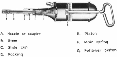
FIGURE 21.56 Push-type hand grease gun.
FIGURE 21.57 Multipressure bucket pump. (Courtesy of Alemite Corporation.)
Bucket Pumps. As used here, this term includes all large-capacity hand-operated grease pumps. Pressure varies from a few pounds for transfer pumps up to 15,000 pounds per square inch (psi) (1,050 kg/sq.cm) in heavy-duty models.
Such pumps generally consist of a pail, a pail cover, a hand pump fastened in the cover, a flexible hose, and a coupling or nozzle. An Alemite bucket pump is shown in Fig. 21.57, good for pressures from 2,500 to 5,000 pounds per square inch (psi equal to 175 to 350 kg/sq.cm) and 35 pounds (15.9 kg) or 5 gallons (18.9 liters) of lubricants.
The pressure release lever opens a bypass so that grease pumped is returned to the tank, and the hose can drain back into the tank also. This allows the release of any pressure binding a coupling on a fitting, allows the handle to be pushed down to carrying position without forcing grease out of the coupling, and allows priming the pump after refilling, without forcing air into the hose.
Air-Operated Pumps. Wherever possible, grease is pumped by compressed air. Many pumps are intended for use in a standard 55-gallon (208 liters) [400-pound (182-kg)] drum.
A single vertical rod connects the piston of a one-cylinder, double-acting air motor to the grease pump piston. This is hollow and carries a ball on a machined seat at the bottom. When the piston moves down, grease unseats the valve and fills the piston. When it moves up, the ball seats and the grease is forced up the space around the piston rod and out toward the nozzle.
The mechanical primer is a large plunger which moves grease toward the ball check with each upstroke.
When this unit is connected to the air line, it pumps until full pressure is built up in the grease line. This pressure then shuts off the air by closing the passage through the trigger valve. The unit is then said to be balanced. When grease pressure drops, air is admitted again and pumping is resumed.
These pumps are available in high- and low-pressure constructions, and similar units dispense oil in large volume and at very low pressure.
Grease Trucks. A contractor who has ten or more pieces of equipment in the field may consider the advisability of buying or building a mobile greasing unit to take care of the lubrication requirements. Such units are shown in Fig. 21.58. This is only a sample of a posible arrangement. A wide variety of equipment and many layout plans are available.
It is important that the lube truck be sized for the requirements of the contractor’s equipment in the field. If it is too large, it probably will not be used or will be too costly to use, but if it is too small, it cannot get its job done.
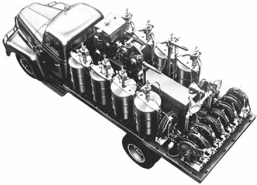
The usual carrier is a flatbed truck with a capacity of 2 tons (1,820 kg) or more. A beefed-up pickup may carry a small unit. A van-type body may be used when the climate is cold or rainy. Four-wheel-drive trucks are used for rugged conditions. Semitrailers are suited to part-time use, as they can be parked and the tractor used for other jobs.
A grease truck may carry from 2 to 10 drums of grease and oil, each weighing about 400 pounds (182 kg); a gasoline engine that drives an air compressor, an air pump in each active drum (spares may be carried), and a reel of hose for each lubricant.
The reels receive grease through their axles and feed it into a connection to the hose. They may be hand-wound or equipped with pullback springs that allow the hose to be pulled out, then wind it back when it is released.
The nozzles may be plain or equipped with meters. Pressure in the hoses is automatically maintained by the air pumps.
The truck may carry drums of fuel, antifreeze, and/or water in addition to the lubricants. If it is not needed full time for greasing, it may be equipped with a small electric generator, drills, lights, vise, and tools, so that it can be used for field repairs.
Lubrication may be done by one or two workers. The time per machine is highly variable. Some have only 1 to 3 points for daily greasing, others may have 30 or more. In addition to daily lube jobs there are more extensive lubrications required weekly or monthly, and changes of engine, transmission, final drive, and hydraulic oil are made according to hourly or seasonal schedules.
Machines that are lined up together at the end of a shift may be lubricated by one person at the rate of 2 to 12 per hour, with a long-term average of 3 to 5. Those that have to be found where they are scattered around the job require additional travel and search time. If the system is to catch and stop machines at work, time will be longer and interference with work may be costly.
Time spent by the grease crew, or the number of lube trucks and crews required, may be greatly reduced by having operators take care of light lubrication themselves. A few contractors go further and leave all lubrication to operators and oilers, paying overtime for the work.
When lubrication must be done during workhours, trucks can be most effectively done by a stationary unit, or a mobile unit parked along the haul route.
A survey made by the magazine Construction Methods and Equipment indicates that contractors use one grease truck for 7 up to 110 pieces of equipment, with the usual range being between 20 and 80. Some, with as many as 80 nonhighway units, relied entirely on hand greasing and/or fixed grease racks.
With mobile construction equipment, such as scrapers and trucks, getting bigger and bigger, it is essential that their tires be handled by heavy machinery. That is the role of machinery seen in Fig. 21.59. The IMT TireHandler offers a choice of loader-mounted, forklift-mounted, or hydraulic crane-mounted models. These can handle tires from 25 to 164 inches (0.63 to 4.17 m) in diameter and up to 25,000 pounds (11,400 kg).
FIGURE 21.59 Handling tires of equipment. (Courtesy of IMT.)
FIGURE 21.60 Movements of tire handler. (Courtesy of IMT.)
The TireHandler provides a natural, more efficient way for an operator to hydraulically grip, pull, lift, turn, and position a tire. The operator in the loader, forklift, or crane can do it all from the safety of the control console. The tire body can be rotated up to 390° in a vertical plane, rotated to a horizontal plane for carrying with an unobstructed view, and moved laterally so the operator does not have to jockey the equipment for a more perfect approach for installing the tire. See Fig. 21.60.