35.1 If You Aim at Height Restoration, Mind the Access!
Alessandro Cianfoni
Some of the original intended advantages of balloon kyphoplasty (BKP) were to achieve height restoration and spinal realignment in patients with vertebral fractures, but BKP has inconsistently shown to be able to obtain significant fracture reduction.1 Up to one-third of BKP-treated cases show no appreciable height restoration, either because the balloons expand in trajectories that produce inefficient internal fracture distraction or due to the loss of previously restored height and kyphotic realignment after balloon deflation.2
Newer percutaneous devices have been introduced to achieve fracture reduction and kyphosis correction and are used along with vertebral cement augmentation. Two of these systems, vertebral body stents (VBS; DePuy Synthes-Johnson & Johnson) and SpineJack (Vexim-Stryker), offer the possibility to perform a kyphoplasty with an internal framework that consists of rigid devices that produce internal vertebral body distraction. The devices expand in a different manner than balloons that expand spherically and centrifugally. These devices expand in a predictable manner and in a way that exerts a strong predetermined craniocaudal distraction force perpendicular to the major fracture axis.3–7
In order to allow the device to perform its craniocaudal distraction force and obtain the most efficient fracture reduction and height restoration, the axis of insertion of the device in the vertebral body is of paramount, yet sometimes underestimated, importance.
While the transpedicular access used to perform vertebroplasty and BKP aims at the safe zones at and around the pedicle to stay as far as possible from the medial pedicular cortical boundaries, in kyphoplasty with structural implants the pedicular access should be adapted in order to obtain a device placement inside the vertebral body along an axis parallel to the anticipated alignment of the original prefracture end plates (▶Fig. 35.1). When only one end plate is fractured and deformed, the axis of device insertion can be parallel to the intact end plate. The distraction performed perpendicular to this axis approximates the original prefracture shape of the vertebral body and allows the device to achieve maximum expansion and fracture reduction (▶Fig. 35.2 and ▶Fig. 35.3). A different axis of insertion of the device causes the distraction force to be incident with an angle that is nonperpendicular to one or both end plates, thereby resulting in less efficient fracture reduction and increases the risk of iatrogenic end plate disruption that can limit the device expansion to a lesser degree of height restoration than is optimal.
It is not always easy to obtain insertion of the device along the desired axis. The most frequently injured portion of the vertebral body in compression fractures is the superior end plate, often creating an unfavorable access angle between pedicles and superior end plate. In such cases, the transpedicular access is performed through the most caudal aspect of the pedicle and then advanced just tangentially underneath the superior end plate (▶Fig. 35.1).
Accessing the caudal part of the pedicle poses some technical challenges:
• During the trocar docking into the cortex of the posterior elements, the trocar tends to slide caudally and poses the risk of inadvertently entering the neural foramen.
• The caudal aspect of the pedicle is often smaller than the cranial part; attention should be made not to violate the medial pedicular cortex that protects the central canal, and the inferior cortex that protects the neural foramen (▶Fig. 35.1).
We suggest the use of a beveled tip low-profile (12- to 14-gauge) trocar to perform the initial access so as to be able to dock and steer along the optimal access path. This will provide the maximum control and precision placement of the trocar, especially while sliding under a fractured end plate. The initial access is then followed by insertion of larger access trocar via using k-wire exchange. The larger trocar is then able to accommodate the placement of the distraction devices (▶Fig. 35.2).
When the access is correct, the expansion of the distraction device can occur in an optimally craniocaudal orientation within the vertebral body, thereby maximizing the chances of full vertebral body height restoration and kyphosis correction (▶Fig. 35.2 and ▶Fig. 35.3).
If you are aiming at fracture reduction, to restore the prefracture vertebral body height in order to optimize pain relief, physiological biomechanics, and to prevent more fractures of adjacent and distant vertebral bodies, mind the access!
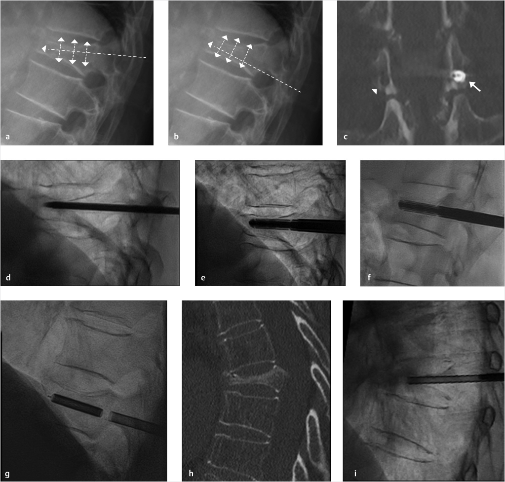
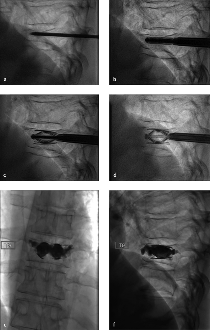
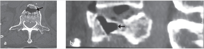
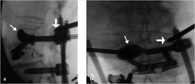
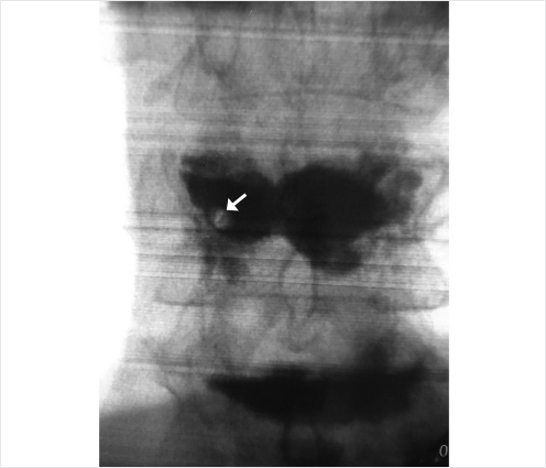
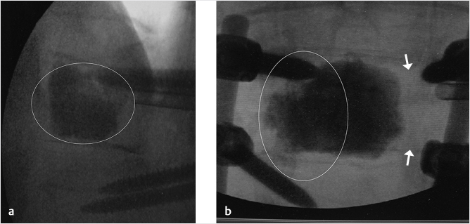
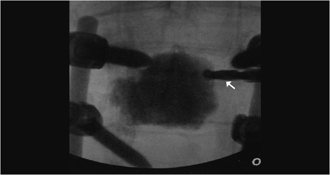
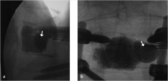
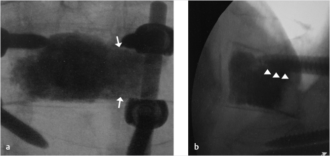
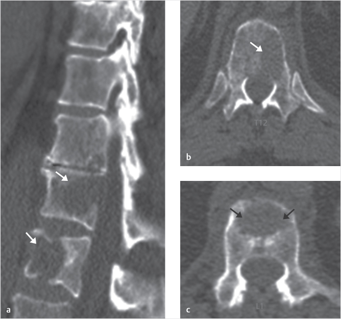
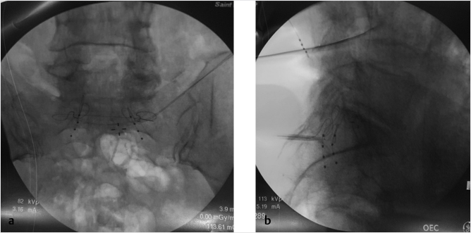
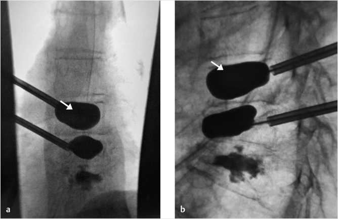
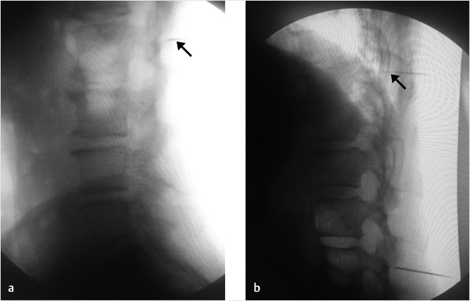
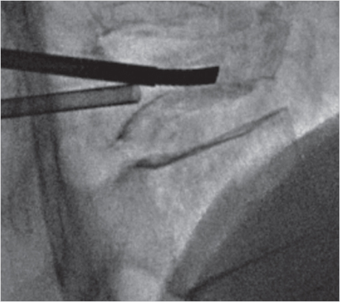
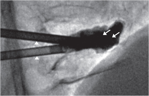
Fig. 35.1 Examples of pedicular accesses to achieve height restoration. In (a) and (b) schematic drawings on lateral X-ray views of the thoracolumbar junction represent two axes of transpedicular access to the wedged vertebral body of T12. The superior end plate is more deformed than the inferior end plate. (a) A standard access (dashed long arrow) in the center of the pedicle that could be easily performed and used for a vertebroplasty. If used to insert a distraction device to achieve height restoration, the perpendicular forces (small arrows) exerted by the device would have an incident angle on both end plates that would prevent efficient height restoration. (b) The long dashed arrow represents a more correct axis to insert and operate a distraction device. The access is along the caudal aspect of the pedicle with the small arrows predicting how the device would exert fracture reduction and more efficiently reconstitute vertebral body height. (c) A postprocedure coronal multiplanar reconstructed CT image showing the hole left by the trocar in the inferior portion of the pedicle on the right (arrowhead) and the pedicular screw on the left (arrow). (d–g) Four examples of transpedicular access along the inferior portion of the pedicle, to insert the distraction devices (12-gauge trocar in d, Spinejack in e and f, vertebral body stents [VBS] in g), along the correct axis, parallel to the intact inferior end plate. (h) A sagittal multiplanar reconstructed CT image of a midthoracic vertebra plana and (i) its corresponding intraprocedural fluoroscopic image showing access to the vertebral body between the collapsed end plates (cannula shown in i).
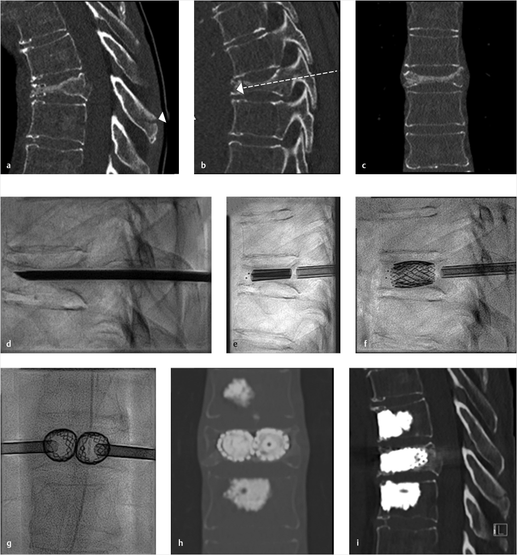
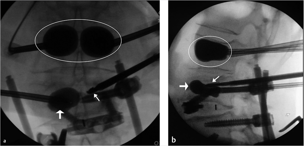
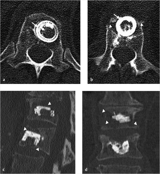
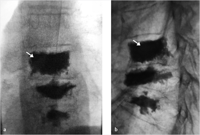
Fig. 35.2 Height restoration in a vertebra plana with vertebral body stents (VBS). (a–c) Multiplanar reconstructed CT images of a T8 vertebral compression fracture with vertebra plana deformity. (a) Midsagittal image showing the focal kyphosis due to the collapse of the vertebral body and a fracture of the spinous process (arrowhead). (b) It is important to look at the sagittal image through the pedicles to study the angle between the pedicles and the fractured superior end plate that influences the axis of the pedicular access (dashed arrow). (c) Coronal image showing the prominent collapse of the end plates. In the cases with prominent central collapse of the vertebral body, a more anteroposterior trocar approach, lateral to midline, will be favored. (d) The beveled tip trocar is inserted through the caudal aspect of the pedicle and precisely steered and advanced between the end plates. The trocar is then exchanged over a k-wire with a larger access cannula that allows the insertion of the balloon-mounted VBS (e). (f, g) The balloons are inflated and the VBS deployed. After cement augmentation, (h, i) the postprocedure CT images show the fracture reduction, with significant height restoration and kyphosis correction.
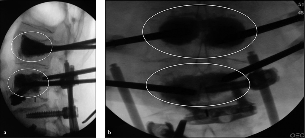
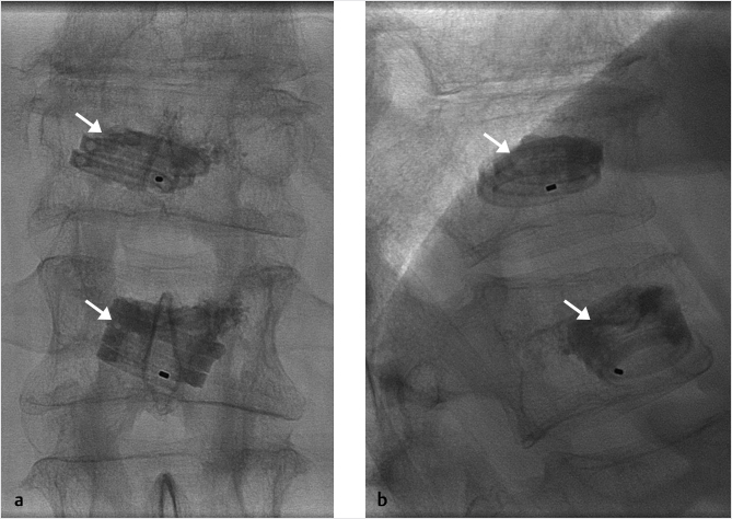
Fig. 35.3 Height restoration with Spinejack. Lateral fluoroscopic images show a posttraumatic T9 compression fracture, with more than 50% vertebral body height loss. Both end plates are fractured and deformed, but their alignment is nearly parallel. The beveled tip trocar in (a) is placed along an axis parallel to both end plates. The trocar is placed along the caudal portion of the pedicle and sliding just underneath the superior end plate. This access allows insertion of the Spinejack distraction devices parallel to the expected prefracture end plate alignment (shown in b) that allows a craniocaudal distraction of the Spinejack leading to efficient fracture reduction and height restoration (c, d). Cement augmentation completes the procedure, as shown on postoperative (e) anteroposterior and (f) lateral fluoroscopic images.
References
[1] Beall D, Lorio MP, Yun BM, Runa MJ, Ong KL, Warner CB. Review of vertebral augmentation: an updated meta-analysis of the effectiveness. Int J Spine Surg 2018;12(3):295–321
[2] Disch AC, Schmoelz W. Cement augmentation in a thoracolumbar fracture model: reduction and stability after balloon kyphoplasty versus vertebral body stenting. Spine 2014;39(19):E1147–E1153
[3] Rotter R, Martin H, Fuerderer S, et al. Vertebral body stenting: a new method for vertebral augmentation versus kyphoplasty. Eur Spine J 2010;19(6):916–923
[4] Diel P, Röder C, Perler G, et al. Radiographic and safety details of vertebral body stenting: results from a multicenter chart review. BMC Musculoskelet Disord 2013;14:233
[5] Wang D, Zheng S, Liu A, et al. The role of minimally invasive vertebral body stent on reduction of the deflation effect after kyphoplasty: a biomechanical study. Spine 2018;43(6):E341–E347
[6] Noriega D, Krüger A, Ardura F, et al. Clinical outcome after the use of a new craniocaudal expandable implant for vertebral compression fracture treatment: one year results from a prospective multicentric study. BioMed Res Int 2015;2015:927813
[7] Noriega D, Maestretti G, Renaud C, et al. Clinical performance and safety of 108 SpineJack implantations: 1-year results of a prospective multicentre single-arm registry study. BioMed Res Int 2015; 2015:173872
35.2 Pearls of Vertebroplasty and Kyphoplasty
Deborah H. Tracy
There are several important pearls in accomplishing an accurate needle placement and an optimal fill, and good post-op outcomes when performing kyphoplasty or vertebroplasty. These techniques include using last image hold, utilizing a bevel needle for maximum needle steering capability when driving the access needle, magnifying the image if visualization is difficult, and dressing the wound site with steri-strips, which can be left on for 5 days.
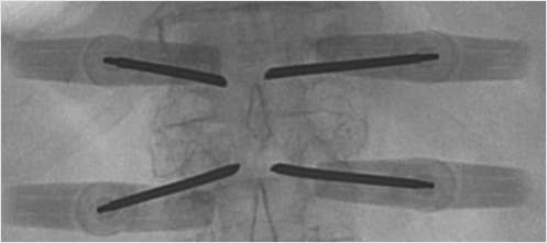
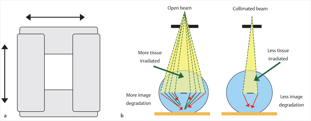
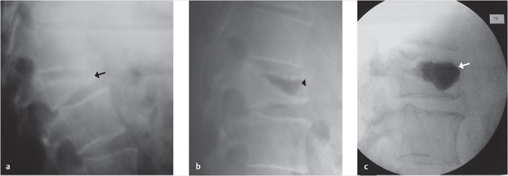
The fluoroscopic last-minute hold allows the provider to save the last image on the screen (▶Fig. 35.4). For example, if you save the anteroposterior (AP) view as you reach the medial cortex, then rotate to the lateral view and it shows the access needle is not in the vertebral body, the AP image information displayed can be used to determine if there is enough room medial to the pedicle to advance. Additionally, the last image hold can display the lateral view before injecting cement to see densities already present prior to cement injection, for example, a calcified aorta or a radiopaque material within the colon will be visually documented prior to injection so as not to confuse these densities with cement extravasation. Collimation of the X-ray beam will decrease scatter by decreasing the number of electrons passing through the X-ray tube and will also improve the image (▶Fig. 35.5, ▶Fig. 35.6, and ▶Fig. 35.7).
Fig. 35.4 Anteroposterior view of the thoracolumbar junction showing bilateral vertebral augmentation needles placed via a transpedicular approach and the good-quality image obtained by using the last image hold.
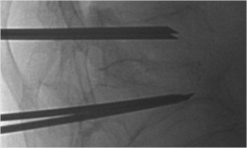
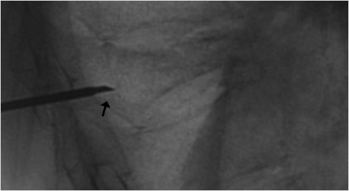
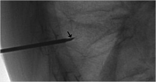
When high-grade fractures require precise trajectories, use a bevel needle to drive the access to the vertebral body. The bevel point up will drive the needle tip upward, bevel point down will drive the needle tip downward, bevel point medial will drive the needle tip toward the center, and bevel point lateral will drive the needle tip lateral (▶Fig. 35.8 and ▶Fig. 35.9). This is especially helpful when you need room to pass by the medial wall of the pedicle if you are close to the medial cortex.
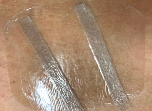
Leaving a transparent film dressing on the wound will allow the patient’s caretaker to monitor for bleeding, swelling, and infection while maintaining a sterile environment under the transparent film dressing (▶Fig. 35.10).
Fig. 35.5 Lateral view of the thoracolumbar junction showing vertebral augmentation needles placed into the T12 and L1 vertebral bodies. This image was obtained by using live fluoroscopy.
Fig. 35.6 Lateral fluoroscopic view showing two needles in the L1 vertebral body and calcification in the aorta as captured with the last image hold function.
Fig. 35.7 The collimator consists of shutters that move to provide a geometric limitation to the X-ray field and can be either circular or rectangular in shape (a). The collimation serves to limit the amount of radiation to the patient and this also produces less X-ray scatter and associated image degradation (b).
Fig. 35.8 Lateral X-ray view of the thoracolumbar junction shows the needle entering the vertebral body with the bevel tip (black arrow) directed down. The needle tip will then move in a downward trajectory.
Fig. 35.9 Lateral X-ray view of the thoracolumbar junction shows the needle entering the vertebral body with the bevel tip (black arrow) directed up. The needle tip will then move in an upward trajectory.
Fig. 35.10 Photograph of the patient’s lumbar kyphoplasty wound with Steri-strips and a film dressing in place.
35.3 Excellence is a Habit
Derrick D. Wagoner
“We are what we repeatedly do. Excellence, then, is not an act, but a habit.”
–Will Durant
We have the privilege of offering a treatment to patients that nearly immediately alleviates the agony they are experiencing and simultaneously restores the functionality lost secondary to their ailment. We must remember to put the patient first. Time and again, patients are not offered interventional treatment for vertebral fractures given that many fractures do not require treatment. This is true. There are many vertebral fractures that are not terribly painful and do not limit a patient’s function. The question concerning whether a fracture requires treatment is centered on one question. How much pain is the patient in? If the patient is in severe pain, their functionality is sure to be diminished. Waiting to see if your patient will either spontaneously “heal” or remain bedbound in a back brace, potentially developing pneumonia in the next 4 to 6 weeks, should not be contemplated. The benefits of the treatment far outweigh the risks.
35.4 Osteonecrosis of the Spine (Kümmel–Verneuil Disease)
Stephan Becker
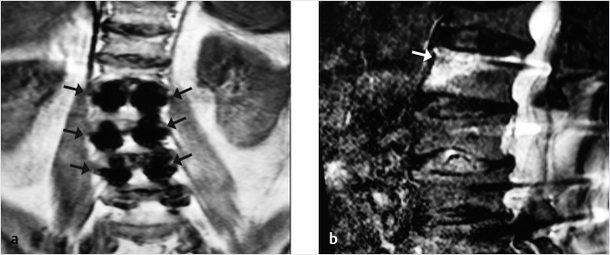
Osteonecrosis (ON), vascular necrosis, pseudarthrosis, and Kümmel’s spondylitis1–12 are descriptions of severe complications of a vertebral osteoporotic fracture (VOF). It has been discussed that disruption of anterior perforating vessels results in pseudarthrosis of the vertebra; hence, ON is mostly located at the anterior aspect of the vertebra (▶Fig. 35.11). In addition to a VOF, malignancy, infection, radiation therapy, liver cirrhosis, alcoholism, steroid treatments, sarcoidosis, hemoglobinopathies such as sickle cell anemia, Cushing’s syndrome, Gaucher’s syndrome, and dysbarism after diving accidents can also lead to ON.1,4,10–12 Nevertheless, osteoporosis and a fracture are by far the main causes for developing ON. This pathology bears typical changes on X-ray and MR imaging.13–17 On X-ray or CT, we typically find an intravertebral cleft, also described as a “gas sign” demonstrating fluid and/or gas in the vertebral body.14,17 On MRI, we find fluid or gas in the vertebral body, which can be seen as a dark or bright zones on T1 and T2/short tau inversion recovery (STIR) depending on what is present within the cleft.6,8,14,17
In typical cases of ON, no bone healing occurs, and the risk of severe kyphosis and compression of the dorsal neural structures increases massively. This disease may be missed if only standing X-rays are performed; therefore, it is indicated to perform a prone or supine X-ray, which can help in making the appropriate diagnosis.
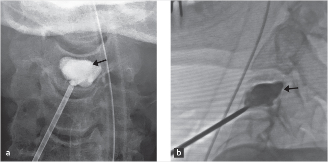
Nonsurgical treatment is not indicated to avoid plegic complications. In the past, vertebroplasty and balloon kyphoplasty (BKP) have been performed. Both techniques have led to severe bone resorption, collapse, and cement dislocation with ON, but this is seen more commonly with BKP (▶Fig. 35.12). It is known that cement filling after BKP and all other bone displacement vertebral augmentation procedures lead to stress shielding of the vertebra and increased resorption in the portions of the vertebral body not affected by the fracture, so it is thought that BKP and other procedures like it should be avoided in ON.18–21 Stress-shielding phenomena have not been found in vertebroplasty.18,19
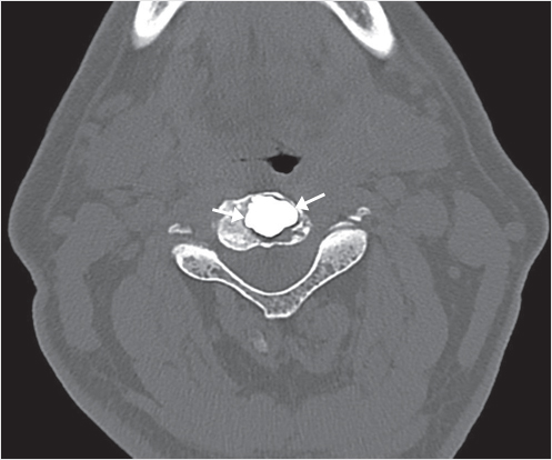
In order to achieve a good cement fill and interdigitation, vertebroplasty in cases of ON should be performed by experienced practitioners. New bone-preserving kyphoplasty procedures using implants such as the Kiva implant or the SpineJack have, so far, not resulted in cement dislocation and might be indicated to achieve good stabilization of the vertebral body without increased stress shielding and an increased risk of cement dislocation (▶Fig. 35.13).
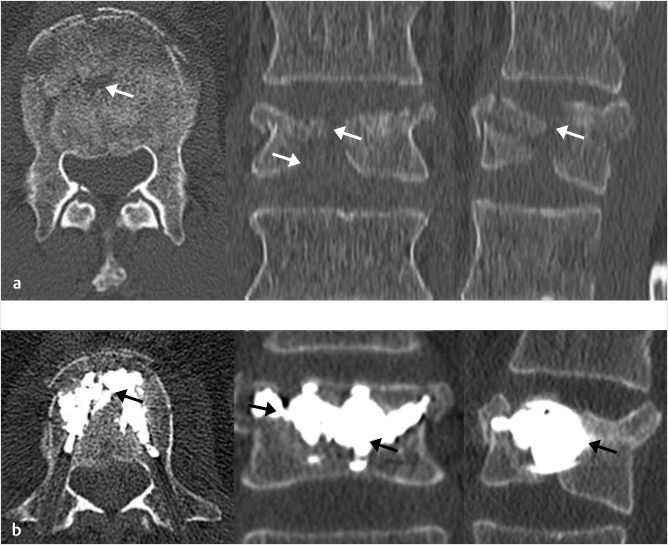
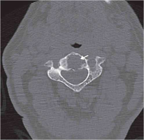
Fig. 35.11 Axial (a) and sagittal reconstruction (b) images from a CT scan in a patient with a T12 vertebral compression fractures show evidence of osteonecrosis with gas (black arrows) present within the anterior portion of the vertebral body. This is a typical location for the intravertebral gas.
Fig. 35.12 Lateral X-rays (a, b) and a lateral fluoroscopic image (c) in a 72-year-old man show a vertebral compression fracture that is severely collapsed when the patient is in a standing position (black arrow in a) that reduces and fills with air (black arrowhead in b). After vertebral augmentation, there is a normal cement fill within the vertebral cleft (white arrow in c). Six weeks after vertebral augmentation, there has been bone resorption around the cement (black arrowheads in d) and 10 weeks after augmentation, there is further bone resorption (black arrowheads in f) along with a now clearly defined adjacent-level vertebral fracture of D11 (black arrows in e and f).
Fig. 35.13 Standing lateral X-ray view in a 70-year-old man shows a severely compressed vertebral fracture at L1 (black arrow in a). Lateral and anteroposterior X-rays show the lumbar spine post-op after placement of a Kiva implant and polymethyl methacrylate (white arrows in b and c). After 12 weeks, there has been no discernible bone resorption (black arrowheads in d and e) or adjacent-level fracture (black arrow in d) after Kiva placement.
References
[1] Chou LH, Knight RQ. Idiopathic avascular necrosis of a vertebral body. Case report and literature review. Spine 1997;22(16):1928–1932
[2] Hasegawa K, Homma T, Uchiyama S, Takahashi H. Vertebral pseudarthrosis in the osteoporotic spine. Spine 1998;23(20):2201–2206
[3] Huy MD, Jensen ME, Marx WF, Kallmes DF. Percutaneous vertebroplasty in vertebral osteonecrosis (Kümmell’s spondylitis). Neurosurg Focus 1999;7(1):e2
[4] Ito M, Motomiya M, Abumi K, et al. Vertebral osteonecrosis associated with sarcoidosis. Case report. J Neurosurg Spine 2005;2(2):222–225
[5] Jang JS, Kim DY, Lee SH. Efficacy of percutaneous vertebroplasty in the treatment of intravertebral pseudarthrosis associated with noninfected avascular necrosis of the vertebral body. Spine 2003;28(14):1588–1592
[6] Maheshwari PR, Nagar AM, Prasad SS, Shah JR, Patkar DP. Avascular necrosis of spine: a rare appearance. Spine 2004;29(6):E119–E122
[7] Murakami H, Kawahara N, Gabata T, Nambu K, Tomita K. Vertebral body osteonecrosis without vertebral collapse. Spine 2003;28(16):E323–E328
[8] Van Eenenaam DP, el-Khoury GY. Delayed post-traumatic vertebral collapse (Kummell’s disease): case report with serial radiographs, computed tomographic scans, and bone scans. Spine 1993;18(9):1236–1241
[9] Young WF, Brown D, Kendler A, Clements D. Delayed post-traumatic osteonecrosis of a vertebral body (Kummell’s disease). Acta Orthop Belg 2002;68(1):13–19
[10] Allen BL Jr, Jinkins WJ III. Vertebral osteonecrosis associated with pancreatitis in a child. A case report. J Bone Joint Surg Am 1978;60(7):985–987
[11] Brower AC, Downey EF Jr. Kümmell disease: report of a case with serial radiographs. Radiology 1981;141(2):363–364
[12] Hutter CD. Dysbaric osteonecrosis: a reassessment and hypothesis. Med Hypotheses 2000;54(4):585–590
[13] Lieberman IH, Dudeney S, Reinhardt MK, Bell G. Initial outcome and efficacy of “kyphoplasty” in the treatment of painful osteoporotic vertebral compression fractures. Spine 2001;26(14):1631–1638
[14] Maldague BE, Noel HM, Malghem JJ. The intravertebral vacuum cleft: a sign of ischemic vertebral collapse. Radiology 1978;129(1):23–29
[15] Van Bockel SR, Mindelzun RE. Gas in the psoas muscle secondary to an intravertebral vacuum cleft: CT characteristics. J Comput Assist Tomogr 1987;11(5): 913–915
[16] Bhalla S, Reinus WR. The linear intravertebral vacuum: a sign of benign vertebral collapse. AJR Am J Roentgenol 1998;170(6):1563–1569
[17] McKiernan F, Faciszewski T. Intravertebral clefts in osteoporotic vertebral compression fractures. Arthritis Rheum 2003;48(5):1414–1419
[18] Becker S. The impact of cement stiffness, bone density and filling volume after balloon kyphoplasty and the risk of stress shielding on adjacent vertebral fractures. Osteoporos Int 2010;21(Suppl 1):118–119
[19] Dabirrahmani D, Becker S, Hogg M, Appleyard R, Baroud G, Gillies M. Mechanical variables affecting balloon kyphoplasty outcome: a finite element study. Comput Methods Biomech Biomed Engin 2012;15(3):211–220
[20] Krüger A, Oberkircher L, Kratz M, Baroud G, Becker S, Ruchholtz S. Cement interdigitation and bone-cement interface after augmenting fractured vertebrae: a cadaveric study. Int J Spine Surg 2012;6(1):115–123
[21] Rohlmann A, Boustani HN, Bergmann G, Zander T. A probabilistic finite element analysis of the stresses in the augmented vertebral body after vertebroplasty. Eur Spine J 2010;19(9):1585–1595
35.5 Cement Augmentation
Majid Khan
Percutaneous vertebroplasty (PVP) is widely used in the management of osteoporotic vertebral compression fractures (VCFs), but there are reported cases where a patient’s symptoms show partial response with change in the nature of pain. Upon referral to our institution, we revisited the imaging on such cases and found in some cases to have either too little cement deposition or, more frequently, uneven cement distribution only on one side of the treated vertebrae.
The author has found in his practice that a salvage procedure after failure of an improperly used technique can be quite beneficial to some patients and can help prevent open surgical intervention. Proper patient selection using both clinical and imaging findings is critical and it should be remembered that all patients may not be suited for repeat vertebroplasty.
PVP may be done using a unipedicular or bipedicular approach for cement injection with straight or curved needles. Regardless of needle type, the cement should be placed in the midline with adequate and uniform cement deposition. In certain cases with improperly performed techniques, we do see patients with uneven cement distribution or a small amount of cement within the vertebral body. Injection using a bipedicular technique tends to deliver a more uniform cement distribution more so than a unipedicular technique. When such vertebroplasty cases are deemed failure of treatment, performing repeat salvage cement augmentation can be considered the first choice prior to open surgery, especially for patients in whom the unipedicular approach was initially used.
Bone cement is introduced via the pedicle on the side of the vertebral body with the least amount of cement for cement delivery into the nonfilled portion of the previously partially filled vertebral body. This will give rise to a more uniform cement distribution and will help in filling any previously unfilled fracture clefts. For patients in whom a bipedicular approach was initially used, repeat vertebroplasty is technically more difficult, but usually the pedicle size is sufficient enough so a repeat augmentation can still be performed. At times, a small pedicle may necessitate the use of a small gauge access cannula and delivery port in order to properly access the vertebral body. At higher levels in the spine, especially in the thoracic spine, a parapedicular approach can be used.
The author’s clinical practice is primarily focused around treatment of pathological osteolytic compression fractures with all types of cases including metastatic disease with a complete breach of the vertebral cortices including the posterior vertebral body wall.
Cement filling of pathologically fractured vertebral body is very different from filling an osteoporotic VCF as benign fractures usually have a fill pattern that is homogeneous where a cement ball is seen to form at the point of injection, which grows in size as more cement is injected and is ultimately seen to fill the anterior and middle portions of the vertebral body as the injection is observed under constant fluoroscopic imaging. In severe osteolytic pathologically fractured vertebra, the initial cement injection shows cement spreading toward channels of least resistance and can be seen darting toward the breached posterior cortex. If this happens, the operator may have to stop the injection as extravasation into the spinal canal can lead to neurologic injury and the result of limiting the amount of cement can sometimes produce inadequate stabilization of the vertebral body.
35.5.1 Pearls
Inject contrast into the vertebral body before cement delivery to get a good idea about channels of least resistance. Based on what is seen on the injection of contrast, the tip of the delivery port can be extended more anteriorly or into another location within the vertebral body. If another appropriate location cannot be accessed with the initial straight needle, a curved needle can be used for delivery of cement to a different location.
After cement is seen extending into the posterior third of the vertebral body or noted to abut the breached cortex of any vertebral wall, the author usually waits for 2 to 3 minutes, which lets the cement to harden a bit and this hardened cement can serve as a barrier to unwanted cement extension. This technique can help more cement to be deposited into appropriate areas within the vertebral body.
35.6 Tips and Techniques of Vertebral Augmentation
Thomas Guido Andreshak and Edward Yoon
35.6.1 Cementing Tips after Prior Vertebral Augmentation
During vertebroplasty or vertebral augmentation in patients with compression fractures, inadequate cement fill will lead to fracture extension, collapse, or result in nonunion clefts. Using slow and low-pressure cement injection with thick cement is key to a successful cement fill. The bone filling cannula needs to be placed in the middle of the cement ball and it is imperative to obtain stability of the vertebral fracture by adding cement to the fracture clefts and the load-bearing portion of the vertebral body between the pedicles.
When reaugmenting a previous vertebroplasty or vertebral augmentation, an en face view may be used to visualize the pedicle outline and the upper vertebral margins. A transpedicular or parapedicular approach can be utilized to reaccess the vertebral body. Kambin’s triangle offers access to the superior end plate in order to obtain a sufficiently medial trajectory of the cannula and to avoid the neural canal and the nerve root. The use of a smaller (10- to 11-gauge) cannula is recommended for revision augmentation. The operator needs to be certain that there are no new subjacent fractures and if there is no significant postprocedural pain relief, continued fracture due to an unfilled cleft, collapse of the vertebral body, or fracture around the cement needs to be suspected. Upright lateral X-rays can be used to visualize significant vertebral body collapse and any positional change of height. A computed tomography (CT) scan can also demonstrate vacuum clefts and fissures. Magnetic resonance (MR) imaging or bone scan can also be used to assess for postoperative complications if these are suspected. CT may also be used and can be used to assess the adequacy of the cement fill in regard to filling the fracture clefts and stabilizing the overall structure of the vertebral body.
35.6.2 Kyphoplasty and Revision of L3 Pedicle Screw after Posttraumatic Screw Displacement
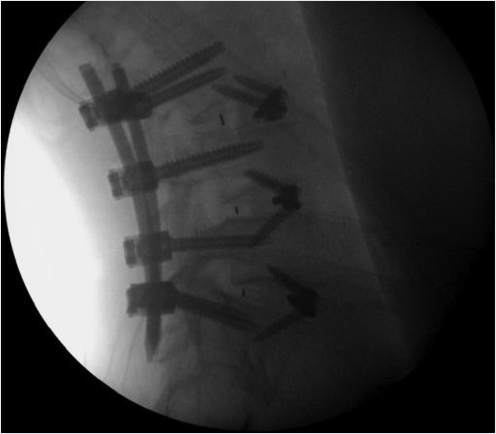
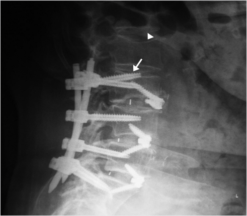
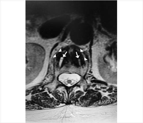
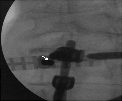
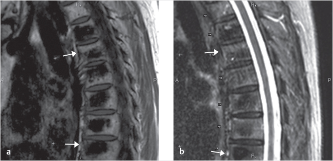
A 78-year-old woman with past medical history of primary osteoporosis and frequent falls as well as loss of balance due to spinal stenosis and scoliosis had a L3–S1 spinal fusion 4 weeks priorto a fall (▶Fig. 35.14). The patient presented with new and increasing back pain different in nature from the surgical pain and proximal to the incision. A lateral radiograph demonstrated osteoporotic vertebral compression fractures of L2 and L3 with the left L3 pedicle screw dehiscent superiorly into the L2–L3 intervertebral disk (▶Fig. 35.15). Sagittal short tau inversion recovery (STIR) and postcontrast T1-weighted MR images demonstrated vertebral body linear signal abnormalities typical of that of a vertebral fracture of L2 and an end plate fracture of L3 (▶Fig. 35.16).
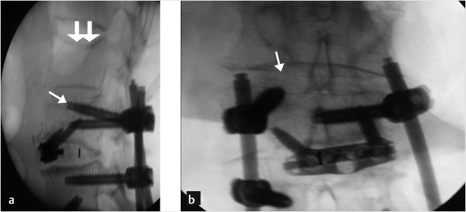
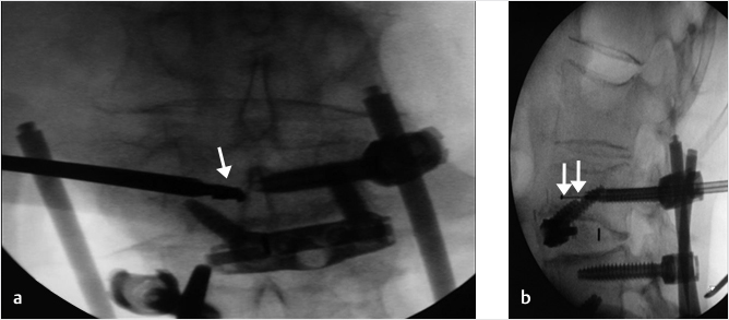
A decision was made to perform a balloon kyphoplasty of L2 to treat the vertebral compression fracture above the construct and at L3 to treat the vertebral fracture as well as to restabilize the dehiscent hardware (▶Fig. 35.17). A drill was directed through the left L3 pedicle away from the superior end plate and a balloon tamp was then placed in the center of the left side of the vertebral body (▶Fig. 35.18) The balloon tamp was inflated and a right-sided one-step introducer was also placed via a parapedicular approach (▶Fig. 35.19). A drill was then advanced through the introducer into the center of the vertebral body, adjacent to the inflated left-sided balloon (▶Fig. 35.20). Attention was then turned to the L2 vertebral body with bilateral transpedicular right and left balloon tamps placed and inflated. The right-sided L3 drill was placed without a balloon following the drill placement due to the risk of balloon rupture if it came in contact with the contralateral pedicle screw (▶Fig. 35.21). Polymethyl methacrylate injection was then performed at the L2 and L3 levels with cement filling the voids (▶Fig. 35.22). Final images demonstrated no leakage or extravasation of cement (▶Fig. 35.23).
Fig. 35.14 Lateral radiograph demonstrating spinal fusion with pedicle screw and rod augmentation and interbody fusions from L3-S1 without complications.
Fig. 35.15 Lateral radiograph demonstrating osteoporotic vertebral compression fractures of L2 (white arrowhead) and L3 with the L3 pedicle screw dehiscent superiorly into the L2-L3 intervertebral disk space (white arrow).
Fig. 35.16 Sagittal short tau inversion recovery (STIR) (a) and post contrast T1-weighted (b) sagittal images demonstrating a linear signal abnormality within the L2 vertebral body (white arrows in a and b) and a superior endplate deformity of L3 (white arrowheads in a and b) indicative of vertebral compression fractures of L2 and L3.
Fig. 35.17 Intraoperative lateral (a) and anteroposterior (b) fluoroscopic images demonstrating an L2 compression fracture (thick white arrows in a) and a compression fracture of L3 with the pedicle screw protruding into the L2-3 disk space (thin white arrows in a and b).
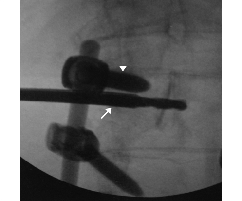
Fig. 35.18 Anteroposterior (a) fluoroscopic image showing a drill (white arrow) being directed through the left L3 pedicle and away from the superior endplate. Lateral (b) fluoroscopic image demonstrates a balloon tamp being placed in the center of the left side of the vertebral body (white arrows in b).
Fig. 35.19 Lateral (a) and anteroposterior (b) fluoroscopic images showing the balloon inflated creating a bone void (thin white arrows in a and b). A right sided one-step introducer was also placed via a para-pedicular approach (thick white arrows in a and b).
Fig. 35.20 Lateral fluoroscopic images demonstrate a drill (thick white arrows) being advanced through the para-pedicular introducer (thin white arrow) and into the vertebral body. The inflated left sided balloon is also seen (white arrowheads).
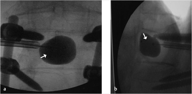
Fig. 35.21 Anteroposterior (a) and lateral (b) fluoroscopic images demonstrate right and left balloon tamps inflated at the level of L2 (circles). The right sided L3 drill (thin white arrows in a and b) was initially placed but no balloon was used at this location due to the risk of balloon rupture if it inflated against the contralateral pedicle screw.
Fig. 35.22 Lateral (a) and anteroposterior (b) fluoroscopic images show cement filling the voids of L2 and L3 (area within the white circles).
Fig. 35.23 Final images at the end of the procedure showing no leakage or extravasation of cement and optimal placement of the left L3 pedicle screw (white arrows in a and b).
35.6.3 Treating Recurring Fractures after Vertebroplasty
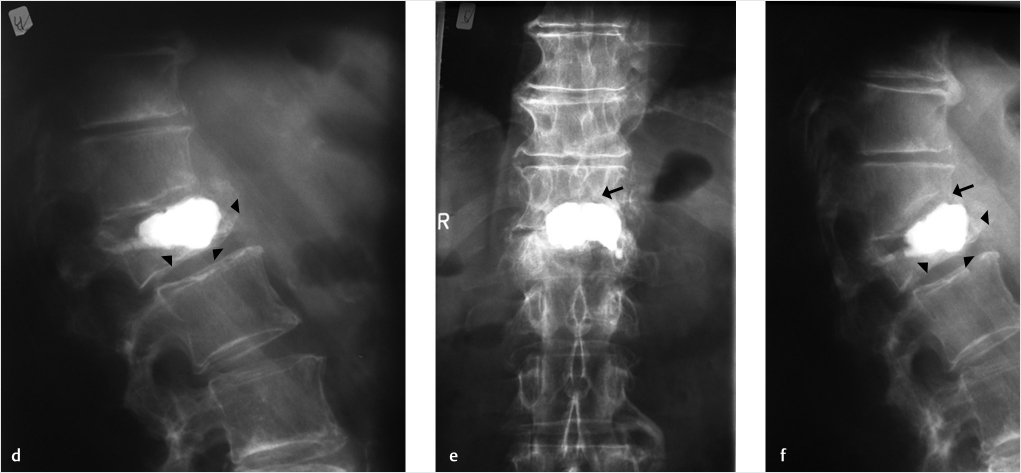
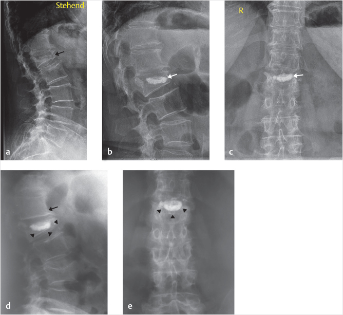
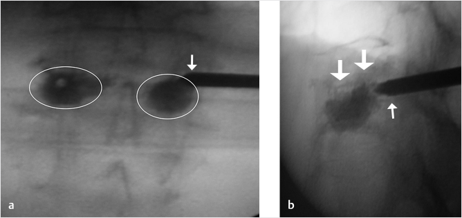
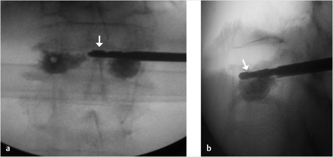
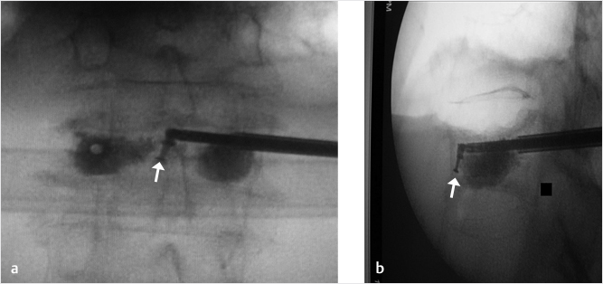
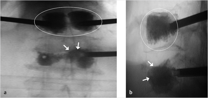
A 74-year-old woman with primary osteoporosis and superimposed secondary osteoporosis due to oral steroids presents with postprocedure pain in the lumbar region. The patient had prior vertebroplasty of T6 in 2012 and a subsequent vertebroplasty at T11 (▶Fig. 35.24) with balloon kyphoplasty of L2 in 2013. Further depression of L2 superior end plate with minimal cement volume was seen (▶Fig. 35.25). A decision was made to reaugment the L2 vertebral body using a drill, an inflatable bone tamp (IBT), a bone curet, and hydroxyapatite cement (▶Fig. 35.25, ▶Fig. 35.26, ▶Fig. 35.27, ▶Fig. 35.28).
A unilateral parapedicular approach was used to gain access to the superior aspect of the vertebral body at the site of the recurring collapse (▶Fig. 35.25). A drill was used to gain access to the site of collapse (▶Fig. 35.26) superior to preexisting cement and inferior to the collapsed superior end plate. A curet was inserted toward the superior and anterior portion of the central vertebral body for the purpose of directing the balloon expansion to the correct position (▶Fig. 35.27). Then the balloon was expanded at the superior aspect of the anterior and central vertebral body in the location previously treated by the curet (▶Fig. 35.28). The cement filled the void created and supported the superior end plate of L2 (▶Fig. 35.29). In addition, kyphoplasty of the L1 vertebral body was also performed due to the fracture, which was only seen on the MRI (▶Fig. 35.29). The patient reported a 90% pain relief and was discharged from the hospital the next day.
Fig. 35.24 Lateral radiograph demonstrates vertebroplasties of T6 and T12 (white arrows).
Fig. 35.25 (a) Anteroposterior and (b) lateral fluoroscopic views demonstrating reaugmentation needle (thin white arrows) access of the vertebral body with cement from prior augmentation at L2s (circles in a). There is minimal cement volume with recurring collapse (thick white arrows in b).
Fig. 35.26 (a) Anteroposterior and (b) lateral fluoroscopic views demonstrating a parapedicular approach using drill (white arrows in a and b) at the superior aspect of the cement just inferior to the collapse of the superior end plate of L2.
Fig. 35.27 (a) Anteroposterior and (b) lateral fluoroscopic views demonstrating a curet (white arrows in a and b) inserted toward the central and anterior portion of the superior vertebral body for the purpose of directing the balloon expansion to the correct position.
Fig. 35.28 (a) Anteroposterior and (b) lateral fluoroscopic views show the balloon expanded at the superior and anterior aspect of the central vertebral body (white arrows in a and b) in the location previously treated by the curet.
Fig. 35.29 (a) Anteroposterior and (b) lateral fluoroscopic views demonstrate the cement filling the previously created void (white arrows in a and b). A balloon kyphoplasty was also performed at the L1 level (circles in a and b) due to a fracture that was only seen on MRI.
35.6.4 Allowing for Access to Pedicle Screw Placement after Vertebral Augmentation
There are occasions where pedicle screws may need to be placed in the vertebral body after vertebral augmentation. In cases of lumbar spondylolisthesis and spinal stenosis, a decompression and fusion surgery may need to be performed at a later time. At junctional levels after fusion, it is common to need surgical decompression and fusion around previous levels of augmentation. Patients with osteoporosis may fracture around pedicle screws requiring revision. Regardless of the many reasons, it is optimal to be able to easily access a previous vertebral level that has undergone vertebral augmentation.
The technique of preserving the accessibility for pedicle screw placement uses a 4.2-mm (8-gauge) needle that allows one to use almost any spinal instrumentation system to fill the access hole with a 5.5-mm screw once the needle is removed from its position within the cement mass (▶Fig. 35.30). The technique involves initially placing the needles with an approach identical to that of pedicle screw placement. The needle placement is a bilateral transpedicular placement with the screws as parallel to the end plates as possible. Once the needles are placed and the vertebral augmentation is performed, the needles are left at least halfway into the vertebral body until the cement has sufficiently hardened. After the needles are removed, the needle tracks remain within the cement (▶Fig. 35.31 and ▶Fig. 35.32). This will allow for recannulation with a K-wire at a later time. The pedicle screw is then placed over the K-wire and screwed into an optimal position. This technique avoids the use of fenestrated screws, which can be difficult to use and allow for proximal junctional levels to be stabilized with hardware. Access to the vertebral body through the cement channel is typically preserved from months to years after the vertebral augmentation procedure.
Fig. 35.30 Anteroposterior fluoroscopic view of the L1 vertebral body showing a circular hole in the bone cement (white arrow).
35.6.5 Tips and Techniques of Vertebral Augmentation
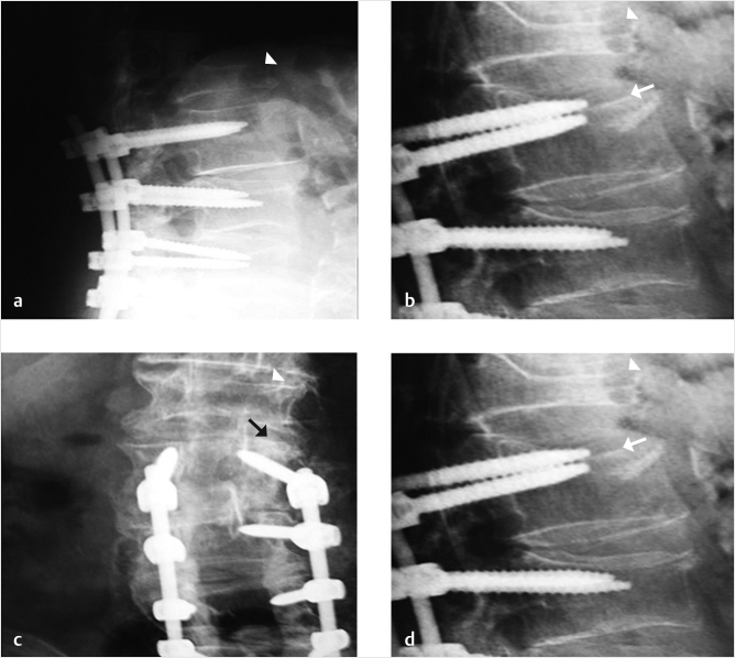
A 76-year-old man status postposterior lumbar fusion 2 months prior presented with lower back pain. A vertebral compression fracture was seen in the L2 vertebral body at the superior portion of the pedicle screw and rod construct with 25% compression of the L2 vertebral body in both the coronal and sagittal planes (▶Fig. 35.33). A cleft with partial reduction was also seen on sagittal STIR MR images (▶Fig. 35.34).
A size 3 IBT was selected after an en face view demonstrated that the inferior pedicle was sufficiently open to access the vertebral body (▶Fig. 35.35). A left-sided inferior transpedicular approach allowed for best positioning of the drill (▶Fig. 35.36), and a curet was used in aiding the appropriate balloon expansion by disrupting the bone preventing this expansion (▶Fig. 35.37). After the curettage, a balloon was placed into the vertebral body to support and reduce the fracture (▶Fig. 35.38). The left side was cemented well, but there was still inadequate cement placement with a unilateral approach (▶Fig. 35.39). Therefore, the right side was also cannulated with a similar technique. A drill was used to transverse to the cement bolus to ensure best position of the two cement mantles (▶Fig. 35.40). Subsequently, a balloon was used to create a void for the contralateral cement placement on the right with the cement filling the void and supporting the end plate/screw–bone junction (▶Fig. 35.41 and ▶Fig. 35.42).
The patient reported immediate pain relief with improved mobility and stopped using his walker. The patient was then able to care for the spouse who had recent surgery. Medical treatment using an anabolic bone agent for his underlying osteoporosis was also prescribed.
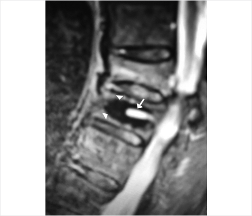
Fig. 35.31 Axial T2-weighted MR image showing needle tracks (white arrows) within the bilateral cement masses (white arrowheads).
Fig. 35.32 Sagittal short tau inversion recovery (STIR) MR image demonstrating a fluid-filled track (white arrow) within the cement mass (white arrowheads).
Fig. 35.33 Radiographs demonstrating 2-month postoperative lateral X-rays (a) and current films (b) with back pain onset. Pathologic vertebral fracture is seen with 25% compression (white arrows in b and d). Note coronal (black arrow in c) and sagittal (white arrows in b and d). A chronic L1 fracture is also noted (white arrowheads).
Fig. 35.34 (a) Coronal T1-weighted and (b) sagittal short tau inversion recovery (STIR) images demonstrating the pedicle screw and rod construct (black arrows in a) as well as the fracture cleft (white arrow in b) and partial reduction with supine positioning for MRI compared to upright lateral X-rays.
Fig. 35.35 Enface view demonstrating vertebral augmentation needle access of the inferior portion of the pedicle just inferior to the existing pedicle screw (white arrow). This portion of the pedicle was seen to be open to percutaneous needle access.
Fig. 35.36 Anteroposterior fluoroscopic image showing an inferior transpedicular approach with the drill (white arrow) passing inferior to the pedicle screw (white arrowhead) and into the center of the vertebral body.
Fig. 35.37 (a) Lateral and (b) anteroposterior fluoroscopic views show a curet (white arrows in a and b) inserted toward the anterior and contralateral vertebral body for the purpose of directing the balloon expansion to the correct position.
Fig. 35.38 (a) Anteroposterior and (b) lateral fluoroscopic views show the balloon expanded concentrically in midportion of the vertebral body (white arrows in a and b) and in the regions previously treated by the curet.
Fig. 35.39 (a) Lateral and (b) anteroposterior fluoroscopic views show cement in the mid to anterior portion of the vertebral body (area within the white circle in a) and that on the left side is cemented well (area within the white oval in b), but there is still inadequate cement on the right side with a left-side unipedicular approach (white arrows in b).
Fig. 35.40 Anteroposterior fluoroscopic images showing a drill (white arrow) traversing to the cement bolus using a similar approach on the right as was done previously on the left to access the right side of the vertebral body in preparation for deployment of the balloon.
Fig. 35.41 (a) Lateral and (b) anteroposterior fluoroscopic views show an inflated balloon (white arrows in a and b) that is creating a void for the contralateral cement injection.
Fig. 35.42 (a) Anteroposterior and (b) lateral fluoroscopic views show the cement filling the void (white arrows in a) and supporting the end plate and screw–bone junction (white arrowheads in b).
35.7 Radiofrequency Ablation and Vertebral Implant Augmentation in a Patient with Lytic Metastatic Disease
Bassem Georgy
A 63-year-old man presented with back pain from metastatic lung disease to the spine. Multiple lesions were seen throughout the thoracolumbar spine and the preoperative computed tomography (CT) examination showed relatively well-defined lytic lesions at the T12 and L1 levels. The T12 lesion involved the left half of the vertebra and the L1 lesion involved the anterior two-thirds of the vertebral body (▶Fig. 35.43, ▶Fig. 35.44, ▶Fig. 35.45). The patient had severe pain to closed-fist percussion at the thoracolumbar junction level on physical examination. Vertebral augmentation was requested for stabilization and pain control. Due to the focal nature of the disease, a radiofrequency ablation of the lesions was first performed using the STAR ablation device (Merit Medical, South Jordan, UT, United States). Ablation was performed using a unipedicular access on both levels for average of 8 minutes at each level (▶Fig. 35.44). The access cannula was then exchanged over a Kirschner wire and a Kiva implant (Benvenue Medical, San Jose, CA, United States) was deployed in the center of the ablated lesions (▶Fig. 35.45a, b). Postprocedure CT images show well-placed implants in the center of the lesions with minimal amount of cement injected and no leakage (▶Fig. 35.46a–d).
Fig. 35.43 Sagittal computed tomography (CT) reconstruction (a) shows lytic metastases involving the T12 and L1 vertebral bodies (white arrows in a). Axial CT images also the lytic lesions that involve the left vertebral body of T12 (white arrow in b) and the anterior portion of the L1 vertebral body (black arrows in c).
Fig. 35.44 Anteroposterior fluoroscopic image shows a radiofrequency ablation device placed via a unilateral transpedicular right sided approach.
Fig. 35.45 Anteroposterior (a) and lateral (b) fluoroscopic images show Kiva implants in the T12 and L1 vertebral bodies (white arrows in a and b).
Fig. 35.46 Axial (a and b) CT images along with sagittal (c) and coronal (d) CT reconstruction images show Kiva implants and bone cement (white arrows) within the lytic metastatic foci (white arrowheads).
35.8 Vertebral Hemangioma Causing Congestive Myelopathy Despite Absence of Angiographically Evident Arteriovenous Shunting
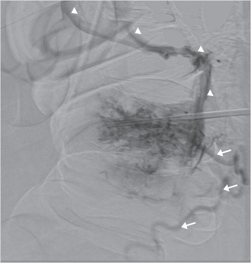
John D. Barr and Marco C. Pinho
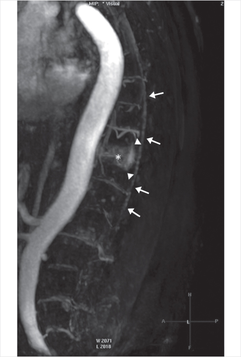
A 70-year-old man presented with a 2-month history of progressive lower extremity motor and sensory loss, inability to ambulate, and incontinence. Outside magnetic resonance (MR) imaging demonstrated abnormally increased T2 spinal cord signal intensity (SI) and multiple flow voids surrounding the distal spinal cord, as well as a large vertebral hemangioma at T10 (▶Fig. 35.47a, b). Imaging was suboptimal due to the patient’s very large body habitus (body mass index [BMI] 50). Complete spinal angiography did not demonstrate a dural arteriovenous (AV) fistula, as had been expected. Hypervascularity of the T10 hemangioma without AV shunting was noted (▶Fig. 35.48).
Dynamic contrast-enhanced MR angiography (MRA)performed the following day demonstrated early epidural venous plexus enhancement at the T10 level immediately preceding filling of abnormally dilated perimedullary veins (▶Fig. 35.49). Despite the absence of angiographically identified AV shunting, the MRA suggested that the large T10 hemangioma was the probable cause of AV shunting and spinal venous hypertension.
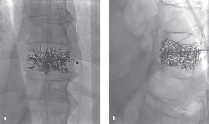
Embolization of the T10 hemangioma was done by a percutaneous transpedicular injection of 5.5 mL of Onyx 34 (Medtronic, Dublin, Ireland). This was performed under general anesthesia. Onyx embolization was selected rather than polymethyl methacrylate (PMMA) with consideration that any possible future surgical treatment might be complicated by the presence of the PMMA. Immediate pre-embolization bilateral T10 intercostal artery arteriograms and a percutaneous direct vertebrogram (▶Fig. 35.50) again revealed only vertebral hypervascularity with no AV shunting. Postembolization images and arteriograms confirmed extensive vertebral embolization with Onyx and minimal remaining hypervascularity (▶Fig. 35.51a, b); additional transarterial embolization was therefore felt to be unnecessary. Almost immediately upon awakening from general anesthesia, the patient reported improved lower extremity sensation. His symptoms significantly improved over the next month with recovery of limited ambulation and improved urinary continence.
Approximately 2 months after embolization, the patient began to experience worsening of his symptoms with regression to his pretreatment level by month 4. Repeat MR imaging and MRA again demonstrated persistent abnormal spinal cord SI, multiple flow voids, early T10-level epidural plexus enhancement, and dilated perimedullary veins. Successful transarterial embolization of the hemangioma via bilateral injections of the T10 intercostal arteries with a total of 4-mL Onyx 34 was performed (▶Fig. 35.52a, b); this was more difficult than usual because the Onyx already in place impaired visualization of the newly injected Onyx. Immediate pre-embolization bilateral T9–T11 intercostal artery arteriograms had again revealed only T10 vertebral hypervascularity with no AV shunting. The patient continued to decline neurologically with regression to paraplegia and incontinence, as well as worsening of the spinal cord swelling and edema on MR imaging. Open surgical corpectomy to definitively eliminate the residual AV shunting was deemed infeasible due to the very high risk posed by the patient’s large body habitus.
Fig. 35.47 Pretreatment T2-weighted sagittal MR imaging examination (a) shows increased distal spinal cord signal intensity (white arrows in a), extensive surrounding flow voids (white arrowheads), and a large T10 hemangioma (white circle). Curved coronal reformat (b) of balanced steady-state free precession (balanced fast field echo) better depicts the extensive network of tortuous, engorged veins (white arrows in b).
Fig. 35.48 Late arterial phase of sagittal contrast-enhanced MRA shows enlarged T10 intercostal arteries and hypervascularity of the T10 hemangioma (asterisk). Dynamic sequences showed early filling of the epidural venous plexus at T10 (arrowheads) and subsequent filling of perimedullary veins (long arrows).
Fig. 35.49 Selective left T10 intercostal arteriography (anteroposterior view) revealed only hypervascularity of the hemangioma (vessels within the white circle) without arteriovenous shunting.
Approximately 1 year later, the patient began to experience severe radiating mid-abdominal pain consistent with a T10 dermatomal distribution. His neurological status was otherwise unchanged. Repeat MR imaging and MRA demonstrated significant worsening of the spinal cord edema, now extending superiorly to the level of T3–T4 (▶Fig. 35.53a, b), and newly developed areas of patchy abnormal postcontrast enhancement along the lower thoracic spinal cord, permeated by nonenhancing necrotic foci, consistent with venous infarcts, complicating the chronic congestive myelopathy. Definitive elimination of the apparently persistent AV shunting was felt to be necessary to prevent progressive myelopathy with upper extremity impairment and, possibly, to relieve the new-onset radicular pain. Open surgical corpectomy was again deemed to have unacceptable risks.
Treatment options including radiofrequency (RF) ablation, RF ablation combined with PMMA augmentation, and stereotactic radiosurgery were considered. The latency period associated with radiosurgery was considered a negative factor, given the patient’s ongoing severe pain. Given that two embolization treatments had failed to adequately eliminate the AV shunting, we felt that RF ablation combined with PMMA augmentation would have the highest probability of success. We recognized, however, that visualization of PMMA during injection would be difficult and have increased risk of leakage into the spinal canal or neural foramen with the large amount of Onyx already in place. This increased risk was balanced by the fact that the patient had essentially already lost spinal cord function at and below the target level. The primary treatment goal was to prevent progressive ascending myelopathy. PMMA injection under CT guidance or cone beam CT was considered to allow more precise PMMA placement, but use of these modalities was precluded by the patient’s large body habitus.
Fig. 35.50 A T10 vertebrogram (lateral view) showed only epidural (white arrow) and central venous (white arrowheads) drainage from the hemangioma.
Seventeen months after initial treatment, the patient underwent T10 RF ablation under general anesthesia using the OsteoCool system (Medtronic, Dublin, Ireland). Immediately prior to the ablation, a vertebrogram was performed with no AV shunting demonstrated. After ablation, a total of 7 mL of PMMA was deliberately injected until very minimal filing of the epidural plexus was noted (▶Fig. 35.54a, b). The treatment goal was to devascularize and disconnect the hemangioma from the epidural plexus to the greatest extent possible.
The patient’s pain resolved almost immediately after the RF ablation and augmentation procedure. His neurological status has remained otherwise stable. MR imaging and MRA performed 5 months after the last procedure demonstrated resolution of the spinal cord edema, swelling, and enhancement, with development of atrophy and myelomalacia in the lower thoracic cord (corresponding to the location of the venous infarct), and only very minimal persistent AV shunting (▶Fig. 35.55a, b). This case is notable for the lack of AV shunting demonstrable by conventional catheter-based spinal angiography as well as by a direct vertebrogram. Although such shunting was evidenced by the abnormal intradural flow voids on MR imaging and dynamic MRA, no other cause for the dilated perimedullary veins was identified. That such apparently subtle AV shunting caused severe spinal cord venous hypertension was confirmed by the positive treatment responses following the first and third interventions and the near complete resolution of imaging abnormalities after the final intervention.
Fig. 35.51 Postpercutaneous embolization radiographs, posteroanterior (a) and lateral (b) views, show extensive permeation of the hemangioma with Onyx.
Fig. 35.52 Postarterial embolization radiographs, posteroanterior (a) and lateral (b) views, show further permeation of the hemangioma with additional Onyx.
Fig. 35.53 One year postarterial embolization MR imaging examination. A T2-weighted image in the sagittal plane (a) shows abnormally increased spinal cord signal intensity and swelling now extending to the upper thoracic level (white arrows). Postcontrast T1-weighted image (b) demonstrates areas of marked abnormal postcontrast enhancement in the conus (area within the white oval), with irregular hypoenhancing foci, consistent with venous infarction.
Fig. 35.54 Postradiofrequency ablation and augmentation radiographs, (a) posteroanterior and (b) lateral views, show extensive permeation of the hemangioma with polymethyl methacrylate and Onyx.
Fig. 35.55 Sagittal T2-weighted (a) and T1-weighted contrast-enhanced (a) MR images obtained 5 months after the final procedure demonstrated marked improvement of cord edema, swelling, and enhancement (white arrows in a), with development of atrophy and myelomalacia in the lower thoracic cord (area within the white oval). Dynamic MRA (b) showed only very minimal persistent arteriovenous shunting.
35.9 Vertebral Augmentation Devices in the Treatment of Traumatic Vertebral Fractures
Stefano Marcia
Vertebral trauma is a common condition that can give rise to both major and minor complications. Multiple classifications have been published in the past trying to establish stable and unstable fractures and surgical and nonsurgical fractures (see Chapter 2).1–4 Traumatic vertebral fractures can be defined as stable or unstable relative to the disruption of three or four columns. Although multiple classification systems exist within the literature, Magerl’s classification is the most commonly used and considers the type of injury to be divided into compression, rotation, and distraction injuries with multiple subtypes. There is increasing severity from A to C, and within each group, the severity usually increases within the subgroups from 0.1 to 0.2 to 0.3. All these pathomorphologies are supported by a mechanism of injury, which is responsible for the extent of the injury. The type of injury with its groups and subgroups is also able to suggest the treatment modality.
The management of traumatic spine fracture patients is well known and has been defined by many protocols (Chapter 2).5-8 An important factor is the presence or absence of associated clinical neurological symptoms such as myelopathy, motor deficit, and bladder or bowel dysfunction. The injury characteristic can be further defined by using diagnostic imaging resources such as X-ray, MRI, multidetector computed tomography (MDCT), or both MRI/MDCT, but treatment philosophies and strategies still differ significantly.
Magerl A1 type vertebral compression fractures (VCFs) represent the main indication for percutaneous vertebroplasty (PVP), percutaneous balloon kyphoplasty (BKP), or vertebral augmentation (VA), but these types of fractures can also be treated with orthotic devices, bed rest, as well as medical and/or physical therapy at least for 3 to 6 months. This nonsurgical management (NSM) is only marginally effective and cannot always mitigate the possibility of the VCF worsening with additional collapse and worsening of the kyphotic deformity. It should also be considered that orthotic bracing will also cause other problems such as cardiorespiratory diseases, sleep disorders, and gastrointestinal motility reduction.
Fracture types A1 and A2 (except for A2.3) are regarded as stable, while burst fractures and fractures involving the posterior wall, especially the higher rated A3.3 fractures that lack sufficient anterior column support, are designated as unstable. Flexion–distraction injuries as seen in the B1- to B3-type fractures are unstable. The highest degree of instability is seen in type C fractures, which are characterized by a rotational component. NSM is feasible in types A1, A2, and some lower rated A3 fractures. In these patients, axial alignment and bracing are done during an emergency department or hospital stay with subsequent mobilization and ambulation under the supervision of a physical therapist. Surgical intervention with secondary anterior vertebral replacement might be needed in A2.3 pincer fractures. Burst fractures (A3) are characterized by their incapability to withstand anterior load, which designates these fractures as unstable injuries. In A3 fractures, there is a high rate of unseen posterior injury, which, if present, can be an indication for posterior instrumentation.
According to AO principles (anatomic reduction: fracture reduction and fixation to restore functional anatomical relationships; stable fixation: stability by rigid fixation or splinting, as the specific type of the fracture and the injury requires; maintaining good blood supply: preservation of the blood supply to soft tissue and bone by careful handling and gentle reduction techniques; early mobilization: early and safe mobilization of the fractured part and the patient) and as an evolution and alternative to BKP, VA mechanical devices were introduced in last few years.9,10 These devices were developed to maximize long-term vertebral height restoration and to restore as much of the original anatomic alignment as possible. Clinical experience has demonstrated that one of the limitations of BKP was a loss of restored height after balloon deflation due to vertebral elastic recoil11 along with difficulty in treating A2 fractures because the vertebral split fractures were difficult to treat with the balloon that expanded centrifugally. Thanks to the capacity of certain implant VA devices to restore the physiologic vertebral height and to obtain a more homogeneous distribution of the cement with a better axial resistance to load, this treatment certainly has the capability of treating patients with more complex A2 and A3 fractures as well as the patient with less damaged Magerl A1 fractures. Due to the capacity of some VA devices to produce ligamentotaxis, the more complex burst fractures may be better reduced and the fracture fragments pulled together and stabilized. The most commonly used VA systems on the market are the following: Osseofix (Alphatec Spine Inc, Carlsbad, CA, United States), a titanium self-expandable mesh cage, Vertebral Body Stenting (VBS; Synthes, Soletta, Switzerland), a titanium balloon-expandable stent, Tektona (SpineArt, Geneva, Switzerland), a vertebral remodeling system, and the SpineJack (Vexim, Balma, France), a titanium endovertebral jack.
These procedures can be performed in an operating room equipped with a C arm or in an angiography room. Usually local anesthesia, moderate sedation, or deep sedation is used, but some surgeons prefer the use of general anaesthesia.9
All these implants require the same bipedicular approach, with the access cannulas inserted using the anteroposterior (AP) view or the oblique view and then advanced in the AP projection to the medial aspect of the pedicle. The medial margin of the pedicle as seen in the AP view is a very important anatomical landmark to check to make sure the needle is in the posterior portion of the vertebral body in the lateral view before advancing it farther into the vertebral body.
The OsseoFix12,13,17 mesh cage implant uses two Kirschner’s wires that are inserted into the access cannulas, followed by removal of the cannulas and insertion of the drill into the anterior third of the vertebral body. An implant delivery system helps insert the two titanium mesh cages. A mechanical actuation system is used to deploy the expandable cages in a controlled manner. The size of the cage is selected according to preoperative planning from preoperative CT scans. Cement injection is then performed by means of dedicated bone fillers. Although the conventional OsseoFix implant is used with cement, some authors described the implant of the mesh cages without PMMA injection.13
The VBS14,15,17 device represents an evolution of BKP, having a balloon-expandable CoCrWNi alloy stent that can be delivered with balloon inflation.14,15 Through the working cannula, a metallic drill can be used to access the anterior portion of the vertebral body and create a channel for the placement of the metallic implant. The drill is then removed and the mechanical system is inserted. The systems are connected and, under fluoroscopic guidance, the balloon is inflated and the stent is expanded. After implant deployment, the PMMA is injected into the cavity created by the balloon and the expanded stent. The cement can be injected through a slow injection system such as a bone filler or through 1-mL syringe. A high-viscosity cement is typically used to help prevent extravasation.
The introduction of the Tektona device requires the same bipedicular approach. After the inner cannula is removed, a blunt wire is introduced. Once the wire is in place, a metallic drill, preassembled with a working cannula, is used over the wire to access the anterior portion of the vertebral body. The drill is then disconnected from the working cannula and removed, and the Vertebral Fracture Reducer (VFR) mechanical system is then inserted through the working cannula. After VFR insertion, the expansion of the lamella can be performed by squeezing the handle. Fluoroscopic guidance is used to check the position of the lamella and the proper expansion until the desired fracture reduction is attained. Once the desired expansion has been achieved, the VFR instrument is removed, leaving the working cannula in place. The PMMA is then prepared and injected into the cavity. The bone cement is mixed with a dedicated mixing device and then injected through a cement filler under continuous fluoroscopic guidance. The bone fillers and the working cannulas are then removed.
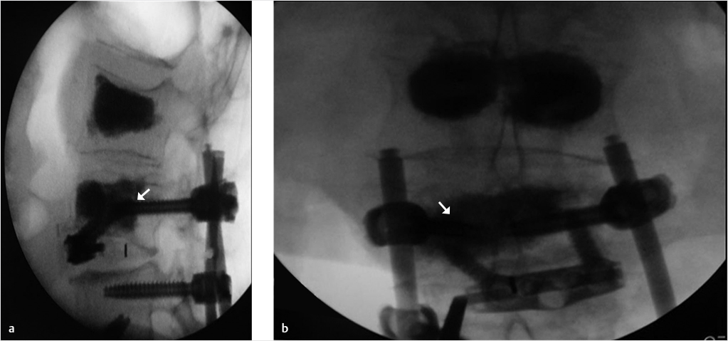
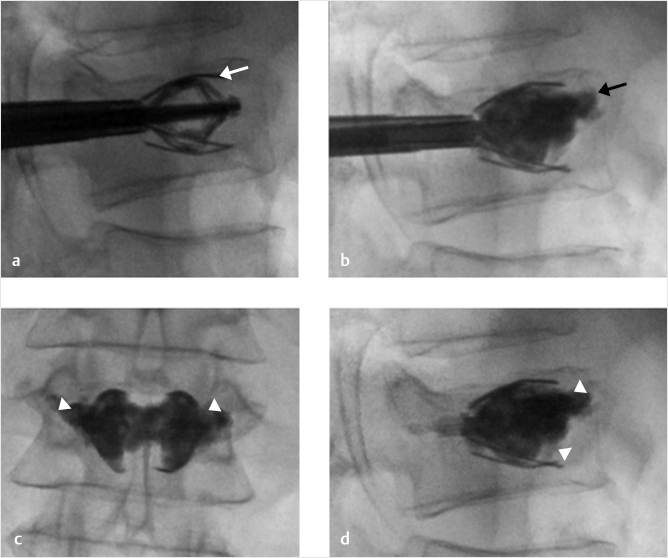
The concept of the SpineJack15–17 implant is different from the other VA systems in that there is a craniocaudal expansion of the device (instead of a spherical expansion that is seen in most other devices). This allows forces to be applied only on the vertebral end plates in a way that optimizes height restoration. Reduction of the bone fragments is also seen with this height restoration due to the ligamentotaxis that occurs with fracture reduction. After the trocar access needles are placed, a Kirschner wire is inserted. A manual cannulated reamer is then used to create the pathway for the template. The procedure is then repeated through the contralateral pedicle. The implants are then placed into the vertebral body and expanded with manual rotation of a multifunctional handle. The expansion of the implant produces fracture reduction and height restoration and provides mechanical support to the fractured vertebral body. Once the implants are delivered, the bone cement can be injected through dedicated bone fillers under fluoroscopic guidance (▶Fig. 35.56 and ▶Fig. 35.57). After all these procedures, the patients are kept for 2 to 3 hours in the hospital for clinical monitoring and then discharged.
All of the various devices available on the market have their own characteristics and method of reducing VCFs. Although most of these are effective in producing fracture reduction and stabilization of the vertebral body, the SpineJack seems to be the most suitable in the treatment of traumatic fractures, even A2 or A3 fractures as a standalone without any other posterior instrumentation.17
Fig. 35.56 Treatment of traumatic A3.3 fracture of L1 with the SpineJack device. The SpineJack is placed into the vertebral body and expanded (white arrow in a). Cement is then injected (black arrow in b) and the cannulas are removed, leaving an expanded SpineJack and cement (white arrowheads in c and d).
Fig. 35.57 Computed tomography exam taken before (a) and after (b) SpineJack placement. A Magerl A3.3 fracture is seen to have prominent comminution of the fracture (white arrows in a) and loss of vertebral body height. After placement of the SpineJack and injection of cement, the fracture fragments appear stable (black arrows in b) and the vertebral height restored.
References
[1] Magerl F, Aebi M, Gertzbein SD, Harms J, Nazarian S. A comprehensive classification of thoracic and lumbar injuries. Eur Spine J 1994;3(4):184–201
[2] Vaccaro AR, Lehman RA Jr, Hurlbert RJ, et al. A new classification of thoracolumbar injuries: the importance of injury morphology, the integrity of the posterior ligamentous complex, and neurologic status. Spine 2005;30(20): 2325–2333
[3] Denis F. The three column spine and its significance in the classification of acute thoracolumbar spinal injuries. Spine 1983;8(8):817–831
[4] Vaccaro AR, Oner C, Kepler CK, et al; AOSpine Spinal Cord Injury & Trauma Knowledge Forum. AOSpine thoracolumbar spine injury classification system: fracture description, neurological status, and key modifiers. Spine 2013;38(23):2028–2037
[5] Zhang L, Zou J, Gan M, Shi J, Li J, Yang H. Treatment of thoracolumbar burst fractures: short-segment pedicle instrumentation versus kyphoplasty. Acta Orthop Belg 2013;79(6):718–725
[6] Yi L, Jingping B, Gele J, Baoleri X, Taixiang W. Operative versus non-operative treatment for thoracolumbar burst fractures without neurological deficit. Cochrane Database Syst Rev 2006(4):CD005079
[7] Fuentes S, Blondel B, Metellus P, Gaudart J, Adetchessi T, Dufour H. Percutaneous kyphoplasty and pedicle screw fixation for the management of thoraco-lumbar burst fractures. Eur Spine J 2010;19(8):1281–1287
[8] Verlaan JJ, Dhert WJA, Oner FC. Intervertebral disc viability after burst fractures of the thoracic and lumbar spine treated with pedicle screw fixation and direct end-plate restoration. Spine J 2013;13(3):217–221
[9] Muto M, Marcia S, Guarnieri G, Pereira V. Assisted techniques for vertebral cementoplasty: why should we do it? Eur J Radiol 2015;84(5):783–788
[10] Filippiadis DK, Marcia S, Ryan A, et al. New implant-based technologies in the spine. Cardiovasc Intervent Radiol 2018;41(10):1463–1473
[11] Verlaan JJ, van de Kraats EB, Oner FC, van Walsum T, Niessen WJ, Dhert WJ. Bone displacement and the role of longitudinal ligaments during balloon vertebroplasty in traumatic thoracolumbar fractures. Spine 2005;30(16): 1832–1839
[12] Ender SA, Wetterau E, Ender M, Kühn JP, Merk HR, Kayser R. Percutaneous stabilization system Osseofix for treatment of osteoporotic vertebral compression fractures: clinical and radiological results after 12 months. PLoS One 2013;8(6):e65119
[13] Eschler A, Ender SA, Ulmar B, Herlyn P, Mittlmeier T, Gradl G. Cementless fixation of osteoporotic VCFs using titanium mesh implants (OsseoFix): preliminary results. BioMed Res Int 2014;2014:853897
[14] Hartmann F, Griese M, Dietz SO, Kuhn S, Rommens PM, Gercek E. Two-year results of vertebral body stenting for the treatment of traumatic incomplete burst fractures. Minim Invasive Ther Allied Technol 2015;24(3):161–166
[15] Kruger A, Oberkircher L, Figiel J, et al. Height restoration of osteoporotic vertebral compression fractures using different intravertebral reduction devices: a cadaveric study. Spine J 2015;15(5):1092–1098
[16] Noriega D, Maestretti G, Renaud C, et al. Clinical performance and safety of 108 spinejack implantations: 1-year results of a prospective multicentre single-arm registry study. BioMed Res Int 2015;2015:173872
[17] Vanni D, Galzio R, Kazakova A, et al. Third-generation percutaneous vertebral augmentation systems. J Spine Surg 2016;2(1):13–20
35.10 Vertebral Augmentation: Tips and Tricks
Wayne J. Olan
As we enter a new era in vertebral augmentation with fixation with the release of the SpineJack device from Stryker in the fall of 2018, the use of this product and being facile with the subtleties of its indications and performance will help maximize the benefit to both the operator and the patient and will ensure maximum clinical benefit when using this device.1
To maximize the benefit and the reduction with SpineJack, we are using a simple technique to make certain we take full advantage of the lifting power and reducing force of the device. Just prior to elevating the SpineJack, we take an anteroposterior (AP) image to the vertebral body with both SpineJacks in place and a wide enough field of view so we can see the bottom of the handles that hold the implant. Confirming that the base of the handles are parallel to the inferior end plates of the treating vertebral body assures the operator that when the device opens it will open perpendicular to the end plates and will contribute maximally to the most effective end plate elevation and subsequent vertebral body reduction. Remember, AP to the patient does not always mean AP to the vertebral body.
Reference
[1] A Prospective, Multicenter, Randomized, Comparative Clinical Study to Compare the Safety and Effectiveness of Two Vertebral Compression Fracture (VCF) Reduction Techniques: The SpineJack and the KyphX Xpander Inflatable Bone Tamp. The U.S. National Library of Medicine and Clinical Trials. gov Web site. https://clinicaltrials.gov/ct2/show/NCT02461810. Published May 1, 2018. Accessed October 31, 2018
35.11 Dorsal Root Ganglion Stimulation to Treat Persistent Radicular Pain after Compression Fracture
Timothy Deer
Dorsal root ganglion (DRG) stimulation was first reported in its current form in 2011 in a pilot study of 10 patients with chronic nerve pain. In recent years, this therapy has been approved for widespread use in the United States, Europe, and Australia for focal neuropathic pain. In the current literature, the use of DRG stimulation has not been reported to treat persistent nerve pain after vertebral fracture and subsequent kyphoplasty.
The patient was a 53-year-old woman who suffered a traumatic fracture of the L1 vertebrae during a rollover accident. The patient was treated successfully with vertebral augmentation kyphoplasty of the fracture that involved the vertebral body and had no obvious damage to the posterior elements or to the adjacent neural elements, but immediately postprocedure she developed severe burning bilateral foot pain. The MR imaging examination showed no compression or retropulsion, but the pain persisted and she eventually failed injections, physical therapy, anticonvulsants, and opioid therapy. She was subsequently referred to an interventional pain physician for neuromodulation.
The patient underwent bilateral S1 DRG stimulation under general anesthesia with neuromonitoring (▶Fig. 35.58). The trial resulted in 85% relief at day 10, and subsequently the patient underwent a permanent implant. At the 6-month follow-up, both the L1 area and her foot pain were well controlled, and the patient was back to full employment with no oral medications. This case shows potential solutions to postprocedure nerve irritation after the fracture is adequately stabilized, but the postoperative course is complicated by neuropathic pain.
Fig. 35.58 (a, b) Bilateral S1 DRG stimulation under general anesthesia with neuromonitoring.
35.12 Vertebral Augmentation Tips and Tricks of the Trade
Neal H. Shonnard
35.12.1 Thermally Accelerated Cement
Cement augmentation of vertebral compression fractures utilizes polymethyl methacrylate (PMMA) or bone cement. The cement cures and solidifies through a polymerization process that produces an exothermic reaction. Applying heat (▶Fig. 35.59) of approximately 120°F for 10 to 20 seconds to the cement immediately after mixing accelerates the polymerization process, increasing the viscosity of the cement. A thicker cement allows for better control over the distribution of the cement and lessens the frequency of cement leakage outside the vertebral body. Cement injection may be performed immediately after the cement is heated in a water bath and is observed closely under lateral fluoroscopic visualization.
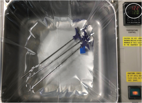
Fig. 35.59 Hot bath at 120°F (white circle) to enhance cement viscosity. The bone fillers with cement (white arrows) are placed in the water bath for 10 to 15 seconds.
35.12.2 Unipedicular Approach for Bilateral Cementation
A standard unilateral approach may be done through the ipsilateral pedicle or via a parapedicular approach. The introducer needle is placed into the vertebral body and then the drill is and inserted and angled to reach the midline in the anterior portion of the vertebral body (▶Fig. 35.60a, b). The curet is then introduced after removal of the drill (▶Fig. 35.61a), and is deployed toward the contralateral pedicle (▶Fig. 35.61b, c). The curet is pulled dorsally from the anterior vertebral body to the posterior third of the vertebral body (▶Fig. 35.62a, b). This technique is repeated while angling the curet toward the contralateral portion of the vertebral body until the curet reaches the location of the opposite pedicle on the anteroposterior view (▶Fig. 35.61c). The subsequent expansion of the balloon (▶Fig. 35.63a, b) will tend to conform to the location of the previous curettage and the cement will also flow into the cavities created by the curet and balloon (▶Fig. 35.64a, b).
35.12.3 Avoiding Wrong Level Surgery
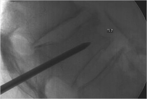
A reliable intraoperative X-ray technique for establishing the intended level of treatment utilizes a 14-gauge needle placed at the L2 level. The lumbar levels are counted proximally from the pelvis, using a 14-gauge needle at the pedicle of L2 as a reference point. The fluoroscopy is moved proximally to count the distal thoracic vertebral levels until the intended level(s) is reached (▶Fig. 35.65a, b). This technique is very helpful to identify nondisplaced mid- and proximal thoracic vertebral fractures and to avoid wrong level surgery.
Fig. 35.60 (a) Anteroposterior and (b) lateral fluoroscopic views of the mid-thoracic spine shows the drill angled to reach the midline (white arrow in a) in the anterior portion of the vertebral body (white arrow in b).
Fig. 35.61 Anteroposterior fluoroscopic views of the mid-thoracic spine shows the curet is then introduced after removal of the drill (white arrow in a), and is deployed toward the contralateral pedicle (white arrows in b and c; pedicle shown by black arrows in b and c).
Fig. 35.62 Lateral fluoroscopic views of the mid-thoracic spine shows the curet is pulled dorsally from the anterior vertebral body to the posterior third of the vertebral body (white arrows in a and b).
Fig. 35.63 (a) Anteroposterior and (b) lateral fluoroscopic views of the mid-thoracic spine show the expansion of the balloon (white arrows in a and b) in the location of the previous curettage.
Fig. 35.64 (a) Anteroposterior and (b) lateral fluoroscopic views of the mid-thoracic spine show adequate cement fill in the location of the cavities created by the curet and balloon (white arrows in a and b).
Fig. 35.65 Lateral fluoroscopic views of the lumbar spine (a) and the thoracolumbar junction (b) shows a 14-gauge needle just posterior to the pedicle at L2 (black arrow in a). A second needle is placed at the target level just posterior to T10 (black arrow in b).
35.13 Treatment of a Thoracic Vertebral Compression Fracture with Vertebra Plana
J. Dana Dunleavy
Included is a case of a thoracic vertebra plana. Interestingly, this underscores the importance of treating patients with compression fractures promptly since the fracture continued to progress in the interval between identification of the fracture and treatment.
Many practices do not treat thoracic compression fractures (and have even spread false information that lumbar augmentation provides clinical benefit but thoracic augmentation has no benefit) and do not treat vertebra plana or burst fractures because it is “unsafe.” The facts behind both of the above scenarios is that they are more technically challenging but just as important and just as helpful to treat and optimal results are very achievable and safe with proper planning and technique (▶Fig. 35.66, ▶Fig. 35.67, ▶Fig. 35.68, ▶Fig. 35.69, and ▶Fig. 35.70).
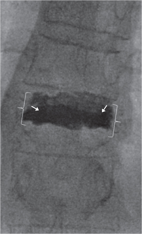
Pedicles are shorter and narrower and have a greater craniocaudal angulation in the thoracic spine as compared with the lumbar spine and therefore access needs to be more cranial than the planned level of augmentation. In the provided case, we used a Merit directional osteotome (Merit Medical Systems, Inc, South Jordan, UT) to gain intrapedicular access while curving the cannula within the markedly compressed fracture. This allowed for an excellent cement fill without any extravasation of cement into the disk space. Many surgeons expect and allow cement within the disk space because it is assumed to be unavoidable with a thoracic vertebra plana. This case shows, however, that you can get excellent height restoration and cement fill with improved stabilization without extravasating cement into the intervertebral disk.
Fig. 35.66 Cone beam CT obtained in the angiography suite (coronal plane) demonstrates the fractured thoracic vertebral body measuring only 3 mm in thickness, while the adjacent vertebral body measures 26 mm, a factor of 8.7 times different.
Fig. 35.67 Anteroposterior fluoroscopic image obtained at the conclusion of the procedure shows excellent height restoration (white brackets) and cement fill (white arrows) within the treated severe fracture, without any cement extravasation into the vertebral plexus, intervertebral disks, or epidural space.
Fig. 35.68 Lateral intraprocedure fluoroscopic image demonstrates the small target due to severe vertebral body compression (black arrow).
Fig. 35.69 Although unipedicular treatment is feasible, bipedicular technique was utilized here to maximize cement fill within the severely compressed fracture.
Fig. 35.70 Lateral fluoroscopic image showing cement within the vertebral body (white arrows) having been delivered through both cannulas (white arrowheads). If administering cement one cannula at a time, keep inner needle within the osteointroducer needle to avoid cement crossing midline and entering the contralateral cannula, which could otherwise harden within the contralateral cannula and prohibit treatment through that side.
35.14 Vertebroplasty of a Myelomatous C3 Vertebral Body through an Anterolateral Route
Bassam Hamze and Jean-Denis Laredo
Vertebroplasty has taken an important place in the treatment of multiple myeloma of the spine.1 Cervical vertebroplasty, however, is relatively uncommon and is usually performed through an anterolateral route.2
Fig. 35.71 Axial CT image of the C3 vertebral body shows C3 vertebral body osteolysis (white arrow).
35.14.1 Case Report
A 63-year-old man was consulted for persistent cervical pain. Plain film radiographs showed an ill-defined osteolysis of the C3 vertebral body. Blood and bone marrow samples demonstrated multiple myeloma. A computed tomography (CT) scan (▶Fig. 35.71) and a magnetic resonance (MR) imaging examination showed advanced destruction of the vertebral body cancellous bone with relative preservation of the cortical bone. The posterior vertebral body cortex was grossly preserved and there was no epidural extension of tumor.
A vertebroplasty to treat this lesion was decided after a multidisciplinary consultation. It was performed under general anesthesia and using fluoroscopic guidance. The patient was placed in the decubitus position with the head in neutral position. Arms were pulled downward to facilitate C3 lateral fluoroscopic viewing. The carotid artery and jugular vein were moved apart with manual pressure and an 11-gauge × 100-mm-long trocar (Kensington, Coaxial Bone Biopsy Kit, Merit Medical, Jordan, UT) was advanced through an anterolateral ascending approach between the carotid artery–jugular vein bundle and the tracheoesophageal anatomy. The C3 vertebral body was reached close to the midline under anteroposterior fluoroscopy and a cannula was advanced into the vertebral body under lateral fluoroscopic visualization. A total of. 2.5 mL of polymethyl methacrylate (PMMA; Vertecem V+ DePuy Synthes) was then slowly injected into the vertebral body under lateral fluoroscopic control (▶Fig. 35.72a, b).
Fig. 35.72 (a) Anteroposterior and (b) lateral fluoroscopic images show PMMA cement filling C3 vertebral body (black arrows in a and b).
Fig. 35.73 Axial CT image of the C3 vertebral body shows PMMA within the region of osteolysis (white arrows).
A postoperative CT scan showed no cement extravasation (▶Fig. 35.73). The patient was standing up 6 hours after the intervention. The following days were uneventful and his neck pain decreased from 80/100 mm preoperatively to 20/100 mm postoperatively.
References
[1] McDonald RJ, Trout AT, Gray LA, Dispenzieri A, Thielen KR, Kallmes DF. Vertebroplasty in multiple myeloma: outcomes in a large patient series. AJNR Am J Neuroradiol 2008;29(4):642–648
[2] Pflugmacher R, Schleicher P, Schröder RJ, Melcher I, Klostermann CK. Maintained pain reduction in five patients with multiple myeloma 12 months after treatment of the involved cervical vertebrae with vertebroplasty. Acta Radiol 2006;47(8):823–829
35.15 Refracture after Kyphoplasty
James R. Webb
Occasionally, a patient will have partial relief of pain after vertebral augmentation kyphoplasty that is relieved with the injection of additional polymethyl methacrylate (PMMA). The scenario of insufficient fracture stabilization is seen more common in severely compressed fractures such as vertebra plana deformities or comminuted Magerl A-type fractures. In general, this is because pain is caused by macroscopic/microscopic trabecular motion and there was not enough PMMA reaching enough fracture lines to adequately stabilize the vertebral body and relieve pain. Most of the time that is due to caution taken during the injection of the cement and not predictable. The key determinant of whether the patient is refractured or if the fracture was inadequately stabilized is whether the patient ever converted to a negative closed-fist percussion exam (CFPE) after treatment. If not and this examination maneuver still elicits pain, the author would consider these to be an active nonunion rather than a recurrent fracture.
A more common scenario is a refracture in patients who were asymptomatic after an initial kyphoplasty at the incident level. This can occur days or years after the primary procedure. The most definitive way to document refracture is conversion from a positive to a negative CFPE at that level during the postprocedure follow-up. Then, at some point, the patient may develop a new fracture at the previously treated level that is now once again CFPE positive. The author makes a point to document CFPE status at all levels, T1–L5, at each visit. This helps document not only the timing and age of the fracture, but also the progress on those patients with multiple CFPE positive levels and multiple fractures that have to be treated at different times.
A refracture should be addressed in the same way as a primary fracture. Kyphoplasty is effective in recurrent fractures after patients have failed additional conservative care. Sometimes there is only enough room in the vertebral body to perform vertebroplasty, but preprocedure planning CT is often helpful for analyzing the existing cement pattern and in finding an appropriate needle approach. Cross-sectional imaging can be helpful for identifying residual marrow areas with less PMMA. These are usually the places that correlate with residual fractures that cause pain. Outside of this, the imaging diagnosis is problematic as there are no definitive criteria to assist in identifying recurrent vertebral fractures at the incident level.
Vertebral refractures are rarely demonstrated on plain films as additional collapse. Paraspinal short tau inversion recovery (STIR) edema or edema within the vertebral body out of proportion with what is expected is probably the single most helpful imaging finding to confirm the refracture. Increased STIR signal and increased radiotracer uptake on nuclear medicine bone scan are both common after kyphoplasty and are generally considered normal following vertebral augmentation. As such, it is imperative that the treating clinician (1) understands the limitations of imaging for diagnosis of refracture and (2) is comfortable in diagnosing fracture by clinical history and physical examination alone.
In the author’s experience, it is uncommon to see obvious definitive fracture findings such as a low T1 fracture line, a fluid-filled instability cleft, or a prominent increased STIR signal when compared to a prior study, but these findings are occasionally seen and should be looked for on the diagnostic imaging study.
The figures demonstrate a typical case of a woman in her sixth decade of life with secondary osteoporosis due mainly to chronic selective serotonin reuptake inhibitor (SSRI) use and hypothyroidism. She had a T score of −1.5 and was found to have six mild height loss vertebral compression fractures at the time of her initial presentation. After treatment, she presented with recurrent pain to closed-fist percussion at T5 and T9 and complained of pain that she rated as a 10 out of 10 on the pain scale. She then underwent revision kyphoplasty and noted improvement in her pain by 4 days postrevision with her pain level remaining at a 2 out of 10 on the 1-month postrevision follow-up and a 1 out of 10 4 months later. Her first kyphoplasty was done 5 years earlier at T9 and her second kyphoplasty was done 7 months earlier at the T5 level (▶Fig. 35.74 and ▶Fig. 35.75).
Fig. 35.74 (a) A sagittal T1-weighted MR image shows the absence of any specific low T1 fracture lines at T5 and T9 (white arrows). (b) Sagittal short tau inversion recovery (STIR) MR image shows nonspecific increased STIR at all previously treated levels (white arrows in b showing nonspecific increased marrow and paraspinal signal). For example, the increased STIR signal at T5 in the marrow is no greater than at T6 or the other treated levels.
Fig. 35.75 (a) Anteroposterior fluoroscopic image shows markers over T5 and T9 corresponding to the locations of the patient’s pain that was elicited with a closed-fist percussion exam. These areas were chosen to retreat during the revision kyphoplasty. (b) Lateral fluoroscopic image shows thoracic vertebral bodies that appear to be adequately filled with polymethyl methacrylate making the point that vertebral refractures often occur in vertebrae that appear to be adequately treated.
35.16 The Tripod Approach for Treating Vertebral Compression Fractures
Michael J. DePalma
A reasonable treatment plan for a nonhealing osteoporotic vertebral compression fracture (VCF) is what we refer to as the tripod approach consisting of (1) percutaneous fracture stabilization, (2) treatment of the underlying metabolic bone disorder, and (3) exercise training for appropriate and adaptive posture and body mechanics. Percutaneous augmentation of a persistently painful VCF can reduce morbidity and mortality and can be performed by direct injection of bone cement1–3 or bone glue4 or by void creation before cementation.2,5 A variety of fracture augmentation devices are readily available and each is associated with claims of success. Which fracture repair option to utilize, however, may be less critical to determining the success of the treatment than proper patient selection.
Asymptomatic VCFs have been observed despite extensive bone edema as seen on the MR imaging examination.6 Emerging reports have also demonstrated that the facet joints at the segmental level of the VCF can serve as the source of back pain in patients with quiescent or nonpainful VCFs.1,7 Therefore, despite morphologic abnormalities on MR imaging, a VCF may not be the reason for the patient’s back pain. The presence of a VCF as seen on MR imaging or computed tomography (CT) must be supported by the clinician’s physical examination. Pain production upon percussion with a closed fist over the putatively painful VCF and pain provocation by assuming the supine position is sensitive and specific in the detection of painful VCFs.8
Merely stabilizing the VCF itself is insufficient to adequately treat the fracture and minimize risk of recurrent VCFs. Within the first initial year after an osteoporotic VCF, just 25% of affected patients are prescribed pharmacologic agents for the treatment of their underlying bone disorder.9 After medication is started, patient adherence varies and can dwindle to one out of four patients within 6 to 12 months after drug initiation.10–12 Osteoporotic patients who have been treated with a bisphosphonate for at least 5 years experience VCF rates similar to that of their nontreated counterparts.13 Pharmacologic treatment with abaloparatide or teriparatide, unless contraindicated, combined with proper amounts of vitamin D and calcium supplementation, helps stimulate bone healing and reduce the onset of new fractures by 65 to 86%.14,15 Hormonal deficiency such as reduced testosterone in elderly men may lead to osteopenia or osteoporosis and must be addressed as well. This comprehensive approach helps reduce the risk for developing an additional VCF as well as to directly address and treat the underlying reason for the patients’ osteoporotic fracture.
Kyphotic posture contributes to further kyphosis, leading to an increased risk of additional VCFs.16 A successful strategy to reduce kyphotic deformity may be multifaceted addressing fracture reduction both by optimizing vertebral body height and by improving postural maintenance. The patient’s posture, neuromuscular conditioning, and degenerative intervertebral disk disease are implicated in the dynamic relationship between routine activities and fracture risk.17–19 With aging, there is an involutional loss of functional muscle motor units that reduces an individual’s postural control, contributing to their kyphosis.19 A 2-year, structured back extension exercise program has been shown to reduce the incidence of VCFs and increase bone mineral density in healthy, postmenopausal women, up to 8 years after cessation of the program.16 Likewise, exercise training after VCF augmentation reduces the number of additional VCFs.20 Although intuitive, the objective evidence also suggests that extension-based exercise helps maintain bone mineral density and prevent baseline and additional VCFs probably due to improved posture and spine stabilization.
References
[1] Alvarez L, Alcaraz M, Pérez-Higueras A, et al. Percutaneous vertebroplasty: functional improvement in patients with osteoporotic compression fractures. Spine 2006;31(10):1113–1118
[2] Taylor RS, Taylor RJ, Fritzell P. Balloon kyphoplasty and vertebroplasty for vertebral compression fractures: a comparative systematic review of efficacy and safety. Spine 2006;31(23):2747–2755
[3] Hulme PA, Krebs J, Ferguson SJ, Berlemann U. Vertebroplasty and kyphoplasty: a systematic review of 69 clinical studies. Spine 2006;31(17):1983–2001
[4] Linovitz R, Westerlund E, Peppers T, et al. An evaluation of the safety and efficacy of an alternative material to polymethylmethacrylate bone cement for vertebral augmentation. White Paper; 2010
[5] Wardlaw D, Cummings SR, Van Meirhaeghe J, et al. Efficacy and safety of balloon kyphoplasty compared with non-surgical care for vertebral compression fracture (FREE): a randomised controlled trial. Lancet 2009;373(9668):1016–1024
[6] McKiernan FE. The broadening spectrum of osteoporotic vertebral fracture. Skeletal Radiol 2009;38(4):303–308
[7] Bogduk N. The pain of Vertebral Compression Fractures Can Be in the Posterior Elements. ISIS 16th Annual Scientific Meeting, Las Vegas, NV; 2008:201–202
[8] Langdon J, Way A, Heaton S, Bernard J, Molloy S. Vertebral compression fractures--new clinical signs to aid diagnosis. Ann R Coll Surg Engl 2010;92(2):163–166
[9] Andrade SE, Majumdar SR, Chan KA, et al. Low frequency of treatment of osteoporosis among postmenopausal women following a fracture. Arch Intern Med 2003;163(17):2052–2057
[10] McCombs JS, Thiebaud P, McLaughlin-Miley C, Shi J. Compliance with drug therapies for the treatment and prevention of osteoporosis. Maturitas 2004;48(3):271–287
[11] Tosteson ANA, Grove MR, Hammond CS, et al. Early discontinuation of treatment for osteoporosis. Am J Med 2003;115(3):209–216
[12] Segal E, Tamir A, Ish-Shalom S. Compliance of osteoporotic patients with different treatment regimens. Isr Med Assoc J 2003;5(12):859–862
[13] Liberman UA, Weiss SR, Bröll J, et al; The Alendronate Phase III Osteoporosis Treatment Study Group. Effect of oral alendronate on bone mineral density and the incidence of fractures in postmenopausal osteoporosis. N Engl J Med 1995;333(22):1437–1443
[14] Miller PD, Hattersley G, Riis BJ, et al; ACTIVE Study Investigators. Effect of abaloparatide vs placebo on new vertebral fractures in postmenopausal women with osteoporosis: a randomized clinical trial. JAMA 2016;316(7):722–733
[15] Neer RM, Arnaud CD, Zanchetta JR, et al. Effect of parathyroid hormone (1–34) on fractures and bone mineral density in postmenopausal women with osteoporosis. N Engl J Med 2001;344(19):1434–1441
[16] Kayanja MM, Togawa D, Lieberman IH. Biomechanical changes after the augmentation of experimental osteoporotic vertebral compression fractures in the cadaveric thoracic spine. Spine J 2005;5(1):55–63
[17] Sinaki M, Itoi E, Wahner HW, et al. Stronger back muscles reduce the incidence of vertebral fractures: a prospective 10 year follow-up of postmenopausal women. Bone 2002;30(6):836–841
[18] Pollintine P, Dolan P, Tobias JH, Adams MA. Intervertebral disc degeneration can lead to “stress-shielding” of the anterior vertebral body: a cause of osteoporotic vertebral fracture? Spine 2004;29(7):774–782
[19] McComas AJ, Fawcett PR, Campbell MJ, Sica RE. Electrophysiological estimation of the number of motor units within a human muscle. J Neurol Neurosurg Psychiatry 1971;34(2):121–131
[20] Huntoon EA, Schmidt CK, Sinaki M. Significantly fewer refractures after vertebroplasty in patients who engage in back-extensor-strengthening exercises. Mayo Clin Proc 2008;83(1):54–57