
TESSELLATION
12.2Tessellation for Bézier Surfaces
12.3Tessellation for Terrain / Height Maps
12.4Controlling Level of Detail (LOD)

The English language term “tessellation” refers to a large class of design activities in which tiles of various geometric shapes are arranged adjacently to form patterns, generally on a flat surface. The purpose can be artistic or practical, with examples dating back thousands of years [TS16].
In 3D graphics, tessellation refers to something a little bit different, but no doubt inspired by its classical counterpart. Here, tessellation refers to the generation and manipulation of large numbers of triangles for rendering complex shapes and surfaces, preferably in hardware. Tessellation is a rather recent addition to the OpenGL core, not appearing until 2010 with version 4.0.1
12.1TESSELLATION IN OPENGL
OpenGL support for hardware tessellation is made available through three pipeline stages:
1.the tessellation control shader
2.the tessellator
3.the tessellation evaluation shader
The first and third stages are programmable; the intervening second stage is not. In order to use tessellation, the programmer generally provides both a control shader and an evaluation shader.
The tessellator (its full name is tessellation primitive generator, or TPG) is a hardware-supported engine that produces fixed grids of triangles.2 The control shader allows us to configure what sort of triangle mesh the tessellator is to build. The evaluation shader then lets us manipulate the grid in various ways. The manipulated triangle mesh is then the source of vertices that proceed through the pipeline. Recall from Figure 2.2 that tessellation sits in the pipeline between the vertex and geometry shader stages.
Let’s start with an application that simply uses the tessellator to create a triangle mesh of vertices, and then displays it without any manipulation. For this, we will need the following modules:
1.C++/OpenGL application:
Creates a camera and associated mvp matrix. The view (v) and projection (p) matrices orient the camera; the model (m) matrix can be used to modify the location and orientation of the grid.
2.Vertex Shader:
Essentially does nothing in this example; the vertices will be generated in the tessellator.
3.Tessellation Control Shader (TCS):
Specifies the grid for the tessellator to build.
4.Tessellation Evaluation Shader (TES):
Applies the mvp matrix to the vertices in the grid.
5.Fragment Shader:
Simply outputs a fixed color for every pixel.
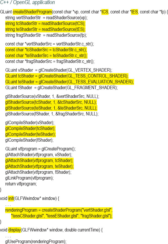
Program 12.1 shows the entire application code. Even a simple example such as this one is fairly complex, so many of the code elements will require explanation. Note that this is the first time we must build a GLSL rendering program with components beyond just vertex and fragment shaders. So, a four-parameter overloaded version of createShaderProgram() is implemented.
Program 12.1 Basic Tessellator Mesh
The resulting output mesh is shown in Figure 12.1.
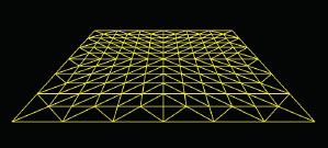
Figure 12.1
Tessellator triangle mesh output.
The tessellator produces a mesh of vertices defined by two parameters: inner level and outer level. In this case, the inner level is 12 and the outer level is 6—the outer edges of the grid are divided into 6 segments, while the lines spanning the interior are divided into 12 segments.
The specific relevant new constructs in Program 12.1 are highlighted. Let’s start by discussing the first portion—the C++/OpenGL code.
Compiling the two new shaders is done exactly the same as for the vertex and fragment shaders. They are then attached to the same rendering program, and the linking call is unchanged. The only new items are the constants for specifying the type of shader being instantiated—the new constants are as follows:
GL_TESS_CONTROL_SHADER
GL_TESS_EVALUATION_SHADER
Note the new items in the display() function. The glDrawArrays() call now specifies GL_PATCHES. When using tessellation, vertices sent from the C++/OpenGL application into the pipeline (i.e., in a VBO) aren’t rendered, but are usually control points, such as those we saw for Bézier curves. A set of control points is called a “patch,” and in those sections of the code using tessellation, GL_PATCHES is the only allowable primitive. The number of vertices in a patch is specified in the call to glPatchParameteri(). In this particular example, there aren’t any control points being sent, but we are still required to specify at least one. Similarly, in the glDrawArrays() call we indicate a start value of 0 and a vertex count of 1, even though we aren’t actually sending any vertices from the C++ program.
The call to glPolygonMode() specifies how the mesh should be rasterized. The default is GL_FILL. Shown in the code is GL_LINE, which, as we saw in Figure 12.1, caused only connecting lines to be rasterized (so we could see the grid itself that was produced by the tessellator). If we change that line of code to GL_FILL (or comment it out, resulting in the default behavior GL_FILL), we get the version shown in Figure 12.2.
Figure 12.2
Tessellated mesh rendered with GL_FILL.
Now let’s work our way through the four shaders. As indicated earlier, the vertex shader has little to do, since the C++/OpenGL application isn’t providing any vertices. All it contains is a uniform declaration, to match the other shaders, and an empty main(). In any case, it is a requirement that all shader programs include a vertex shader.
The Tessellation Control Shader specifies the topology of the triangle mesh that the tessellator is to produce. Six “level” parameters are set—two “inner” and four “outer” levels—by assigning values to the reserved words named gl_TessLevelxxx. This is for tessellating a large rectangular grid of triangles, called a quad.3 The levels tell the tessellator how to subdivide the grid when forming triangles, and they are arranged as shown in Figure 12.3.
Note the line in the control shader that says:
layout (vertices=1) out;
This is related to the prior GL_PATCHES discussion and specifies the number of vertices per “patch” being passed from the vertex shader to the control shader (and “out” to the evaluation shader). In this particular program there are none, but we still must specify at least one, because it also affects how many times the control shader executes. Later this value will reflect the number of control points and must match the value in the glPatchParameteri() call in the C++/OpenGL application.
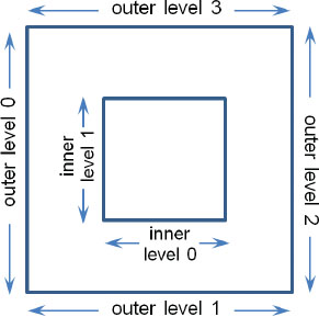
Figure 12.3
Tessellation levels.
Next let’s look at the Tessellation Evaluation Shader. It starts with a line of code that says:
layout (quads, equal_spacing, ccw) in;
This may at first appear to be related to the “out” layout statement in the control shader, but actually they are unrelated. Rather, this line is where we instruct the tessellator to generate vertices so they are arranged in a large rectangle (a “quad”). It also specifies the subdivisions (inner and outer) to be of equal length (later we will see a use for subdivisions of unequal length). The “ccw” parameter specifies the winding order in which the tessellated grid vertices are generated (in this case, counter-clockwise).
The vertices generated by the tessellator are then sent to the evaluation shader. Thus, the evaluation shader may receive vertices both from the control shader (typically as control points) and from the tessellator (the tessellated grid). In Program 12.1, vertices are only received from the tessellator.
The evaluation shader executes once for each vertex produced by the tessellator. The vertex location is accessible using the built-in variable gl_TessCoord. The tessellated grid is oriented such that it lies in the X-Z plane, and therefore gl_TessCoord’s X and Y components are applied at the grid’s X and Z coordinates. The grid coordinates, and thus the values of gl_TessCoord, range from 0.0 to 1.0 (this will be handy later when computing texture coordinates). The evaluation shader then uses the mvp matrix to orient each vertex (this was done in the vertex shader in examples from earlier chapters).
Finally, the fragment shader simply outputs a constant color yellow for each pixel. We can, of course, also use it to apply a texture or lighting to our scene as we saw in previous chapters.
12.2TESSELLATION FOR BÉZIER SURFACES
Let’s now extend our program so that it turns our simple rectangular grid into a Bézier surface. The tessellated grid should give us plenty of vertices for sampling the surface (and we can increase the inner/outer subdivision levels if we want more). What we now need is to send control points through the pipeline, and then use those control points to perform the computations to convert the tessellated grid into the desired Bézier surface.
Figure 12.4
Overview of tessellation for Bézier surfaces.
Assuming that we wish to build a cubic Bézier surface, we will need sixteen control points. We could send them from the C++ side in a VBO, or we could hardcode them in the vertex shader. Figure 12.4 shows an overview of the process with the control points coming from the C++ side.
Now is a good time to explain a bit more precisely how the tessellation control shader (TCS) works. Similar to the vertex shader, the TCS executes once per incoming vertex. Also, recall from Chapter 2 that OpenGL provides a built-in variable called gl_VertexID which holds a counter that indicates which invocation of the vertex shader is currently executing. A similar built-in variable called gl_InvocationID exists for the tessellation control shader.
A powerful feature of tessellation is that the TCS (and also the TES) shader has access to all of the control point vertices simultaneously, in arrays. At first, it may seem confusing that the TCS executes once per vertex, when each invocation has access to all of the vertices. It is also counterintuitive that the tessellation levels are specified in assignment statements which are redundantly set at each TCS invocation. Although all of this may seem odd, it is done this way because the tessellation architecture is designed so that TCS invocations can run in parallel.
OpenGL provides several built-in variables for use in the TCS and TES shaders. Ones that we have already mentioned are gl_InvocationID and of course gl_TessLevelInner and gl_TessLevelOuter. Here are some more details and descriptions of some of the most useful built-in variables:
Tessellation Control Shader (TCS) built-in variables:
•gl_in [ ] – an array containing each of the incoming control point vertices—one array element per incoming vertex. Particular vertex attributes can be accessed as fields using the “.” notation. One built-in attribute is gl_Position—thus, the position of incoming vertex “i” is accessed as gl_in[i].gl_Position.
•gl_out [ ] – an array for sending outgoing control point vertices to the TES—one array element per outgoing vertex. Particular vertex attributes can be accessed as fields using the “.” notation. One built-in attribute is gl_Position—thus, the position of outgoing vertex “i” is accessed as gl_out[i].gl_Position.
•gl_InvocationID – an integer ID counter indicating which invocation of the TCS is currently executing. One common use is for passing through vertex attributes; for example, passing the current invocation’s vertex position from the TCS to the TES would be done as follows: gl_out[gl_InvocationID].gl_Position = gl_in[gl_InvocationID].gl_Position;
Tessellation Evaluation Shader (TES) built-in variables:
•gl_in [ ] – an array containing each of the incoming control point vertices—one element per incoming vertex. Particular vertex attributes can be accessed as fields using the “.” notation. One built-in attribute is gl_Position—thus, incoming vertex positions are accessed as gl_in[xxx].gl_Position.
•gl_Position – output position of a tessellated grid vertex, possibly modified in the TES. It is important to note that gl_Position and gl_in[xxx].gl_Position are different—gl_Position is the position of an output vertex that originated in the tessellator, while gl_in[xxx].gl_Position is a control point vertex position coming into the TES from the TCS.
It is important to note that input and output control point vertex attributes in the TCS are arrays. By contrast, input control point vertices and vertex attributes in the TES are arrays, but output vertices are scalars. Also, it is easy to become confused as to which vertices are for control points and which are tessellated and then moved to form the resulting surface. To summarize, all vertex inputs and outputs to the TCS are control points, whereas in the TES, gl_in[ ] holds incoming control points, gl_TessCoord holds incoming tessellated grid points, and gl_Position holds output surface vertices for rendering.
Our tessellation control shader now has two tasks: specifying the tessellation levels and passing the control points through from the vertex shader to the evaluation shader. The evaluation shader can then modify the locations of the grid points (the gl_TessCoords) based on the Bézier control points.
Program 12.2 shows all four shaders—vertex, TCS, TES, and fragment—for specifying a control point patch, generating a flat tessellated grid of vertices, repositioning those vertices on the curved surface specified by the control points, and painting the resulting surface with a texture image. It also shows the relevant portion of the C++/OpenGL application, specifically in the display() function. In this example, the control points originate in the vertex shader (they are hardcoded there) rather than entering the OpenGL pipeline from the C++/OpenGL application. Additional details follow after the code listing.
Program 12.2 Tessellation for Bézier Surface
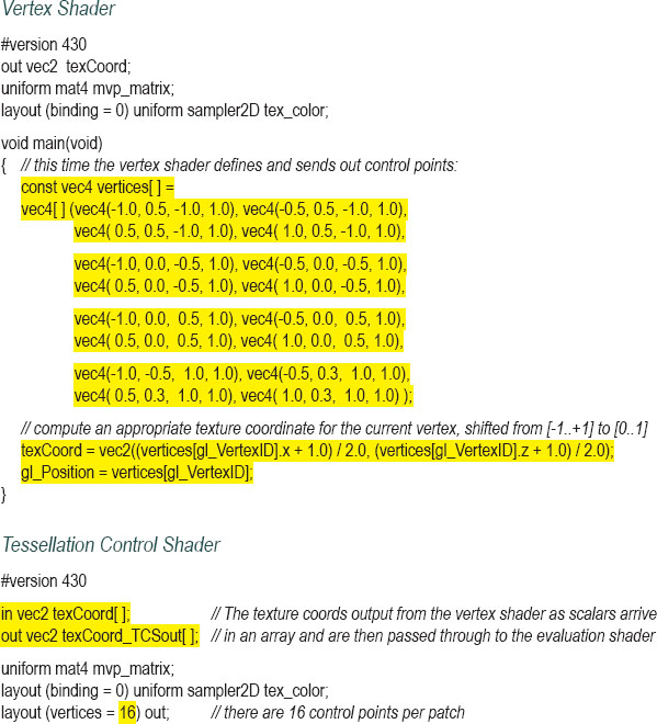
The vertex shader now specifies sixteen control points (the “patch” vertices) representing a particular Bézier surface. In this example they are all normalized to the range [-1..+1]. The vertex shader also uses the control points to determine texture coordinates appropriate for the tessellated grid, with values in the range [0..1]. It is important to reiterate that the vertices output from the vertex shader are not vertices that will be rasterized, but instead are Bézier control points. When using tessellation, patch vertices are never rasterized—only tessellated vertices proceed to rasterization.
The control shader still specifies the inner and outer tessellation levels. It now has the additional responsibility of forwarding the control points and texture coordinates to the evaluation shader. Note that the tessellation levels only need to be specified once, and therefore that step is done only during the 0th invocation (recall that the TCS runs once per vertex—thus there are sixteen invocations in this example). For convenience, we have specified thirty-two subdivisions for each tessellation level.
Next, the evaluation shader performs all of the Bézier surface computations. The large block of assignment statements at the beginning of main() extract the control points from the incoming gl_Position’s of each incoming gl_in (note that these correspond to the control shader’s gl_out variable). The weights for the blending functions are then computed using the grid points coming in from the tessellator, resulting in a new outputPosition to which the model-view-projection matrix is then applied, producing an output gl_Position for each grid point and forming the Bézier surface.
It is also necessary to create texture coordinates. The vertex shader only provided one for each control point location. But it isn’t the control points that are being rendered—we ultimately need texture coordinates for the much larger number of tessellated grid points. There are various ways of doing this—here we linearly interpolate them using GLSL’s handy mix function. The mix() function expects three parameters: (a) starting point, (b) ending point, and (c) interpolation value, which ranges from 0 to 1. It returns the value between the starting and ending point corresponding to the interpolation value. Since the tessellated grid coordinates also range from 0 to 1, they can be used directly for this purpose.
This time in the fragment shader, rather than outputting a single color, standard texturing is applied. The texture coordinates in the attribute texCoord_TESout are those that were produced in the evaluation shader. The changes to the C++ program are similarly straightforward—note that a patch size of 16 is now specified. The resulting output is shown in Figure 12.5 (a tile texture from [LU16] is applied).
Figure 12.5
Tessellated Bézier surface.
12.3TESSELLATION FOR TERRAIN / HEIGHT MAPS
Recall that performing height mapping in the vertex shader can suffer from an insufficient number of vertices to render the desired detail. Now that we have a way to generate lots of vertices, let’s go back to Hastings-Trew’s moon surface texture map (from [HT16]) and use it as a height map by raising tessellated vertices to produce moon surface detail. As we will see, this has the advantages of achieving vertex geometry that better matches the moon image, along with improved silhouette (edge) detail.
Our strategy is to modify Program 12.1, placing a tessellated grid in the X-Z plane, and use height mapping to set the Y coordinate of each tessellated grid point. To do this a patch isn’t needed, because we can hardcode the location of the tessellated grid, so we will specify the required minimum of 1 vertex per patch in glDrawArrays() and glPatchParameteri(), as was done in Program 12.1. Hastings-Trew’s moon texture image is used both for color and as the height map.
We generate vertex and texture coordinates in the evaluation shader by mapping the tessellated grid’s gl_TessCoord values to appropriate ranges for vertices and textures.4 The evaluation shader also is where the height mapping is performed, by adding a fraction of the color component of the moon texture to the Y component of the output vertex. The changes to the shaders are shown in Program 12.3.
Program 12.3 Simple Tessellated Terrain
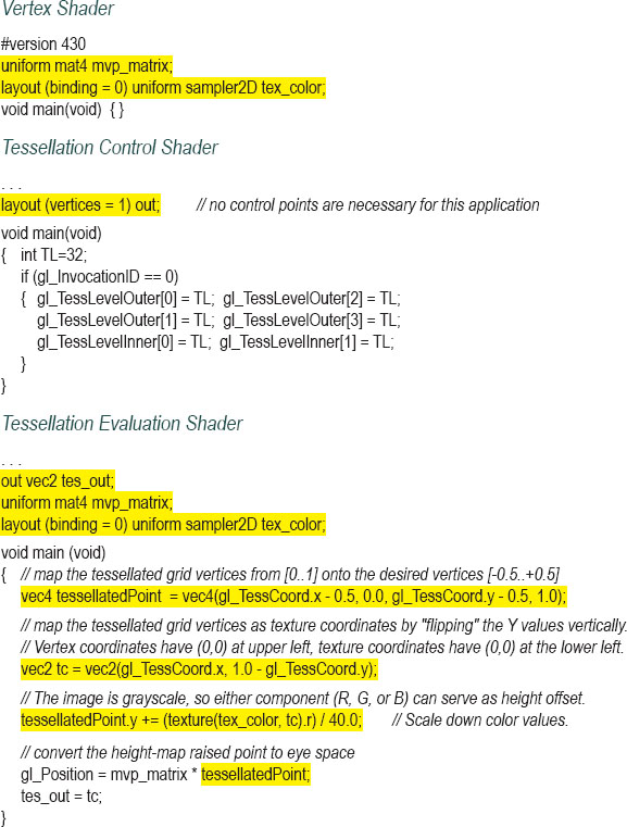
The fragment shader is similar to the one for Program 12.2, and simply outputs the color based on the texture image. The C++/OpenGL application is essentially unchanged—it loads the texture (serving as both the texture and height map) and enables a sampler for it. Figure 12.6 shows the texture image (on the left) and the final output of this first attempt, which unfortunately does not yet achieve proper height mapping.
The first results are severely flawed. Although we can now see silhouette detail on the far horizon, the bumps there don’t correspond to the actual detail in the texture map. Recall that in a height map, white is supposed to mean “high,” and black is supposed to mean “low.” The area at the upper right, in particular, shows large hills that bear no relation to the light and dark colors in the image.
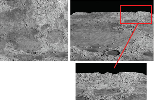
Figure 12.6
Tessellated terrain – failed first attempt, with insufficent number of vertices.
The cause of this problem is the resolution of the tessellated grid. The maximum number of vertices that can be generated by the tessellator is hardware dependent, and a maximum value of at least 64 for each tessellation level is all that is required for compliance with the OpenGL standard. Our program specified a single tessellated grid with inner and outer tessellation levels of 32, so we generated about 32*32, or just over 1000 vertices, which is insufficient to reflect the detail in the image accurately. This is especially apparent along the upper right (enlarged in the figure)—the edge detail is only sampled at 32 points along the horizon, producing large, random-looking hills. Even if we increased the tessellation values to 64, the total of 64*64 or just over 4000 vertices would still be woefully inadequate to do height-mapping using the moon image.
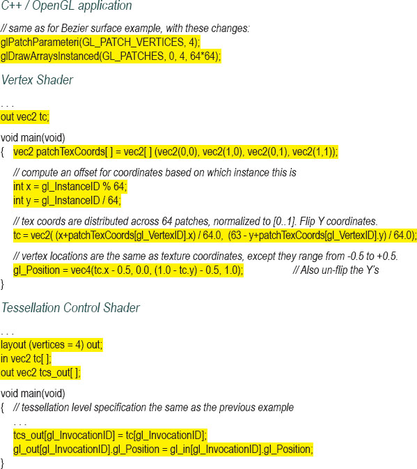
A good way to increase the number of vertices is by using instancing, which we saw in Chapter 4. Our strategy will be to have the tessellator generate grids and use instancing to repeat this many times. In the vertex shader we build a patch defined by four vertices, one for each corner of a tessellated grid. In our C++/OpenGL application we change the glDrawArrays() call to glDrawArraysInstanced(). There, we specify a grid of 64 by 64 patches, each of which contains a tessellated mesh with levels of size 32. This will give us a total of 64*64*32*32, or over four million vertices.
The vertex shader starts by specifying four texture coordinates (0,0), (0,1), (1,0), and (1,1). When using instancing, recall that the vertex shader has access to an integer variable gl_InstanceID, which holds a counter corresponding to the glDrawArraysInstanced() call that is currently being processed. We use this ID value to distribute the locations of the individual patches within the larger grid. The patches are positioned in rows and columns, the first patch at location (0,0), the second at (1,0), the next at (2,0), and so on, and the final patch in the first column at (63,0). The next column has patches at (0,1), (1,1), and so forth up to (63,1). The final column has patches at (0,63), (1,63), and so on up to (63,63). The X coordinate for a given patch is the instance ID modulo 64, and the Y coordinate is the instance ID divided by 64 (with integer division). The shader then scales the coordinates back down to the range [0..1].
The control shader is unchanged, except that it passes through the vertices and texture coordinates.
Next, the evaluation shader takes the incoming tessellated grid vertices (specified by gl_TessCoord) and moves them into the coordinate range specified by the incoming patch. It does the same for the texture coordinates. It also applies height mapping in the same way as was done in Program 12.3. The fragment shader is unchanged.
The changes to each of the components are shown in Program 12.4. The result is shown in Figure 12.7. Note that the highs and lows now correspond much more closely to light and dark sections of the image.
Program 12.4 Instanced Tessellated Terrain
Now that we have achieved height mapping, we can work on improving it and incorporating lighting. One challenge is that our vertices do not yet have normal vectors associated with them. Another challenge is that simply using the texture image as a height map has produced an overly “jagged” result—in this case because not all grayscale variation in the texture image is due to height. For this particular texture map, it so happens that Hastings-Trew has already produced an improved height map that we can use [HT16]. It is shown in Figure 12.8 (on the left).
To create normals, we could compute them on the fly by generating the heights of neighboring vertices (or neighboring texels in the height map), building vectors connecting them, and using a cross product to find the normal. This requires some tuning, depending on the precision of the scene (and/or the height map image). Here we have instead used the GIMP “normalmap” plugin [GP16] to generate a normal map based on Hastings-Trew’s height map, shown in Figure 12.8 (on the right).
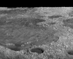
Figure 12.7
Tessellated terrain – second attempt, with instancing.
Figure 12.8
Moon surface: height map [HT16] and normal map.
Most of the changes to our code are now simply to implement the standard methods for Phong shading:
•C++/OpenGL application
We load and activate an additional texture to hold the normal map. We also add code to specify the lighting and materials as we have done in previous applications.
•Vertex shader
The only additions are declarations for lighting uniforms and the sampler for the normal map. Lighting code customarily done in the vertex shader is moved to the tessellation evaluation shader, because the vertices aren’t generated until the tessellation stage.
•Tessellation Control shader
The only additions are declarations for lighting uniforms and the sampler for the normal map.
•Tessellation Evaluation shader
The preparatory code for Phong lighting is now placed in the evaluation shader:
varyingVertPos = (mv_matrix * position).xyz;
varyingLightDir = light.position - varyingVertPos;
•Fragment shader
The typical code sections, described previously, for computing Phong (or Blinn-Phong) lighting are done here, as well as the code to extract normals from the normal map. The lighting result is then combined with the texture image with a weighted sum.
Figure 12.9
Tessellated terrain with normal map and lighting (light source positioned at left and at right respectively).
The final result, with height and normal mapping and Phong lighting, is shown in Figure 12.9. The terrain now responds to lighting. In this example, a positional light has been placed to the left of center in the image on the left, and to the right of center in the image on the right.
Although the response to the movement of the light is difficult to tell from a still picture, the reader should be able to discern the diffuse lighting changes and that specular highlights on the peaks are very different in the two images. This is of course more obvious when the camera or the light source is moving. The results are still imperfect, because the original texture that is incorporated in the output includes shadows that will appear on the rendered result, regardless of lighting.
12.4CONTROLLING LEVEL OF DETAIL (LOD)
Using instancing to generate millions of vertices in real time, as in Program 12.4, is likely to place a load on even a well-equipped modern computer. Fortunately, the strategy of dividing the terrain into separate patches, as we have done to increase the number of generated grid vertices, also affords us a nice mechanism for reducing that load.
Of the millions of vertices being generated, many aren’t necessary. Vertices in patches that are close to the camera are important because we expect to discern detail in nearby objects. However, the further the patches are from the camera, the less likely there will even be enough pixels in the rasterization to warrant the number of vertices we are generating!
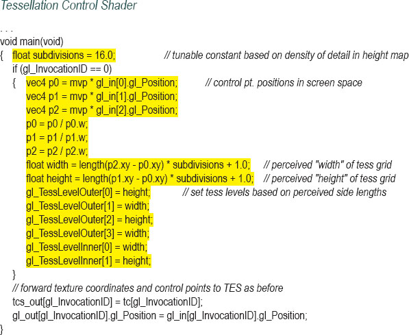
Changing the number of vertices in a patch based on the distance from the camera is a technique called level of detail, or LOD. Sellers et al. describe a way of controlling LOD in instanced tessellation [SW15], by modifying the control shader. Program 12.5 shows a simplified version of the approach by Sellers et al. The strategy is to use the patch’s perceived size to determine the values of its tessellation levels. Since the tessellated grid for a patch will eventually be placed within the square defined by the four control points entering the control shader, we can use the locations of the control points relative to the camera to determine how many vertices should be generated for the patch. The steps are as follows:
1.Calculate the screen locations of the four control points by applying the MVP matrix to them.
2.Calculate the lengths of the sides of the square (i.e., the width and height) defined by the control points (in screen space). Note that even though the four control points form a square, these side lengths can differ because the perspective matrix has been applied.
3.Scale the lengths’ values by a tunable constant, depending on the precision needed for the tessellation levels (based on the amount of detail in the height map).
4.Add 1 to the scaled length values, to avoid the possibility of specifying a tessellation level of 0 (which would result in no vertices being generated).
5.Set the tessellation levels to the corresponding calculated width and height values.
Recall that in our instanced example we are not creating just one grid, but 64*64 of them. So the five steps in the previous list are performed for each patch. Thus, the level of detail varies from patch to patch.
All of the changes are in the control shader and are shown in Program 12.5, with the generated output following in Figure 12.10. Note that the variable gl_InvocationID refers to which vertex in the patch is being processed (not which patch is being processed). Therefore, the LOD computation which tells the tessellator how many vertices to generate occurs during the processing of the 0th vertex in each patch.
Program 12.5 Tessellation Level of Detail (LOD)
Applying these control shader changes to the instanced (but not lighted) version of our scene from Figure 12.7, and replacing the height map with Hastings-Trew’s more finely tuned version shown in Figure 12.8 produces the improved scene, with more realistic horizon detail, shown in Figure 12.10.
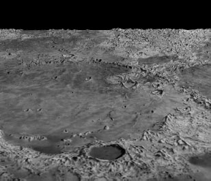
Figure 12.10
Tessellated moon with controlled level of detail (LOD).
In this example it is also useful to change the layout specifier in the evaluation shader from:
layout (quads, equal_spacing) in;
layout (quads, fractional_even_spacing) in;
The reason for this modification is difficult to illustrate in still images. In an animated scene, as a tessellated object moves through 3D space, if LOD is used it is sometimes possible to see the changes in tessellation levels on the surface of the object as wiggling artifacts called “popping.” Changing from equal spacing to fractional spacing reduces this effect by making the grid geometry of adjacent patch instances more similar, even if they differ in level of detail. (See Exercises 12.2 and 12.3.)
Employing LOD can dramatically reduce the load on the system. For example, when animated, the scene might be less likely to appear jerky or to lag than could be the case without controlling LOD.
Applying this simple LOD technique to the version that includes Phong shading (i.e., Program 12.4) is a bit trickier. This is because the changes in LOD between adjacent patch instances can in turn cause sudden changes to the associated normal vectors, causing popping artifacts in the lighting! As always, there are tradeoffs and compromises to consider when constructing a complex 3D scene.
SUPPLEMENTAL NOTES
Combining tessellation with LOD is particularly useful in real-time virtual reality applications that require both complex detail for realism and frequent object movement and/or changes in camera position, such as in computer games. In this chapter we have illustrated the use of tessellation and LOD for real-time terrain generation, although it can also be applied in other areas such as in displacement mapping for 3D models (where tessellated vertices are added to the surface of a model and then moved so as to add detail). It is also useful in computer-aided-design applications.
Sellers et al. extends the LOD technique (shown in Program 12.5) further than we have presented, by also eliminating vertices in patches that are behind the camera (they do this by setting their inner and outer levels to zero) [SW15]. This is an example of a culling technique, and it is a very useful one because of the load that instanced tessellation can still place on the system.
The four-parameter version of createShaderProgram() described in Program 12.1 is added to the Utils.cpp file. Later, we will add additional versions to accommodate the geometry shader stage.
12.1Modify Program 12.1 to experiment with various values for inner and outer tessellation levels, and observe the resulting rendered mesh.
12.2Modify Program 12.1 by changing the layout specifier in the evaluation shader from equal_spacing to fractional_even_spacing, as shown in Section 12.4. Observe the effect on the generated mesh.
12.3Test Program 12.5 with the layout specifier in the evaluation shader set to equal_spacing, and then to fractional_even_spacing, as described in Section 12.4. Observe the effects on the rendered surface as the camera moves. You should be able to observe popping artifacts in the first case, which are mostly alleviated in the second case.
12.4(PROJECT) Modify Program 12.3 to utilize a height map of your own design (you could use the one you built previously in Exercise 10.2). Then add lighting and shadow-mapping so that your tessellated terrain casts shadows. This is a complex exercise, because some of the code in the first and second shadow-mapping passes will need to be moved to the evaluation shader.
References
[GP16] |
GIMP Plugin Registry, normalmap plugin, accessed October 2018, https://code.google.com/archive/p/gimp-normalmap |
[HT16] |
J. Hastings-Trew, JHT’s Planetary Pixel Emporium, accessed October 2018, http://planetpixelemporium.com/ |
[LU16] |
F. Luna, Introduction to 3D Game Programming with DirectX 12, 2nd ed. (Mercury Learning, 2016). |
[SW15] |
G. Sellers, R. Wright Jr., and N. Haemel, OpenGL SuperBible: Comprehensive Tutorial and Reference, 7th ed. (Addison-Wesley, 2015). |
[TS16] |
Tessellation, Wikipedia, accessed October 2018, https://en.wikipedia.org/wiki/Tessellation |
1Although the GLU toolset previously included a utility for tessellation much earlier called gluTess. In 2001, Radeon released the first commercial graphics card with tessellation support, but there were few tools able to take advantage of it.
2Or lines, but we will focus on triangles.
3The tessellator is also capable of building a triangular grid of triangles, but that isn’t covered in this textbook.
4In some applications the texture coordinates are produced externally, such as when tessellation is being used to provide additional vertices for an imported model. In such cases, the provided texture coordinates would need to be interpolated.