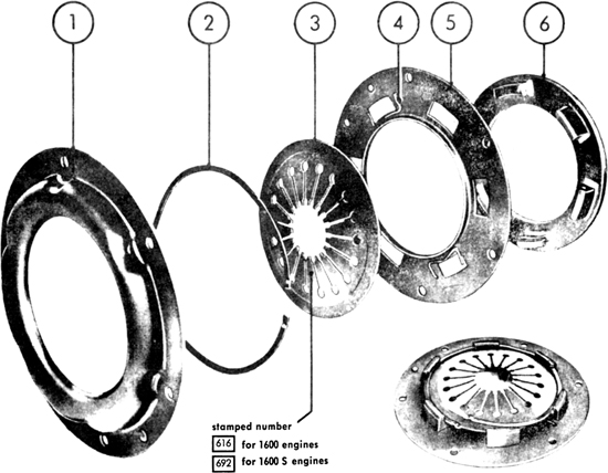
FIG 5:1 Clutch cover and pressure plate components. View (bottom right) shows diaphragm spring lock ring partially removed
5:4 Removing and dismantling clutch
5:5 Reassembling and installing clutch
5:6 Variations on later 1600S.90 clutch
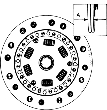
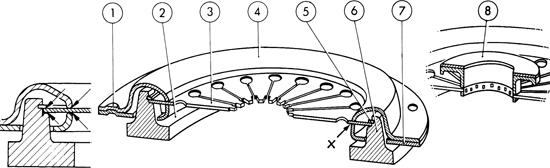
A single dry plate clutch with diaphragm spring is fitted to all models under review. The pressure plate and spring components can be seen in FIG 5:1 while the driven plate with its friction linings is shown in FIG 5:2. The location of the pressure plate components is shown in section in FIG 5:3. Note how earlier versions had a release plate 8 secured to the fingers of the diaphragm spring.
The clutch cover 4 is bolted to the flywheel and the linings of the driven plate are tightly nipped between the face of pressure plate 6 and the flywheel face by pressure from spring 3. As the driven plate is splined to the gearbox mainshaft, the engine can be directly connected to the transmission if a gear is selected. To release the clutch when the pedal is depressed, a cable operates a shaft and release bearing (see FIG 5:11). The release bearing presses on the tips of the fingers of the diaphragm spring. As the spring is convex, this action flattens it and causes the outer edge to move outwards, pressing on lock ring 5 and lifting pressure plate 6 away from the driven plate. The spring actually pivots at point X. The released driven plate is no longer nipped and ceases to transmit drive from the engine.
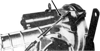
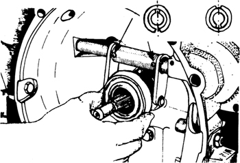
At the transmission end the clutch cable should be kept lightly greased and the clevis pin on the lever given a few spots of engine oil (see FIG 5:4).
The only other maintenance is clutch pedal adjustment. The makers emphasise the great importance of correct adjustment to ensure that the clutch neither slips nor drags. A clutch which does not fully disengage will throw extra work on the synchromesh devices in the gearbox and cause them to wear rapidly. A slipping clutch will overheat and glaze the linings.
The clutch cable may be adjusted at either the pedal, or the lever on the transmission casing (see FIG 5:4). To adjust at the pedal, remove mat and floor board from behind pedal. Unlock and turn adjusting nut until the pedal pad has free movement of 20 to 25 mm (¾ to 1 inch) before starting to operate. It may be necessary to hold the cable bolt with pliers when adjusting.
To adjust at the lever, jack up car and remove lefthand rear wheel. Refer to FIG 5:4 and loosen locknut for clevis. Remove spring clip and clevis pin. Turn the clevis on the cable bolt to shorten or lengthen the cable as required. Make sure that the clevis is not screwed on so far that the cable bolt fouls the lever. Fit the clevis pin from the outside, with the spring clip on top. Operate the clutch pedal several times and check the free travel. When satisfied, tighten the clevis locknut and grease the cable and threads.
FIG 5:1 Clutch cover and pressure plate components. View (bottom right) shows diaphragm spring lock ring partially removed
Keyt o Fig 5:1
1 Cover
2 Lock ring
3 Diaphragm spring
4 Spring tensioner
5 Counter plate
6 Pressure plate
Adjusting pedal stop:
Refer to FIG 5:5. Run car until gearbox is warm. Depress pedal to stop. In this position reverse gear should just engage silently. Make sure cable is correctly adjusted as described in preceding notes. When correct, adjust the position of the pedal stop. This is a slotted plate.
To adjust, remove floor mat and loosen stop screws. Move plate to required position and tighten screws. Check that reverse gear will just engage silently with pedal depressed.
Removing:
Remove floor board behind pedal. Remove locknut and adjusting nut from cable. Jack up car and remove lefthand rear wheel. At rear end of cable, loosen clevis locknut and remove clevis clip and pin. Remove clevis and locknut. Release cable casing from bracket on gearbox. Pull cable rearwards out of casing and conduit.
FIG 5:2 Clutch driven plate showing friction linings and six shock absorbing springs round hub. I thickness is measured at A
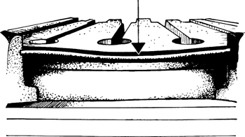
FIG 5:3 Section through diaphragm spring and pressure plate assembly. Lubrication points are on left, early release plate fitted to spring fingers on right. Later models are as central view
Key to Fig 5:3
1 Indexing dent
2 Pressure plate
3 Diaphragm spring
4 Clutch cover
5 Lock ring
6 Pressure plate
7 Counter plate
8 Release plate
Installing:
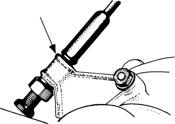
Grease cable and slide it through casing several times. Pump grease into the rear end of the cable conduit until a second operator can see clean grease emerging from the front end. Fit the cable from the rear, the observer keeping the end of the conduit closed to prevent the grease from being pushed out. Connect front end of cable to pedal link. At rear end fit casing adjusting bolt and locknut into gearbox bracket. Refer to FIG 5:6 and note that the bevel on the locknut fits into the bracket. Cable casing should bow about ¾ inch between body and bracket. Make sure that at least three threads protrude at the point indicated by the arrow, so that the rubber dust cover can be fitted. Grease the clevis and fit to the lever. Adjust clutch travel as described in Section 5:2. Adjust pedal stop if needed.
Remove the engine (see Chapter 1). Refer to FIG 5:1 and release coverplate 1 from flywheel (6 bolts). Slacken these evenly and diagonally to avoid lop-sided stressing of the cover and spring. Lift away pressure plate assembly and driven plate.
To dismantle, start at one end and remove lockring 2 (see also part 5 in FIG 5:3). Remove the diaphragm spring. Counter plate 5 and pressure plate 6 are balanced as a unit, so mark their relative positions before parting them. Press them apart, noting tensioner spring 4. Clean all parts with solvent.
Inspect the pressure plate for wear, distortion, scoring or break-up of the surface. Do not grip the plate in a vice by the spring lugs. Hold it by theouter rim. Check the spring for distortion or cracks. Renew parts as required.
Check the driven plate linings for cracks and damage through overheating or oil. The thickness as measured at A in FIG 5:2 must be not less than 7.5 mm or .296 inch. see Section 5:6 for variations on later 1600S.90. It is not advisable to rivet new linings into place and renewal is best. If thickness is acceptable, check fit of splines in hub and those on gearbox mainshaft. Plate should slide freely without undue slackness. Check that the six shock-absorbing springs round the hub are neither slack nor broken.
Apply a thin smear of graphite grease to the sides of the spring lugs of the pressure plate and insert into the coverplate, aligning the marks to ensure correct balance. Insert the hooks of the spring tensioners into the counter plate. Raise counter plate slightly and press springs over lugs on pressure plate. Put a thin film of graphite grease on the bearing surfaces in the lugs and fit the diaphragm spring. Fit lock ring into grooves in lugs. The flat parts lie in the grooves and the arched sections must bear down on the diaphragm spring as shown in FIG 5:7. Make sure the lock ring is fully seated in the grooves. Fit the cover so that the indexing dent fits over the corresponding dent in the counter plate (see 1 in FIG 5:3).
FIG 5:4 Rear end of clutch cable showing clevis attached to lever. Arrow points to adjustment thread and locknut
FIG 5:5 Adjustment of pedal free play is made by altering position of slotted stop plate shown fully extended in dotted position
FIG 5:6 Arrow points to bracket on gearbox which carries clutch cable housing end. Three threads must protrude on the right to take the rubber dust cover
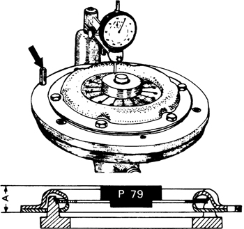
FIG 5:8 Adjusting clutch by means of gauging fixture VW.254. Peg 26 mm high is arrowed. Lower view shows that face of gauging ring P.79 is height A from flywheel face. Correct figure is 25.5 to 26 mm (1.005 to 1.024 inch)
The position of the release plate (see right in FIG 5:3) is important and the method of adjusting the position will be described. It is not possible to use the same method for the later type of clutch which has no release plate, unless the official tool VW.254 is available. Normally the best plan is to entrust the work to an accredited agent. However, the method may be of interest.
It will be seen from FIG 5:3 that the diaphragm spring pivots on the ridges of the cover and the counter plate at point X. Any adjustment of this point nearer to or farther from the flywheel will affect the position of the diaphragm release plate or the fingers. A change of .1 mm (.004 inch) at X will alter the position of the release plate or the fingers by .40 mm (.016 inch). The gauging and adjustment is carried out as follows:
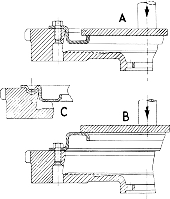
The clutch assembly is mounted on the base plate of the tool with a plate in position which simulates the clutch driven plate when compressed. It is 8.6 mm (.340 inch) thick. The spring is compressed and the coverplate bolted down evenly. The central gauging ring P.79 is used when the clutch has no release plate. This is shown in FIG 5:8, and its top face is the same distance from the base as if a release plate were fitted. The dial gauge is zeroed on the peg to the left which is arrowed. This is 26 mm high. The gauge is then swung across and the height of the release plate or the gauging ring is checked. It should be 26 to 25.50 mm from the base (or 1.024 to 1.005 inch). If adjustment is needed, a little thought will indicate in which direction the cover and counter plates must be bent. The method is shown in FIG 5:9. The plates are mounted separately in a flywheel which has a hole in it to accommodate the indexing dent as shown at C in the illustration. If the measurement is too small, a press and thick circular plate are used as in A to press down on the cover. If too large, the cover is placed as in B. Remember that any deflection at the pivot point will be multiplied four times at the release plate or fingers. A corresponding adjustment must then be made to the counter plate.
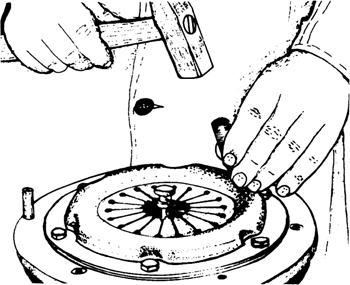
When assembled, the gap between the two plates must be such that the diaphragm spring will be pre-loaded by approximately .30 mm (.013 inch). The assembled clutch must be operated several times and the runout of the gauging ring or the release bearing face checked with the dial gauge. Deflection should not exceed 1.2 mm (.047 inch). Normally the wobble should be .80 mm (.030 inch) or less. Excessive runout can be rectified as shown in FIG 5:10. A brass drift is used to take hammer blows on the cover, which must be bent inwards adjacent to the highest point of runout.
Installing clutch:
Before refitting the clutch, check the flywheel face for wear and runout. The flywheel face can be reground providing not more than .20 mm (.008 inch) is removed. Polish with superfine emerycloth. At the same time it would be a good plan to check the pilot bearing in the gland nut which secures the flywheel. This supports the rear end of the gearbox mainshaft. Insert about 2cc of special graphite grease in the bearing. Check the release bearing (see Section 5:7) and the bearings for the cross-shaft.
FIG 5:9 Setting coverplate under press to obtain correct gauging as shown in FIG 5:8. Measurement too small, use method A. Measurement too large, use method B. Hole to accommodate indexing dent shown at C
The hub of the clutch driven plate must line up with the pilot bearing or it will be impossible to fit the engine to the transmission. Alignment is assured by using an old gearbox mainshaft or a mandrel. For one-off purposes this could be turned from a length of hardwood dowelling the small diameter fitting the flywheel pilot bearing and the larger being a neat fit in the hub.
With the driven plate centrally placed, fit the coverplate assembly. Tighten the six bolts a turn at a time, working diagonally to avoid any distortion of the spring or cover. Remove the driven plate mandrel.
Starting at engine No. 804001 the 1600S.90 engine was fitted with an A.12 Haeussermann clutch instead of the A.10 originally fitted. Differences are as follows.
1 Lining diameter increased from 180 to 200 mm (7 to 7⅞ inch).
2 Driven plate thickness increased from 9.10 to 9.50 mm (.358 to .374 inch) to 9.7 to 10.1 mm (.382 to .398 inch) uncompressed.
3 Code number for spring changed from 692 to 692/3A.
4 Spring diameter increased from 150 mm to 165 mm (5.9 to 6.5 inch).
5 Clutch recess in flywheel increased to 205 mm (8inch) diameter.
6 Clutch recess in flywheel increased to 25 mm (.98 inch) in depth.
With the engine removed, the clutch release bearing can be seen in the transmission housing as shown in FIG 5:11. Remove return spring from outside lever then release the bearing from its guide sleeve. Check the bearing for wear and roughness in action and renew if necessary.
If the cross-shaft bearings are worn, remove the shaft by driving out the roll-pins which secure the fork. Worn bushes can be driven out and new ones drifted into place. Official tools are P.62 and P.64.
When refitting the cross-shaft and securing the fork, note that there are two roll-pins at each station, one being inserted in the other. Fit the pins in such a way that the slots are opposite each other and disposed vertically (see inset in FIG 5:11). Apply a thin film of graphite grease to the fork and install the bearing. Set the face of the bearing quite square with the joint face of the transmission housing and measure the distance between the faces. The bearing should be inset 50 mm (1 inch) from the housing face. Adjust at the cable clevis on the outside lever but do not screw the cable thread in so far that it fouls the lever.
When the engine is installed, check the clutch pedal travel and adjust if necessary (see Section 5:2).
FIG 5:11 Clutch release fork secured by two sets of two roll-pins, one inside the other. Inset shows correct positioning of slots in pins. They must be vertical and opposite
(a) Noisy clutch
1 Worn bush in flywheel gland nut
2 Worn clutch release bearing
3 Broken or loose springs in driven plate
(b) Chatter or grabbing
1 Transmission mountings loose or defective
2 Worn pressure plate
3 Diaphragm spring distorted
4 Cable housing slack
5 Distorted or flattened cushioning segments between driven plate linings
6 Grease or oil on friction linings
(c) Dragging or failure to release
1 Check 5 and 6 in (b)
2 Too much free play in pedal
3 Driven plate or main drive shaft not running true
4 Bush in flywheel gland nut tight or unlubricated
5 Stiffness in pedal, cable or release mechanism, not enough free travel
6 Broken friction linings
(d) Slipping clutch
1 Check 6 in (b) and 5 in (c)
2 Weak diaphragm spring
3 Worn friction linings