2
Characteristics of UD Ply
2.1. State of stress of UD ply
A UD ply (common abbreviation for unidirectional, which we will use throughout this book) is composed of fibers, all facing the same way, and resin. We call l the longitudinal direction, t the transverse direction and z the out-of-plane direction.
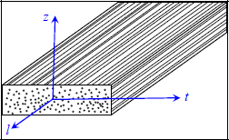
Figure 2.1. Defining the coordinate system of a UD ply. For a color version of this figure, see www.iste.co.uk/bouvet/aeronautical2.zip
REMARK.– In this book the matrices will be double underlined and vectors will have a single line under them, but only where confusion is possible (which will rarely be the case) in order to alleviate notations.
Obviously, the behavior of such a material is not isotropic but rather orthotropic: it presents three planes of symmetry (l, t), (t, z) and (l, z), and (l, t, z) which define the orthotropic coordinate system. As a reminder, an isotropic material is one that presents the same behavior in all directions in space and a material that presents no symmetry is considered anisotropic.
In practice, a UD ply being thin (a few tenths of a millimeter in thickness), we can suppose that stress is planar:
And the stress matrix is:
We will begin by studying its behavior in a plane.
2.2. Tensile test in the l-direction
If we perform a tensile test along the direction of fibers l, we typically observe an elongation along the l-direction, shrinking along the t-direction and no shearing, meaning that the specimen maintains its initial rectangular shape. The stress and strain during the test are therefore:
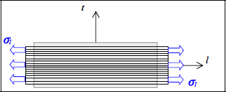
Figure 2.2. Tensile test of a UD ply along the longitudinal direction. For a color version of this figure, see www.iste.co.uk/bouvet/aeronautical2.zip
Furthermore, we observe that the strain is globally linear depending on the stress (keeping in mind that these behavior laws mainly serve as theoretical models and that when we take a closer look, reality is always more complicated):
With El being Young’s modulus (in either MPa or GPa) in the l-direction and νlt Poisson’s ratio (no unit) along the l-direction.
If we continue to increase the load, we observe a sudden rupture with a practically linear behavior all the way through to the end.
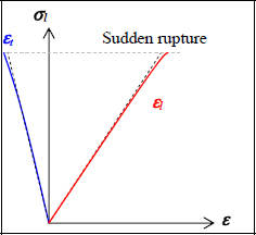
Figure 2.3. Stress / strain curves of a tensile test of a UD ply in the longitudinal direction. For a color version of this figure, see www.iste.co.uk/bouvet/aeronautical2.zip
2.3. Tensile test along the t-direction
If we now perform a tensile test in transversal direction t, we similarly observe an elongation proportional to σt along the t-direction, a shrinking proportional to σt along the l-direction, and no shearing.
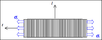
Figure 2.4. Tensile test of a UD ply in the transverse direction. For a color version of this figure, see www.iste.co.uk/bouvet/aeronautical2.zip
With:
With Et being Young’s modulus in the t-direction and νtl Poisson’s ratio along the t-direction. El and Et are generally different and so are νlt and νtl. We can also demonstrate, thanks to energetic considerations, that if the relations (equations [2.4] and [2.6]) are linear, then we necessarily get:
And if we continue to increase the load, we observe a sudden rupture with a practically linear behavior all the way through to the end.
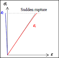
Figure 2.5. Stress / strain curves of a tensile test of a UD ply in the transverse direction. For a color version of this figure, see www.iste.co.uk/bouvet/aeronautical2.zip
2.4. Shear test
Performing a pure shear test, we get a shear strain γlt proportional to τlt, and elongations εl and εt are null:
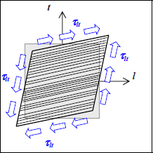
Figure 2.6. In-plane shear test. For a color version of this figure, see www.iste.co.uk/bouvet/aeronautical2.zip
With:
With Glt as the shear modulus (in MPa or GPa). We note in passing that performing a shear test is far more complicated than performing a tensile test: for example, we need to perform a torsion test of a thin tube. In practice, we can also find shear characteristics using an off-axis tensile test (see Chapter 3).
Continuing to increase the load, we observe nonlinear behavior with an irreversible strain and a sudden rupture.
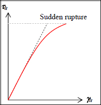
Figure 2.7. Stress / strain curve of an in-plane shear test of a UD ply. For a color version of this figure, see www.iste.co.uk/bouvet/aeronautical2.zip
2.5. General case
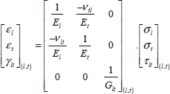
If we now add these three elementary stresses, we then obtain:
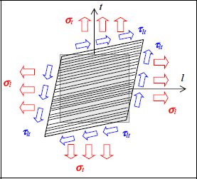
Figure 2.8. General case: tension along l-direction, along t-direction and in-plane shear. For a color version of this figure, see www.iste.co.uk/bouvet/aeronautical2.zip
That can be put in the following form:
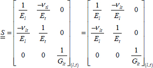
However, this relation is only true in the orthotropic coordinate system. This 3×3 matrix is called a compliance matrix; the matrix is called S and is symmetrical:
With:
We can reverse this compliance matrix to obtain stiffness matrix  :
:
For example, T300/914 – which is a composite formed of approximately 50% in volume of 7 μm-diameter carbon fibers and 50% in volume of epoxy resin and is presented under the form of 0.125 mm-thick pre-preg – has the following characteristics:
As a reminder, if the material were isotropic, i.e. had the same behavior in all the directions, we would then get:
And the behavior is then simply described using two material coefficients, whereas in the case of an orthotropic material four coefficients are required. For aluminum for example, another widely used material in aircraft structures:
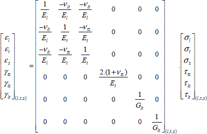
Looking at the issue within a 3D space, two coefficients obviously remain necessary to describe the behavior of an isotropic material but now a total of nine coefficients are required for the description of an orthotropic material:
In practice, UD composite materials are almost transversally isotropic, i.e. all the directions of the (t, z) plane present the same behavior, and only five constants are required to describe their 3D behavior:
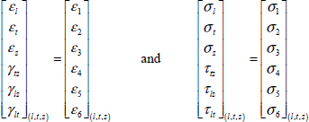
As a reminder, the six elementary stress states are:
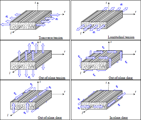
Figure 2.9. The six elementary stress states illustrated in the case of a UD ply. For a color version of this figure, see www.iste.co.uk/bouvet/aeronautical2.zip
Bear in mind that a stress τlt means a force along the l-direction on a face of normal vector t or a force along the t-direction on a face of normal vector l (which is the same due to the symmetry of the stress tensor). And this also works for σt, which strictly speaking should be noted σtt and means a force along the t-direction for a face of normal vector t.
REMARK CONCERNING NOTATIONS.– The notation of the stress and the strain in the form of vector is obviously inappropriate; they are of course symmetrical tensors and therefore present the mathematical properties of symmetrical tensors. In the example in the following chapter, we will see that the rotation rule applies for a tensor and not a vector.
The order of indices can also appear surprising but comes from the direction of the path of the matrix:
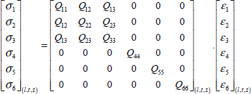
We index the stress or strain from 1 to 6 which gives us, for the stiffness matrix:
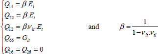
With:
Which in 2D then gives us:
With:


