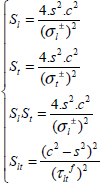
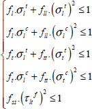
5
Fracture Criteria of a UD Ply
There are a great deal of criteria for fracture of a UD ply under planar stress in the existing literature but they are all based on the five elementary stress states: tension/compression along the longitudinal direction, tension/compression along the transversal direction, and in-plane shear.
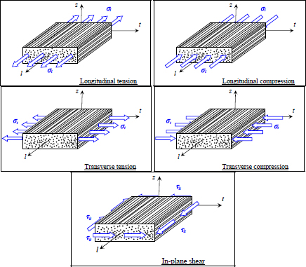
Figure 5.1. The five elementary stress states of a UD ply. For a color version of this figure, see www.iste.co.uk/bouvet/aeronautical2.zip
As mentioned in the previous paragraph, we note a considerable difference between the fracture behavior under tension and compression, unlike the cases of elastic stiffness where this difference is less notable, even though it can reach 20% in certain cases.
5.1. Maximum stress fracture criterion
The maximum stress criterion consists of considering that the UD ply is fractured when one stress reaches a stress limit under tension, compression or shear:
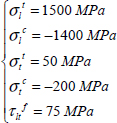
Where σlt and σlc are the tensile and compressive fracture stresses in the longitudinal direction, σtt and σtc are the tensile and compressive fracture stresses in the transversal direction, and τltf is the shear fracture stress. For example, for T300/914 that we touched on previously, we get:
For a biaxial loading with no shear, we get a fracture envelope in the form of a rectangle.
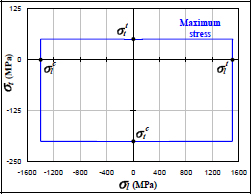
Figure 5.2. Maximum stress criterion. For a color version of this figure, see www.iste.co.uk/bouvet/aeronautical2.zip
We can, for example, use this criterion to determine the fracture point of a ply under tension/compression off of its orthotropic axes.
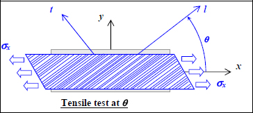
Figure 5.3. Off-axis tensile test of a UD ply. For a color version of this figure, see www.iste.co.uk/bouvet/aeronautical2.zip
We then get:
And the limit value of σx is obtained when one of the five inequalities is no longer verified:
And the value of σx must then be located within the six curves in order to avoid fracture.
On this graph we can observe the different fracture modes. We also note that a small error on the fiber orientation near 0° can cause an important fall in the fracture characteristics, passing from one mode of fiber fracture to a mode of resin shearing. The orientation of fibers will therefore have to be controlled with utmost precision during manufacturing.
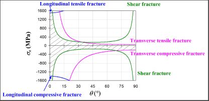
Figure 5.4. Tensile stress limit of an off-axis UD ply. For a color version of this figure, see www.iste.co.uk/bouvet/aeronautical2.zip
The benefit of this criterion is that it is particularly simple and only requires the user to identify five material constants. It also gives an indication as to the encountered mode of fracture, which can give an indication of the modification in the stacking sequence that should be used, or which directions we have to add plies to avoid fracture. This can also nuance the result, as a small fracture in the resin can be accepted as long as it is not critical to the final fracture of the structure.
It nonetheless presents important discrepancies with experimental results that are due to the fact that interaction phenomena between different damage modes are not being taken into account. This is particularly significant for interaction between stress along the longitudinal direction (σl) and the in-plane shear stress (τlt) that is not accounted for, even though it is observed in practice (see upcoming sections).
EXAMPLE (Shear fracture of an off-axis UD ply).– We can also use the maximum stress criterion in order to determine the shear limit stress of an off-axis UD ply:
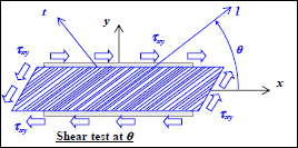
Figure 5.5. Shear test of an off-axis UD ply. For a color version of this figure, see www.iste.co.uk/bouvet/aeronautical2.zip
We obtain the following stresses:
Thus:
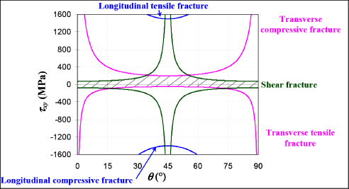
Figure 5.6. Shear limit stress of an off-axis UD ply. For a color version of this figure, see www.iste.co.uk/bouvet/aeronautical2.zip
We note that the tensile fracture in the longitudinal direction never actually occurs.
The effect of the shear sign, which can be surprising, is explained by the fact that a positive shear stress with fibers at 45° will put transverse compressive stress in the matrix, while a negative shear stress with fibers at 45° will put transverse tensile stress in the matrix.

Figure 5.7. Effect of the shear sign on the fracture of a UD ply at 45°. For a color version of this figure, see www.iste.co.uk/bouvet/aeronautical2.zip
5.2. Maximum strain fracture criterion
The maximum strain fracture criterion involves considering the UD ply as broken once one of the strains reaches a strain limit under tension, compression or shear:
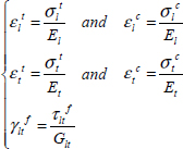
Where εlt and εlc are the tensile and compressive fracture strains along the longitudinal direction, εtt and εtc are the tensile and compressive fracture strains in the transversal direction, and γltf is the shear fracture strain. And we can link the different maximum strains with the maximum stresses by:
This criterion thus gives us the same values as a maximum stress criterion under pure tension/compression but induces an interaction between the two stresses via Poisson’s ratio. It can appear as follows:
We will note, however, that there is a large difference between these two interactions. The first one (1st line of the previous equation) characterizes the effect of the stress σt on the fiber fracture, whereas the second (2nd line of the previous equation) characterizes the effect of the stress σl on the matrix fracture. And while the 1st criterion makes sense and can be observed in practice, the second one does not. As the stress σl passes primarily through the fibers, it will have very little effect on the matrix fracture.
In reality, this criterion is practically never used to characterize fracture in the transversal direction or under shear loading. However, it does make sense for predicting fiber fracture; thus, in the cases of a UD composite, it is common to just use the following:
Obviously, the written criterion does not take into account matrix cracking, which is not necessarily an issue in the case of a real-world stacking sequence (with fibers in all the four directions 0°, ±45° and 90°). The stress in the transverse direction of the studied ply will not be taken on by the latter but rather by its closest perpendicular neighbor (the transverse stress of plies at 0° is supported by plies at 90°, and vice-versa, and those at +45° by plies at −45°, and vice-versa). This notion is fundamental as it allows us to gain some perspective over all the criteria integrating matrix cracking! In evidence, it is often not necessary to study in too much detail the effect of matrix cracking in fracture criteria because in the case of real stacking sequences, surrounding perpendicular fibers will support the loading. Obviously, this is only the case if there are fibers in all the directions (0°, ±45° and 90°), which is the case most of the time; and indeed, that is partly the reason why industrial materials use fibers in all the directions! Having said that, note that studying a fracture criterion on a UD composite (with all the fibers in the same direction) is very practical because it simplifies the problem, though it is generally not an accurate representation of real-world situations. In evidence, the behavior of a ply observed in isolation is very different to its behavior within a laminate. This is something we will touch on again further along in the upcoming sections.
The strain fracture criterion is also used in the case of woven plies, i.e. with fibers along the l- and t-directions woven together (satin, serge, taffetas, etc.). In this case, it makes sense to write a strain criterion in these two directions:
The strain criterion in its general form (equation [5.7]) translates, for a biaxial loading and no shearing, to a fracture envelope in the shape of a quadrangle. Keep in mind that in this figure, the incline of both the lines of the strain criterion characterizing the matrix fracture (the two lines passing through σtt and σtc) makes no sense because stress σl will, in reality, have practically no influence on the matrix fracture (since σl passes through the fibers and not the resin).
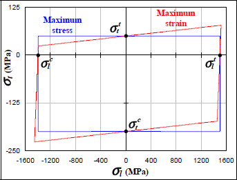
Figure 5.8. Maximum stress and strain fracture criteria. For a color version of this figure, see www.iste.co.uk/bouvet/aeronautical2.zip
We can also use this criterion to determine the fracture of a ply under tensile/compressive stress off of its orthotropic axes.
We then get:
And the limit value of σx is obtained when one of the five inequalities is not verified:
If we compare this criterion to the one with maximum stress, we note that these two criteria are practically equal.
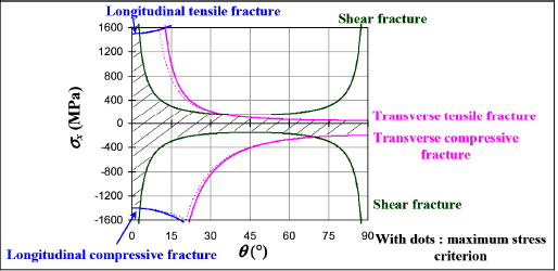
Figure 5.9. Tensile limit stress of an off-axis UD ply. For a color version of this figure, see www.iste.co.uk/bouvet/aeronautical2.zip
The strain criterion presents similar advantages to the previous one, i.e. that it requires five material constants, that it gives an indication as to the fracture mode and that it presents a weak interaction between stresses.
We nonetheless favor criteria such as Hill’s, Tsai–Wu’s or Yamada–Sun’s over this type of criterion, as they better account for the different components of the stress tensor.
5.3. Hill’s criterion
This criterion can be seen as a generalization of the Von Mises criterion. The Von Mises criterion is based on a calculation of the maximum strain energy and appears in 2D:
Where σe is the elasticity limit in tension. As a reminder, this criterion is used to determine the elastic limit of a ductile material by comparing an invariant of the stress tensor, the Von Mises stress, to the tensile stress limit. It is established for an isotropic material and without distinguishing between tension and compression. The Hill’s criterion can be seen as a generalization of this criterion:
And we can easily demonstrate that under tension along the longitudinal direction, we get:
Under tension in the transversal direction:
And under pure shearing:
The last parameter C is determined by considering that under biaxial tension (σl = σt and τlt = 0) the fracture will be reached when σt reaches σtt and we can therefore show that:
In practice, this hypothesis is very difficult to verify because biaxial tests on this type of orthotropic material, with a large difference between behaviors in the l- and t-directions, are hard to interpret. Nonetheless, the influence of this parameter C remains overall quite weak in reality and compared to the other parameters as its value has little impact on the criterion. Furthermore, we can demonstrate that this coefficient can even take on absurd values in certain cases and is often removed from the criterion.
The Hill’s criterion is thus written in its general form as:
With:
This criterion gives the same values as the maximum stress and strain criteria under pure tension/compression but induces coupling between the stress components that accounts for part of the interaction between different damage types.
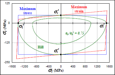
Figure 5.10. Fracture criteria for a UD ply. For a color version of this figure, see www.iste.co.uk/bouvet/aeronautical2.zip
It accounts, in particular, for the effect of shearing on the biaxial stress criterion. For instance, if the shear stress is equal to three quarters of the shear limit stress:
The criterion is thus reduced by as much (Figure 5.10).
We can then use this criterion to determine the stress limit under tension / compression of a UD ply:
We can easily demonstrate that the cross-product term σl.σt will be negligible compared to the shear term in most cases (Figure 5.13).
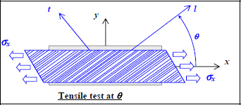
Figure 5.11. Tension of an off-axis UD ply. For a color version of this figure, see www.iste.co.uk/bouvet/aeronautical2.zip
We can then trace the evolution of the maximum stress depending on the angle θ:
We note that the results are close to the strain or stress criteria (which are practically the same) and, in reality, we can demonstrate that this criterion is slightly closer to real-world applications. We can also trace the evolution of the four terms of the criterion to determine the predominant term for each angle.
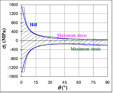
Figure 5.12. Tensile limit stress of an off-axis UD ply. For a color version of this figure, see www.iste.co.uk/bouvet/aeronautical2.zip
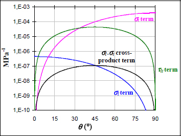
Figure 5.13. Comparison of the four terms of the Hill’s criterion. For a color version of this figure, see www.iste.co.uk/bouvet/aeronautical2.zip
Once again, for low angles, we see that fiber tension/compression is predominant, while for high angles, it’s the matrix tension/compression that is predominant and between the two, the predominant stress is the matrix shearing. As for the cross-term, it is always negligible compared to the others.
The main inconvenience of the Hill’s criterion is that it exaggerates the effect of matrix cracking. For example, in the case of a tensile test on a laminate with a ply at 0° and one at 90°, the criterion gives an early fracture of the 90° ply under matrix cracking (see section 6.4 in Chaper 6). Nonetheless, this premature fracture under transverse cracking of the 90° ply is not too detrimental for the structure, because the stress in that direction is supported by the fibers of the 0° ply (direction t of the 90° ply is also the direction l of the 0° ply). Moreover, it is generally pointless to take matrix cracking into account if there are fibers in all the four directions (0°, ±45° and 90°) to support the loading; this is practically always the case in the industry (this is partly the reason why there are plies in all the directions). Once again, keep in mind that studying a fracture criterion on a UD composite (and with all the fibers in the same direction) is very useful as it helps simplify the problem, but it is often not accurate to reality because the behavior of a ply observed independently is very different to its behavior within a laminate.
To avoid granting too much importance to the effects of matrix cracking in the Hill’s fracture criterion, we can, for example, remove the terms at  and at σl.σt, which then gives us the Yamada–Sun’s criterion, which will be presented in section 5.5 in Chapter 5.
EXAMPLE (Tube under torsion with the Hill’s criterion).–

Figure 5.14. Study of a tube under torsion. For a color version of this figure, see www.iste.co.uk/bouvet/aeronautical2.zip
A thin tube, with a thickness of e and a radius of R, loaded under torsion, is performed from a UD ply wrapped with an angle α. Determine the fracture torque Cr with the Hill’s criterion.
Supposing the tube is thin, we can show that upon first glance only one stress τzθ is generated by torsion, and:
Therefore, in the frame of the UD, we have:
Then the Hill’s criterion:
We can therefore trace the shear limit stress and the respective influence of each fracture mode:
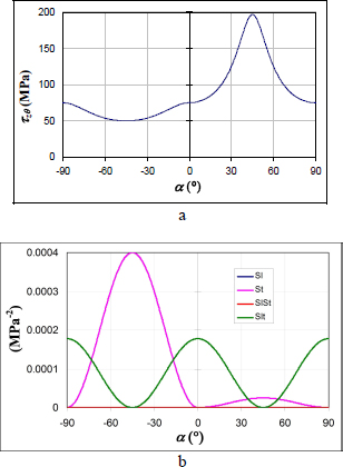
Figure 5.15. Fracture of a UD tube under torsion: shear stress limit a) and influence of the different terms of the Hill’s criterion b). For a color version of this figure, see www.iste.co.uk/bouvet/aeronautical2.zip
We then observe that the tube resists better for positive angle α. For this type of orientation, the torsion loading will cause transverse compression, whereas for negative α, it will cause transverse tension. For example, for α = 45°:

Figure 5.16. Shear fracture of a ply at 45°. For a color version of this figure, see www.iste.co.uk/bouvet/aeronautical2.zip
And for α = −45°:
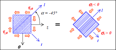
Figure 5.17. Shear fracture of a ply at −45°. For a color version of this figure, see www.iste.co.uk/bouvet/aeronautical2.zip
5.4. Tsai–Wu criterion
Tsai–Wu proposed a fracture criterion that presents the advantage of passing continuously from tension to compression without having to verify the sign of stress. To achieve this, they added a linear stress term to the quadratic term, proposed by Hill, to add information on the sign of the stresses:
Where notation s comes from shearing. As, furthermore, this criterion must not depend on the sign of τlt, then:
If we write this tension/compression criterion along the longitudinal and transversal directions, then under shearing, we get:
And the last coefficient flt could be reached thanks to an additional test. For example, if we performed an off-axis tensile test at 45°, we would then get an expression of this coefficient depending on the stress limit under tension at 45°, σ45t:
Nonetheless, in most cases, this coefficient is of lesser importance and can be approximated in a satisfying manner by (it is even sometimes null):
Thus, the Tsai–Wu criterion:
This criterion presents a high difference with the Hill’s criterion under compression:

Figure 5.18. Limit stress of a UD ply. For a color version of this figure, see www.iste.co.uk/bouvet/aeronautical2.zip
This criterion accounts for the beneficial effect of a transverse compression on the resistance to longitudinal compression. In practice, the fracture under longitudinal compression is due to micro-buckling of the fibers; a transverse compression will indeed stabilize this buckling and delay the compressive fracture.
In practice, it is difficult to conclude on the best of the both criteria under compression/compression. For example, we can show that the stabilizing effect of transverse compression over the longitudinal compression is rather true for a confined ply (surrounded by other plies in different directions) but it is less verified for a thick or isolated UD ply. And, more generally, the sizing of composite structures under compression remains a largely open question and is the object of numerous researches.
Moreover, the Tsai–Wu criterion, just like Hill’s, accounts for the effect of shearing on the biaxial stress criterion. For example, if the shear stress is equal to three quarters of the shear limit stress:
The criterion is then reduced by as much (Figure 5.18).
We can then use this criterion in order to determine the stress limit of an off-axis UD ply.
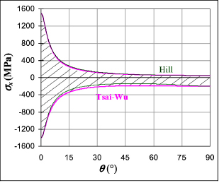
Figure 5.19. Tensile limit stress of an off-axis UD ply. For a color version of this figure, see www.iste.co.uk/bouvet/aeronautical2.zip
Unlike the case of biaxial stresses, the Tsai–Wu criterion is very close to that of Hill’s. This is due to the fact that the shearing part of the criterion quickly overpowers the compression part of the criterion. In practice, this criterion gives relatively good results and is, like the Hill’s criterion, widely utilized.
In 2003, an international exercise (the “World Wide Failure Exercise” [SOD 04]) was carried out to test different fracture models for UD composite. The material used was a UD with fiberglass and epoxy resin. The first comparison was performed with biaxial stress in the plane (σl, σt) (called σx and σy in this publication); unfortunately, there are no experimental results under tension/compression. Nonetheless, we see that the Hill and Tsai–Wu criteria (referred to as the Tsai criterion in this publication) translate the interaction between tension/compression, unlike maximum stress and strain criteria.

Figure 5.20. Comparison of different fracture criteria during the “World Wide Failure Exercise” in the plane (σl, σt) [SOD 04] a) and comparison with the criteria presented here b). For a color version of this figure, see www.iste.co.uk/bouvet/aeronautical2.zip
The second comparison was carried out with transverse tension/compression σt and in-plane shear τlt. We then observe an increase in shear resistance of the UD composite in the presence of transverse compression. This is due to the fact that compression will reduce the tension component induced by shearing (which causes two principal stresses equal to ±τ at ±45° under pure shearing):
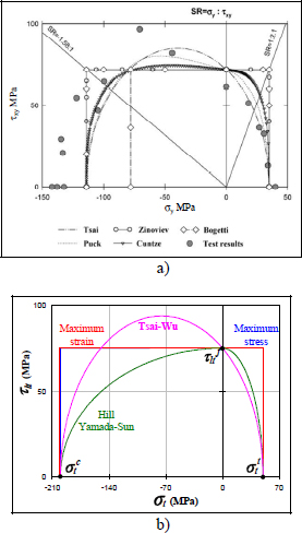
Figure 5.21. Comparison of different fracture criteria during the “World Wide Failure Exercise” in the plane (σt, τlt) [SOD 04] (a) and comparison with the criteria presented here (b). For a color version of this figure, see www.iste.co.uk/bouvet/aeronautical2.zip
Thus:
Yet, the material being more resistant under compression than under tension, the effect of a low transverse compressive stress will be beneficial. Obviously, if we continue to increase the compression (in absolute value), the fracture will appear under compression. This effect is relatively well rendered by the Tsai–Wu criterion (referred to as the Tsai criterion in this publication), even if we can show that this effect is totally fortuitous in this criterion (which is a convenient coincidence).
5.5. Yamada–Sun criterion
To avoid over-accounting for the matrix cracking in the Hill’s criterion, we can, for example, remove the terms at  and at σl.σt, which then gives the Yamada–Sun criterion:
With:
Keep in mind that this criterion mainly focuses on the fiber fracture (even if we can show that the shear term also contains matrix cracking). It must therefore not be used for the fracture of a UD ply on its own but to predict fractures of a laminate. In fact, that is why tracing this criterion in plane (σl, σt) makes no sense (and will therefore not be traced). It would just give us two vertical straight lines:
This doesn’t mean that there is no fracture in transverse tension along the t- direction but that this fracture is not accounted for in this criterion because it is secondary in the case of a laminate. In other words, this criterion can only be used if there exists at least one other perpendicular ply to the load (in addition to the plies in the loading direction).
In the same way, this criterion cannot be used to predict the fracture of an off-axis UD ply. However, it can be used to trace the fracture criterion in plane (σl, τlt), and you will easily be able to demonstrate that we find the same result using the Hill’s criterion (Figure 5.21).
Moreover, it is generally pointless to account for matrix cracking if there are fibers in all the four directions (0°, ±45° and 90°) to support the loading, which is practically always the case in industrial uses (indeed, this is part of the reason why there are always plies in all directions).
Therefore, the Yamada–Sun criterion is the most common in the industry and will be widely used in this book.
5.6. Conclusion
Lastly, to conclude this chapter, never forget that these criteria are never absolute truths: they are models that attempt to translate reality, one which almost always remains far more complex the closer you look at it. In evidence, a fracture criterion is considered correct until proven false or, more precisely, until experimental tests have disproven it (which will happen sooner or later, because a criterion remains true only in a given domain)!

