This chapter explains the basic concepts we’ll be exploring as we build. Note that it aims for strictly practical knowledge. Its goal is to get you acquainted with the laws of physics involved in building working LEGO mechanisms, not to cover everything a practicing engineer or physicist needs to know. So let’s get started with the basics.
Speed describes how fast an object moves. When you think of speed, you likely think about the distance a vehicle can travel within a certain unit of time. We call this linear speed, and we will be measuring it in kilometers per hour (kph).
But there’s another type of speed, called rotational speed, which tells us how fast an object rotates. We’ll need to understand rotational speed, as most LEGO mechanisms are powered by spinning axles, whose rotary motion is transformed into a vehicle’s linear speed using wheels or tank treads. Rotational speed is measured in rotations per minute (RPM). Various types of LEGO motors deliver different RPM, from less than 20 RPM to more than 1,000 RPM.
Torque describes the turning force applied to an object. For example, when a LEGO motor drives an axle, it’s applying torque to that axle. The more torque a motor applies, the stronger the rotation and the more resistance it takes to stop the motor. A motor that has enough torque to drive a 1 kg vehicle, for instance, might be stopped when trying to drive a 2 kg vehicle.
In LEGO Technic, the torque of LEGO motors can be measured in units called Newton centimeters (N•cm). The torque available from a motor is constant for a given power source: For example, the weakest LEGO motors provide 0.5 N•cm of torque, while the strongest ones provide 16.7 N•cm. The situation is different when you drive a mechanism manually—the amount of torque is variable and depends on how much physical strength you apply.
Understanding torque is crucial to understanding the capability of motors and the mechanisms they drive, as well as the limits of LEGO pieces. High torque creates stress that can damage and destroy LEGO pieces. We will learn how to prevent such damage in Chapter 11. Even more importantly, we’ll explore the relationship between torque and rotational speed.
In this book, power refers to mechanical power, which is the product of torque and rotational speed. So torque multiplied by speed gives mechanical power, which is normally measured in watts (W). LEGO motors provide various degrees of power depending on their type, from 0.021 W to 2.38 W. While the concept of power is fairly complex, we will be using it mainly as a faster way to say “speed and torque together.”
The power of a particular LEGO motor is affected by the voltage of its power source (that is, its battery). Most modern LEGO motors are meant to be powered at 9V. While they can run at a lower voltage with lower power, higher voltage can damage them.
When two or more surfaces make contact and slide against each other, friction is a force that resists their motion. You’ll see friction whenever two LEGO pieces are in contact and moving at different speeds. This, in turn, means that every LEGO mechanism is affected by friction, which we have to overcome when we drive a mechanism. Friction dissipates some of the input force we’ve applied to the system, thus reducing both torque and speed.
The amount of friction increases as parts press against each other harder, and it also depends on the type of surface: Smooth, firm surfaces generate less friction than rough, soft ones. Friction can be decreased by separating the surfaces with a lubricating medium, such as a grease.
When building LEGO mechanisms, some notable points of friction are between two meshed gears, between a rotating axle and a piece with a pin hole that houses it, and between wheels and a surface they’re rolling on. Large amounts of friction, resulting from a large number of moving parts, can render a mechanism useless and wear down or even damage LEGO pieces. (Of course, frictional forces are also present in static, nonmoving connections between LEGO pieces, which is why they stick together.)
Traction, also called grip, describes the maximum frictional force that can be produced between two surfaces before they slip. We will be using the term when discussing tires—tires with good traction don’t slip over a surface as easily as tires with poor traction.
Traction depends primarily on the hardness and shape of the tires as well as the type of material that the tires are made of. For example, rubber tires always have better traction than solid plastic wheels because rubber is soft and sticky compared to hard plastic. The differences in shape come down to the profile of the tires and their type of tread. Traction is better when a tire contacts the road’s surface over a large area, and a tire’s profile and tread determine how much of a given type of surface it contacts. As Figure 1-1 shows, tires that have a flat profile and a small, shallow tread have a larger area of contact on flat, smooth surfaces than tires that have a round profile and a large, deep tread.
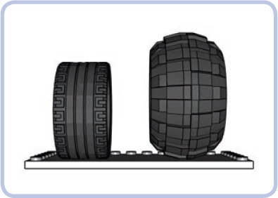
Figure 1-1. A tire with a flat profile and small tread (left) has better contact with a flat surface than a tire with a round profile and large tread (right).
On the other hand, tires with a round profile and a large, deep tread have better contact with irregular, loose, or muddy surfaces. This is why the first type of tire is typical of sports cars designed for roads, while the latter type of tire is typical of off-road cars designed for rough terrain. Finally, the width of the tires also matters simply because wider tires can contact surface over a larger area.
In most cases, you want your tires to provide as much traction as possible. One exception is when you want your tires to slip, for example, to make your vehicle drift. The LEGO 8366 Supersonic RC set comes with two sets of rear tires: one with rubber tires for regular driving and one with solid plastic for drifting.
Rolling resistance describes the resistance generated by rolling an object on a surface, and it is particularly important for wheels. Solid wheels have similar rolling resistance, but for wheels with tires, it varies a lot depending on the tires’ characteristics.
Tires that are soft and wide, such as the one shown in Figure 1-2, generate more rolling resistance than tires that are hard and narrow. The resistance also depends on the vehicle’s weight because weight deforms the tires, increasing their rolling resistance. Finally, the type of surface the wheels are in contact with affects the resistance. Smooth, flat, firm surfaces—such as asphalt or glass—lower the rolling resistance, while loose, boggy, soft, and sticky surfaces—such as sand, mud, or grass—increase it.
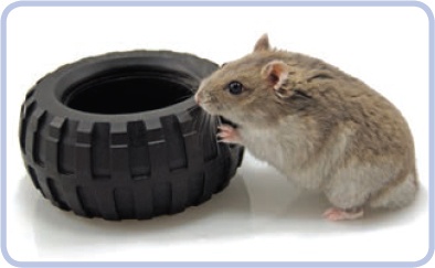
Figure 1-2. Typical off-road tires, which are soft and bulging, have particularly high rolling resistance. Apparently, they make up for it with their flavor.
Rolling resistance is an important factor when choosing wheels and tires, but it is usually less important than traction. There are only a few types of LEGO tires whose rolling resistance is a serious concern, so in most cases you will find improved traction worth a little more resistance. Good traction almost always comes at the cost of extra rolling resistance.
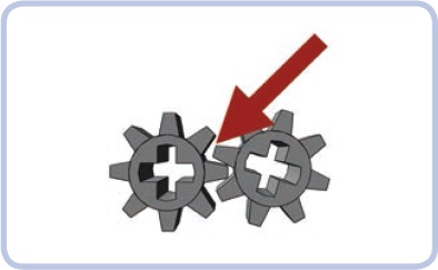
Backlash describes the gaps between mating components, such as two gears, as shown in Figure 1-3. Practically every LEGO Technic connection has some backlash, and too much backlash is highly undesirable. When you start, stop, or reverse a mechanism, backlash will create a delay in the motion between its input and output. High backlash results in a longer delay, making the whole mechanism inaccurate and sluggish.
While building, remember that the backlash of many moving parts sums up, meaning that it accumulates over the entire mechanism. So a mechanism with four gears will have more backlash than a mechanism with two gears. One way to reduce backlash is to make your mechanism as simple as possible, and another is to replace high-backlash components, such as gears, with low-backlash ones, such as pneumatic cylinders (see Chapter 9) or linear actuators (see Chapter 13).
Efficiency describes how much of the power we apply to a mechanism is actually used and how much is dissipated to forms of friction. It is usually expressed as a percentage: For example, a 50 percent efficiency means that a mechanism effectively uses half of the power delivered to it and the other half is lost.
In LEGO mechanisms, efficiency is generally low because LEGO pieces are simple and lack sophisticated mechanical solutions designed to lower friction, such as ball bearings. It is difficult to accurately measure the efficiency of any LEGO mechanism. Instead, we should focus simply on keeping the friction as low as possible.
The only way to improve efficiency is to reduce friction in our mechanism, and the simplest way to do reduce friction is to limit the number of moving parts. Weight is also an important factor because heavy moving parts generate more friction than light ones; size is a factor, too, as larger parts are heavier. In general, the simpler and lighter the mechanism, the more efficient it is.
At this point, we should have a good understanding of the basic physics and engineering concepts that apply to various constructions. Next we’ll focus on issues related to vehicles. Since vehicles form the vast majority of both LEGO Technic sets and custom builds, we will be referring to these concepts throughout this book.
A driveshaft is a mechanical component, usually an axle, that transmits power from the motor to a mechanism. It connects—sometimes not directly—two components: one that generates power and a second that receives it. A typical car, for example, has a single driveshaft that connects its gearbox to one or both of its axles. In other words, the driveshaft connects the engine indirectly, through a gearbox, to a receiving mechanism, which in this case is the wheels.
Driveshafts can also incorporate universal joints or extendable sections, as shown in Figure 1-4. These incorporated pieces allow for variations in the alignment of and distance between the power input and the receiving mechanism.
The drivetrain, also called a powertrain, is a group of components that generate power and deliver it in a vehicle. This group typically includes the motor, transmission (also known as a gearbox), driveshaft, axles, and final drive (the wheels, tracks, or propellers). While components in the middle of a drivetrain may vary—for example, there may be no transmission—the ends of the drivetrain remain the same: One is the propulsion motor (or motors), and the other is the final drive.
The driveline indicates the three final components: the driveshaft, axle, and final drive. In other words, the driveline is the drivetrain minus the motor and gearbox. If you consider a regular bicycle, the drivetrain would include the bicyclist (acting as a motor), pedals, gears, the chain, and the rear wheel as the final drive. The driveline, on the other hand, would include just the chain and the rear wheel.
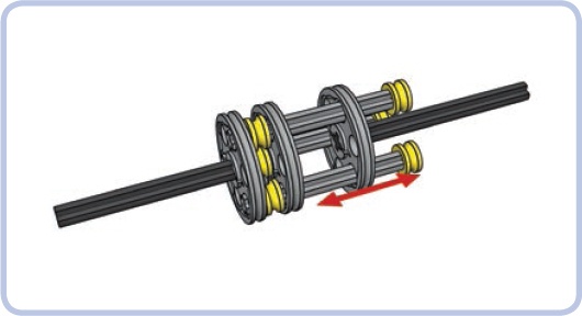
Figure 1-4. An extendable driveshaft section, consisting of two axles with three wedge belt wheels (the thin grey discs) and another three axles inside them. The three axles transmit rotation to all the discs, and these axles are able to slide through the single disc shown on the right, effectively changing the driveshaft’s length even as it spins.
When we talk about the steering lock in this book, we aren’t referring to a physical lock you put on your steering wheel to prevent theft. The steering lock is the maximum steering angle—that is, the maximum angle to which wheels on a steered axle can be turned. Usually the greater the steering lock, the better, as it allows the vehicle to make tighter turns. However, a very large steering lock can be undesirable because it enables the vehicle’s direction to change very rapidly, making the vehicle less stable and exerting significant stress on parts of the steering system. See Figure 1-5 for a model with a large steering lock.
The turning radius, also called the turning circle, is the radius of the smallest U-turn the vehicle can make. Note that a vehicle’s bodywork often overhangs the wheels, and the turning radius can be measured including its frame (a wall-to-wall turning radius) or without the frame, taking only the wheels into consideration (a curb-to-curb turning radius).
The turning radius is affected by several factors, including the maximum steering angle, the wheelbase, and the number of steered axles. The smaller this radius is, the better for the vehicle, as it can maneuver within tighter spaces. Note that certain vehicles, like tanks and other tracked vehicles, can turn in place, meaning they have a turning radius of zero.

FWD, RWD, 4×4, 4WD, and AWD are abbreviations referring to the arrangement of driven axles in a vehicle. For example, a car with only the front axle driven has FWD, or front-wheel drive, while a car with only the rear axle driven has RWD, or rear-wheel drive.
A 4×4 vehicle is an automobile whose four wheels are all driven. With LEGO 4×4 vehicles, we are dealing with a so-called 4WD, or four-wheel drive, where the motor’s power is split equally among all wheels. Real 4×4 vehicles can also have something called AWD, or all-wheel drive, where the power distribution is constantly adjusted to driving conditions by electronic components—something that is extremely difficult to achieve with LEGO pieces.
Note that a third number can be added to the 4×4 description. For example, an SUV or Jeep is 4×4×2, which means four wheels total, four wheels driven, and two wheels steered. Such descriptions are particularly important for multi-axle vehicles, such as mobile cranes and armored personnel carriers, which have many axles driven and steered. For instance, many small armored personnel carriers are 6×6×4, which stands for six wheels, all of which are driven and four of which are steered.
Weight distribution, and in particular whether a vehicle is front heavy or rear heavy, can greatly affect the performance of a vehicle.
Weight distribution primarily affects traction and thus handling. Imagine a car with two axles: one steered in front and one driven in rear. If this car is more front-heavy, it will have better steering traction because its front wheels will have more weight on them. If this car is more rear-heavy, it will have better acceleration because its rear wheels will have better traction with more weight on them.
In four-wheeled vehicles, weight distribution is described as number:number or number/number. For example, a 40:60 weight distribution means that 40 percent of the vehicle’s weight rests on the front axle and 60 percent on the rear one. In off-road cars with 4WD, 50:50 weight distribution is considered ideal, while high-performance race cars with central engines often have more weight in the back.
Weight distribution is also important for tracked vehicles. Since tracks have poor traction on smooth surfaces, weight distribution significantly affects how a tracked vehicle turns and how it climbs obstacles. For example, a front-heavy tracked vehicle won’t be able to turn in place because its center of rotation will be moved forward. But this type of vehicle will be good at climbing up hills because its front end will have better traction.
The center of gravity is the central point of an object’s weight distribution. It can be located in the actual center of the object—in the case of a solid ball, for example—or elsewhere. The location of the center of gravity determines the object’s likelihood of falling over, which is greater for objects with a high center of gravity than for ones with a low center of gravity. In other words, the low center of gravity makes objects more stable.
With LEGO vehicles, the center of gravity is greatly affected by the location of a vehicle’s heaviest components, such as battery boxes, and it should always be as low as possible. This is why, for example, builders of off-road vehicles, which need to be very stable, always try to locate battery boxes low in the chassis.
Ground clearance, also called ride height or simply clearance, is the distance between the underside of the chassis and a flat, level surface the vehicle is standing on. It determines the height of obstacles the vehicle can drive over without scraping them with the chassis, as shown in Figure 1-6. Ground clearance depends primarily on the suspension system.

Figure 1-6. The green arrow indicates this simple buggy’s ground clearance. Note that the ground clearance is usually measured in the center of the vehicle as seen from front or rear, because this part is most likely to contact obstacles.
High ground clearance allows a vehicle to negotiate bigger obstacles but makes it taller and less stable due to a higher center of gravity. Low ground clearance improves stability but reduces the ability to drive over rough terrain. High ground clearance is therefore typical of off-road vehicles, whereas low ground clearance is common in sports cars because they are designed for flat roads and benefit from good stability, which allows them to make turns at higher speeds.
Now that you have these basics down, let’s start putting them into practice!