Use cases[197] for data centers can be as varied as the applications that reside in the data center. To tie together some of the concepts from earlier chapters, we’ll look at examples that demonstrate:
A hierarchical application with a low degree of multitenancy in an orchestrated overlay
A DevOps alternative to overlay orchestration
SDN in a big data application (application-driven network control)
NFV/service chaining both in and outside the data center
The roles played by data center infrastructure can be pure IaaS, PaaS, SaaS, or any combination of these services.
A typical vertical industry service center that primarily provides SaaS services (a data center for specialized information management, for example, medical records management, human resources outsourcing, etc.[198]) might envision several client types, with varying levels of commonality (the variance comes in how they might connect to the outside).
Their client’s commonality comes from the fact that all assume some level of public/Internet access to the SaaS service and that access will always traverse an ADC (the ADC does some fundamental security, and load balancing).
The operator’s primary concerns are scale, ease of operations, and security. In the case of the latter, all the systems are to be protected from worms, viruses, malware, and other types of intrusion.
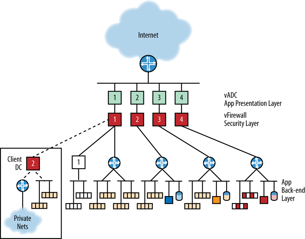
Figure 11-1. A conceptual specialized service center (data center). Tenant type 1 is completely virtualized with two VM pools, the service app (yellow) and their own app (white). Tenant type 2 has off-premise instances of the app as well as private network connectivity. They also have their own non-virtual apps and DBMS hosted in the DC (blue). Tenant type 3 has the service app (virtual) and its own non-virtual app and DBMS (orange), which are only accessible via the Internet. Tenant type 4 is using the DC for infrastructure (IaaS) only (dark red).
As shown in Figure 11-1, the first client type has multiple virtual networks within the data center. The first serves the primary service center application/data management function, and the others are outsourced networks for other purposes (thus, the client subscribes to a combination of IaaS, PaaS, and SaaS within the data center). The client also manages its own VMs inside its own network, which can attach to the data center.
Addressing from the client network is extended into the service center. This fits the VPN client model.
There are four discrete flow types:
Server-to-server within a segment.
Server-to-server between segments (via the gateway)
User traffic from the outside via the vADC and vFirewall (the firewall can be inside or outside the gateway)
Server-to-server from the client network VMs within the service center to the tenant network VMs, traversing one or more (local and/or remote) firewalls.
The second client type shown in Figure 11-1 extends the service center application (SaaS) to its site and may also have a combination of virtual and physical assets in the data center (the virtual assets are managed via the SDN/Orchestration system). In this scenario, the virtual machine management extends to the tenant’s own facility.
This mode of operation could fit the cloud-bursting model.
The flow types include #1 and #3 from the former scenario (except for true cloudburst, the flow in #3 would first use the client site VMs before overflowing into DC VMs). Flow #2 is slightly modified because it is between a VM and a physical device (which many not be managed by the VM orchestration system). Flow #4 varies slightly in that it can be between local and remote VMs, but the DC provider manages them all.
This second scenario introduces two new flows:
From tenant VMs in the service center to the machines/VMs in their private network (an extra gateway traversal)
From remote-but-managed VMs to remote machines in the private network
The third scenario in Figure 11-1 is Internet-access-only, whether for IaaS, PaaS, or the service center specific applications (SaaS).
And finally, the fourth scenario shown in Figure 11-1 is like the second; only the private network is not on a client premise, but rather within the service center (an extra-net connection). Management of that network may be partitioned from the service center operator or provided by the operator.
What this actually looks like in a data center is a lot less idealized. There could be separate storage, host, management (both out-of-band monitoring and image load/stand-up), and vMotion networks. To realize the benefits of pooling, the network will become an overlay-heavy physical infrastructure (which is hard to depict in a small picture like Figure 11-2), as clients get more randomized on that infrastructure.
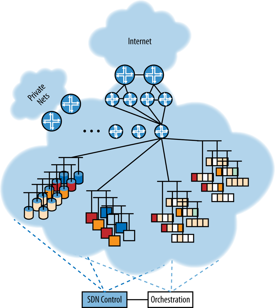
Figure 11-2. What the service center actually looks like—interspersing of physical, virtual, and storage placements enabled by overlay virtualization (hard to depict here, but each color would be a spiderweb of overlay tunnels)
In any of the overlay approaches, when the first virtual machine of a given tenant is instantiated on a server, the following steps need to take place (as shown in Figure 11-3):
A new virtual machine is instantiated.
A logical bridge for the tenant is created in the vSwitch.
The new virtual machine is attached to the logical bridge using a virtual Ethernet interface.
If it doesn’t already exist, a tunnel is instantiated from the server to each of the other servers in the data center that has at least one virtual machine for the same tenant.
A virtual Ethernet interface is created on top of each tunnel to represent the tenant ID and attached to the logical bridge (see Chapter 6 for per-encapsulation specifics on how the tenant ID is transmitted/expressed).
Apply services to the virtual interface of the VM such as QoS, firewall policies, access lists, etc.
Note
When an additional virtual machine for the same tenant is instantiated on that same server, only steps 1, 3, 5, and 6 need to take place.
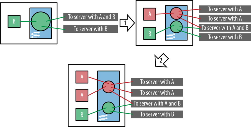
Figure 11-3. Adding a virtual machine for a tenant on a server; add first VM for tenant (1); add additional VMs (2)
It is the responsibility of the SDN controller to create the logical bridge, to create the tunnels, to create the virtual Ethernet interfaces, and to attach the virtual Ethernet interfaces to logical bridges. There needs to be some sort of signaling protocol between the SDN controller and the server to signal these operations, as shown in Figure 11-4. We discuss this in detail in Chapter 4. In general, the SDN controller is only responsible for the network aspect of the data center. It performs the low-level network operations based on high-level instructions from the orchestrator. The orchestrator is responsible for the overall operation of the data center, not just the network but also compute, storage, and services.
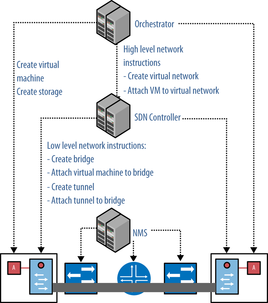
One important observation is that neither the orchestrator nor the SDN controllers touch the physical network; they only touch the servers. In the overlay model, adding a tenant or adding a virtual machine to a tenant does not involve any changes to the physical network. It is the responsibility of the Network Management System (NMS) to manage the physical network. The NMS needs to interact with the physical network when switches are added or when servers are added, but not when tenants are added or virtual machines are added. This is clearly an advantage of the overlay model. The physical network is very stable and as a result more reliable; all the dynamic changes related to tenants are dealt with in the virtualized network.
In addition to the state related to tenants and VMs (namely tunnels, bridges, and interfaces), there also needs to be forwarding state on the servers for each tenant, including:
A MAC address table for each tenant bridge in the vSwitch
An ARP table for each VM
This is illustrated in Figure 11-5.
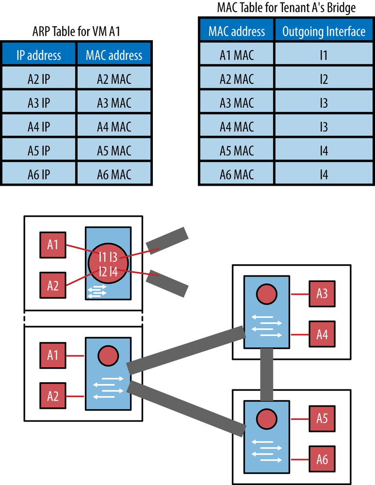
The MAC table can be filled in two ways: data-driven learning or control-plane signaling.
The data-driven learning approach uses the same mechanism as normal (i.e., non-overlay) switched networks. Frames with an unknown destination MAC address are flooded across the entire tenant network. By observing the source MAC address and incoming interface of Ethernet frames, the switch creates the MAC address table. It also creates an ARP table. The ARP table that is used to map IP addresses to the MAC addresses is created through the broadcast of an ARP request across the entire tenant network. The data-driven learning approach has scaling and stability problems. The need for STP can be eliminated or reduced by using split-horizon on the tunnel interfaces (never forward a frame received over a tunnel to another tunnel). The data-driven learning approach has challenges dealing with VM mobility in that it must be implemented in such a way that can react quickly enough to VM moves to reprogram all of the information just described.
In the control-plane signaling approach, the SDN controller populates the MAC address table using some signaling protocol (e.g., OpenFlow or XMPP). The controller has all necessary information: it knows the location, MAC address, and IP address of each VM. The SDN controller is aware of VM moves and can reprogram the MAC address table accordingly. The SDN controller cannot use a signaling protocol to fill the ARP table in the VM because the VM runs application software and cannot be assumed to contain a signaling agent to communicate with the SDN controller. One option is to use the normal ARP resolution process and accept the flooded ARP requests. Another option is to implement an ARP proxy in the vSwitch, which intercepts the ARP requests and tunnels them to the SDN controller.
Reviewing the basic advantages of the overlay approach (from Chapter 6):
No tenant state in the physical switches. Specifically, the physical switches do not contain any MAC addresses of tenant virtual machines. In the absence of overlays, the core switches contain all MAC address of all VMs of all tenants.
If overlay solution uses layer 2 over layer 3 tunneling, there is the option of making the physical network a layer 3 routed network instead of a layer 2 switched network. This improves bandwidth utilization and performance (natural multipath support). A layer 2 physical network uses STP and needs a protocol like TRILL to support multipath.[199]
By terminating the tunnel in the hypervisor (e.g., versus using VEPA on the ToR), tunnel state is distributed among the hosts and their hypervisors. A DC provider presented the following metrics that we can use in discussing the implications of overlays on tunnel state:
Most examples of widely used ToRs today will support 48 hosts.
Each host currently supports an average of 20 virtual machines.
The typical tenant will have four or five VMs.
A tenant may also need to interface with an appliance (e.g., firewall) and/or a gateway, as in our example.
Assuming some level of redundancy of the appliance/gateway and a worst-case VM distribution for the tenant, where every VM on the host is unique, a quick calculation of the number of potential tunnels would be in the low hundreds (about 160—8 tunnels per VM, 4 tunnels to other hosts in the group, 2 to redundant firewalls, and 2 to gateways, 20 VMs). The number of flows mapping onto those tunnels can be an additional but currently manageable scale multiplier (not always a 1:1 correspondence).
As you add VMs per tenant and create a very highly meshed fabric that is further complicated with technologies like LAG and attempt to exploit that fabric through multipath, the number of tunnels/links per host can scale quickly. Of course, this worst-case scenario is also based on the assumption that the hosts were capable of (and desired) full mesh connectivity.
In our specific case, many of the flows must first traverse a firewall or gateway because there are fewer intra-segment flows anticipated. This is particularly true of the third tenant type in our service center example (see Figure 11-1), where Internet access may be only for the service center application. In these cases, the total tunnels in the host hypervisor approach the number of VMs on the host with some small multiplier for redundancy scenarios (similarly, the mapping of flows to these tunnels would scale as noted previously).
Either way, the worst-case scale for this provider’s average tenant size and flows is supportable on the current generation of COTS hosts. On the other hand, the tunnel state could be at least order of magnitude larger (potentially 48X) if we originate the overlay from the ToR switch. This tunnel scale is achievable in some network silicon, but at a cost.[200]
It remains to be seen if the next generation of servers/CPUs and its accompanying increase in VMs supported will fit into the forwarding space of the hypervisors, but the expectation is that it should be manageable. The bound would not be processing power, which continues to grow every day, but instead process space within the hypervisor.
If the number of client types and the scale is not overly large (where “large” is objective), the operator may not need an orchestration-driven SDN solution. The DevOps option of using a template-based, build-out tool like Puppet, Chef, Cobbler, or Ganglia, may be appropriate.
The strengths of these tools developed around image/role and server management, including address assignment and network configuration (for both bare metal and virtual hosts). For example, when using Puppet, the role of the Puppet Master is to assign nodes (devices) into classes (e.g., web server, database server, etc.). Each class definition describes the catalog of resources needed on device (e.g., Apache, MySQL, etc.). The resources describe what to do, not how to do it.
Applying this concept to networking, the resources would be interfaces, VLANs, and so on. If the operating system of a traditional network element supports a Puppet client/agent, interesting solutions can emerge. For example, if the scale of the data center operation was small enough to fit within the scope of VLAN separation (not requiring an overlay), then extensions to Puppet can be used to configure VLANs on ports and trunks appropriate to such an architecture.
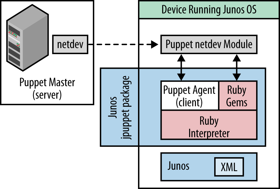
Juniper Networks and Arista Networks have both extended Puppet to support agents in their respective OS(s).[201] In our example shown in Figure 11-6, the (Juniper Networks) solution consists of two files:
The first, /netdevops/netdev_stdlib, includes Puppet type definitions for netdev resources. Netdev is a vendor-neutral network abstraction framework created by Juniper Networks and made freely available on GitHub.[202]
The second file, juniper/netdev_stdlib_junos, uses Junos OS-specific code that implements each of the types defined by
netdevop/netdev_stdlib.
This latter file is necessarily vendor-specific, working around the current lack of common data models for these services.[203]
This combination supports the following types:
- netdev_device
Models the properties of the network device.
- netdev_interface
Models the properties for a physical interface. The properties for a physical interface are managed separately from the services on the interface.
- netdev_l2_interface
Models the properties for layer 2 switching services on an interface. The services for a layer 2 interface are managed separately from the physical interface.
- netdev_lag
Models the properties for a link aggregation group (LAG). The properties for a LAG are managed separately from the physical member links and services on the interface.
- netdev_vlan
Models the properties for a VLAN resource.
For a user of Puppet, assignment of VLANs to a host would mean
editing the netdev section of the manifest for a host.
The Puppet master will compile the manifest and the changed code can be
(periodically) downloaded by the host/element (via SSL).
For example, deploying application foo on switch
fooswitch1 in bar.com (assigning foo to
a port and a trunk with VLAN 100 to talk to other
foo-like servers) would look something like:
node "fooswitch1.bar.com" {
   netdev_device { $hostname: }
   netdev_vlan { "Foo-net":
      vlan_id => 100,
   }
netdev_vlan { "Native":
      vlan_id => 103,
   }
   netdev_l2_interface { 'ge-0/0/19':
      untagged_vlan => Native,
     description=>"local foo host port"
   }
   netdev_l2_interface { 'ge-0/0/20':
      description => "trunk Link from local ToR",
      untagged_vlan => Native,
      tagged_vlans => [ Foo ],
   }
}
Though this example is relatively static, most DevOps template/script languages are highly parameterized and can use class definitions. The Puppet framework enables large-scale changes to devices by simply changing the class definition on the Puppet master.
Our example with variable definition might be as follows:
$vlans = {
   'Foo'    => { vlan_id => 100, description => "This is a foo vlan, just updated" },
   'Native' => { vlan_id => 103, description => "This is a native vlan" },
}
And this might be its corresponding class definition:
class foo_switch {
   netdev_device { $hostname: }
   create_resources( netdev_vlan, $vlans )
   $db_port_desc = "This is for foo-ap"
   $db_ports = {
      "ge-0/0/0"  => { description => "${db_port_desc} ge0" },
      "ge-0/0/1"  => { description => "${db_port_desc} ge1" },
}
   $db_port_settings = {
      untagged_vlan => Native,
      tagged_vlans => [Foo]
   }
   create_resources(netdev_l2_interface,$db_ports,$db_port_settings )
}
And its corresponding invocation call might look something like this:
node "fooswitch1.bar.com" {
   include foo_switch
}
While this example is limited by the vendor contributed library extensions in Puppet to layer 2 operations, there are no real limitations on the functionality that could be exposed in the future. It should be noted that similar functionality limitations exist for alternatives like OpenStack Quantum, though this should be addressed in a subsequent release of the API. That is, it’s just a question of the effort the vendor puts in to support and expand the API over time to enable layer 3 services, overlays, or services.
In Data Center Orchestration, the operator offers services that include the use of virtual appliances (e.g., firewall). In general, the use of these appliances can be orchestrated in a way that allows for simple traversal of a pipeline of operations where logical interfaces representing both an ingress and egress from the tenant network create a simple traffic flow pattern. This is in fact at the heart of network function virtualization (NFV) and how those functions are chained together using a concept called service chaining (Figure 11-7).
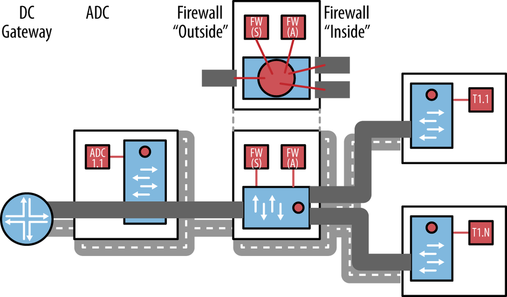
Figure 11-7. Our data center service chain; there could be additional complexity in the overlay derived from the high availability strategy (active and standby VMs shown, but active/standby devices are more likely from a throughput standpoint)
The meta concept around NFV is that in the definition of the service for all the tenants in our example is one fundamental service chain: ADC-Firewall for all traffic ingress from the Internet.[204] It is actually two, in the case of the VPN/private network cases. The actions by the appliance are either forward, modify-and-forward, or drop. No additional logic is required. No metadata is necessarily passed from one service element to another. There is no significant branching logic in the chain.
Service chains are generally constructed by some controlling or orchestration entity (i.e., an SDN controller). This entity is responsible for the provisioning (i.e., placement) of the services, and then the chaining of them together. The actual per-tenant configuration of the services such as firewall and gateway can vary but need to be maintained by the NFV controller or orchestrator. The transparency of the provisioning effort at this point in time may depend on the orchestration vendor selected and the firewall product deployed. If they are from the same vendor, there is a good chance that flow through provisioning (transparent) is possible. If they are not, some degree of transparency could be maintained through a higher-level broker (OSS) that interfaces with both the SDN controller and the firewall vendor EMS/provisioning entity. The same could be said about any appliance/service-chain relationship (today).
The complexity in the chain in this example will be derived from high availability and/or a load balancing use case that we will discuss later in the book (creating the bowtie seen in Figure 7-10 in Chapter 7). We should note too that this is not meant to imply that all data center service chaining is fundamentally simple, as some configurations can be quite complex to not only provision correctly, but to maintain over time.
Much more complex chains may evolve, particularly outside the data center in the decomposition of integrated network platforms, particularly those that deal with broadband subscription or mobility (e.g., EPC). Of course, it’s the vision that many of these services will move into the DC.
The reasons behind this are the per-subscriber nature of the service customization:
For a typical mobile subscriber, there can be multiple chains: HTTP traffic (L4 filtering, ADC, Media Optimization, Caching, CGN, FW—stateful and stateless), Peer-to-Peer (DPI, CGN, FW—stateful), VoIP and others—some of which may require session proxy. (Ad hoc analysis of current mobile service providers potential use cases has shown an average of 7 to 10 possible service chains.)
Service chain characteristics depend on business aspects (e.g., sponsored charging for traffic toward a specific application server) and not on network characteristics.
Service chains are dynamic and personalized.
Because of the per-subscriber nature of traffic treatment, some metadata or context may need to be associated with the chain OR
What is typically referred to as the Gi LAN (based on the 3GPP interface nomenclature) or service LAN is currently a series of value-added services with traffic steering based on VLAN. This is originally set by APN matching and subsequently reset through DPI action—advised by policy interaction (Figure 11-8).
One of the reconfiguration options for this service would be to send the traffic to a next generation proxy. However, WiFi tethering is increasing in the mobile space, so a lot of laptop traffic is going through the proxy, which is inefficient, costly, and adds latency.
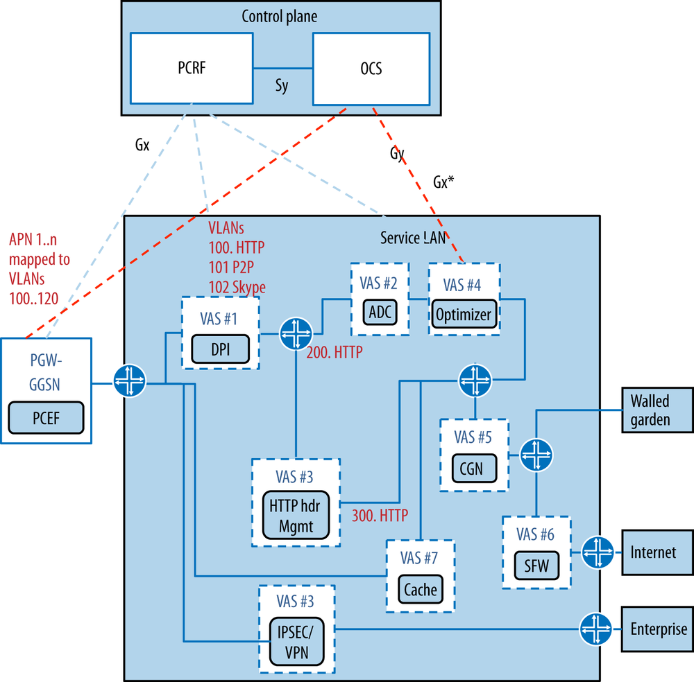
Figure 11-8. Typical mobile service LAN with a collection of value-added services (VAS). The different APNs are mapped to VLANs. Further remapping may result from DPI (e.g., VLAN 200, 300 branches).
Traffic steering (in the SDN sense, given current tools) is layer 3, making options like steering based on URL impossible. Yet, this is the granularity required to differentiate which VAS different customers might traverse.
A reasonably scalable solution might be a PCC-controlled subscriber binding to a service chain. In the case of OpenFlow control, a combination of VLAN ID per service chain for local/legacy VAS, and data center VAS with additional MAC rewrite in the encapsulation to direct to a Next Hop (in WAN and data center)—all done through flow mods directed by the URL/IP to service chain mapping in orchestration (Figure 11-9). This can be extended/scaled to a VxLAN or GRE encapsulation by replacing the more intricate (and potentially limiting) VLAN/NH-MAP flow modifications of OpenFlow with a routable tunnel encapsulation (flow to VNID to service chain mapping). Some legacy VAS may still require VLAN mappings to and from the tunnel overlay via a vendor-specific gateway or within the network element (acting as a gateway on behalf of the overlay orchestration). The TDF function allows the provider to leverage existing application-based charging systems and dynamic policy- or business-related service adjustments.
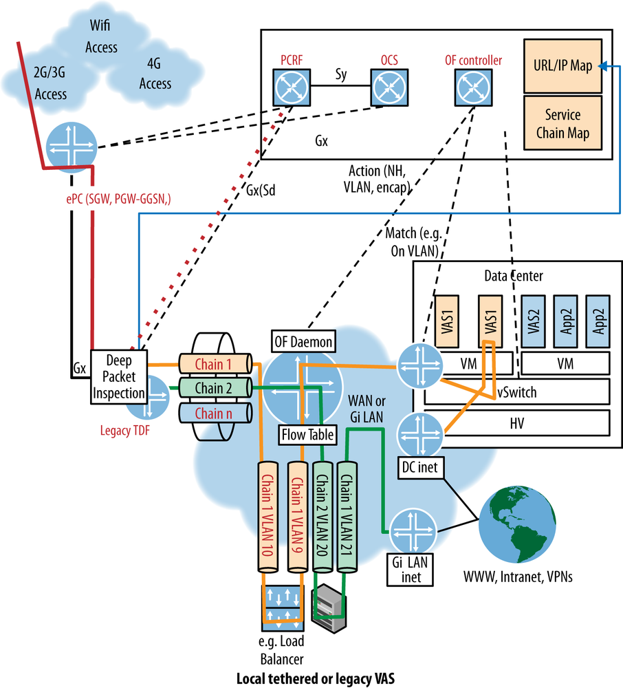
Figure 11-9. SDN control that performs per-subscriber traffic steering. Traffic is identified by TDF (DPI) function. Local/legacy (doesn’t understand tunnels) VAS chained via VLAN, otherwise VAS steering via tunnel overlay.
It also represents a philosophical shift away from the bidirectional conversation between application and network. In this model, the network control reacts to what it is presented with via the policy engine and the DPI sniffer.
The label “big data” represents transition in high performance computing from purpose-built computing (i.e., SUN microsystems, CRAY, etc.) to an approach that takes advantage of the economics of COTS hardware through the use of smaller, cheaper devices that can be clustered together. This is accomplished using divide-and-conquer approaches that dissect computational problems into small chunks both in terms of data and actual computation, and spreads that across those smaller, less powerful but significantly less expensive hardware. It should be noted that adopters of big data techniques have noticed the natural affinity between the topological view and central control of SDN and some big data applications.
In general, big data is not normally a virtualized environment because the hypervisor overhead is unnecessary. Hadoop is one of the most popular of a class of cluster computing architectures for big data that uses an application controller to manage job requests.[205] Hadoop is used for a class of applications called Map/Reduces, which process tremendous amounts of data by breaking the problem (i.e., the data set) into a number of sections/blocks, spread across a number of machines for parallel processing. This system also takes advantage of Hadoop’s distributed filesystem—HDFS.
The main overhead in the application is in distributing the sectioned file, storing and then collecting the results. This is magnified by a redundancy strategy that causes several copies of the same block to be distributed in case one of the compute nodes fails—replication is a hierarchical operation.
The Hadoop architecture has three functional components: clients, masters, and slaves (Figure 11-10). The client is the ultimate end user of the cluster, submitting a job request with a file to manipulate with instructions on how to manipulate/process it and collecting results. The master node in Hadoop has overall responsibility for file distribution and managing the processing nodes. It depends and interacts with two other nodes: the name node and the job tracker. The name node is responsible for the distribution/storage, and the job tracker coordinates the compute.[206]
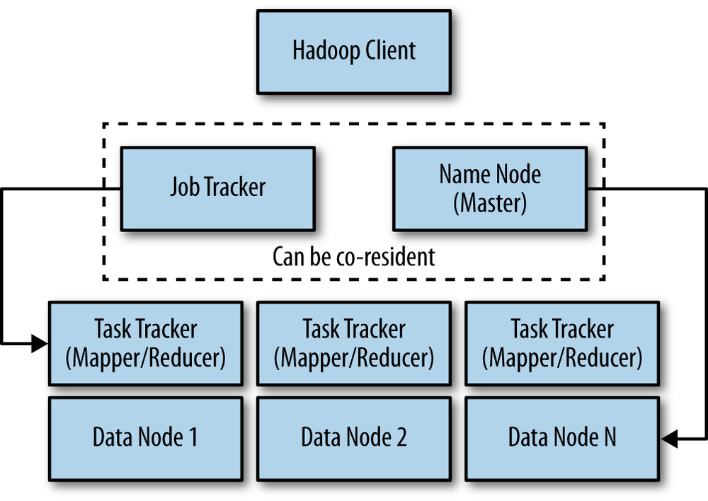
The slaves are called the mappers and take the blocks and process them. The reducers collect and aggregate the results. The job tracker controls the task tracker process and also processes and coordinates jobs submitted by clients. The job tracker talks to the name node to determine the location of the data being processed. The job tracker is also responsible for submitted work to the task tracker nodes that have been chosen to do the work. As a means of redundancy and high availability of the system, the task tracker nodes must ping the job tracker at periodic intervals. If these heartbeat signals are not received after some period of time, the job tracker decides to resubmit the job elsewhere, can blacklist the task tracker, or just remember that this particular node’s performance characteristics for the future because it may only be a temporary condition. It could also denote the start of a host/server failure.
The name node keeps a map of where the file is and to which machines the blocks are distributed. It has some level of topology awareness on its own, in that it understands the relative position of hosts by a manually configured rack number associated with the host by the administrator. The name node then works using algorithms that try to optimally distribute the data to cut down on inter-rack transfers but still maintain separation of the replicates so that redundancy/replication can work.[207]
The problem with this is the manual nature of the configuration (particularly in a large and continually growing/adapting data center) and the less than dynamic nature of the algorithm (there are assumptions about the relative performance in-rack that may not always be true, particularly in the presence of other traffic).
Using an SDN (OpenFlow) controller and a modified version of Hadoop (a modified job tracker and task), an alternative more dynamic version of Hadoop can be realized in a traditional switched/shared Ethernet-based topology (Figure 11-11). For example, a recent study that optimizes the shuffle phase where mappers send results to reducers by using OpenFlow-driven QoS so that the shuffle traffic can consume more link bandwidth has shown promising results.[208]
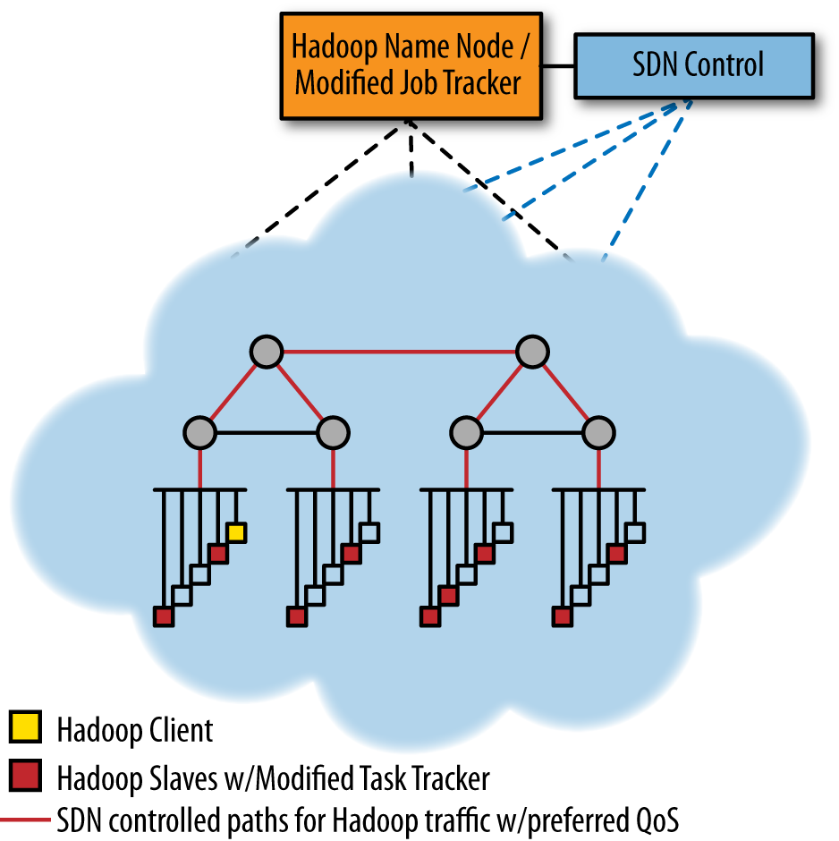
Figure 11-11. Modified Hadoop with SDN control giving Hadoop traffic favorable QoS treatment (in a generic, Ethernet-switched data center architecture)
This solution can be even more attractive when the switching infrastructure is programmable optics. In this case, optimized topology configuration can be implemented as OpenFlow rules in an electro-optical network (Figure 11-12).[209]
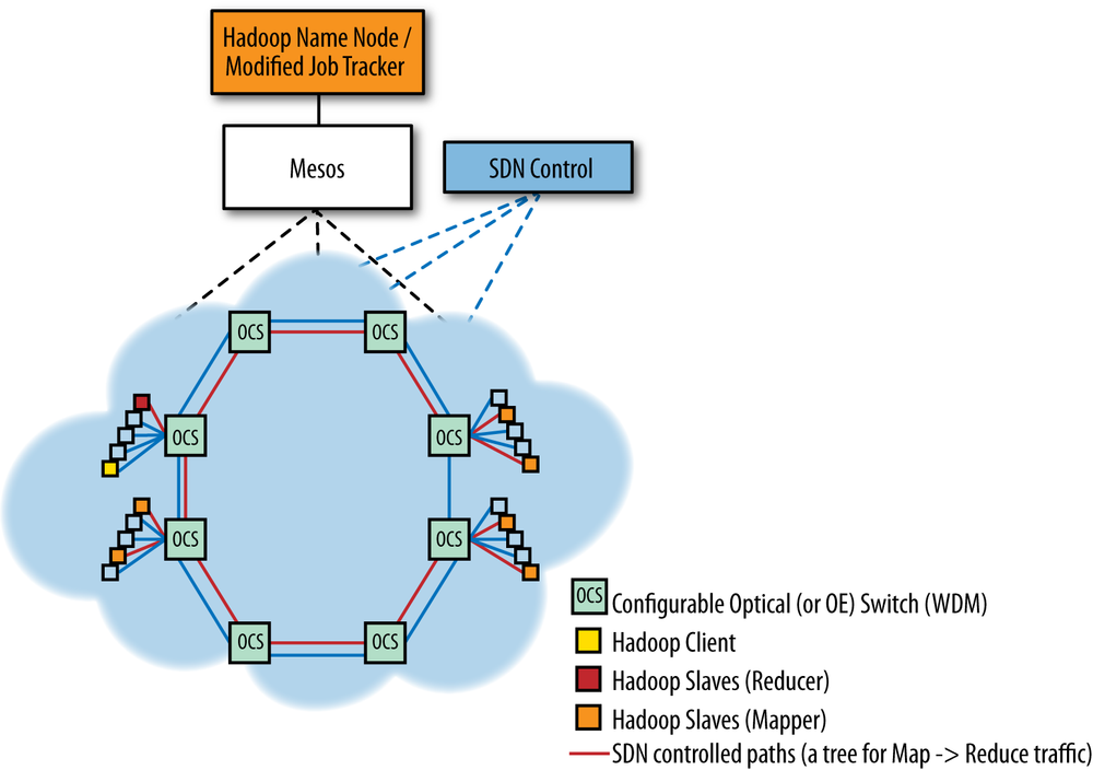
Figure 11-12. Hadoop using an SDN controller (via Mesos, if desired) to create a tree topology for mapper-to-reducer traffic in a network of configurable optical switches
Another recent study[210] in this area shows the flexibility of the combination. Range was derived from multiple tree topologies where reducers were closer to the root than their associated mappers. This information was then used to reduce multihop transfers in very scalable Torus or Hypercube network shapes that were ultimately enabled by changes in the data shuffling strategy.
A further expansion of both of these ideas is suggested by binding the controller to a dynamic resource manager for clusters (e.g., Mesos,[211] which we incorporated in Figure 11-2). By using a manager, the operator can run multiple frameworks in the same cluster to control utilization (particularly for storage) and potentially share data (as opposed to static partitioning).
What we have essentially created is a network-aware application that will attempt to optimize its functions placement or influence their interconnection/plumbing based on network knowledge. This differs in philosophy from optimizations based on network level analytics—application-aware networks (e.g., Plexxi, Helios,[212] OSA[213]) or the previous TDF-enabled mobility NFV example.
Solutions like Plexxi can work both ways, as the Hadoop job tracker/name node could be modified to export the list of nodes in a manner that can be imported as an affinity-map (static) by the Plexxi controller.
Our health services-related data center has multiple target customer scenarios and multiple resulting potential flows (and issues), with some customizable but recognizable service elements (load balancing, firewall, and network gateway).
But data center orchestration doesn’t always have to mean complex, nor does it have to incorporate SDN. To that end, we incorporated a DevOps example appropriate for a simpler, VLAN-based data center deployment.
We ended by focusing on a specific application class—big data. In addition to introducing how SDN can influence big data, we open (and purposely leave open) the discussion about the role of SDN—whether it is to enable applications to be network aware, the reverse, or (potentially) both.
In this chapter, we have attempted to illustrate some common yet useful data center and NFV-related use cases. These topics had to be combined in the examples, as it is hard to separate these topics today. While seemingly theoretical, the use cases are based on real, albeit purposely anonymous, deployments, and public research. Data center orchestration is the poster child application of the SDN effort, and given its tenure in the spotlight, it’s hard to introduce a new use case, so we’ve shown and discussed some more typical deployments. The future is bright for SDN, and the data center will be one of the areas in which it will flourish going forward. We recommend you check back here often for changes and advances, as they are rapid and continuous.
[197] These examples are not meant to be “cookbooks” (each would spawn its own book at an appropriate/usable level of detail for that function), but rather a greater illustration of the use of SDN in Data Center applications.
[198] Our specific use case comes from the health care vertical and the clients can be doctors’ offices or other service providers both care and business related (e.g., imaging, pharmacy, billing collection, etc.).
[199] Arguably, routing protocols are inherently more scalable and stable than switching control protocols such as STP.
[200] Recall that we are exploring overlays to avoid hop-by-hop flow (e.g. OpenFlow) provisioning. In such a scenario, the per-port flow scale would be in the hundreds, and internal (spine/aggregation) switches would see a similar multiplication (48 times or larger) in flow state. This “second-effect” flow scale is problematic on today’s commercial silicon and may require the application of summarization to be manageable.
[201] Arista Networks supports both Puppet and Chef.
[202] This file should (ultimately) move to PuppetForge.
[203] One of the themes in this book is the need for the development of standard data models. The VLAN model is very simplistic, but there is nothing preventing the modeling of overlay encapsulations and other networking abstractions for both network elements and the hypervisor vswitch.
[204] The return flows, for the most part, traverse a single device (firewall, and even that may not be necessary).
[206] The Name node and Job Tracker functions can run on the same device, depending on the scale of the cluster.
[207] Hadoop is also a layer 3 aware filesystem, so it works in a routable network, allowing the architect to limit the size of layer 2 network domains and to potentially use Hadoop across larger areas. While WAN is possible, there are practical limits. The reference is more to the point of being able to use the entire footprint of the Data Center (to the limits of the spine and or aggregation switch bandwidth).
[208] SCC Proceedings of the 2012 SC Companion: High Performance Computing, Networking Storage and Analysis
[209] The depiction depends on the nature of the OCS. If it is optical-electrical and hosts are Ethernet attached, flow matching could be used to mux the traffic onto a dedicated lamba. In an all-optical switch, individual lambdas could be used through the network of switches and muxed at the end node or muxed per-hop. There were a lot of choices.