D.3 Infrastructure Redundancy Summary
This appendix acts as a continuation of the Data Center Technology section from Chapter 5 by describing common parts of data center facilities, in reference to the Telecommunications Industry Association’s TIA-942 Telecommunications Infrastructure Standard for Data Centers. It can be helpful to have an understanding of these details to better appreciate the complexity of data center infrastructure.
Reserved for electrical equipment and installations, such as power distribution and bypasses, this space is divided into individual rooms dedicated to housing power generators for temporary emergency use, UPS, battery banks, and other electrical subsystems.
This space houses mechanical equipment, such as air conditioning and cooling engines.
This space is dedicated to safely storing both new and used consumables, such as removable media used for backups.
A building space that is usually isolated from the computer room for the placement of personnel involved in data center operations.
Typically located outside of the computer room, this space functions as a demarcated area that houses telecommunications equipment and the ends of the external cabling that enter the data center boundaries.
A highly critical zone with strict environmental control and access that is limited to authorized personnel, this room usually has raised floors and safety vaults that are designed to protect the data center equipment from physical hazards. The computer room is subdivided into the following specialized areas:
• Main Distribution Area (MDA) – Encloses backbone-level telecom and network equipment, such as core switches, firewalls, PBX, and multiplexers.
• Horizontal Distribution Area (HDM) – Encloses network, storage, and keyboard, video, and mouse (KVM) switches.
• Equipment Distribution Area (EDM) – This is where computing and storage equipment is installed on standardized rack cabinets. Cabling subsystems, usually divided into backbone cabling (main interconnects) and horizontal cabling (individual equipment connects), interconnect all of the data center equipment, as illustrated in Figure D.1.
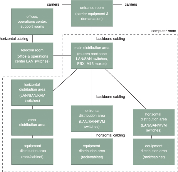
Figure D.1 A data center’s internetworking regions, divided into backbone and horizontal cablings (adapted from TIA-942).
Environmental control subsystems include fire suppression, humidification/dehumidification, and heating, ventilation, and air conditioning (HVAC). Figure D.2 depicts three rack cabinets that are placed so as to enable cold/hot air circulation that optimally utilizes the HVAC subsystems. Controlling this airflow is crucial in order to handle the significant amounts of heat generated by the server racks.
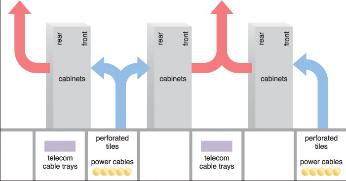
Figure D.2 A depiction of the flow of cold and hot air that accommodates server racks in a typical data center design. The hot air generally leaves the room through ceiling air ducts (adapted from TIA-942).
The power supply system is a complex electrical engineering installation encompassing several subsystems that include:
Utility power infrastructure interconnects with external power utility providers, and is usually supplied by high-voltage power lines in larger data centers. Voltage conversion requires the use of on-site utility power stations, while redundant interconnections are required for electrical grid configurations.
An electrical subsystem that traditionally uses low-voltage alternating current (AC) for its operations, the power distribution system comprises power distribution units that provide electrical power to all data center equipment. The power supplies that are embedded in the computer equipment can require an AC/DC conversion, since some electronic circuits in IT equipment run on DC power. The common inefficiencies of both voltage and AC/DC conversions are notorious for causing power outages.
Many IT resources, most notably physical servers, undergo data loss and other types of malfunctioning if they are unexpectedly shut off. This subsystem is comprised of equipment dedicated to powering the data center during temporary primary power source failures. Multiple UPS devices can operate alongside other power sources to quickly fulfill the data center’s power requirements. The UPS subsystems are also responsible for removing voltage flow fluctuations in order to normalize the incoming current and prevent undue strain on the IT infrastructure. UPS equipment usually relies on DC battery banks, which provide only a few hours’ worth of backup power.
Gas generators are standard combustion engines that are used by larger data centers to sustain operations during natural disasters and power-grid failures. Energy efficiency is commonly measured by the power usage effectiveness (PUE) metric, which is expressed as the ratio of the total facility power entering a data center to the power used by its IT equipment, as follows:

The PUE is determined by the power required by the IT equipment’s supporting subsystems and should ideally be a ratio of 1.0. An average data center would have a PUE over 2.0, while the PUE of a more complex and efficient data center would be closer to 1.2.
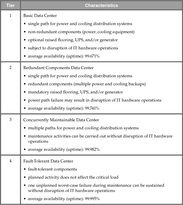
The TIA-942 classification specifies the minimum requirements for infrastructure redundancy in four tiers, an approach that is useful for comparing and evaluating data center facilities (briefly described in Table D.1).