5.1 Broadband Networks and Internet Architecture
Modern-day clouds are underpinned by a set of primary technology components that collectively enable key features and characteristics associated with contemporary cloud computing. The following such technologies are covered in this section:
• Broadband Networks and Internet Architecture
Each existed and matured prior to the advent of cloud computing, although cloud computing advancements helped further evolve select areas of these cloud-enabling technologies.
All clouds must be connected to a network. This inevitable requirement forms an inherent dependency on internetworking.
Internetworks, or the Internet, allow for the remote provisioning of IT resources and are directly supportive of ubiquitous network access. Cloud consumers have the option of accessing the cloud using only private and dedicated network links in LANs, although most clouds are Internet-enabled. The potential of cloud platforms therefore generally grows in parallel with advancements in Internet connectivity and service quality.
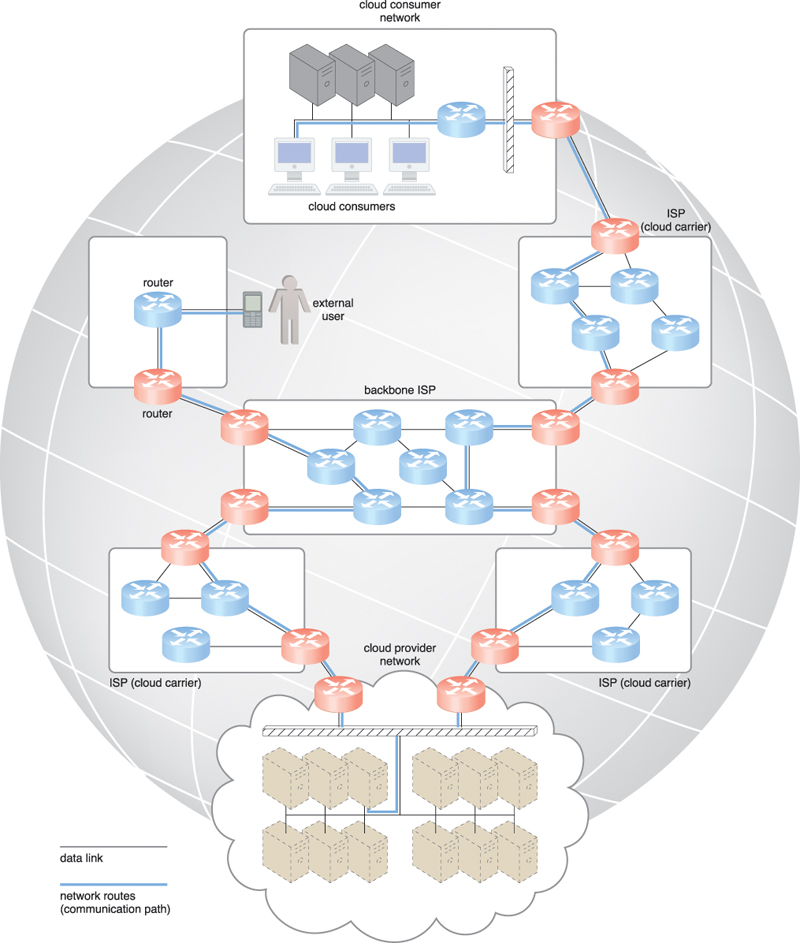
Established and deployed by ISPs, the Internet’s largest backbone networks are strategically interconnected by core routers that connect the world’s multinational networks. As shown in Figure 5.1, an ISP network interconnects to other ISP networks and various organizations.
The concept of the Internet was based on a decentralized provisioning and management model. ISPs can freely deploy, operate, and manage their networks in addition to selecting partner ISPs for interconnection. No centralized entity comprehensively governs the Internet, although bodies like the Internet Corporation for Assigned Names and Numbers (ICANN) supervise and coordinate Internet communications.
Governmental and regulatory laws dictate the service provisioning conditions for organizations and ISPs both within and outside of national borders. Certain realms of the Internet still require the demarcation of national jurisdiction and legal boundaries.
The Internet’s topology has become a dynamic and complex aggregate of ISPs that are highly interconnected via its core protocols. Smaller branches extend from these major nodes of interconnection, branching outwards through smaller networks until eventually reaching every Internet-enabled electronic device.
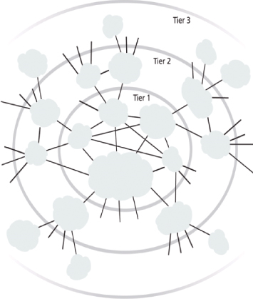
Worldwide connectivity is enabled through a hierarchical topology composed of Tiers 1, 2, and 3 (Figure 5.2). The core Tier 1 is made of large-scale, international cloud providers that oversee massive interconnected global networks, which are connected to Tier 2’s large regional providers. The interconnected ISPs of Tier 2 connect with Tier 1 providers, as well as the local ISPs of Tier 3. Cloud consumers and cloud providers can connect directly using a Tier 1 provider, since any operational ISP can enable Internet connection.
The communication links and routers of the Internet and ISP networks are IT resources that are distributed among countless traffic generation paths. Two fundamental components used to construct the internetworking architecture are connectionless packet switching (datagram networks) and router-based interconnectivity.
End-to-end (sender-receiver pair) data flows are divided into packets of a limited size that are received and processed through network switches and routers, then queued and forwarded from one intermediary node to the next. Each packet carries the necessary location information, such as the Internet Protocol (IP) or Media Access Control (MAC) address, to be processed and routed at every source, intermediary, and destination node.
A router is a device that is connected to multiple networks through which it forwards packets. Even when successive packets are part of the same data flow, routers process and forward each packet individually while maintaining the network topology information that locates the next node on the communication path between the source and destination nodes. Routers manage network traffic and gauge the most efficient hop for packet delivery, since they are privy to both the packet source and packet destination.
The basic mechanics of internetworking are illustrated in Figure 5.3, in which a message is coalesced from an incoming group of disordered packets. The depicted router receives and forwards packets from multiple data flows.
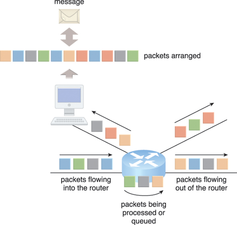
Figure 5.3 Packets traveling through the Internet are directed by a router that arranges them into a message.
The communication path that connects a cloud consumer with its cloud provider may involve multiple ISP networks. The Internet’s mesh structure connects Internet hosts (endpoint systems) using multiple alternative network routes that are determined at runtime. Communication can therefore be sustained even during simultaneous network failures, although using multiple network paths can cause routing fluctuations and latency.
This applies to ISPs that implement the Internet’s internetworking layer and interact with other network technologies, as follows:
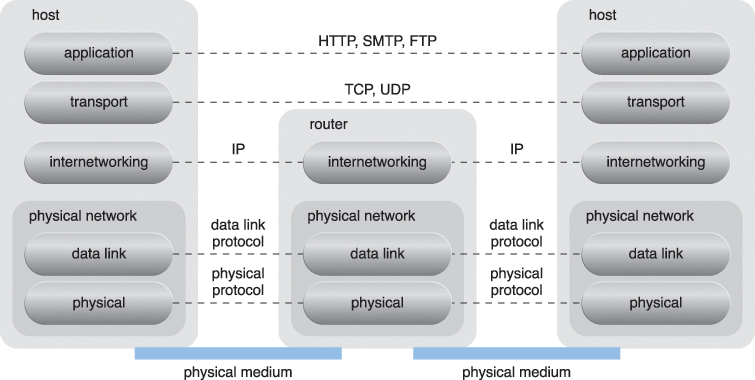
IP packets are transmitted through underlying physical networks that connect adjacent nodes, such as Ethernet, ATM network, and the 3G mobile HSDPA. Physical networks comprise a data link layer that controls data transfer between neighboring nodes, and a physical layer that transmits data bits through both wired and wireless media.
Transport layer protocols, such as the Transmission Control Protocol (TCP) and User Datagram Protocol (UDP), use the IP to provide standardized, end-to-end communication support that facilitates the navigation of data packets across the Internet.
Protocols such as HTTP, SMTP for e-mail, BitTorrent for P2P, and SIP for IP telephony use transport layer protocols to standardize and enable specific data packet transferring methods over the Internet. Many other protocols also fulfill application-centric requirements and use either TCP/IP or UDP as their primary method of data transferring across the Internet and LANs.
Figure 5.4 presents the Internet Reference Model and the protocol stack.
In traditional, on-premise deployment models, enterprise applications and various IT solutions are commonly hosted on centralized servers and storage devices residing in the organization’s own data center. End-user devices, such as smartphones and laptops, access the data center through the corporate network, which provides uninterrupted Internet connectivity.
TCP/IP facilitates both Internet access and on-premise data exchange over LANs (Figure 5.5). Although not commonly referred to as a cloud model, this configuration has been implemented numerous times for medium and large on-premise networks.
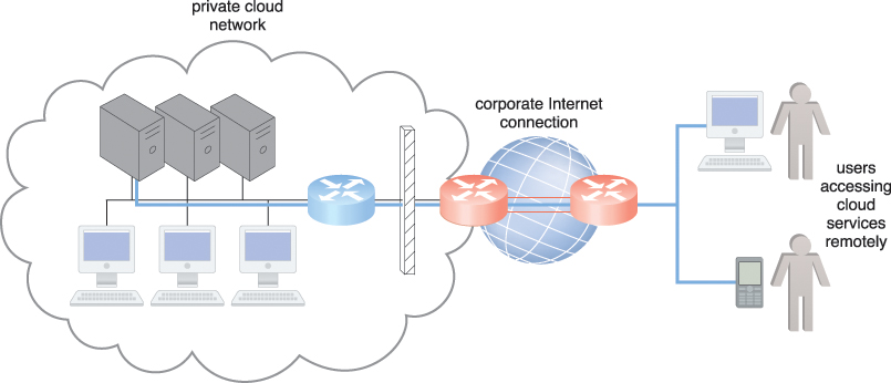
Figure 5.5 The internetworking architecture of a private cloud. The physical IT resources that constitute the cloud are located and managed within the organization.
Organizations using this deployment model can directly access the network traffic to and from the Internet and usually have complete control over and can safeguard their corporate networks using firewalls and monitoring software. These organizations also assume the responsibility of deploying, operating, and maintaining their IT resources and Internet connectivity.
End-user devices that are connected to the network through the Internet can be granted continuous access to centralized servers and applications in the cloud (Figure 5.6).
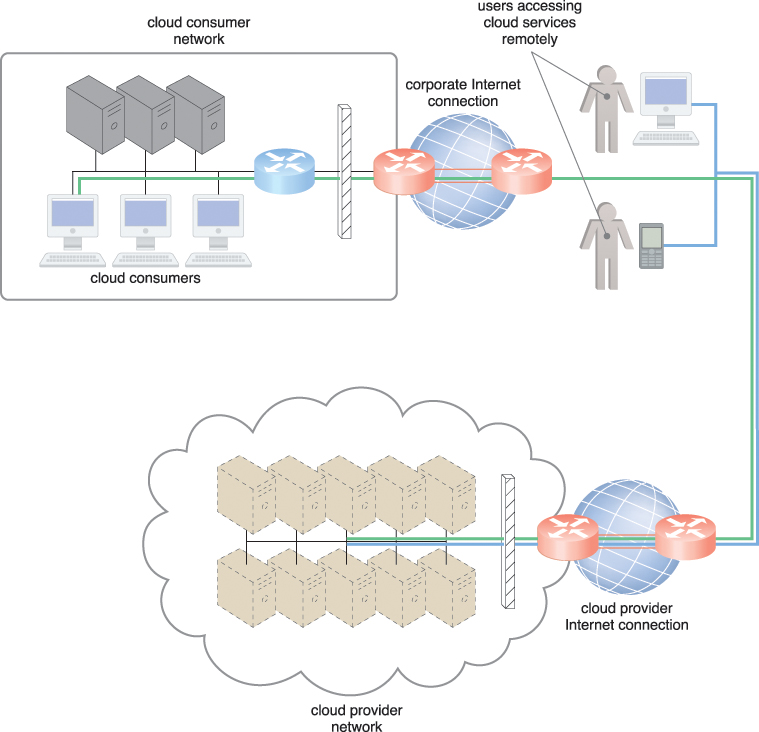
Figure 5.6 The internetworking architecture of an Internet-based cloud deployment model. The Internet is the connecting agent between non-proximate cloud consumers, roaming end-users, and the cloud provider’s own network.
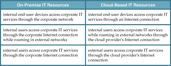
A salient cloud feature that applies to end-user functionality is how centralized IT resources can be accessed using the same network protocols regardless of whether they reside inside or outside of a corporate network. Whether IT resources are on-premise or Internet-based dictates how internal versus external end-users access services, even if the end-users themselves are not concerned with the physical location of cloud-based IT resources (Table 5.1).
Cloud providers can easily configure cloud-based IT resources to be accessible for both external and internal users through an Internet connection (as previously shown in Figure 5.6). This internetworking architecture benefits internal users that require ubiquitous access to corporate IT solutions, as well as cloud consumers that need to provide Internet-based services to external users. Major cloud providers offer Internet connectivity that is superior to the connectivity of individual organizations, resulting in additional network usage charges as part of their pricing model.
In addition to being affected by the bandwidth of the data link that connects networks to ISPs, end-to-end bandwidth is determined by the transmission capacity of the shared data links that connect intermediary nodes. ISPs need to use broadband network technology to implement the core network required to guarantee end-to-end connectivity. This type of bandwidth is constantly increasing, as Web acceleration technologies, such as dynamic caching, compression, and pre-fetching, continue to improve end-user connectivity.
Also referred to as time delay, latency is the amount of time it takes a packet to travel from one data node to another. Latency increases with every intermediary node on the data packet’s path. Transmission queues in the network infrastructure can result in heavy load conditions that also increase network latency. Networks are dependent on traffic conditions in shared nodes, making Internet latency highly variable and often unpredictable.
Packet networks with “best effort” quality-of-service (QoS) typically transmit packets on a first-come/first-serve basis. Data flows that use congested network paths suffer service-level degradation in the form of bandwidth reduction, latency increase, or packet loss when traffic is not prioritized.
The nature of packet switching allows data packets to choose routes dynamically as they travel through the Internet’s network infrastructure. End-to-end QoS can be impacted as a result of this dynamic selecting, since the travel speed of data packets is susceptible to conditions like network congestion and is therefore non-uniform.
IT solutions need to be assessed against business requirements that are affected by network bandwidth and latency, which are inherent to cloud interconnection. Bandwidth is critical for applications that require substantial amounts of data to be transferred to and from the cloud, while latency is critical for applications with a business requirement of swift response times.
The service levels of Internet connections between cloud consumers and cloud providers are determined by their ISPs, which are usually different and therefore include multiple ISP networks in their paths. QoS management across multiple ISPs is difficult to achieve in practice, requiring collaboration of the cloud carriers on both sides to ensure that their end-to-end service levels are sufficient for business requirements.
Cloud consumers and cloud providers may need to use multiple cloud carriers in order to achieve the necessary level of connectivity and reliability for their cloud applications, resulting in additional costs. Cloud adoption can therefore be easier for applications with more relaxed latency and bandwidth requirements.
Grouping IT resources in close proximity with one another, rather than having them geographically dispersed, allows for power sharing, higher efficiency in shared IT resource usage, and improved accessibility for IT personnel. These are the advantages that naturally popularized the data center concept. Modern data centers exist as specialized IT infrastructure used to house centralized IT resources, such as servers, databases, networking and telecommunication devices, and software systems.
Data centers are typically comprised of the following technologies and components:
Data centers consist of both physical and virtualized IT resources. The physical IT resource layer refers to the facility infrastructure that houses computing/networking systems and equipment, together with hardware systems and their operating systems (Figure 5.7). The resource abstraction and control of the virtualization layer is comprised of operational and management tools that are often based on virtualization platforms that abstract the physical computing and networking IT resources as virtualized components that are easier to allocate, operate, release, monitor, and control.
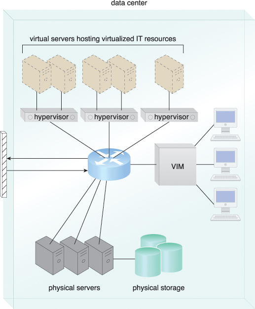
Figure 5.7 The common components of a data center working together to provide virtualized IT resources supported by physical IT resources.
Virtualization components are discussed separately in the upcoming Virtualization Technology section.
Data centers are built upon standardized commodity hardware and designed with modular architectures, aggregating multiple identical building blocks of facility infrastructure and equipment to support scalability, growth, and speedy hardware replacements. Modularity and standardization are key requirements for reducing investment and operational costs as they enable economies of scale for the procurement, acquisition, deployment, operation, and maintenance processes.
Common virtualization strategies and the constantly improving capacity and performance of physical devices both favor IT resource consolidation, since fewer physical components are needed to support complex configurations. Consolidated IT resources can serve different systems and be shared among different cloud consumers.
Data centers have specialized platforms that automate tasks like provisioning, configuration, patching, and monitoring without supervision. Advances in data center management platforms and tools leverage autonomic computing technologies to enable self-configuration and self-recovery. Autonomic computing is briefly discussed in Appendix H: Emerging Technologies (available online only at www.servicetechbooks.com/cloud).
Most of the operational and administrative tasks of IT resources in data centers are commanded through the network’s remote consoles and management systems. Technical personnel are not required to visit the dedicated rooms that house servers, except to perform highly specific tasks, such as equipment handling and cabling or hardware-level installation and maintenance.
Since any form of data center outage significantly impacts business continuity for the organizations that use their services, data centers are designed to operate with increasingly higher levels of redundancy to sustain availability. Data centers usually have redundant, uninterruptable power supplies, cabling, and environmental control subsystems in anticipation of system failure, along with communication links and clustered hardware for load balancing.
Requirements for security, such as physical and logical access controls and data recovery strategies, need to be thorough and comprehensive for data centers, since they are centralized structures that store and process business data.
Due to the sometimes prohibitive nature of building and operating on-premise data centers, outsourcing data center-based IT resources has been a common industry practice for decades. However, the outsourcing models often required long-term consumer commitment and usually could not provide elasticity, issues that a typical cloud can address via inherent features, such as ubiquitous access, on-demand provisioning, rapid elasticity, and pay-per-use.
Data center facilities are custom-designed locations that are outfitted with specialized computing, storage, and network equipment. These facilities have several functional layout areas, as well as various power supplies, cabling, and environmental control stations that regulate heating, ventilation, air conditioning, fire protection, and other related subsystems.
The site and layout of a given data center facility are typically demarcated into segregated spaces. Appendix D provides a breakdown of the common rooms and utilities found in data centers.
Much of the heavy processing in data centers is often executed by standardized commodity servers that have substantial computing power and storage capacity. Several computing hardware technologies are integrated into these modular servers, such as:
• rackmount form factor server design composed of standardized racks with interconnects for power, network, and internal cooling
• support for different hardware processing architectures, such as x86-32bits, x86-64, and RISC
• a power-efficient multi-core CPU architecture that houses hundreds of processing cores in a space as small as a single unit of standardized racks
• redundant and hot-swappable components, such as hard disks, power supplies, network interfaces, and storage controller cards
Computing architectures such as blade server technologies use rack-embedded physical interconnections (blade enclosures), fabrics (switches), and shared power supply units and cooling fans. The interconnections enhance inter-component networking and management while optimizing physical space and power. These systems typically support individual server hot-swapping, scaling, replacement, and maintenance, which benefits the deployment of fault-tolerant systems that are based on computer clusters.
Contemporary computing hardware platforms generally support industry-standard and proprietary operational and management software systems that configure, monitor, and control hardware IT resources from remote management consoles. With a properly established management console, a single operator can oversee hundreds to thousands of physical servers, virtual servers, and other IT resources.
Data centers have specialized storage systems that maintain enormous amounts of digital information in order to fulfill considerable storage capacity needs. These storage systems are containers housing numerous hard disks that are organized into arrays.
Storage systems usually involve the following technologies:
• Hard Disk Arrays – These arrays inherently divide and replicate data among multiple physical drives, and increase performance and redundancy by including spare disks. This technology is often implemented using redundant arrays of independent disks (RAID) schemes, which are typically realized through hardware disk array controllers.
• I/O Caching – This is generally performed through hard disk array controllers, which enhance disk access times and performance by data caching.
• Hot-Swappable Hard Disks – These can be safely removed from arrays without requiring prior powering down.
• Storage Virtualization – This is realized through the use of virtualized hard disks and storage sharing.
• Fast Data Replication Mechanisms – These include snapshotting, which is saving a virtual machine’s memory into a hypervisor-readable file for future reloading, and volume cloning, which is copying virtual or physical hard disk volumes and partitions.
Storage systems encompass tertiary redundancies, such as robotized tape libraries, which are used as backup and recovery systems that typically rely on removable media. This type of system can exist as a networked IT resource or direct-attached storage (DAS), in which a storage system is directly connected to the computing IT resource using a host bus adapter (HBA). In the former case, the storage system is connected to one or more IT resources through a network.
Networked storage devices usually fall into one of the following categories:
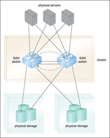
• Storage Area Network (SAN) – Physical data storage media are connected through a dedicated network and provide block-level data storage access using industry standard protocols, such as the Small Computer System Interface (SCSI).
• Network-Attached Storage (NAS) – Hard drive arrays are contained and managed by this dedicated device, which connects through a network and facilitates access to data using file-centric data access protocols like the Network File System (NFS) or Server Message Block (SMB).
NAS, SAN, and other more advanced storage system options provide fault tolerance in many components through controller redundancy, cooling redundancy, and hard disk arrays that use RAID storage technology.
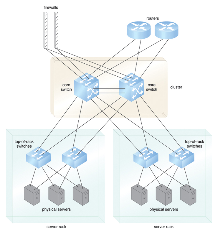
Data centers require extensive network hardware in order to enable multiple levels of connectivity. For a simplified version of networking infrastructure, the data center is broken down into five network subsystems, followed by a summary of the most common elements used for their implementation.
A subsystem related to the internetworking infrastructure, this interconnection is usually comprised of backbone routers that provide routing between external WAN connections and the data center’s LAN, as well as perimeter network security devices such as firewalls and VPN gateways.
This subsystem comprises Web acceleration devices, such as XML pre-processors, encryption/decryption appliances, and layer 7 switching devices that perform content-aware routing.
The LAN fabric constitutes the internal LAN and provides high-performance and redundant connectivity for all of the data center’s network-enabled IT resources. It is often implemented with multiple network switches that facilitate network communications and operate at speeds of up to ten gigabits per second. These advanced network switches can also perform several virtualization functions, such as LAN segregation into VLANs, link aggregation, controlled routing between networks, load balancing, and failover.
Related to the implementation of storage area networks (SANs) that provide connectivity between servers and storage systems, the SAN fabric is usually implemented with Fibre Channel (FC), Fibre Channel over Ethernet (FCoE), and InfiniBand network switches.
This subsystem supplies attachment points for NAS-based storage devices and implements protocol conversion hardware that facilitates data transmission between SAN and NAS devices.
Data center network technologies have operational requirements for scalability and high availability that are fulfilled by employing redundant and/or fault-tolerant configurations. These five network subsystems improve data center redundancy and reliability to ensure that they have enough IT resources to maintain a certain level of service even in the face of multiple failures.
Ultra high-speed network optical links can be used to aggregate individual gigabit-per-second channels into single optical fibers using multiplexing technologies like dense wavelength-division multiplexing (DWDM). Spread over multiple locations and used to interconnect server farms, storage systems, and replicated data centers, optical links improve transfer speeds and resiliency.
IT hardware is subject to rapid technological obsolescence, with lifecycles that typically last between five to seven years. The on-going need to replace equipment frequently results in a mix of hardware whose heterogeneity can complicate the entire data center’s operations and management (although this can be partially mitigated through virtualization).
Security is another major issue when considering the role of the data center and the vast quantities of data contained within its doors. Even with extensive security precautions in place, housing data exclusively at one data center facility means much more can be compromised by a successful security incursion than if data was distributed across individual unlinked components.
Virtualization is the process of converting a physical IT resource into a virtual IT resource.
Most types of IT resources can be virtualized, including:
• Servers – A physical server can be abstracted into a virtual server.
• Storage – A physical storage device can be abstracted into a virtual storage device or a virtual disk.
• Network – Physical routers and switches can be abstracted into logical network fabrics, such as VLANs.
• Power – A physical UPS and power distribution units can be abstracted into what are commonly referred to as virtual UPSs.
This section focuses on the creation and deployment of virtual servers through server virtualization technology.
Note
The terms virtual server and virtual machine (VM) are used synonymously throughout this book.
The first step in creating a new virtual server through virtualization software is the allocation of physical IT resources, followed by the installation of an operating system. Virtual servers use their own guest operating systems, which are independent of the operating system in which they were created.
Both the guest operating system and the application software running on the virtual server are unaware of the virtualization process, meaning these virtualized IT resources are installed and executed as if they were running on a separate physical server. This uniformity of execution that allows programs to run on physical systems as they would on virtual systems is a vital characteristic of virtualization. Guest operating systems typically require seamless usage of software products and applications that do not need to be customized, configured, or patched in order to run in a virtualized environment.
Virtualization software runs on a physical server called a host or physical host, whose underlying hardware is made accessible by the virtualization software. The virtualization software functionality encompasses system services that are specifically related to virtual machine management and not normally found on standard operating systems. This is why this software is sometimes referred to as a virtual machine manager or a virtual machine monitor (VMM), but most commonly known as a hypervisor. (The hypervisor is formally described as a cloud computing mechanism in Chapter 8.)
The installation of an operating system’s configuration and application software in a unique IT hardware platform results in many software-hardware dependencies. In a non-virtualized environment, the operating system is configured for specific hardware models and requires reconfiguration if these IT resources need to be modified.
Virtualization is a conversion process that translates unique IT hardware into emulated and standardized software-based copies. Through hardware independence, virtual servers can easily be moved to another virtualization host, automatically resolving multiple hardware-software incompatibility issues. As a result, cloning and manipulating virtual IT resources is much easier than duplicating physical hardware. The architectural models explored in Part III of this book provide numerous examples of this.
The coordination function that is provided by the virtualization software allows multiple virtual servers to be simultaneously created in the same virtualization host. Virtualization technology enables different virtual servers to share one physical server. This process is called server consolidation and is commonly used to increase hardware utilization, load balancing, and optimization of available IT resources. The resulting flexibility is such that different virtual servers can run different guest operating systems on the same host.
This fundamental capability directly supports common cloud features, such as on-demand usage, resource pooling, elasticity, scalability, and resiliency.
Virtual servers are created as virtual disk images that contain binary file copies of hard disk content. These virtual disk images are accessible to the host’s operating system, meaning simple file operations, such as copy, move, and paste, can be used to replicate, migrate, and back up the virtual server. This ease of manipulation and replication is one of the most salient features of virtualization technology as it enables:
• The creation of standardized virtual machine images commonly configured to include virtual hardware capabilities, guest operating systems, and additional application software, for pre-packaging in virtual disk images in support of instantaneous deployment.
• Increased agility in the migration and deployment of a virtual machine’s new instances by being able to rapidly scale out and up.
• The ability to roll back, which is the instantaneous creation of VM snapshots by saving the state of the virtual server’s memory and hard disk image to a host-based file. (Operators can easily revert to these snapshots and restore the virtual machine to its prior state.)
• The support of business continuity with efficient backup and restoration procedures, as well as the creation of multiple instances of critical IT resources and applications.
Operating system-based virtualization is the installation of virtualization software in a pre-existing operating system, which is called the host operating system (Figure 5.8). For example, a user whose workstation is installed with a specific version of Windows wants to generate virtual servers and installs virtualization software into the host operating system like any other program. This user needs to use this application to generate and operate one or more virtual servers. The user needs to use virtualization software to enable direct access to any of the generated virtual servers. Since the host operating system can provide hardware devices with the necessary support, operating system virtualization can rectify hardware compatibility issues even if the hardware driver is not available to the virtualization software.
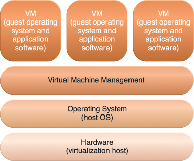
Figure 5.8 The different logical layers of operating system-based virtualization, in which the VM is first installed into a full host operating system and subsequently used to generate virtual machines.
Hardware independence that is enabled by virtualization allows hardware IT resources to be more flexibly used. For example, consider a scenario in which the host operating system has the software necessary for controlling five network adapters that are available to the physical computer. The virtualization software can make the five network adapters available to the virtual server, even if the virtualized operating system is incapable of physically housing five network adapters.
Virtualization software translates hardware IT resources that require unique software for operation into virtualized IT resources that are compatible with a range of operating systems. Since the host operating system is a complete operating system in itself, many operating system-based services that are available as administration tools can be used to manage the physical host.
Examples of such services include:
• Backup and Recovery
• Integration to Directory Services
• Security Management
Operating system-based virtualization can introduce demands and issues related to performance overhead such as:
• The host operating system consumes CPU, memory, and other hardware IT resources.
• Hardware-related calls from guest operating systems need to traverse several layers to and from the hardware, which decreases overall performance.
• Licenses are usually required for host operating systems, in addition to individual licenses for each of their guest operating systems.
A concern with operating system-based virtualization is the processing overhead required to run the virtualization software and host operating systems. Implementing a virtualization layer will negatively affect overall system performance. Estimating, monitoring, and managing the resulting impact can be challenging because it requires expertise in system workloads, software and hardware environments, and sophisticated monitoring tools.
This option represents the installation of virtualization software directly on the physical host hardware so as to bypass the host operating system, which is presumably engaged with operating system-based virtualization (Figure 5.9). Allowing the virtual servers to interact with hardware without requiring intermediary action from the host operating system generally makes hardware-based virtualization more efficient.
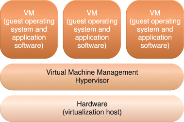
Figure 5.9 The different logical layers of hardware-based virtualization, which does not require another host operating system.
Virtualization software is typically referred to as a hypervisor for this type of processing. A hypervisor has a simple user-interface that requires a negligible amount of storage space. It exists as a thin layer of software that handles hardware management functions to establish a virtualization management layer. Device drivers and system services are optimized for the provisioning of virtual servers, although many standard operating system functions are not implemented. This type of virtualization system is essentially used to optimize performance overhead inherent to the coordination that enables multiple virtual servers to interact with the same hardware platform.
One of the main issues of hardware-based virtualization concerns compatibility with hardware devices. The virtualization layer is designed to communicate directly with the host hardware, meaning all of the associated device drivers and support software need to be compatible with the hypervisor. Hardware device drivers may not be as available to hypervisor platforms as they are to operating systems. Host management and administration features may further not include the range of advanced functions that are common to operating systems.
Many administrative tasks can be performed more easily using virtual servers as opposed to using their physical counterparts. Modern virtualization software provides several advanced management functions that can automate administration tasks and reduce the overall operational burden on virtualized IT resources.
Virtualized IT resource management is often supported by virtualization infrastructure management (VIM) tools that collectively manage virtual IT resources and rely on a centralized management module, otherwise known as a controller, that runs on a dedicated computer. VIMs are commonly encompassed by the resource management system mechanism described in Chapter 9.
• Performance Overhead – Virtualization may not be ideal for complex systems that have high workloads with little use for resource sharing and replication. A poorly formulated virtualization plan can result in excessive performance overhead. A common strategy used to rectify the overhead issue is a technique called para-virtualization, which presents a software interface to the virtual machines that is not identical to that of the underlying hardware. The software interface has instead been modified to reduce the guest operating system’s processing overhead, which is more difficult to manage. A major drawback of this approach is the need to adapt the guest operating system to the para-virtualization API, which can impair the use of standard guest operating systems while decreasing solution portability.
• Special Hardware Compatibility – Many hardware vendors that distribute specialized hardware may not have device driver versions that are compatible with virtualization software. Conversely, the software itself may be incompatible with recently released hardware versions. These types of incompatibility issues can be resolved using established commodity hardware platforms and mature virtualization software products.
• Portability – The programmatic and management interfaces that establish administration environments for a virtualization program to operate with various virtualization solutions can introduce portability gaps due to incompatibilities. Initiatives such as the Open Virtualization Format (OVF) for the standardization of virtual disk image formats are dedicated to alleviating this concern.
Due to cloud computing’s fundamental reliance on internetworking, Web browser universality, and the ease of Web-based service development, Web technology is generally used as both the implementation medium and the management interface for cloud services.
This section introduces the primary Web technologies and discusses their relationship to cloud services.
The World Wide Web is a system of interlinked IT resources that are accessed through the Internet. The two basic components of the Web are the Web browser client and the Web server. Other components, such as proxies, caching services, gateways, and load balancers, are used to improve Web application characteristics such as scalability and security. These additional components reside in a layered architecture that is positioned between the client and the server.
Three fundamental elements comprise the technology architecture of the Web:
• Uniform Resource Locator (URL) – A standard syntax used for creating identifiers that point to Web-based resources, the URL is often structured using a logical network location.
• Hypertext Transfer Protocol (HTTP) – This is the primary communications protocol used to exchange content and data throughout the World Wide Web. URLs are typically transmitted via HTTP.
• Markup Languages (HTML, XML) – Markup languages provide a lightweight means of expressing Web-centric data and metadata. The two primary markup languages are HTML (which is used to express the presentation of Web pages) and XML (which allows for the definition of vocabularies used to associate meaning to Web-based data via metadata).
For example, a Web browser can request to execute an action like read, write, update, or delete on a Web resource on the Internet, and proceed to identify and locate the Web resource through its URL. The request is sent using HTTP to the resource host, which is also identified by a URL. The Web server locates the Web resource and performs the requested operation, which is followed by a response being sent back to the client. The response may be comprised of content that includes HTML and XML statements.
Web resources are represented as hypermedia as opposed to hypertext, meaning media such as graphics, audio, video, plain text, and URLs can be referenced collectively in a single document. Some types of hypermedia resources cannot be rendered without additional software or Web browser plug-ins.
A distributed application that uses Web-based technologies (and generally relies on Web browsers for the presentation of user-interfaces) is typically considered a Web application. These applications can be found in all kinds of cloud-based environments due to their high accessibility.
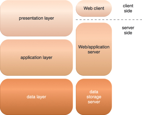
Figure 5.10 presents a common architectural abstraction for Web applications that is based on the basic three-tier model. The first tier is called the presentation layer, which represents the user-interface. The middle tier is the application layer that implements application logic, while the third tier is the data layer that is comprised of persistent data stores.
The presentation layer has components on both the client and server-side. Web servers receive client requests and retrieve requested resources directly as static Web content and indirectly as dynamic Web content, which is generated according to the application logic. Web servers interact with application servers in order to execute the requested application logic, which then typically involves interaction with one or more underlying databases.
PaaS ready-made environments enable cloud consumers to develop and deploy Web applications. Typical PaaS offerings have separate instances of the Web server, application server, and data storage server environments.
The multitenant application design was created to enable multiple users (tenants) to access the same application logic simultaneously. Each tenant has its own view of the application that it uses, administers, and customizes as a dedicated instance of the software while remaining unaware of other tenants that are using the same application.
Multitenant applications ensure that tenants do not have access to data and configuration information that is not their own. Tenants can individually customize features of the application, such as:
• User Interface – Tenants can define a specialized “look and feel” for their application interface.
• Business Process – Tenants can customize the rules, logic, and workflows of the business processes that are implemented in the application.
• Data Model – Tenants can extend the data schema of the application to include, exclude, or rename fields in the application data structures.
• Access Control – Tenants can independently control the access rights for users and groups.
Multitenant application architecture is often significantly more complex than that of single-tenant applications. Multitenant applications need to support the sharing of various artifacts by multiple users (including portals, data schemas, middleware, and databases), while maintaining security levels that segregate individual tenant operational environments.
Common characteristics of multitenant applications include:
• Usage Isolation – The usage behavior of one tenant does not affect the application availability and performance of other tenants.
• Data Security – Tenants cannot access data that belongs to other tenants.
• Recovery – Backup and restore procedures are separately executed for the data of each tenant.
• Application Upgrades – Tenants are not negatively affected by the synchronous upgrading of shared software artifacts.
• Scalability – The application can scale to accommodate increases in usage by existing tenants and/or increases in the number of tenants.
• Metered Usage – Tenants are charged only for the application processing and features that are actually consumed.
• Data Tier Isolation – Tenants can have individual databases, tables, and/or schemas isolated from other tenants. Alternatively, databases, tables, and/or schemas can be designed to be intentionally shared by tenants.
A multitenant application that is being concurrently used by two different tenants is illustrated in Figure 5.11. This type of application is typical with SaaS implementations.
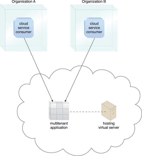
Figure 5.11 A multitenant application that is serving multiple cloud service consumers simultaneously.
The field of service technology is a keystone foundation of cloud computing that formed the basis of the “as-a-service” cloud delivery models. Several prominent service technologies that are used to realize and build upon cloud-based environments are described in this section.
Also commonly prefixed with “SOAP-based,” Web services represent an established and common medium for sophisticated, Web-based service logic. Along with XML, the core technologies behind Web services are represented by the following industry standards:
• Web Service Description Language (WSDL) – This markup language is used to create a WSDL definition that defines the application programming interface (API) of a Web service, including its individual operations (functions) and each operation’s input and output messages.
• XML Schema Definition Language (XML Schema) – Messages exchanged by Web services must be expressed using XML. XML schemas are created to define the data structure of the XML-based input and output messages exchanged by Web services. XML schemas can be directly linked to or embedded within WSDL definitions.
• SOAP – Formerly known as the Simple Object Access Protocol, this standard defines a common messaging format used for request and response messages exchanged by Web services. SOAP messages are comprised of body and header sections. The former houses the main message content and the latter is used to contain metadata that can be processed at runtime.
• Universal Description, Discovery, and Integration (UDDI) – This standard regulates service registries in which WSDL definitions can be published as part of a service catalog for discovery purposes.
These four technologies collectively form the first generation of Web service technologies (Figure 5.12). A comprehensive set of second-generation Web service technologies (commonly referred to as WS-*) has been developed to address various additional functional areas, such as security, reliability, transactions, routing, and business process automation.
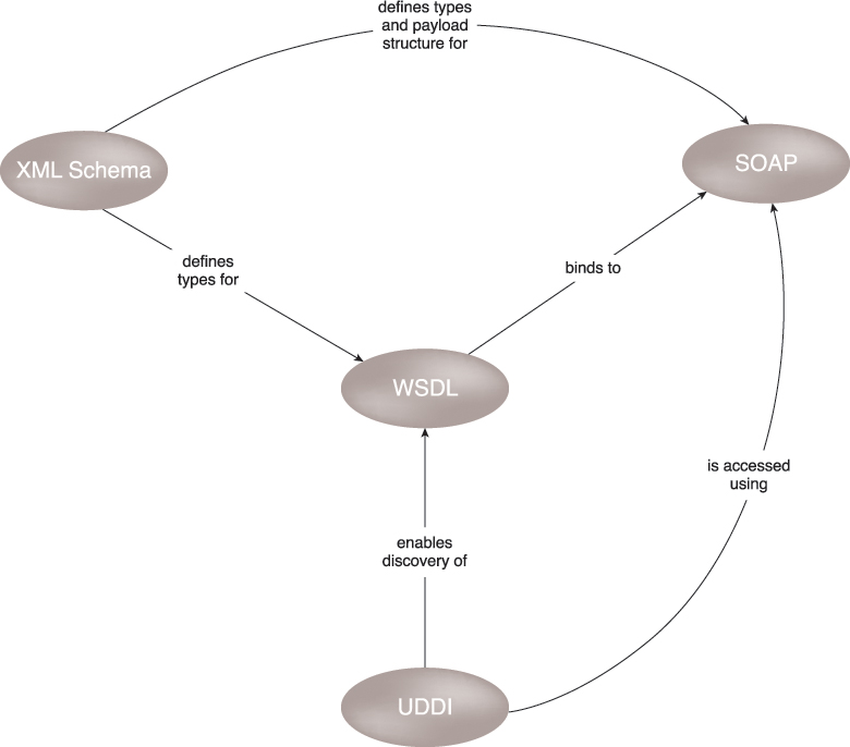
Figure 5.12 An overview of how first-generation Web service technologies commonly relate to each other.
Note
To learn more about Web service technologies, read Web Service Contract Design & Versioning for SOA from the Prentice Hall Service Technology Series from Thomas Erl. This title covers first and second-generation Web service standards in technical detail. See www.servicetechbooks.com/wsc for more information.
REST services are designed according to a set of constraints that shape the service architecture to emulate the properties of the World Wide Web, resulting in service implementations that rely on the use of core Web technologies (described in the Web Technology section).
Unlike Web services, REST services do not have individual technical interfaces but instead share a common technical interface that is known as the uniform contract, which is typically established via the use of HTTP methods.
The six REST design constraints are:
• Client-Server
• Stateless
• Cache
• Interface/Uniform Contract
• Layered System
• Code-On-Demand
Each design constraint is described in detail at www.whatisrest.com.
Note
To learn more about REST services read SOA with REST: Principles, Patterns & Constraints for Building Enterprise Solutions with REST from the Prentice Hall Service Technology Series from Thomas Erl. See www.servicetechbooks.com/rest for details.
Service agents are event-driven programs designed to intercept messages at runtime. There are active and passive service agents, both of which are common in cloud environments. Active service agents perform an action upon intercepting and reading the contents of a message. The action typically requires making changes to the message contents (most commonly message header data and less commonly the body content) or changes to the message path itself. Passive service agents, on the other hand, do not change message contents. Instead, they read the message and may then capture certain parts of its contents, usually for monitoring, logging, or reporting purposes.
Cloud-based environments rely heavily on the use of system-level and custom service agents to perform much of the runtime monitoring and measuring required to ensure that features, such as elastic scaling and pay-for-use billing, can be carried out instantaneously.
Several of the mechanisms described in Part II of this book exist as, or rely on the use of, service agents.
Falling under the umbrella of service technology is the large market of middleware platforms that evolved from messaging-oriented middleware (MOM) platforms used primarily to facilitate integration, to sophisticated service middleware platforms designed to accommodate complex service compositions.
The two most common types of middleware platforms relevant to services computing are the enterprise service bus (ESB) and the orchestration platform. The ESB encompasses a range of intermediary processing features, including service brokerage, routing, and message queuing. Orchestration environments are designed to host and execute workflow logic that drives the runtime composition of services.
Both forms of service middleware can be deployed and operated within cloud-based environments.
• Tier-3 facility infrastructure, which provides redundant configurations for all of the central subsystems in the data center facility layer.
• Redundant connections with utility service providers that have installed local capacity for power generation and water supply that activates in the event of general failure.
• An internetwork that supplies an ultra-high bandwidth interconnection between the three data centers through dedicated links.
• Redundant Internet connections in each data center to multiple ISPs and the .GOV extranet, which interconnects DTGOV with its main government clients.
• Standardized hardware of higher aggregated capacity that is abstracted by a cloud-aware virtualization platform.
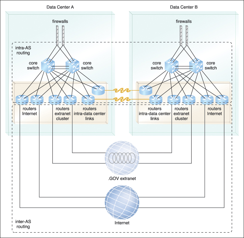
Figure 5.15 The internetworking setup between two data centers that is similarly implemented between every pair of DTGOV data centers. The DTGOV internetwork is designed to be an autonomous system (AS) on the Internet, meaning the links interconnecting the data centers with the LANs define the intra-AS routing domain. The interconnections to external ISPs are controlled through inter-AS routing technology, which shapes Internet traffic and enables flexible configurations for load-balancing and failover.