11.1 Workload Distribution Architecture
11.2 Resource Pooling Architecture
11.3 Dynamic Scalability Architecture
11.4 Elastic Resource Capacity Architecture
11.5 Service Load Balancing Architecture
11.6 Cloud Bursting Architecture
11.7 Elastic Disk Provisioning Architecture
11.8 Redundant Storage Architecture
This chapter introduces and describes several of the more common foundational cloud architectural models, each exemplifying a common usage and characteristic of contemporary cloud-based environments. The involvement and importance of different combinations of cloud computing mechanisms in relation to these architectures are explored.
IT resources can be horizontally scaled via the addition of one or more identical IT resources, and a load balancer that provides runtime logic capable of evenly distributing the workload among the available IT resources (Figure 11.1). The resulting workload distribution architecture reduces both IT resource over-utilization and under-utilization to an extent dependent upon the sophistication of the load balancing algorithms and runtime logic.

Figure 11.1 A redundant copy of Cloud Service A is implemented on Virtual Server B. The load balancer intercepts cloud service consumer requests and directs them to both Virtual Servers A and B to ensure even workload distribution.
This fundamental architectural model can be applied to any IT resource, with workload distribution commonly carried out in support of distributed virtual servers, cloud storage devices, and cloud services. Load balancing systems applied to specific IT resources usually produce specialized variations of this architecture that incorporate aspects of load balancing, such as:
• the service load balancing architecture explained later in this chapter
• the load balanced virtual server architecture covered in Chapter 12
• the load balanced virtual switches architecture described in Chapter 13
In addition to the base load balancer mechanism, and the virtual server and cloud storage device mechanisms to which load balancing can be applied, the following mechanisms can also be part of this cloud architecture:
• Audit Monitor – When distributing runtime workloads, the type and geographical location of the IT resources that process the data can determine whether monitoring is necessary to fulfill legal and regulatory requirements.
• Cloud Usage Monitor – Various monitors can be involved to carry out runtime workload tracking and data processing.
• Hypervisor – Workloads between hypervisors and the virtual servers that they host may require distribution.
• Logical Network Perimeter – The logical network perimeter isolates cloud consumer network boundaries in relation to how and where workloads are distributed.
• Resource Cluster – Clustered IT resources in active/active mode are commonly used to support workload balancing between different cluster nodes.
• Resource Replication – This mechanism can generate new instances of virtualized IT resources in response to runtime workload distribution demands.
A resource pooling architecture is based on the use of one or more resource pools, in which identical IT resources are grouped and maintained by a system that automatically ensures that they remain synchronized.
Provided here are common examples of resource pools:
Physical server pools are composed of networked servers that have been installed with operating systems and other necessary programs and/or applications and are ready for immediate use.
Virtual server pools are usually configured using one of several available templates chosen by the cloud consumer during provisioning. For example, a cloud consumer can set up a pool of mid-tier Windows servers with 4 GB of RAM or a pool of low-tier Ubuntu servers with 2 GB of RAM.
Storage pools, or cloud storage device pools, consist of file-based or block-based storage structures that contain empty and/or filled cloud storage devices.
Network pools (or interconnect pools) are composed of different preconfigured network connectivity devices. For example, a pool of virtual firewall devices or physical network switches can be created for redundant connectivity, load balancing, or link aggregation.
CPU pools are ready to be allocated to virtual servers, and are typically broken down into individual processing cores.
Pools of physical RAM can be used in newly provisioned physical servers or to vertically scale physical servers.
Dedicated pools can be created for each type of IT resource and individual pools can be grouped into a larger pool, in which case each individual pool becomes a sub-pool (Figure 11.2).
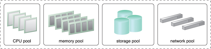
Figure 11.2 A sample resource pool that is comprised of four sub-pools of CPUs, memory, cloud storage devices, and virtual network devices.
Resource pools can become highly complex, with multiple pools created for specific cloud consumers or applications. A hierarchical structure can be established to form parent, sibling, and nested pools in order to facilitate the organization of diverse resource pooling requirements (Figure 11.3).
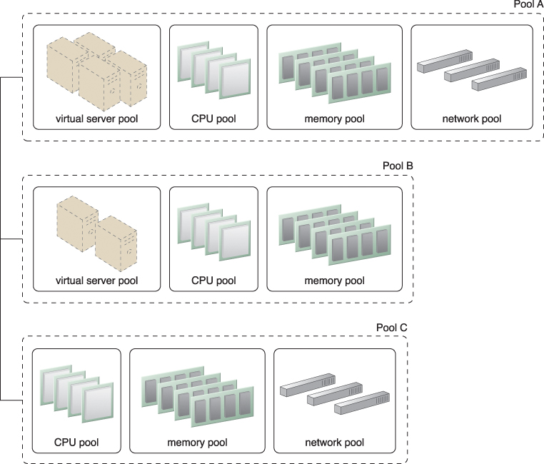
Figure 11.3 Pools B and C are sibling pools that are taken from the larger Pool A, which has been allocated to a cloud consumer. This is an alternative to taking the IT resources for Pool B and Pool C from a general reserve of IT resources that is shared throughout the cloud.
Sibling resource pools are usually drawn from physically grouped IT resources, as opposed to IT resources that are spread out over different data centers. Sibling pools are isolated from one another so that each cloud consumer is only provided access to its respective pool.
In the nested pool model, larger pools are divided into smaller pools that individually group the same type of IT resources together (Figure 11.4). Nested pools can be used to assign resource pools to different departments or groups in the same cloud consumer organization.
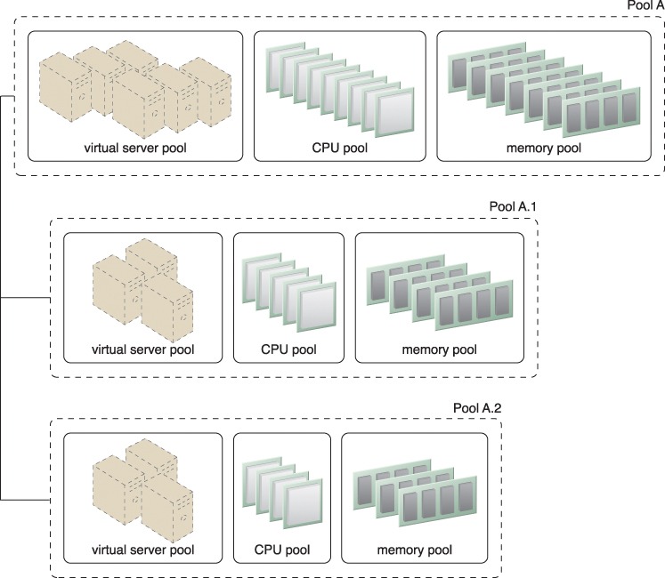
Figure 11.4 Nested Pools A.1 and Pool A.2 are comprised of the same IT resources as Pool A, but in different quantities. Nested pools are typically used to provision cloud services that need to be rapidly instantiated using the same type of IT resources with the same configuration settings.
After resources pools have been defined, multiple instances of IT resources from each pool can be created to provide an in-memory pool of “live” IT resources.
In addition to cloud storage devices and virtual servers, which are commonly pooled mechanisms, the following mechanisms can also be part of this cloud architecture:
• Audit Monitor – This mechanism monitors resource pool usage to ensure compliance with privacy and regulation requirements, especially when pools contain cloud storage devices or data loaded into memory.
• Cloud Usage Monitor – Various cloud usage monitors are involved in the runtime tracking and synchronization that are required by the pooled IT resources and any underlying management systems.
• Hypervisor – The hypervisor mechanism is responsible for providing virtual servers with access to resource pools, in addition to hosting the virtual servers and sometimes the resource pools themselves.
• Logical Network Perimeter – The logical network perimeter is used to logically organize and isolate resource pools.
• Pay-Per-Use Monitor – The pay-per-use monitor collects usage and billing information on how individual cloud consumers are allocated and use IT resources from various pools.
• Remote Administration System – This mechanism is commonly used to interface with backend systems and programs in order to provide resource pool administration features via a front-end portal.
• Resource Management System – The resource management system mechanism supplies cloud consumers with the tools and permission management options for administering resource pools.
• Resource Replication – This mechanism is used to generate new instances of IT resources for resource pools.
The dynamic scalability architecture is an architectural model based on a system of predefined scaling conditions that trigger the dynamic allocation of IT resources from resource pools. Dynamic allocation enables variable utilization as dictated by usage demand fluctuations, since unnecessary IT resources are efficiently reclaimed without requiring manual interaction.
The automated scaling listener is configured with workload thresholds that dictate when new IT resources need to be added to the workload processing. This mechanism can be provided with logic that determines how many additional IT resources can be dynamically provided, based on the terms of a given cloud consumer’s provisioning contract.
The following types of dynamic scaling are commonly used:
• Dynamic Horizontal Scaling – IT resource instances are scaled out and in to handle fluctuating workloads. The automatic scaling listener monitors requests and signals resource replication to initiate IT resource duplication, as per requirements and permissions.
• Dynamic Vertical Scaling – IT resource instances are scaled up and down when there is a need to adjust the processing capacity of a single IT resource. For example, a virtual server that is being overloaded can have its memory dynamically increased or it may have a processing core added.
• Dynamic Relocation – The IT resource is relocated to a host with more capacity. For example, a database may need to be moved from a tape-based SAN storage device with 4 GB per second I/O capacity to another disk-based SAN storage device with 8 GB per second I/O capacity.
Figures 11.5 to 11.7 illustrate the process of dynamic horizontal scaling.
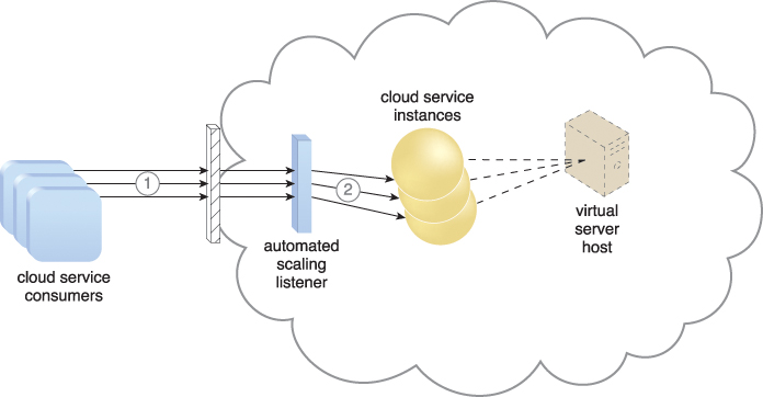
Figure 11.5 Cloud service consumers are sending requests to a cloud service (1). The automated scaling listener monitors the cloud service to determine if predefined capacity thresholds are being exceeded (2).
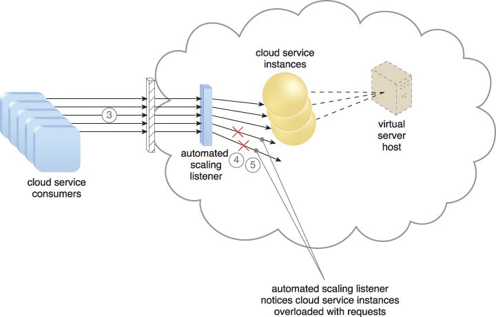
Figure 11.6 The number of requests coming from cloud service consumers increases (3). The workload exceeds the performance thresholds. The automated scaling listener determines the next course of action based on a predefined scaling policy (4). If the cloud service implementation is deemed eligible for additional scaling, the automated scaling listener initiates the scaling process (5).
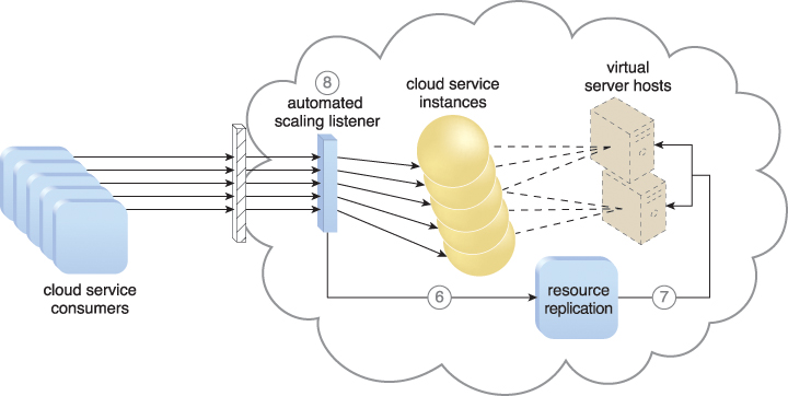
Figure 11.7 The automated scaling listener sends a signal to the resource replication mechanism (6), which creates more instances of the cloud service (7). Now that the increased workload has been accommodated, the automated scaling listener resumes monitoring and detracting and adding IT resources, as required (8).
The dynamic scalability architecture can be applied to a range of IT resources, including virtual servers and cloud storage devices. Besides the core automated scaling listener and resource replication mechanisms, the following mechanisms can also be used in this form of cloud architecture:
• Cloud Usage Monitor – Specialized cloud usage monitors can track runtime usage in response to dynamic fluctuations caused by this architecture.
• Hypervisor – The hypervisor is invoked by a dynamic scalability system to create or remove virtual server instances, or to be scaled itself.
• Pay-Per-Use Monitor – The pay-per-use monitor is engaged to collect usage cost information in response to the scaling of IT resources.
The elastic resource capacity architecture is primarily related to the dynamic provisioning of virtual servers, using a system that allocates and reclaims CPUs and RAM in immediate response to the fluctuating processing requirements of hosted IT resources (Figures 11.8 and 11.9).
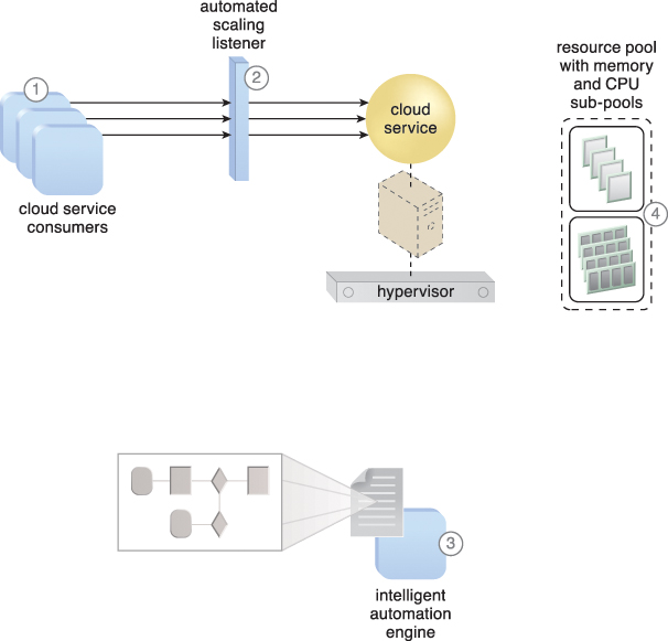
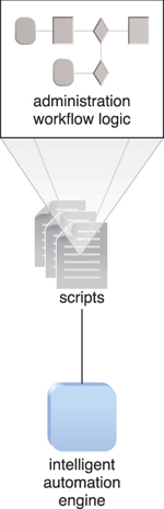
Figure 11.8 Cloud service consumers are actively sending requests to a cloud service (1), which are monitored by an automated scaling listener (2). An intelligent automation engine script is deployed with workflow logic (3) that is capable of notifying the resource pool using allocation requests (4).
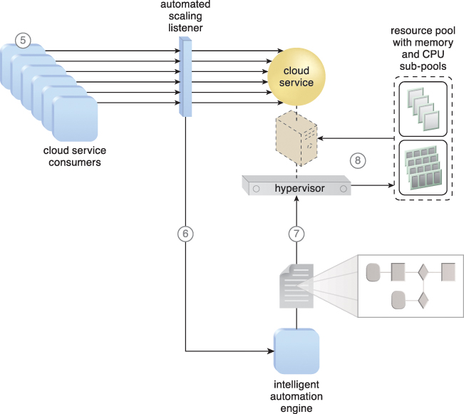
Figure 11.9 Cloud service consumer requests increase (5), causing the automated scaling listener to signal the intelligent automation engine to execute the script (6). The script runs the workflow logic that signals the hypervisor to allocate more IT resources from the resource pools (7). The hypervisor allocates additional CPU and RAM to the virtual server, enabling the increased workload to be handled (8).
Resource pools are used by scaling technology that interacts with the hypervisor and/or VIM to retrieve and return CPU and RAM resources at runtime. The runtime processing of the virtual server is monitored so that additional processing power can be leveraged from the resource pool via dynamic allocation, before capacity thresholds are met. The virtual server and its hosted applications and IT resources are vertically scaled in response.
This type of cloud architecture can be designed so that the intelligent automation engine script sends its scaling request via the VIM instead of to the hypervisor directly. Virtual servers that participate in elastic resource allocation systems may require rebooting in order for the dynamic resource allocation to take effect.
Some additional mechanisms that can be included in this cloud architecture are the following:
• Cloud Usage Monitor – Specialized cloud usage monitors collect resource usage information on IT resources before, during, and after scaling, to help define the future processing capacity thresholds of the virtual servers.
• Pay-Per-Use Monitor – The pay-per-use monitor is responsible for collecting resource usage cost information as it fluctuates with the elastic provisioning.
• Resource Replication – Resource replication is used by this architectural model to generate new instances of the scaled IT resources.
The service load balancing architecture can be considered a specialized variation of the workload distribution architecture that is geared specifically for scaling cloud service implementations. Redundant deployments of cloud services are created, with a load balancing system added to dynamically distribute workloads.
The duplicate cloud service implementations are organized into a resource pool, while the load balancer is positioned as either an external or built-in component to allow the host servers to balance the workloads themselves.
Depending on the anticipated workload and processing capacity of host server environments, multiple instances of each cloud service implementation can be generated as part of a resource pool that responds to fluctuating request volumes more efficiently.
The load balancer can be positioned either independent of the cloud services and their host servers (Figure 11.10), or built-in as part of the application or server’s environment. In the latter case, a primary server with the load balancing logic can communicate with neighboring servers to balance the workload (Figure 11.11).
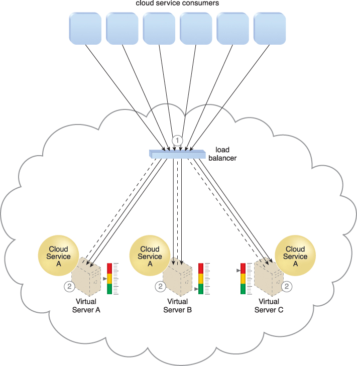
Figure 11.10 The load balancer intercepts messages sent by cloud service consumers (1) and forwards them to the virtual servers so that the workload processing is horizontally scaled (2).
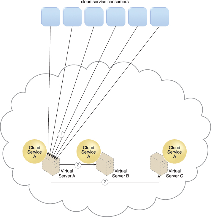
Figure 11.11 Cloud service consumer requests are sent to Cloud Service A on Virtual Server A (1). The cloud service implementation includes built-in load balancing logic that is capable of distributing requests to the neighboring Cloud Service A implementations on Virtual Servers B and C (2).
The service load balancing architecture can involve the following mechanisms in addition to the load balancer:
• Cloud Usage Monitor – Cloud usage monitors may be involved with monitoring cloud service instances and their respective IT resource consumption levels, as well as various runtime monitoring and usage data collection tasks.
• Resource Cluster – Active-active cluster groups are incorporated in this architecture to help balance workloads across different members of the cluster.
• Resource Replication – The resource replication mechanism is utilized to generate cloud service implementations in support of load balancing requirements.
The cloud bursting architecture establishes a form of dynamic scaling that scales or “bursts out” on-premise IT resources into a cloud whenever predefined capacity thresholds have been reached. The corresponding cloud-based IT resources are redundantly pre-deployed but remain inactive until cloud bursting occurs. After they are no longer required, the cloud-based IT resources are released and the architecture “bursts in” back to the on-premise environment.
Cloud bursting is a flexible scaling architecture that provides cloud consumers with the option of using cloud-based IT resources only to meet higher usage demands. The foundation of this architectural model is based on the automated scaling listener and resource replication mechanisms.
The automated scaling listener determines when to redirect requests to cloud-based IT resources, and resource replication is used to maintain synchronicity between on-premise and cloud-based IT resources in relation to state information (Figure 11.12).
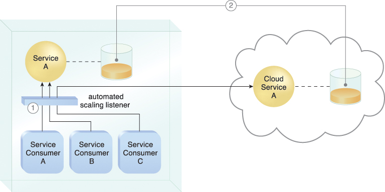
Figure 11.12 An automated scaling listener monitors the usage of on-premise Service A, and redirects Service Consumer C’s request to Service A’s redundant implementation in the cloud (Cloud Service A) once Service A’s usage threshold has been exceeded (1). A resource replication system is used to keep state management databases synchronized (2).
In addition to the automated scaling listener and resource replication, numerous other mechanisms can be used to automate the burst in and out dynamics for this architecture, depending primarily on the type of IT resource being scaled.
Cloud consumers are commonly charged for cloud-based storage space based on fixed-disk storage allocation, meaning the charges are predetermined by disk capacity and not aligned with actual data storage consumption. Figure 11.13 demonstrates this by illustrating a scenario in which a cloud consumer provisions a virtual server with the Windows Server operating system and three 150 GB hard drives. The cloud consumer is billed for using 450 GB of storage space after installing the operating system, even though it has not yet installed any software.
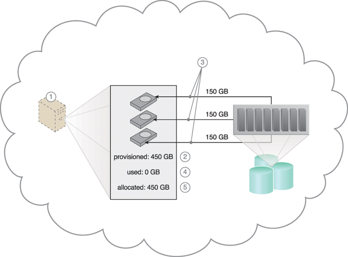
Figure 11.13 The cloud consumer requests a virtual server with three hard disks, each with a capacity of 150 GB (1). The virtual server is provisioned according to the elastic disk provisioning architecture, with a total of 450 GB of disk space (2). The 450 GB is allocated to the virtual server by the cloud provider (3). The cloud consumer has not installed any software yet, meaning the actual used space is currently 0 GB (4). Because the 450 GB are already allocated and reserved for the cloud consumer, it will be charged for 450 GB of disk usage as of the point of allocation (5).
The elastic disk provisioning architecture establishes a dynamic storage provisioning system that ensures that the cloud consumer is granularly billed for the exact amount of storage that it actually uses. This system uses thin-provisioning technology for the dynamic allocation of storage space, and is further supported by runtime usage monitoring to collect accurate usage data for billing purposes (Figure 11.14).
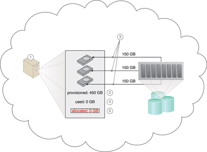
Figure 11.14 The cloud consumer requests a virtual server with three hard disks, each with a capacity of 150 GB (1). The virtual server is provisioned by this architecture with a total of 450 GB of disk space (2). The 450 GB are set as the maximum disk usage that is allowed for this virtual server, although no physical disk space has been reserved or allocated yet (3). The cloud consumer has not installed any software, meaning the actual used space is currently at 0 GB (4). Because the allocated disk space is equal to the actual used space (which is currently at zero), the cloud consumer is not charged for any disk space usage (5).
Thin-provisioning software is installed on virtual servers that process dynamic storage allocation via the hypervisor, while the pay-per-use monitor tracks and reports granular billing-related disk usage data (Figure 11.15).
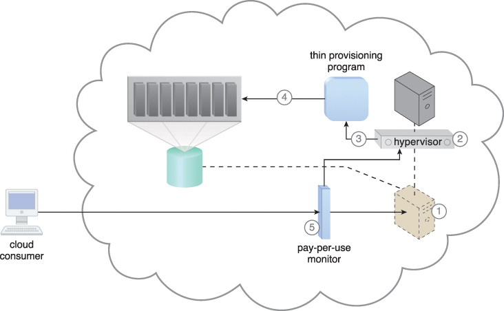
Figure 11.15 A request is received from a cloud consumer, and the provisioning of a new virtual server instance begins (1). As part of the provisioning process, the hard disks are chosen as dynamic or thin-provisioned disks (2). The hypervisor calls a dynamic disk allocation component to create thin disks for the virtual server (3). Virtual server disks are created via the thin-provisioning program and saved in a folder of near-zero size. The size of this folder and its files grow as operating applications are installed and additional files are copied onto the virtual server (4). The pay-per-use monitor tracks the actual dynamically allocated storage for billing purposes (5).
The following mechanisms can be included in this architecture in addition to the cloud storage device, virtual server, hypervisor, and pay-per-use monitor:
• Cloud Usage Monitor – Specialized cloud usage monitors can be used to track and log storage usage fluctuations.
• Resource Replication – Resource replication is part of an elastic disk provisioning system when conversion of dynamic thin-disk storage into static thick-disk storage is required.
Cloud storage devices are occasionally subject to failure and disruptions that are caused by network connectivity issues, controller or general hardware failure, or security breaches. A compromised cloud storage device’s reliability can have a ripple effect and cause impact failure across all of the services, applications, and infrastructure components in the cloud that are reliant on its availability.
The redundant storage architecture introduces a secondary duplicate cloud storage device as part of a failover system that synchronizes its data with the data in the primary cloud storage device. A storage service gateway diverts cloud consumer requests to the secondary device whenever the primary device fails (Figures 11.16 and 11.17).
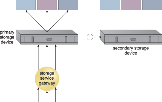
Figure 11.16 The primary cloud storage device is routinely replicated to the secondary cloud storage device (1).
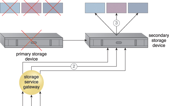
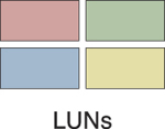
Figure 11.17 The primary storage becomes unavailable and the storage service gateway forwards the cloud consumer requests to the secondary storage device (2). The secondary storage device forwards the requests to the LUNs, allowing cloud consumers to continue to access their data (3).
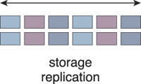
This cloud architecture primarily relies on a storage replication system that keeps the primary cloud storage device synchronized with its duplicate secondary cloud storage devices (Figure 11.18).
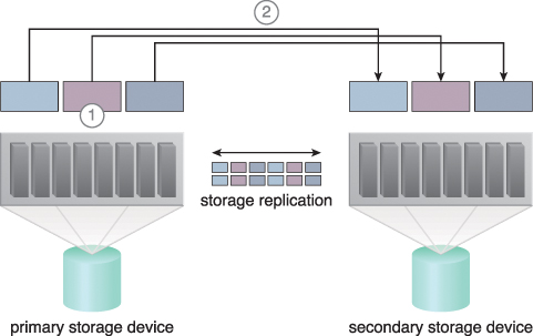
Figure 11.18 Storage replication is used to keep the redundant storage device synchronized with the primary storage device.
Cloud providers may locate secondary cloud storage devices in a different geographical region than the primary cloud storage device, usually for economic reasons. However, this can introduce legal concerns for some types of data. The location of the secondary cloud storage devices can dictate the protocol and method used for synchronization, as some replication transport protocols have distance restrictions.
Some cloud providers use storage devices with dual array and storage controllers to improve device redundancy, and place secondary storage devices in a different physical location for cloud balancing and disaster recovery purposes. In this case, cloud providers may need to lease a network connection via a third-party cloud provider in order to establish the replication between the two devices.
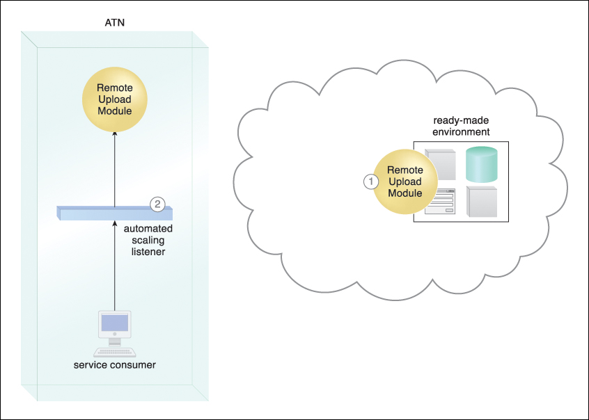
Figure 11.19 A cloud-based version of the on-premise Remote Upload Module service is deployed on ATN’s leased ready-made environment (1). The automated scaling listener monitors service consumer requests (2).
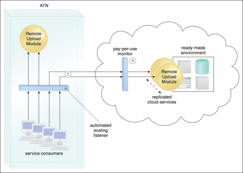
Figure 11.20 The automated scaling listener detects that service consumer usage has exceeded the local Remote Upload Module service’s usage threshold, and begins diverting excess requests to the cloud-based Remote Upload Module implementation (3). The cloud provider’s pay-per-use monitor tracks the requests received from the on-premise automated scaling listener to collect billing data, and Remote Upload Module cloud service instances are created on-demand via resource replication (4).