
12.1 Hypervisor Clustering Architecture
12.2 Load Balanced Virtual Server Instances Architecture
12.3 Non-Disruptive Service Relocation Architecture
12.4 Zero Downtime Architecture
12.5 Cloud Balancing Architecture
12.6 Resource Reservation Architecture
12.7 Dynamic Failure Detection and Recovery Architecture
12.8 Bare-Metal Provisioning Architecture
12.9 Rapid Provisioning Architecture
12.10 Storage Workload Management Architecture
The cloud technology architectures explored in this chapter represent distinct and sophisticated architectural layers, several of which can be built upon the more foundational environments established by the architectural models covered in Chapter 11.
Hypervisors can be responsible for creating and hosting multiple virtual servers. Because of this dependency, any failure conditions that affect a hypervisor can cascade to its virtual servers (Figure 12.1).
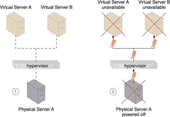
Figure 12.1 Physical Server A is hosting a hypervisor that hosts Virtual Servers A and B (1). When Physical Server A fails, the hypervisor and two virtual servers consequently fail as well (2).
Heartbeats

Heartbeats are system-level messages exchanged between hypervisors, hypervisors and virtual servers, and hypervisors and VIMs.
The hypervisor clustering architecture establishes a high-availability cluster of hypervisors across multiple physical servers. If a given hypervisor or its underlying physical server becomes unavailable, the hosted virtual servers can be moved to another physical server or hypervisor to maintain runtime operations (Figure 12.2).
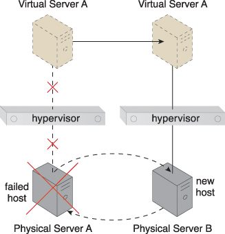
Figure 12.2 Physical Server A becomes unavailable and causes its hypervisor to fail. Virtual Server A is migrated to Physical Server B, which has another hypervisor that is part of the cluster to which Physical Server A belongs.
The hypervisor cluster is controlled via a central VIM, which sends regular heartbeat messages to the hypervisors to confirm that they are up and running. Unacknowledged heartbeat messages cause the VIM to initiate the live VM migration program, in order to dynamically move the affected virtual servers to a new host.
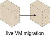
Live VM migration
Live VM migration is a system that is capable of relocating virtual servers or virtual server instances at runtime.
The hypervisor cluster uses a shared cloud storage device to live-migrate virtual servers, as illustrated in Figures 12.3 to 12.6.
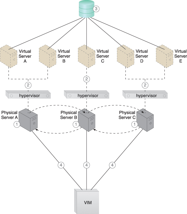
Figure 12.3 Hypervisors are installed on Physical Servers A, B, and C (1). Virtual servers are created by the hypervisors (2). A shared cloud storage device containing virtual server configuration files is positioned in a shared cloud storage device for access by all hypervisors (3). The hypervisor cluster is enabled on the three physical server hosts via a central VIM (4).
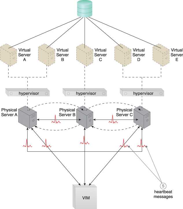
Figure 12.4 The physical servers exchange heartbeat messages with one another and the VIM according to a pre-defined schedule (5).
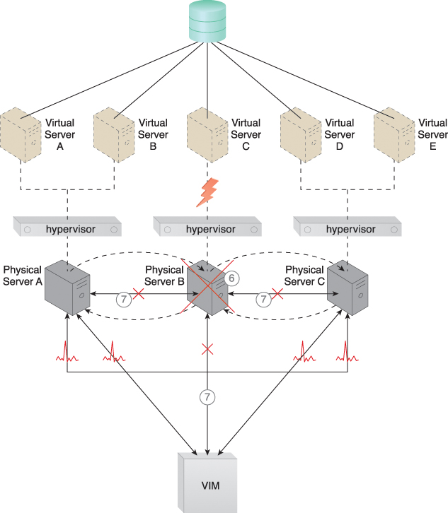
Figure 12.5 Physical Server B fails and becomes unavailable, jeopardizing Virtual Server C (6). The other physical servers and the VIM stop receiving heartbeat messages from Physical Server B (7).
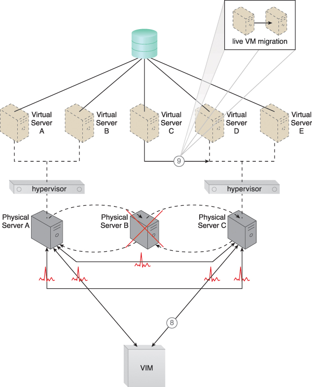
Figure 12.6 The VIM chooses Physical Server C as the new host to take ownership of Virtual Server C after assessing the available capacity of other hypervisors in the cluster (8). Virtual Server C is live-migrated to the hypervisor running on Physical Server C, where restarting may be necessary before normal operations can be resumed (9).
In addition to the hypervisor and resource cluster mechanisms that form the core of this architectural model and the virtual servers that are protected by the clustered environment, the following mechanisms can be incorporated:
• Logical Network Perimeter – The logical boundaries created by this mechanism ensure that none of the hypervisors of other cloud consumers are accidentally included in a given cluster.
• Resource Replication – Hypervisors in the same cluster inform one another about their status and availability. Updates on any changes that occur in the cluster, such as the creation or deletion of a virtual switch, need to be replicated to all of the hypervisors via the VIM.
Keeping cross-server workloads evenly balanced between physical servers whose operation and management are isolated can be challenging. A physical server can easily end up hosting more virtual servers or receive larger workloads than its neighboring physical servers (Figure 12.7). Both physical server over and under-utilization can increase dramatically over time, leading to on-going performance challenges (for over-utilized servers) and constant waste (for the lost processing potential of under-utilized servers).
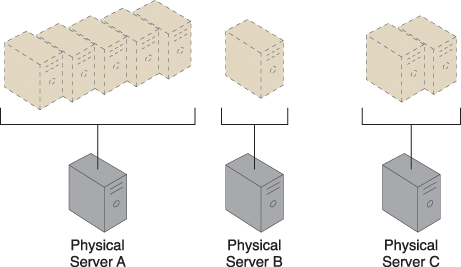
Figure 12.7 Three physical servers have to host different quantities of virtual server instances, leading to both over-utilized and under-utilized servers.
The load balanced virtual server instances architecture establishes a capacity watchdog system that dynamically calculates virtual server instances and associated workloads, before distributing the processing across available physical server hosts (Figure 12.8).

Figure 12.8 The virtual server instances are more evenly distributed across the physical server hosts.
The capacity watchdog system is comprised of a capacity watchdog cloud usage monitor, the live VM migration program, and a capacity planner. The capacity watchdog monitor tracks physical and virtual server usage and reports any significant fluctuations to the capacity planner, which is responsible for dynamically calculating physical server computing capacities against virtual server capacity requirements. If the capacity planner decides to move a virtual server to another host to distribute the workload, the live VM migration program is signaled to move the virtual server (Figures 12.9 to 12.11).
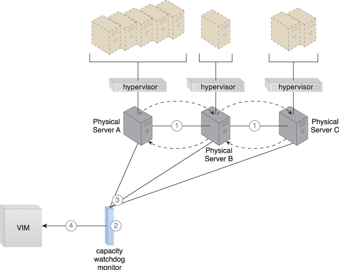
Figure 12.9 The hypervisor cluster architecture provides the foundation upon which the load-balanced virtual server architecture is built (1). Policies and thresholds are defined for the capacity watchdog monitor (2), which compares physical server capacities with virtual server processing (3). The capacity watchdog monitor reports an over-utilization to the VIM (4).
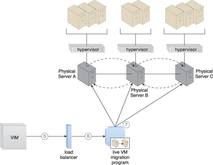
Figure 12.10 The VIM signals the load balancer to redistribute the workload based on pre-defined thresholds (5). The load balancer initiates the live VM migration program to move the virtual servers (6). Live VM migration moves the selected virtual servers from one physical host to another (7).
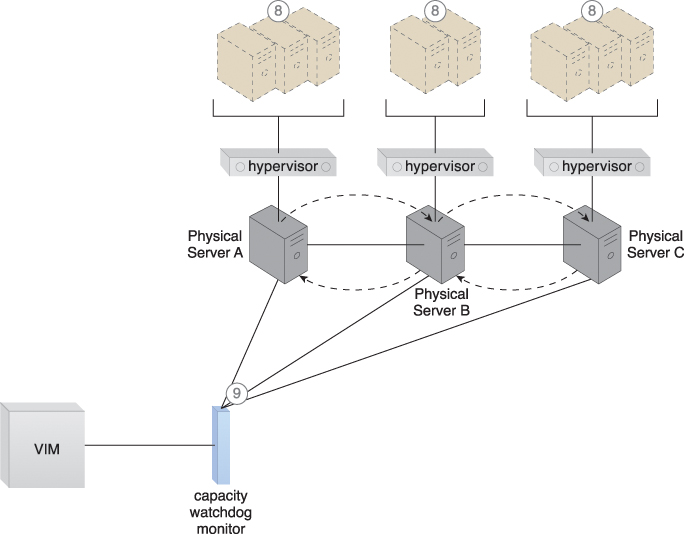
Figure 12.11 The workload is balanced across the physical servers in the cluster (8). The capacity watchdog continues to monitor the workload and resource consumption (9).
The following mechanisms can be included in this architecture, in addition to the hypervisor, resource clustering, virtual server, and (capacity watchdog) cloud usage monitor:
• Automated Scaling Listener – The automated scaling listener may be used to initiate the process of load balancing and to dynamically monitor workload coming to the virtual servers via the hypervisors.
• Load Balancer – The load balancer mechanism is responsible for distributing the workload of the virtual servers between the hypervisors.
• Logical Network Perimeter – A logical network perimeter ensures that the destination of a given relocated virtual server is in compliance with SLA and privacy regulations.
• Resource Replication – The replication of virtual server instances may be required as part of the load balancing functionality.
A cloud service can become unavailable for a number of reasons, such as:
• runtime usage demands that exceed its processing capacity
• a maintenance update that mandates a temporary outage
• permanent migration to a new physical server host
Cloud service consumer requests are usually rejected if a cloud service becomes unavailable, which can potentially result in exception conditions. Rendering the cloud service temporarily unavailable to cloud consumers is not preferred even if the outage is planned.
The non-disruptive service relocation architecture establishes a system by which a predefined event triggers the duplication or migration of a cloud service implementation at runtime, thereby avoiding any disruption. Instead of scaling cloud services in or out with redundant implementations, cloud service activity can be temporarily diverted to another hosting environment at runtime by adding a duplicate implementation onto a new host. Similarly, cloud service consumer requests can be temporarily redirected to a duplicate implementation when the original implementation needs to undergo a maintenance outage. The relocation of the cloud service implementation and any cloud service activity can also be permanent to accommodate cloud service migrations to new physical server hosts.
A key aspect of the underlying architecture is that the new cloud service implementation is guaranteed to be successfully receiving and responding to cloud service consumer requests before the original cloud service implementation is deactivated or removed. A common approach is for live VM migration to move the entire virtual server instance that is hosting the cloud service. The automated scaling listener and/or load balancer mechanisms can be used to trigger a temporary redirection of cloud service consumer requests, in response to scaling and workload distribution requirements. Either mechanism can contact the VIM to initiate the live VM migration process, as shown in Figures 12.12 to 12.14.
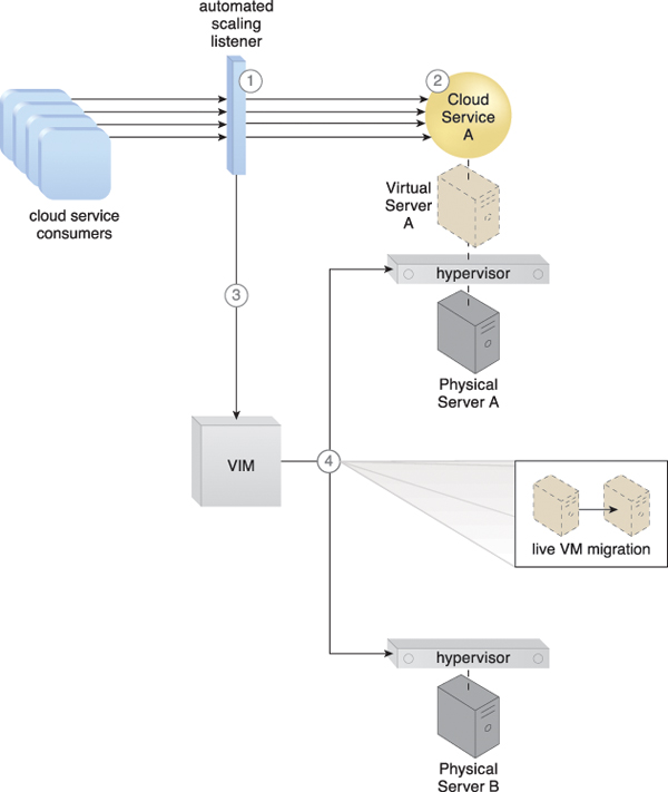
Figure 12.12 The automated scaling listener monitors the workload for a cloud service (1). The cloud service’s predefined threshold is reached as the workload increases (2), causing the automated scaling listener to signal the VIM to initiate relocation (3). The VIM uses the live VM migration program to instruct both the origin and destination hypervisors to carry out runtime relocation (4).
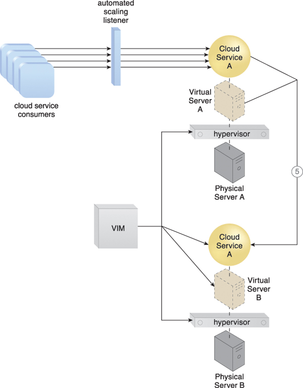
Figure 12.13 A second copy of the virtual server and its hosted cloud service are created via the destination hypervisor on Physical Server B (5).
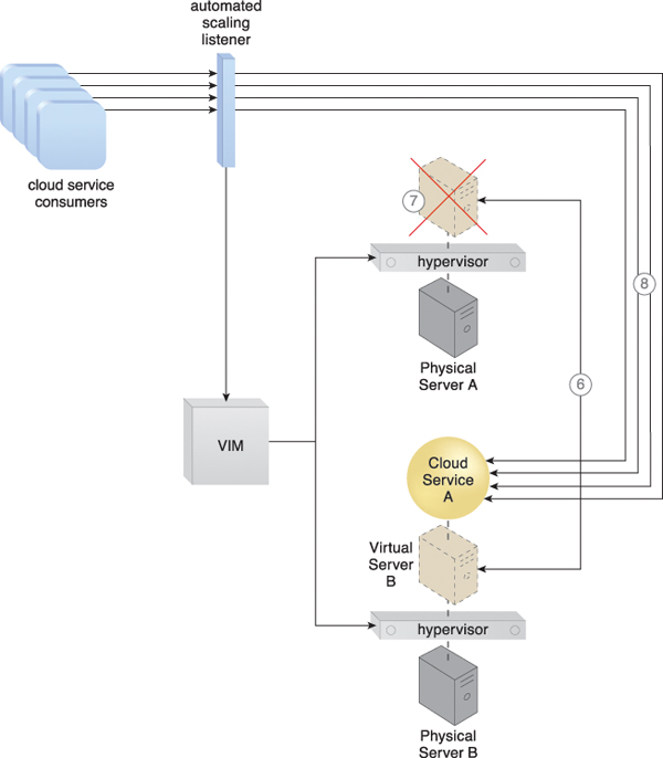
Figure 12.14 The state of both virtual server instances is synchronized (6). The first virtual server instance is removed from Physical Server A after cloud service consumer requests are confirmed to be successfully exchanged with the cloud service on Physical Server B (7). Cloud service consumer requests are now only sent to the cloud service on Physical Server B (8).
Virtual server migration can occur in one of the following two ways, depending on the location of the virtual server’s disks and configuration:
• A copy of the virtual server disks is created on the destination host, if the virtual server disks are stored on a local storage device or non-shared remote storage devices attached to the source host. After the copy has been created, both virtual server instances are synchronized and virtual server files are removed from the origin host.
• Copying the virtual server disks is unnecessary if the virtual server’s files are stored on a remote storage device that is shared between origin and destination hosts. Ownership of the virtual server is simply transferred from the origin to the destination physical server host, and the virtual server’s state is automatically synchronized.
This architecture can be supported by the persistent virtual network configurations architecture, so that the defined network configurations of migrated virtual servers are preserved to retain connection with the cloud service consumers.
Besides the automated scaling listener, load balancer, cloud storage device, hypervisor, and virtual server, other mechanisms that can be part of this architecture include the following:
• Cloud Usage Monitor – Different types of cloud usage monitors can be used to continuously track IT resource usage and system activity.
• Pay-Per-Use Monitor – The pay-per-use monitor is used to collect data for service usage cost calculations for IT resources at both source and destination locations.
• Resource Replication – The resource replication mechanism is used to instantiate the shadow copy of the cloud service at its destination.
• SLA Management System – This management system is responsible for processing SLA data provided by the SLA monitor to obtain cloud service availability assurances, both during and after cloud service duplication or relocation.
• SLA Monitor – This monitoring mechanism collects the SLA information required by the SLA management system, which may be relevant if availability guarantees rely on this architecture.
Note
The non-disruptive service relocation technology architecture conflicts and cannot be applied together with the direct I/O access architecture covered in Chapter 13. A virtual server with direct I/O access is locked into its physical server host and cannot be moved to other hosts in this fashion.
A physical server naturally acts as a single point of failure for the virtual servers it hosts. As a result, when the physical server fails or is compromised, the availability of any (or all) hosted virtual servers can be affected. This makes the issuance of zero downtime guarantees by a cloud provider to cloud consumers challenging.
The zero downtime architecture establishes a sophisticated failover system that allows virtual servers to be dynamically moved to different physical server hosts, in the event that their original physical server host fails (Figure 12.15).
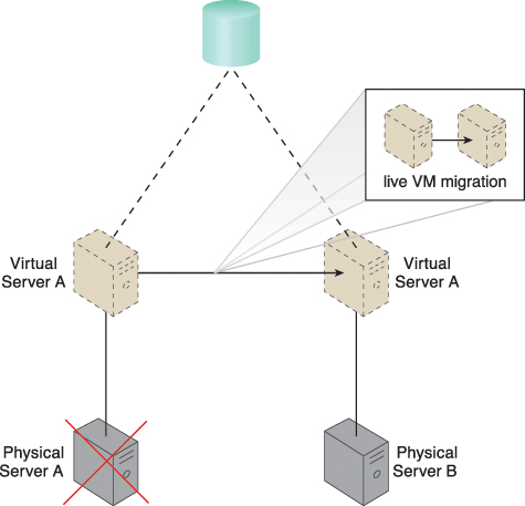
Figure 12.15 Physical Server A fails triggering the live VM migration program to dynamically move Virtual Server A to Physical Server B.
Multiple physical servers are assembled into a group that is controlled by a fault tolerance system capable of switching activity from one physical server to another, without interruption. The live VM migration component is typically a core part of this form of high availability cloud architecture.
The resulting fault tolerance assures that, in case of physical server failure, hosted virtual servers will be migrated to a secondary physical server. All virtual servers are stored on a shared volume (as per the persistent virtual network configuration architecture) so that other physical server hosts in the same group can access their files.
Besides the failover system, cloud storage device, and virtual server mechanisms, the following mechanisms can be part of this architecture:
• Audit Monitor – This mechanism may be required to check whether the relocation of virtual servers also relocates hosted data to prohibited locations.
• Cloud Usage Monitor – Incarnations of this mechanism are used to monitor the actual IT resource usage of cloud consumers to help ensure that virtual server capacities are not exceeded.
• Hypervisor – The hypervisor of each affected physical server hosts the affected virtual servers.
• Logical Network Perimeter – Logical network perimeters provide and maintain the isolation that is required to ensure that each cloud consumer remains within its own logical boundary subsequent to virtual server relocation.
• Resource Cluster – The resource cluster mechanism is applied to create different types of active-active cluster groups that collaboratively improve the availability of virtual server-hosted IT resources.
• Resource Replication – This mechanism can create the new virtual server and cloud service instances upon primary virtual server failure.
The cloud balancing architecture establishes a specialized architectural model in which IT resources can be load-balanced across multiple clouds.
The cross-cloud balancing of cloud service consumer requests can help:
• improve the performance and scalability of IT resources
• increase the availability and reliability of IT resources
• improve load-balancing and IT resource optimization
Cloud balancing functionality is primarily based on the combination of the automated scaling listener and failover system mechanisms (Figure 12.16). Many more components (and possibly other mechanisms) can be part of a complete cloud balancing architecture.
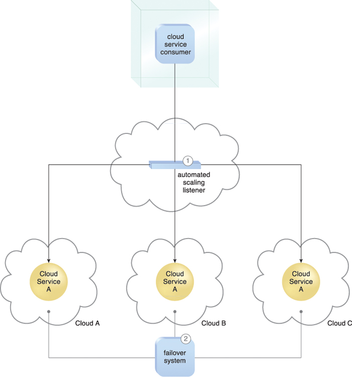
Figure 12.16 An automated scaling listener controls the cloud balancing process by routing cloud service consumer requests to redundant implementations of Cloud Service A distributed across multiple clouds (1). The failover system instills resiliency within this architecture by providing cross-cloud failover (2).
As a starting point, the two mechanisms are utilized as follows:
• The automated scaling listener redirects cloud service consumer requests to one of several redundant IT resource implementations, based on current scaling and performance requirements.
• The failover system ensures that redundant IT resources are capable of cross-cloud failover in the event of a failure within an IT resource or its underlying hosting environment. IT resource failures are announced so that the automated scaling listener can avoid inadvertently routing cloud service consumer requests to unavailable or unstable IT resources.
For a cloud balancing architecture to function effectively, the automated scaling listener needs to be aware of all redundant IT resource implementations within the scope of the cloud balanced architecture.
Note that if the manual synchronization of cross-cloud IT resource implementations is not possible, the resource replication mechanism may need to be incorporated to automate the synchronization.
Depending on how IT resources are designed for shared usage and depending on their available levels of capacity, concurrent access can lead to a runtime exception condition called resource constraint. A resource constraint is a condition that occurs when two or more cloud consumers have been allocated to share an IT resource that does not have the capacity to accommodate the total processing requirements of the cloud consumers. As a result, one or more of the cloud consumers encounter degraded performance or may be rejected altogether. The cloud service itself may go down, resulting in all cloud consumers being rejected.
Other types of runtime conflicts can occur when an IT resource (especially one not specifically designed to accommodate sharing) is concurrently accessed by different cloud service consumers. For example, nested and sibling resource pools introduce the notion of resource borrowing, whereby one pool can temporarily borrow IT resources from other pools. A runtime conflict can be triggered when the borrowed IT resource is not returned due to prolonged usage by the cloud service consumer that is borrowing it. This can inevitably lead back to the occurrence of resource constraints.
The resource reservation architecture establishes a system whereby one of the following is set aside exclusively for a given cloud consumer (Figures 12.17 to 12.19):
• single IT resource
• portion of an IT resource
• multiple IT resources
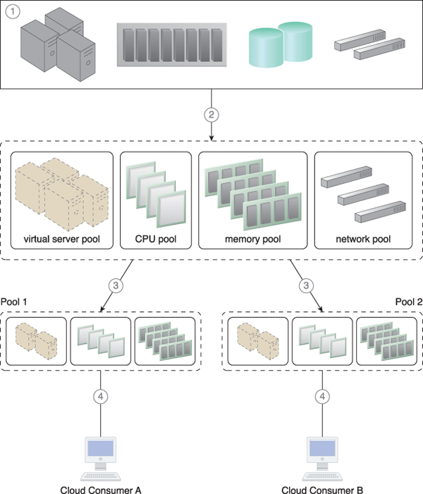
Figure 12.17 A physical resource group is created (1), from which a parent resource pool is created as per the resource pooling architecture (2). Two smaller child pools are created from the parent resource pool, and resource limits are defined using the resource management system (3). Cloud consumers are provided with access to their own exclusive resource pools (4).

Figure 12.18 An increase in requests from Cloud Consumer A results in more IT resources being allocated to that cloud consumer (5), meaning some IT resources need to be borrowed from Pool 2. The amount of borrowed IT resources is confined by the resource limit that was defined in Step 3, to ensure that Cloud Consumer B will not face any resource constraints (6).
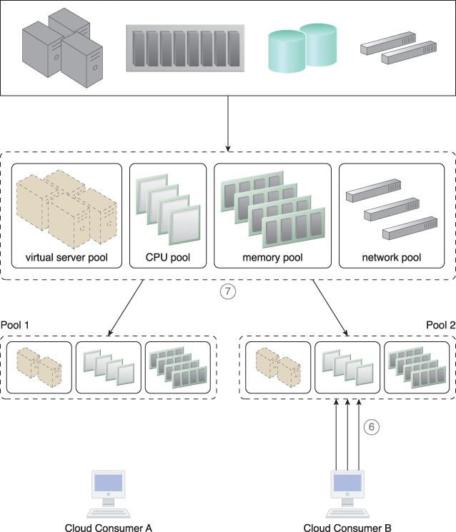
Figure 12.19 Cloud Consumer B now imposes more requests and usage demands and may soon need to utilize all available IT resources in the pool (6). The resource management system forces Pool 1 to release the IT resources and move them back to Pool 2 to become available for Cloud Consumer B (7).
This protects cloud consumers from each other by avoiding the aforementioned resource constraint and resource borrowing conditions.
The creation of an IT resource reservation system can require involving the resource management system mechanism, which is used to define the usage thresholds for individual IT resources and resource pools. Reservations lock the amount of IT resources that each pool needs to keep, with the balance of the pool’s IT resources still available for sharing and borrowing. The remote administration system mechanism is also used to enable front-end customization, so that cloud consumers have administration controls for the management of their reserved IT resource allocations.
The types of mechanisms that are commonly reserved within this architecture are cloud storage devices and virtual servers. Other mechanisms that may be part of the architecture can include:
• Audit Monitor – The audit monitor is used to check whether the resource reservation system is complying with cloud consumer auditing, privacy, and other regulatory requirements. For example, it may track the geographical location of reserved IT resources.
• Cloud Usage Monitor – A cloud usage monitor may oversee the thresholds that trigger the allocation of reserved IT resources.
• Hypervisor – The hypervisor mechanism may apply reservations for different cloud consumers to ensure that they are correctly allocated to their guaranteed IT resources.
• Logical Network Perimeter – This mechanism establishes the boundaries necessary to ensure that reserved IT resources are made exclusively available to cloud consumers.
• Resource Replication – This component needs to stay informed about each cloud consumer’s limits for IT resource consumption, in order to replicate and provision new IT resource instances expediently.
Cloud-based environments can be comprised of vast quantities of IT resources that are simultaneously accessed by numerous cloud consumers. Any of those IT resources can experience failure conditions that require more than manual intervention to resolve. Manually administering and solving IT resource failures is generally inefficient and impractical.
The dynamic failure detection and recovery architecture establishes a resilient watchdog system to monitor and respond to a wide range of pre-defined failure scenarios (Figures 12.20 and 12.21). This system notifies and escalates the failure conditions that it cannot automatically resolve itself. It relies on a specialized cloud usage monitor called the intelligent watchdog monitor to actively track IT resources and take pre-defined actions in response to pre-defined events.

Figure 12.20 The intelligent watchdog monitor keeps track of cloud consumer requests (1) and detects that a cloud service has failed (2).
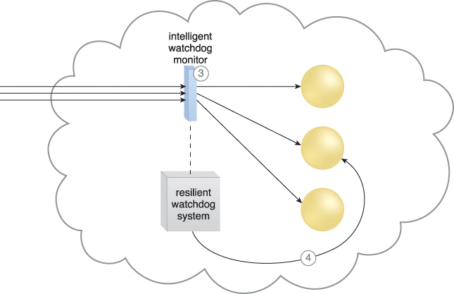
Figure 12.21 The intelligent watchdog monitor notifies the watchdog system (3), which restores the cloud service based on pre-defined policies. The cloud service resumes its runtime operation (4).
The resilient watchdog system performs the following five core functions:
• watching
• deciding upon an event
• acting upon an event
• reporting
• escalating
Sequential recovery policies can be defined for each IT resource to determine the steps that the intelligent watchdog monitor needs to take when a failure condition occurs. For example, a recovery policy can state that one recovery attempt needs to be automatically carried out before issuing a notification (Figure 12.22).
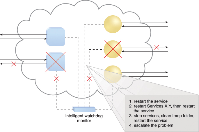
Figure 12.22 In the event of a failure, the intelligent watchdog monitor refers to its pre-defined policies to recover the cloud service step-by-step, escalating the process when a problem proves to be deeper than expected.
Some of the actions the intelligent watchdog monitor commonly takes to escalate an issue include:
• running a batch file
• sending a console message
• sending a text message
• sending an email message
• sending an SNMP trap
• logging a ticket
There are varieties of programs and products that can act as intelligent watchdog monitors. Most can be integrated with standard ticketing and event management systems.
This architectural model can further incorporate the following mechanisms:
• Audit Monitor – This mechanism is used to track whether data recovery is carried out in compliance with legal or policy requirements.
• Failover System – The failover system mechanism is usually used during the initial attempts to recover failed IT resources.
• SLA Management System and SLA Monitor – Since the functionality achieved by applying this architecture is closely associated with SLA guarantees, the system commonly relies on the information that is managed and processed by these mechanisms.
Remotely provisioning servers is common because remote management software is usually native to the operating system of most physical servers. However, access to conventional remote management programs is unavailable for bare-metal servers—physical servers that do not have pre-installed operating systems or any other software.
Most contemporary physical servers provide the option of installing remote management support in the server’s ROM. This is offered by some vendors through an expansion card while others have the components already integrated into the chipset. The bare-metal provisioning architecture establishes a system that utilizes this feature with specialized service agents, which are used to discover and effectively provision entire operating systems remotely.
The remote management software that is integrated with the server’s ROM becomes available upon server start-up. A Web-based or proprietary user-interface, like the portal provided by the remote administration system, is usually used to connect to the physical server’s native remote management interface. The IP address of the remote management interface can be configured manually, through the default IP, or alternatively set through the configuration of a DHCP service. IP addresses in IaaS platforms can be forwarded directly to cloud consumers so that they can perform bare-metal operating system installations independently.
Although remote management software is used to enable connections to physical server consoles and deploy operating systems, there are two common concerns about its usage:
• Manual deployment on multiple servers can be vulnerable to inadvertent human and configuration errors.
• Remote management software can be time-intensive and require significant runtime IT resource processing.
The bare-metal provisioning system addresses these issues by using the following components:
• Discovery Agent – A type of monitoring agent that searches and finds available physical servers to be assigned to cloud consumers.
• Deployment Agent – A management agent that is installed into a physical server’s memory, to be positioned as a client for the bare-metal provisioning deployment system.
• Discovery Section – A software component that scans the network and locates available physical servers with which to connect.
• Management Loader – The component that connects to the physical server and loads the management options for the cloud consumer.
• Deployment Component – The component responsible for installing the operating system on the selected physical servers.
The bare-metal provisioning system provides an auto-deployment feature that allows cloud consumers to connect to the deployment software and provision more than one server or operating system at the same time. The central deployment system connects to the servers via their management interfaces, and uses the same protocol to upload and operate as an agent in the physical server’s RAM. The bare-metal server then becomes a raw client with a management agent installed, and the deployment software uploads the required setup files to deploy the operating system (Figures 12.23 and 12.24).
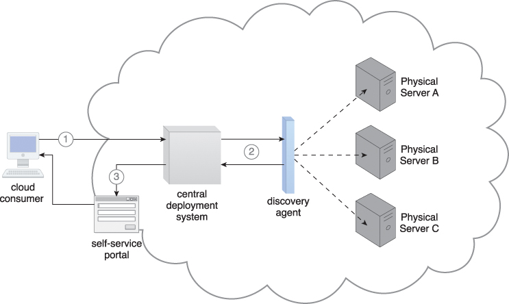
Figure 12.23 The cloud consumer connects to the deployment solution (1) to perform a search using the discovery agent (2). The available physical servers are shown to the cloud consumer (3).
Deployment images, operating system deployment automation, or unattended deployment and post installation configuration scripts can be used via the intelligent automation engine and self-service portal to extend this functionality.
The following additional mechanisms can be part of this architecture:
• Cloud Storage Device – This mechanism stores operating system templates and installation files, as well as deployment agents and deployment packages for the provisioning system.
• Hypervisor – The deployment of hypervisors on physical servers as part of the operating system provisioning can be required.
• Logical Network Perimeter – Logical network perimeter boundaries help ensure that raw physical servers can only be accessed by authorized cloud consumers.
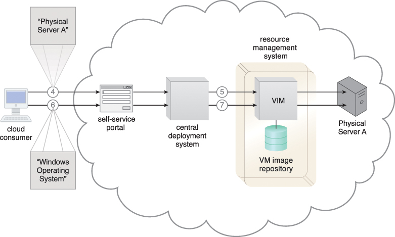
Figure 12.24 The cloud consumer selects a physical server to provision (4). The deployment agent is loaded to the physical server’s RAM via the remote management system (5). The cloud consumer selects an operating system and method of configuration via the deployment solution (6). The operating system is installed and the server becomes operational (7).
• Resource Replication – This mechanism is implemented for the replication of IT resources by deploying a new hypervisor on a physical server to balance the hypervisor workload during or after provisioning.
• SLA Management System – This management system ensures that the availability of physical bare-metal servers is in accordance with pre-defined SLA stipulations.
A conventional provisioning process can involve a number of tasks that are traditionally completed manually by administrators and technology experts that prepare the requested IT resources as per pre-packaged specifications or custom client requests. In cloud environments, where higher volumes of customers are serviced and where the average customer requests higher volumes of IT resources, manual provisioning processes are inadequate and can even lead to unreasonable risk due to human error and inefficient response times.
For example, a cloud consumer that requests the installation, configuration, and updating of twenty-five Windows servers with several applications requires that half of the applications be identical installations, while the other half be customized. Each operating system deployment can take up to 30 minutes, followed by additional time for security patches and operating system updates that require server rebooting. The applications finally need to be deployed and configured. Using a manual or semi-automated approach requires excessive amounts of time, and introduces a probability of human error that increases with each installation.
The rapid provisioning architecture establishes a system that automates the provisioning of a wide range of IT resources, either individually or as a collective. The underlying technology architecture for rapid IT resource provisioning can be sophisticated and complex, and relies on a system comprised of an automated provisioning program, rapid provisioning engine, and scripts and templates for on-demand provisioning.
Beyond the components displayed in Figure 12.25, many additional architectural artifacts are available to coordinate and automate the different aspects of IT resource provisioning, such as:
• Server Templates – Templates of virtual image files that are used to automate the instantiation of new virtual servers.
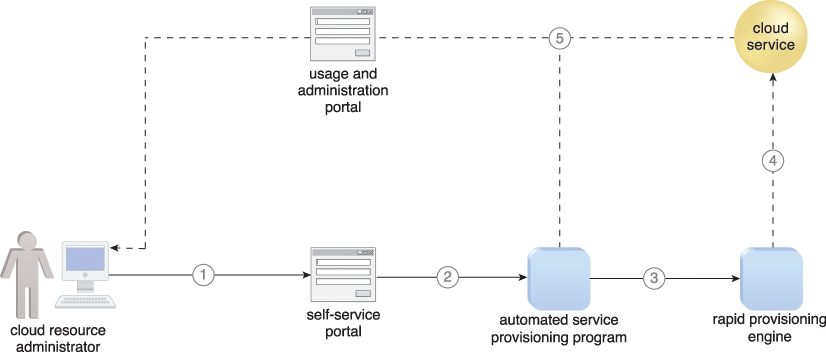
Figure 12.25 A cloud resource administrator requests a new cloud service through the self-service portal (1). The self-service portal passes the request to the automated service provisioning program installed on the virtual server (2), which passes the necessary tasks to be performed to the rapid provisioning engine (3). The rapid provisioning engine announces when the new cloud service is ready (4). The automated service provisioning program finalizes and publishes the cloud service on the usage and administration portal for cloud consumer access (5).
• Server Images – These images are similar to virtual server templates, but are used to provision physical servers.
• Application Packages – Collections of applications and other software that are packaged for automated deployment.
• Application Packager – The software used to create application packages.
• Custom Scripts – Scripts that automate administrative tasks, as part of an intelligent automation engine.
• Sequence Manager – A program that organizes sequences of automated provisioning tasks.
• Sequence Logger – A component that logs the execution of automated provisioning task sequences.
• Operating System Baseline – A configuration template that is applied after the operating system is installed, to quickly prepare it for usage.
• Application Configuration Baseline – A configuration template with the settings and environmental parameters that are needed to prepare new applications for use.
• Deployment Data Store – The repository that stores virtual images, templates, scripts, baseline configurations, and other related data.
The following step-by-step description helps provide some insight into the inner workings of a rapid provisioning engine, involving a number of the previously listed system components:
1. A cloud consumer requests a new server through the self-service portal.
2. The sequence manager forwards the request to the deployment engine for the preparation of an operating system.
3. The deployment engine uses the virtual server templates for provisioning if the request is for a virtual server. Otherwise, the deployment engine sends the request to provision a physical server.
4. The pre-defined image for the requested type of operating system is used for the provisioning of the operating system, if available. Otherwise, the regular deployment process is executed to install the operating system.
5. The deployment engine informs the sequence manager when the operating system is ready.
6. The sequence manager updates and sends the logs to the sequence logger for storage.
7. The sequence manager requests that the deployment engine apply the operating system baseline to the provisioned operating system.
8. The deployment engine applies the requested operating system baseline.
9. The deployment engine informs the sequence manager that the operating system baseline has been applied.
10. The sequence manager updates and sends the logs of completed steps to the sequence logger for storage.
11. The sequence manager requests that the deployment engine install the applications.
12. The deployment engine deploys the applications on the provisioned server.
13. The deployment engine informs the sequence manager that the applications have been installed.
14. The sequence manager updates and sends the logs of completed steps to the sequence logger for storage.
15. The sequence manager requests that the deployment engine apply the application’s configuration baseline.
16. The deployment engine applies the configuration baseline.
17. The deployment engine informs the sequence manager that the configuration baseline has been applied.
18. The sequence manager updates and sends the logs of completed steps to the sequence logger for storage.
The cloud storage device mechanism is used to provide storage for application baseline information, templates, and scripts, while the hypervisor rapidly creates, deploys, and hosts the virtual servers that are either provisioned themselves, or host other provisioned IT resources. The resource replication mechanism is usually used to generate replicated instances of IT resources in response to rapid provisioning requirements.
Over-utilized cloud storage devices increase the workload on the storage controller and can cause a range of performance challenges. Conversely, cloud storage devices that are under-utilized are wasteful due to lost processing and storage capacity potential (Figure 12.26).
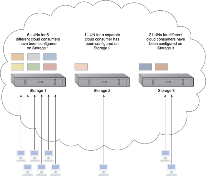
Figure 12.26 An unbalanced cloud storage architecture has six storage LUNs in Storage 1 for cloud consumers to use, while Storage 2 is hosting one LUN and Storage 3 is hosting two. The majority of the workload ends up with Storage 1, since it is hosting the most LUNs.
LUN migration
LUN migration is a specialized storage program that is used to move LUNs from one storage device to another without interruption, while remaining transparent to cloud consumers.

The storage workload management architecture enables LUNs to be evenly distributed across available cloud storage devices, while a storage capacity system is established to ensure that runtime workloads are evenly distributed across the LUNs (Figure 12.27).
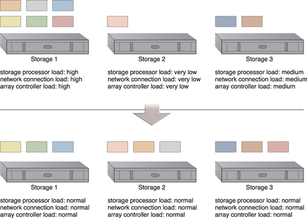
Figure 12.27 LUNs are dynamically distributed across cloud storage devices, resulting in more even distribution of associated types of workloads.
Combining cloud storage devices into a group allows LUN data to be distributed between available storage hosts equally. A storage management system is configured and an automated scaling listener is positioned to monitor and equalize runtime workloads among the grouped cloud storage devices, as illustrated in Figures 12.28 to 12.30.
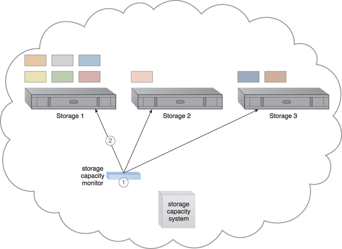
Figure 12.28 The storage capacity system and storage capacity monitor are configured to survey three storage devices in realtime, whose workload and capacity thresholds are pre-defined (1). The storage capacity monitor determines that the workload on Storage 1 is reaching its threshold (2).
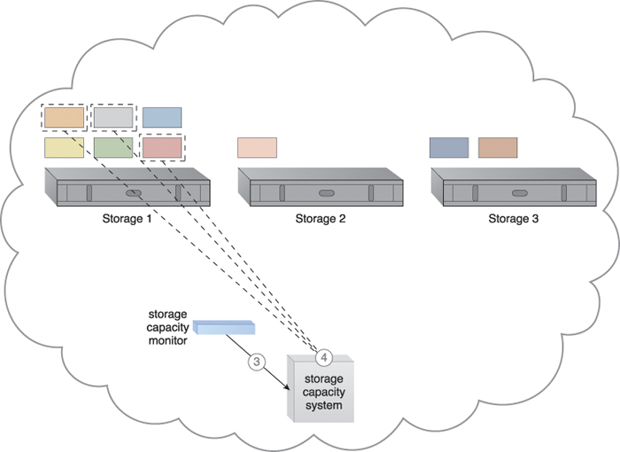
Figure 12.29 The storage capacity monitor informs the storage capacity system that Storage 1 is over-utilized (3). The storage capacity system identifies the LUNs to be moved from Storage 1 (4).

Figure 12.30 The storage capacity system calls for LUN migration to move some of the LUNs from Storage 1 to the other two storage devices (5). LUN migration transitions LUNs to Storage 2 and 3 to balance the workload (6).
The storage capacity system can keep the hosting storage device in power-saving mode for the periods when the LUNs are being accessed less frequently or only at specific times.
Some other mechanisms that can be included in the storage workload management architecture to accompany the cloud storage device are as follows:
• Audit Monitor – This monitoring mechanism is used to check for compliance with regulatory, privacy, and security requirements, since the system established by this architecture can physically relocate data.
• Automated Scaling Listener – The automated scaling listener is used to watch and respond to workload fluctuations.
• Cloud Usage Monitor – In addition to the capacity workload monitor, specialized cloud usage monitors are used to track LUN movements and collect workload distribution statistics.
• Load Balancer – This mechanism can be added to horizontally balance workloads across available cloud storage devices.
• Logical Network Perimeter – Logical network perimeters provide levels of isolation so that cloud consumer data that undergoes relocation remains inaccessible to unauthorized parties.

Figure 12.31 A load-balancing service agent routes cloud service consumer requests according to a pre-defined algorithm (1). Requests are received by the local or external automated scaling listener (2A, 2B), which forward each request to a cloud service implementation (3). Failover system monitors are used to detect and respond to cloud service failure (4).