We’ve seen that if we oscillate one end of a long rope, we generate a wave that travels down the rope and whose frequency is the frequency with which we oscillate.
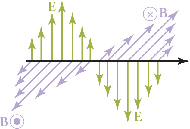
You can think of an electromagnetic wave in a similar way: An oscillating electric charge generates an electromagnetic (EM) wave, which is composed of oscillating electric and magnetic fields. These fields oscillate with the same frequency at which the electric charge that created the wave oscillated. The fields oscillate in phase with each other, perpendicular to each other and to the direction of propagation. For this reason, electromagnetic waves are transverse waves. The direction in which the wave’s electric field oscillates is called the direction of polarization of the wave. Most EM waves have electric fields oscillating in all perpendicular directions to propagation equally and are thus unpolarized.
Unlike waves on a rope or sound waves, electromagnetic waves do not require a material medium to propagate; they can travel through empty space (vacuum). When an EM wave travels through vacuum, its speed is a constant. It is one of the fundamental constants of nature and a value you should memorize for the MCAT:
Speed of Light in Vacuum
c = 3 × 10⁸ 
![]()
All electromagnetic waves, regardless of frequency, travel through vacuum at this speed. The most important equation for waves, v = λf, is also true for electromagnetic waves. For EM waves traveling through vacuum, v = c, so the equation becomes c = λf.
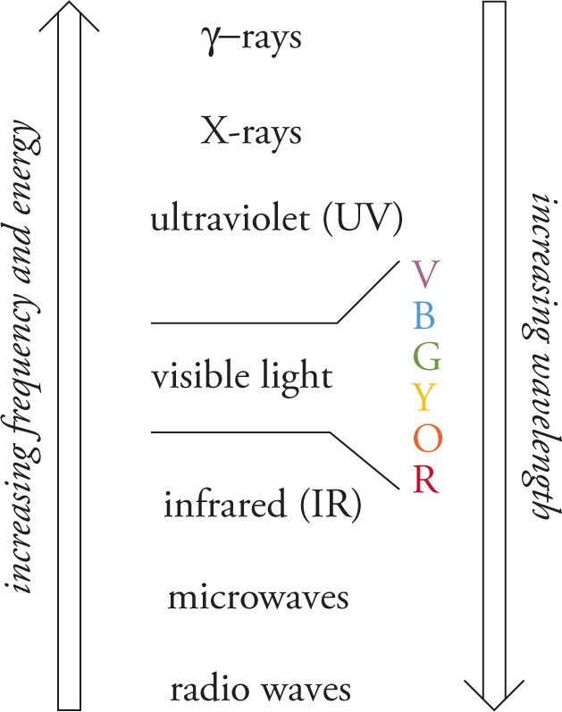
The frequencies for electromagnetic waves span a huge range, and different ranges have been given specific names. This assignment of names to specific regions based on frequency (or wavelength) is known as the electromagnetic spectrum and is shown here.
Notice that visible light occupies only a small part of the electromagnetic spectrum. When waves from all over the visible spectrum are mixed together, the resulting light is perceived as white. You should memorize the order of the colors of the visible spectrum from lowest frequency (longest wavelength) to highest frequency (shortest wavelength): ROYGBV (“Roy-Gee-Biv”), which stands for red, orange, yellow, green, blue, and violet. In terms of wavelengths, violet light has a wavelength (in vacuum) of about 400 nm and red light has a wavelength of about 700 nm; the other colors are in between.
When electromagnetic radiation interacts with matter (absorption and emission), we find that it carries energy, and that the energy is quantized. That is, the energy associated with EM radiation is absorbed or emitted by matter in “packets”; individual bundles. Each such bundle of energy is called a photon, and the energy of a photon is directly proportional to the frequency:
Photon Energy
E = hf = h
![]()
The constant of proportionality, h, is called Planck’s constant. (In SI units, its value is about 6.6 × 10⁻³⁴ J⋅s. Don’t worry about memorizing this constant; it would be given to you on the MCAT if it were needed.)
The fact that electromagnetic radiation carries energy in packets (photons), which we can think of as a “particles of light”, gives rise to the idea of wave-particle duality for electromagnetic radiation: EM radiation travels like a wave but interacts with matter like a particle. One peculiarity of this duality is that, for waves, energy is proportional to the square of amplitude (recall the intensity relation from the previous chapter), whereas for particles (photons), energy is proportional to frequency. In Chapter 11, we noted that these two properties were independent of one another. Thus, the wave and particle models for light differ significantly in their predictions, and yet each is sometimes true.
Example 13-1: Which one of the following statements is true regarding red photons and blue photons traveling through vacuum?
A. Red light travels faster than blue light and carries more energy.
B. Blue light travels faster than red light and carries more energy.
C. Red light travels at the same speed as blue light and carries more energy.
D. Blue light travels at the same speed as red light and carries more energy.
Solution: All electromagnetic waves, regardless of frequency, travel through vacuum at the same speed, c. This eliminates choices A and B. Now, because blue light has a higher frequency than red light (remember ROYGBV, which lists the colors in order of increasing frequency), photons of blue light have higher energy than photons of red light. Therefore, the answer is D.
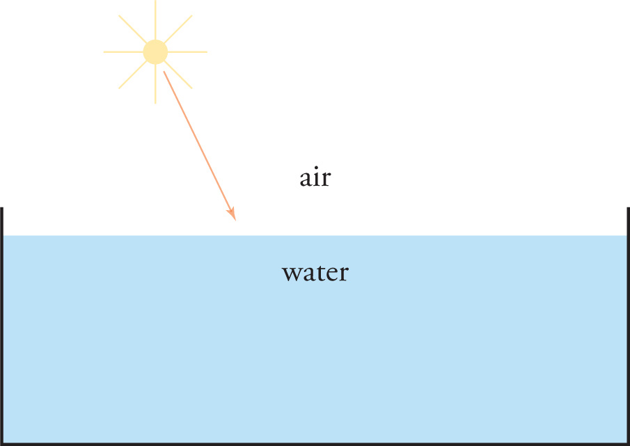
When a beam of light strikes the boundary between two transparent media, some of the light will be reflected from the surface. In the figure below, some of the sunlight will be reflected off the water in the tank.
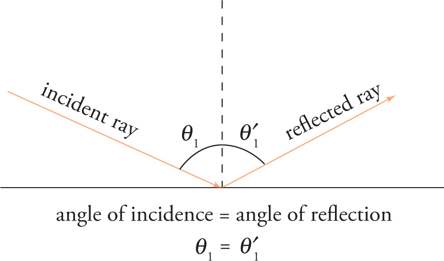
When a ray of light passing through one medium is reflected from the surface of another, the angle at which it bounces off the new medium is equal to the angle at which it strikes. In other words, the angle of reflection is equal to the angle of incidence. This fact is known as the law of reflection. Notice that, by definition, the angles of incidence and reflection are measured with reference to a line that’s perpendicular to the plane of interface between the two media; that is, the angle of incidence and the angle of reflection are the angles that the incident and reflected rays make with the normal, not with the surface.
Example 13-2: In the figure above, assume that a ray of sunlight strikes the water, making an angle of 60° with the surface. What is the angle of reflection?
A. 15°
B. 30°
C. 60°
D. 90°
Solution: Be careful. If the incident ray makes an angle of 60° with the surface, then it makes an angle of 30° with the normal. Therefore, the angle of incidence is 30°. By the law of reflection, the angle of reflection is 30° also. Choice B is the answer.
In the figure below, not all of the sunlight that encounters the surface of the water is reflected; some is transmitted into the water. Unless the angle of incidence is 0°, the light will be bent as it enters the water. The bending is called refraction. The angle of refraction is the angle that the transmitted (or refracted) ray makes with the line that’s perpendicular to the plane of interface between the two media.
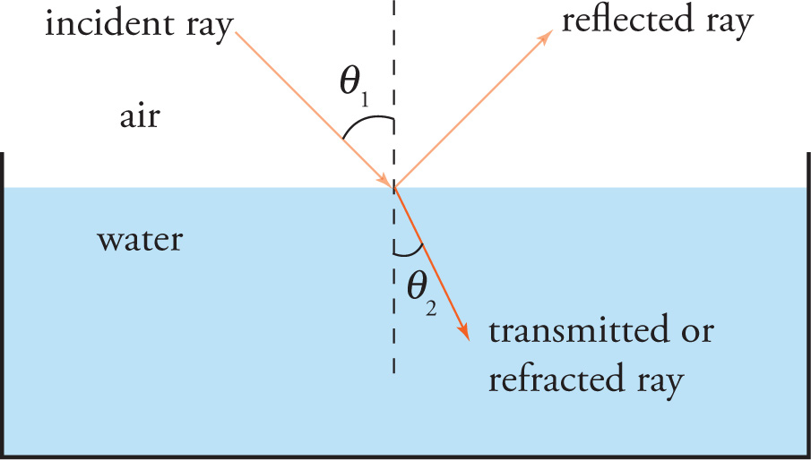
If θ1 = 0° (that is, if the incident ray is perpendicular to the boundary), then θ2 = 0°. However, if θ1 is any other angle, then θ2 will be different from θ1; that is, the ray bends as it’s transmitted. In order to figure out the angle of refraction, we first need to discuss a medium’s index of refraction.
Light travels at speed c = 3×10⁸ m/s when traveling in a vacuum. However, when light travels through a material medium such as water or glass, its transmission speed is less than c. Every medium, in fact, has an index of refraction that tells us how much slower light travels through that medium than through empty space.
Index of Refraction
index of refraction = 
n = 
![]()
The index of refraction of vacuum is, by definition, exactly equal to 1. Because the index for air is very close to 1, we simply use n = 1 for air as well. (The MCAT will use this approximation unless otherwise specified.) Notice that n has no units, it’s never less than 1, and the greater the value of n for a medium, the slower light travels through that medium. For most materials, the value of n is between 1 and 2.5. Glass has an index of refraction of about 1.5 (but varies depending on the type of glass) while diamond has a particularly high value of n, about 2.4. Values of n above 2.5 are rare.
Example 13-3: Light travels through water at an approximate speed of 2.25 × 10⁸ m/s. What is the refractive index of water?
A. 0.75
B. 1.33
C. 1.50
D. 2.25
Solution: First, eliminate choice A: The index of refraction is never less than 1. Now, by definition,

Therefore, the answer is B.
Now that we know about the index of refraction, we can state the rule that’s used to figure out the angle of refraction. It’s called the law of refraction, or Snell’s law:
Law of Refraction (Snell’s Law)
n1 sinθ1 = n2 sin θ2
In this equation, n1 is the refractive index of the medium through which the incident ray is traveling, and n2 is the refractive index of the medium through which the transmitted (or refracted) ray is traveling.

It follows from Snell’s law that if n2 > n1, then θ2 < θ1. That is, if the transmitting medium has a higher index of refraction than the incident medium, then the ray will bend toward the normal. Similarly, if n2 > n1, then θ2 < θ1. That is, if the transmitting medium has a lower index of refraction than the incident medium, then the ray will bend away from the normal. You should memorize both of these facts.
Example 13-4: A ray of light traveling through air is incident on a piece of glass whose refractive index is 1.5. If the sine of the angle of incidence is 0.6, what’s the sine of the angle of refraction?
Solution: Using the law of refraction, we find that
n1 sinθ1 = n2 sinθ2 = → (1)(0.6) = (1.5) (sinθ2) → sinθ2= 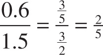 = 0.4
= 0.4
Notice that sinθ2 is less than sinθ1; this immediately tells us that θ2 < θ1. The light is traveling from air (n1 = 1) into glass, whose refractive index is higher. If the transmitting medium (i.e., the second one) has a higher index of refraction than the incident medium (i.e., the first one), then θ2 will be less than θ1; that is, the ray will bend toward the normal.
Example 13-5: Consider the diagram below, showing an incident ray, reflected ray, and transmitted ray:

What information is needed to find θ2?
A. n1, n2, and θ1
B. n1, n2, and θ3
C. n1 only
D. θ1 only
Solution: The angle labeled θ2 is the angle of reflection. To find it, all we need to know is the angle of incidence, θ1. (By the law of reflection, we find that θ2 = θ1.) The answer is D. (This unconventional labeling of the angles is a common MCAT tactic, by the way.)
When a light ray traveling in a medium of high refractive index approaches a medium of lower refractive index (for example, a light ray traveling in water towards the interface with the air), it may or may not escape into the second medium. If the ray’s angle of incidence exceeds a certain critical angle, the light ray will undergo total internal reflection: All of the incident ray’s energy will be reflected back into its original medium; there will be no refracted ray.
Critical Angle for Total Internal Reflection
sinθcrit = 
![]()
In this equation, n1 is the refractive index of the medium through which the incident ray is traveling, and n2 is the refractive index of the medium on the other side of the boundary. The angle θcrit is the critical angle. What this means is that if the angle of incidence, θ1, is greater than θcrit, then total internal reflection will occur.1 However, if θ1 is less than θcrit, then total internal reflection will not occur. (If θ1 just happens to equal θcrit, then the refracted beam skims along the boundary with θ2 = 90°.)
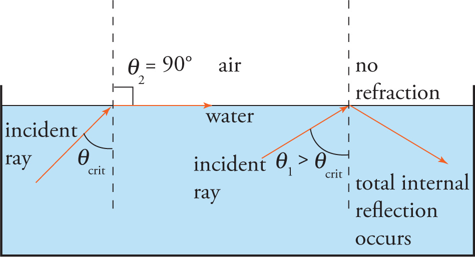
Notice that there can be a critical angle for total internal reflection only if n1 is greater than n2. For example, a beam of light incident in the air and striking the surface of the water can never experience total internal reflection because n1 < n2. In other words, there’ll be some reflection and some refraction, as usual. In this case, some of the light’s intensity will always be transmitted into the water.
Example 13-6: A beam of light is incident on the boundary between air and a piece of glass whose index of refraction is 
![]() . When would total internal reflection (TIR, for short) of this beam occur?
. When would total internal reflection (TIR, for short) of this beam occur?
Solution: First, in order to have TIR, the beam would have to start in the glass, trying to exit into the air. (If the beam were traveling in the air and incident on the glass, then TIR could not occur.) Furthermore, the angle of incidence would have to be greater than the critical angle, which we calculate as follows:
sin θcrit = 
![]() =
= 
![]() =
= 
![]() → θcrit = 45°
→ θcrit = 45°
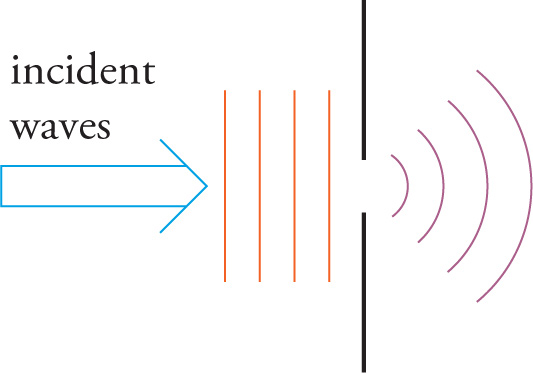
Simply put, waves, whether they’re water waves, sound waves, EM waves, etc., don’t always travel in a single direction when they encounter an obstruction. This redistribution of the wave’s intensity is known as diffraction. Water waves bend around a rock sticking up out of the water, for example. The “obstruction” can even be a hole. For example, water or light incident on a hole in a barrier will pass through and spread out beyond the barrier. These effects are observed when the size of the object or opening is comparable to the wavelength of the waves.
Normally, the electric-field components of the waves in a beam of light vibrate in all planes. Polarized light is light whose direction of polarization has been restricted somehow. For example, all the waves in a beam of plane-polarized light have their electric-field components vibrating in a single plane.
It is possible to transform unpolarized light into polarized light by several methods. One method is the use of a polarizing filter. The filter has a polarization axis, so that when unpolarized light strikes the filter, only the portion of the waves vibrating in that direction pass through while the portion of the waves vibrating perpendicular to the axis is absorbed. The light that emerges is now polarized in in direction of the axis and has half the intensity of the original unpolarized light.
If polarized light passes through a second polarizer, the amount of light that passes through or is absorbed depends on the angle between the direction of polarization of the incident light and the axis of the polarizer. As an example, if vertically polarized light is incident upon a horizontally polarizing filter, none of the light will pass through.
If two light waves of equal amplitude vibrate perpendicular to each other and have a 90° phase difference (the “crest” of one wave interferes with the “0” of the other), the light is circularly polarized.

As a result, the electric field appears to be rotating.
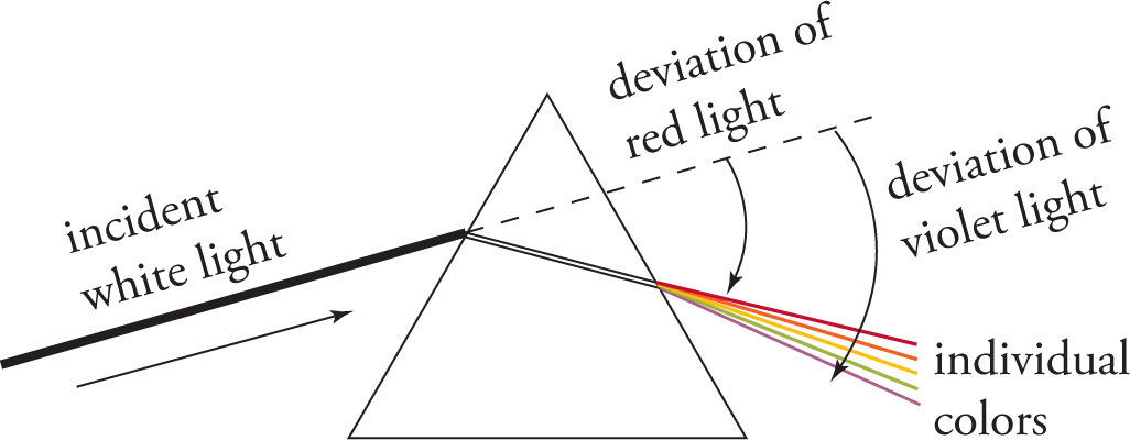
When light moves from one medium to another, some wavelengths are bent more than others. The reason for this is that electromagnetic waves of different frequencies travel at slightly different speeds when traveling through a material medium like glass or water. Although Big Rule 1 for waves states that the speed of a wave is determined by the medium, not by the wave’s frequency, light waves traveling through a material medium are an exception to this rule.2 (In fact, they’re the only exception that’s at all likely to appear on the MCAT.) When light travels through a material (not vacuum), different frequencies will have different speeds. Thus, when we say that the index of refraction for a piece of glass is 1.5, what is really true is that the index varies slightly as the color of the light varies. For example, the index of refraction of the glass could be 1.47 for red light but 1.54 for violet light.3 Because different colors have different refractive indexes, they will have different angles of refraction. This is why when white light passes through a prism, the beam is broken into its component colors. Each color leaves the prism at its own angle of refraction.4 We call this variation in wave speed for different frequencies (and the effects this variation produces) dispersion.
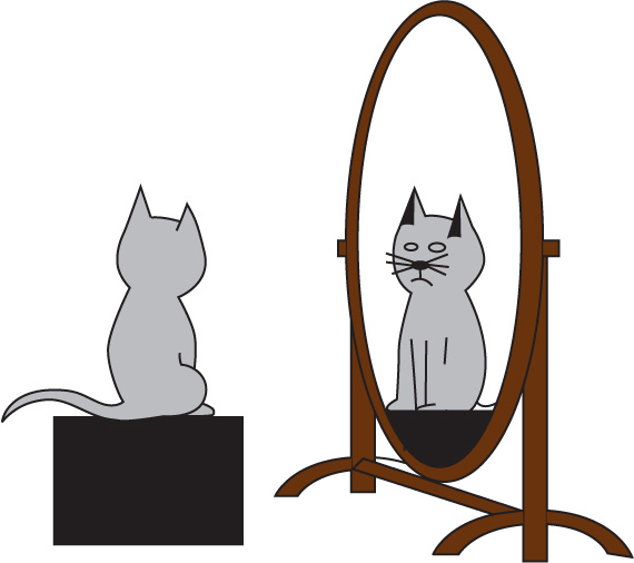
A mirror is a surface, usually made of glass or metal, that forms an image of an object by reflecting light.
A plane mirror is an ordinary flat mirror. If you put an object in front of a plane mirror, the image will appear to be behind the mirror. The image will be the same size as the object and will appear to be as far behind the mirror’s surface as the object is in front of it. The image will also appear upright; it won’t be inverted.
We all have experience with plane mirrors, but a curved mirror presents us with images that are less familiar. The purpose of this section is to find a systematic way to describe the images formed by curved mirrors.
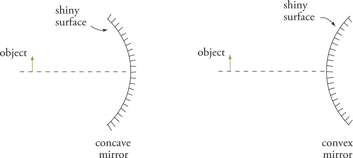
There are essentially two types of curved mirrors: concave and convex. The shiny (reflecting) surface of a concave mirror appears like the entrance to a “cave” from the point of view of the object. The reflecting surface of a convex mirror bends away from the object. As a simple demonstration of the difference, imagine holding a polished spoon. If you look into the spoon, you’re looking at a concave surface; if you turn it around and look at the back of the spoon, you’re looking at a convex surface.
The curved mirrors we’ll consider could be termed spherical mirrors, because near the center of the mirror, the surface is spherical (that is, part of a sphere).
When light parallel to the central axis of a concave mirror strikes the surface, it’s reflected through a point called the focus (or focal point), denoted by F. This point is halfway to the center of curvature, C, of the mirror, which is the center of the sphere that the mirror is “cut from.” The distance between the center of curvature and the mirror is called the radius of curvature, r. (The radius of curvature is also sometimes denoted by RC.) Because the focal point is halfway between the mirror and C, the distance from the mirror to the focal point, the all-important focal length, f, is half the radius of curvature: f = 
![]() r.
r.
When light parallel to the central axis of a convex mirror strikes the surface, it’s reflected directly away from the “imaginary” focal point behind the mirror.
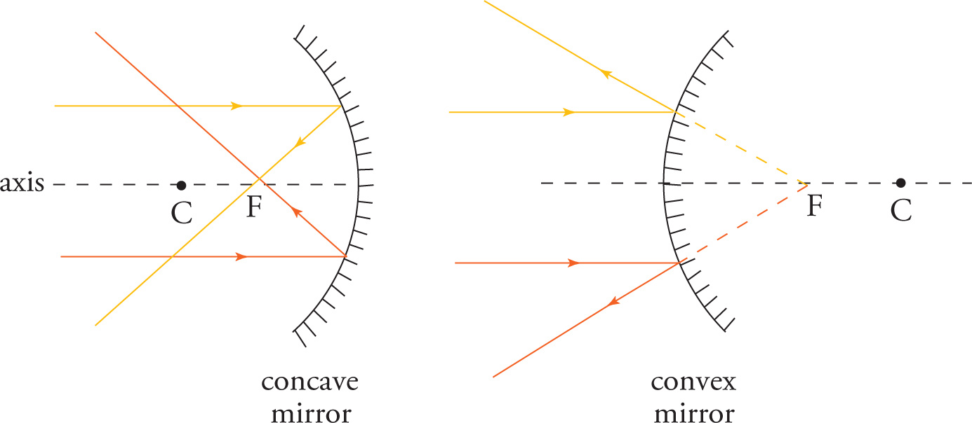
We see an image in a mirror at the point where the rays reflected off the mirror intersect or at the point from where the reflected rays seem to intersect (and therefore emanate from) behind the mirror. When a very distant object is placed in front of a mirror, the light rays that strike the mirror are approximately parallel, like the rays shown above. This illustrates the significance of the focal point. The image of a distant object will appear at the focal point, for all curved mirrors. This turns out to be true for thin lenses as well. But what if the object is not distant?
The following figures illustrate the process of image formation by curved mirrors:
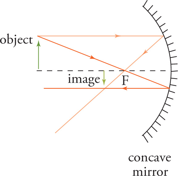
The ray diagram for the concave mirror shows two incident rays reflecting off the mirror. One ray, parallel to the axis, is reflected through the focal point. Another ray, which goes through the focal point, is reflected parallel to the axis. The intersection point of these reflected rays determines the location of the image.
Note that the light rays still cross after reflecting off the mirror, but the image is located behind the focal point. If the object is moved closer to the mirror (i.e., inside the focal point), the reflected rays no longer cross and the image forms behind the mirror.

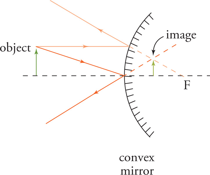
One ray, parallel to the axis, is again reflected through the focal point. Another ray, which is directed as if it came from the focal point, is reflected parallel to the axis.
The ray diagram for the convex mirror also shows two incident rays reflecting off the mirror. One ray, parallel to the axis, is reflected directly away from the focal point. Another ray, which hits the center of the mirror (the point where its axis of symmetry intersects the mirror surface), is reflected at the same angle below the axis. Following these reflected rays back behind the mirror, their intersection point determines the location of the image.
Ray diagrams (like the ones drawn in the figures above) can be used to determine the approximate location of the image, but they usually can’t give precise answers to all the questions we may be asked about the image formed by a mirror. What we want is a systematic way to get precise answers to these four questions:
1. Where is the image?
2. Is the image real or is it virtual?
3. Is the image upright or is it inverted?
4. How tall is the image (compared to the object)?
Before we discuss how to answer these questions, let’s first define the terms real and virtual. An image is said to be real if light rays actually focus at the position of the image. A real image can be projected onto a surface. An image is said to be virtual if lights rays don’t actually focus at the apparent location of the image. For example, look back at the previous figures, showing the formation of images by a concave mirror and by a convex mirror. The image formed by the concave mirror in the first diagram is real: light rays actually intersect at the image location. However, the images formed by the concave mirror in the second diagram and by the convex mirror are virtual: no light rays intersect at its location, they just seem to come from that location.
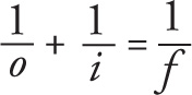
To answer the first two questions given above, we use the mirror (and lens) equation:
Mirror (and Lens) Equation

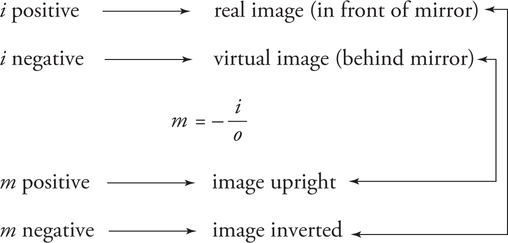
Here, o stands for the object’s distance from the mirror, and is always positive. The value of f represents the focal length of the mirror. The value of i that satisfies this equation gives us the image’s distance from the mirror. Both f and i are positive if they are on the same side as the human observer in relation to the mirror or lens. In the case of a mirror, the human observer is on the same side as the object. In the case of a lens, the human observer is on the opposite side of the object. Using the mirror (and lens) equation, we can find the location of the image, answering the first question.
The second question is also answered using the mirror equation. If we get a positive value for i, that tells us that the image is in front of the mirror and it’s real; a negative value for i means the image is behind the mirror and is virtual. For example, let’s say that o = 2 cm and f = 6 cm. Substituting these values into the mirror equation, we find that i = −3 cm. Therefore, the image is 3 cm behind the mirror and it’s virtual. Note that you can use any unit for the measurement of distance, as long as it is the same unit for o, i, and f.
To answer the last two questions, we then use the magnification equation:
Magnification Equation
m = −
![]()
The value of m is the magnification factor; multiplying the height of the object by m gives us the height of the image. The sign of m tells us whether the image is upright or inverted. If m is positive, the image is upright; if m is negative, the image is inverted. To illustrate this, let’s continue our example above, with o = 2 cm and f = 6 cm. We found that i = −3 cm. Therefore, the magnification factor is m = −(−3 cm)/(2 cm) = +1.5. This tells us that the height of the image is 1.5 times the height of the object, and (because m is positive) the image is upright.
The object distance, o, is always positive. If i is positive, then m is negative; if i is negative, then m is positive. In other words,
Real images are inverted, and virtual images are upright.
Now, the only thing that’s left to do is to find the way to “tell” the mirror equation whether we have a concave mirror or a convex mirror. The rule is simple: When using the mirror equation, we write the focal length of a concave mirror as a positive number, and we write the focal length of a convex mirror as a negative number. Here’s a summary of mirrors:
| Concave mirror | Convex mirror |
| f is positive | f is negative |

![]()
• Concave mirrors can create real and virtual images
• Convex mirrors can only create virtual images
Example 13-7: Describe the image formed in a plane mirror.
A. Real and upright
B. Real and inverted
C. Virtual and upright
D. Virtual and inverted
Solution: First, eliminate choices A and D; real always goes with inverted, and virtual always goes with upright. We know from common experience that the image formed in a flat mirror is upright, so the answer must be C.
Example 13-8: If an object is placed very far from a concave mirror, where will the image be formed?
A. Halfway between the focal point and the mirror
B. At the focal point
C. At the center of curvature
D. At infinity
Solution: Use the mirror equation. “The object is placed very far from a mirror” means that we take o = ∞, so 1/o = 0. The mirror equation then says 1/i = 1/f, so i = f. That is, the image is formed at the focal point of the mirror, choice B.
Example 13-9: An object is placed 40 cm in front of a concave mirror with a radius of curvature of 60 cm. Locate and describe the image.
Solution: Because f = ![]() r, we know that f = 30 cm. The mirror equation now gives
r, we know that f = 30 cm. The mirror equation now gives

(Be careful: The MCAT often gives the radius of curvature, r. What you want is f, the focal length, which is half of r.) Since i is positive, we know the image is real; also, it’s located 120 cm from the mirror on the same side of the mirror as the object. (Virtual images are located behind the mirror.) Since m = −i/o = −(120 cm)/(40 cm) = −3, we know that the image is 3 times the height of the object and inverted.
Example 13-10: An object is placed 40 cm in front of a convex mirror with a radius of curvature of −60 cm. Locate and describe the image.
Solution: Because f = ![]() r, we know that f = −30 cm. The mirror equation now gives
r, we know that f = −30 cm. The mirror equation now gives

Since i is negative, we know the image is virtual; also, it’s located 120/7 ≈ 17 cm from the mirror on the opposite side of the mirror from the object. Since m = − i/o = −(−
![]() cm)/(40 m) = +3/7, we know that the image is 3/7 times the height of the object and upright. Comparing this example to the preceding one, notice how critical the sign of f was. It changed everything about the image.
cm)/(40 m) = +3/7, we know that the image is 3/7 times the height of the object and upright. Comparing this example to the preceding one, notice how critical the sign of f was. It changed everything about the image.
Example 13-11: A convex mirror forms an upright image 12 cm behind the mirror when an object of height 15 cm is placed 20 cm in front of it. What is the height of the image?
Solution: To find the height of the image, we need the magnification. We’re given that o = 20 cm and i = −12 cm. (We know that i is negative because not only do convex mirrors only form virtual images [a good fact to remember, by the way] but the question also says that the image is formed “behind the mirror.” Images formed behind the mirror are virtual.) Therefore, m = − i/o = −(−12 cm)/(20 cm) = 3/5. Multiplying the height of the object by the magnification gives the height of the image. Therefore, the height of the image is (3/5)(15 cm) = 9 cm.
A lens is a thin piece of clear glass or plastic that forms an image of an object by refracting light. The purpose of this section is to find a systematic way to describe the images formed by lenses.
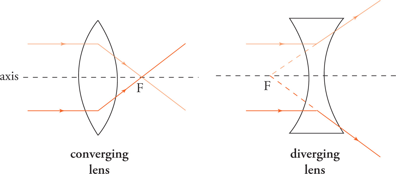
There are essentially two types of lenses: converging and diverging. Converging lenses are thicker in the middle than they are at the ends, and they refract light rays that are parallel to the axis toward the focal point on the other side of the lens. Diverging lenses are thinner in the middle than they are at the ends, and they refract light rays that are parallel to the axis away from the “imaginary” focal point that’s in front of the lens.
We want to be able to answer the same four questions for lenses as we did for mirrors. Fortunately, virtually everything we did for mirrors carries over unchanged to lenses. For example, the mirror equation is also the lens equation, and the magnification equation is also the same. The conventions for positive and negative i and m are also the same for lenses as they are for mirrors.
We distinguish between the two types of lenses in the same way we distinguished between the two types of mirrors. When using the lens equation, we write the focal length of a converging lens as a positive number, and we write the focal length of a diverging lens as a negative number.
Here’s an important note. The MCAT uses the terms concave and convex to refer to different mirrors and lenses. The diagrams above show us that the surfaces of a converging lens are convex, and the surfaces of a diverging lens are concave. Thus, a concave lens is the same as a diverging lens, and a convex lens is the same as a converging lens. Now for a warning: For a concave mirror, f is positive; and for a convex mirror, f is negative. When these terms are applied to lenses, things necessarily switch: For a concave lens, f is negative; and for a convex lens, f is positive. Be careful when you see the words concave or convex. Whether these terms describe a mirror or a lens will make a critically important difference in whether you write the focal length as a positive or as a negative number.
Besides the fact the lenses form images by refracting light (rather than by reflecting light, as is the case for mirrors), there’s really only one difference: For lenses, real images are formed on the opposite side of the lens from the object while virtual images are formed on the same side of the lens as the object.
Lenses
| Converging lens | Diverging lens |
| (convex lens) | (concave lens) |
| f is positive | f is negative |
![]()
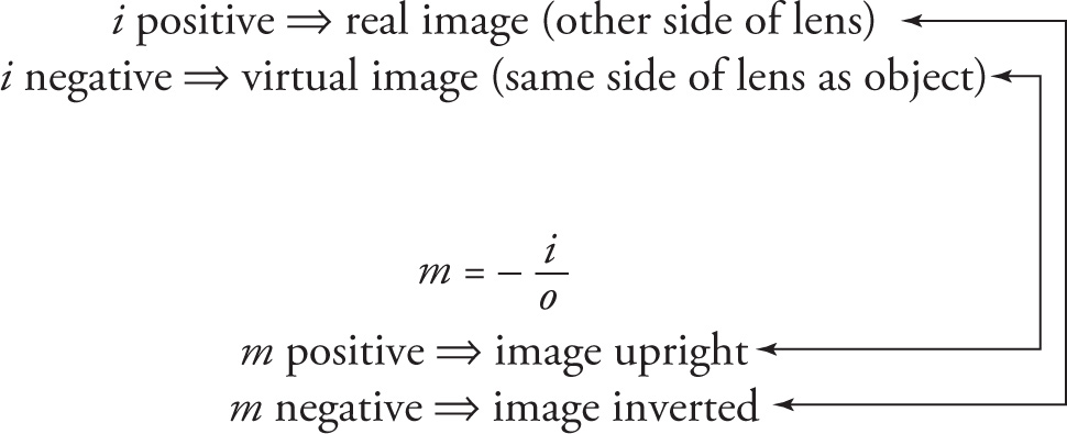
• Converging (convex) lenses can create real and virtual images.
• Diverging (concave) lenses can create only virtual images.
Example 13-12: An object is placed 10 cm in front of a diverging lens with a focal length of −40 cm, then the image will be located:
A. 5 cm in front of the lens
B. 5 cm behind the lens
C. 8 cm in front of the lens
D. 8 cm behind the lens
Solution: We use the lens equation to find i:

This eliminates choices A and B. Because i is negative, the image is virtual, and for lenses, virtual images are formed on the same side of the lens as the object. Therefore, the answer is C.
Example 13-13: An object of height 10 cm is held 50 cm in front of a convex lens with a focal length of magnitude 40 cm. Describe the image.
Solution: The fact that the lens is convex means that it’s a converging lens with a positive focal length; therefore, f = +40 cm. The lens equation now gives us i:

Because i is positive, we know the image is real; also, it’s located 200 cm from the lens on the opposite side of the lens from the object. Because m = −i/o = −(200 cm)/(50 cm) = −4, we know that the image is 4 times the height of the object and inverted.
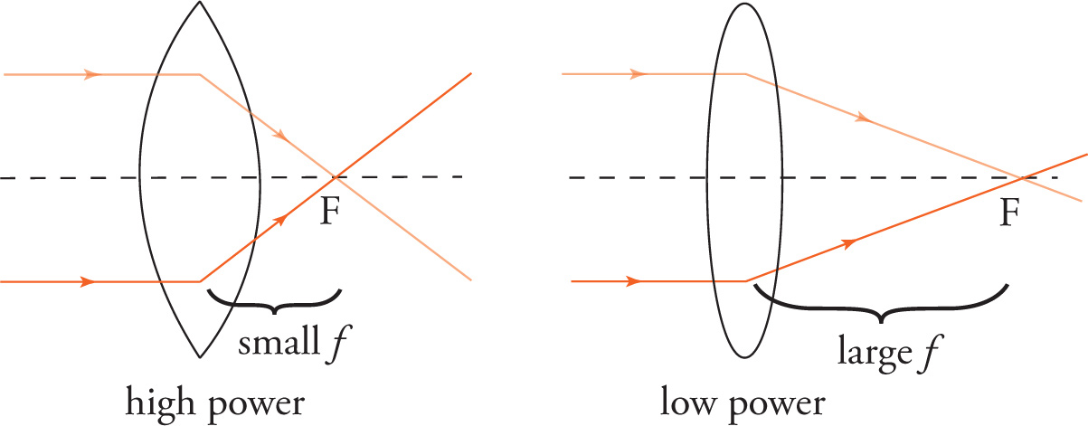
A lens with a short focal length refracts light more (i.e., through larger angles) than a lens with a longer focal length. We say that the lens of short focal length has a greater power than a lens with a longer focal length.
The power of a lens is defined to be the reciprocal of f, the focal length. When f is expressed in meters, the unit of lens power is called the diopter (abbreviated D).
Lens Power
P = 
![]() where f is in meters
where f is in meters
For example, to find the power of a lens whose focal length is 40 cm, we first write f in meters: f = 0.4 m. Since 0.4 = 2/5, the reciprocal of 0.4 is 5/2 = 2.5. Therefore, the power of this lens is 2.5 diopters. Since the focal length of a converging lens is positive, the power of a converging lens is positive. Similarly, since the focal length of a diverging lens is negative, the power of a diverging lens is negative.
If two (or more) lenses are placed side by side, the power of the lens combination is equal to the sum of the powers of the individual lenses. In the case of two lenses, P = P1+P2. For example, if we place a converging lens with a power of 3 D right next to a converging lens with a power of 1 D, then the power of the lens combination will be 4 D.
Example 13-14: A lens has a focal length of −20 cm. Is the lens converging or diverging? What is the power of this lens?
Solution: The fact that the lens has a negative focal length means that it’s a diverging (or concave) lens. Rewriting f in meters, we have f = −
![]() m. Therefore, the power of this lens is
m. Therefore, the power of this lens is
P = 
![]() =
=  = −5 D
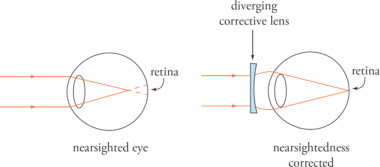
Let’s now look at the fundamental use of auxiliary lenses to correct the two most common types of eye defects: myopia and hyperopia. Myopia is the technical name for nearsightedness; myopic individuals cannot focus clearly on distant objects. Hyperopia (or hypermetropia) is the technical name for farsightedness; in contrast to myopes, hyperopic individuals cannot focus clearly on objects that are near the eye. (As we age, most of us will be afflicted with presbyopia, in which the eyes’ ability to accommodate is compromised by the loss of elasticity in the lens of the eye. Accommodation refers to the ability to focus on nearby objects through the action of the ciliary muscles, which essentially squeeze the lens of the eye, increasing its curvature and decreasing its focal length. However, the correction for presbyopia is the same as that for hyperopia.)
Correcting Myopia: Light rays from objects whose distance from the eye is greater than about 6 m are essentially parallel to the axis of the lens of the eye, so a relaxed eye will focus these rays at the focal point. Because the diameter of a myopic eye is greater than the focal length of the lens of the eye, the image of the object is focused not on the retina but in front of it. As a result, a myopic individual receives a blurred image of distant objects. To correct this defect, a lens that “delays” the focusing is required. In essence, what is needed is a lens to diverge the parallel rays before they enter the lens of the eye so that they will focus beyond the focal point of the unaided eye, specifically on the retina. Because diverging lenses have negative focal lengths, they have negative powers (this follows from the definition P = 1/f). The greater the distance between the focal point of the lens of the myopic eye and the retina, the more the auxiliary lens must diverge the incoming parallel rays; that is, the more powerful the corrective lens (and the more negative the lens power).
Correcting Hyperopia or Presbyopia: In these cases, light rays would be focused beyond the retina, either due to the diameter of the eye being smaller than the focal length of the lens of the eye or the inability of the ciliary muscles to decrease the focal length of the lens of the eye. To correct this defect, a lens that “accelerates” the focusing is required. In essence, what is needed is a lens to converge the rays before they enter the lens of the eye so that they will focus in front of the focal point of the unaided eye, specifically, on the retina. Because converging lenses have positive focal lengths, they have positive powers. (This follows from the definition P = 1/f.) The greater the distance between the focal point of the lens of the hyperopic eye and the retina, the more the auxiliary lens must converge the incoming rays, that is, the more powerful the corrective lens (and the more positive the lens power).
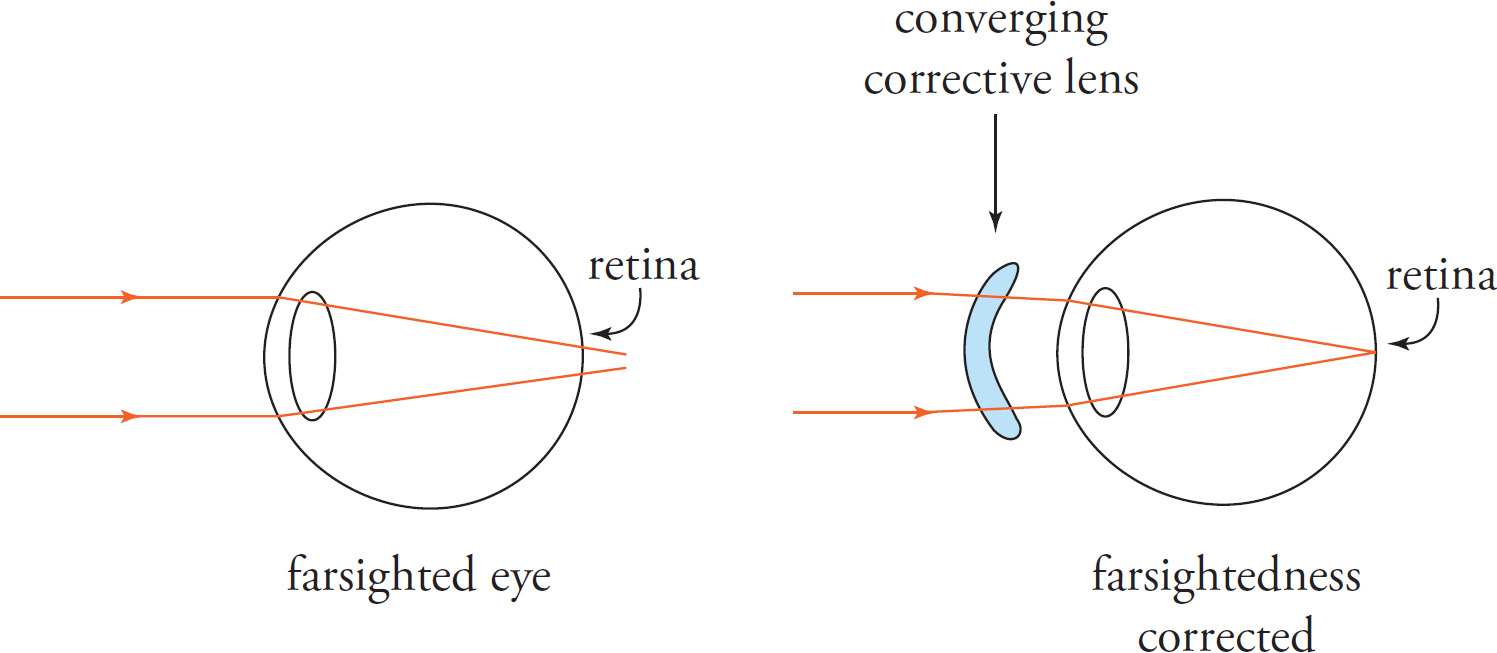
If you wear eyeglasses or contacts, check the prescription. If you have trouble seeing faraway objects, then you’re nearsighted (myopic), and your corrective lenses are diverging and will have a negative power. On the other hand, if you have trouble seeing objects that are close-up, then you’re farsighted (hyperopic), and your corrective lenses are converging and will have a positive power. Also, if the power of your left corrective lens is different from the power of your right corrective lens, the lens with the power of greater magnitude corresponds to the weaker eye. For example, if your left eye requires a lens of power −3.5 D while your right eye requires a lens of power −3.25 D, then your left eye is weaker because 3.5 > 3.25.
Light acts as both a wave and a particle depending on the circumstance. In the former, energy is a function of amplitude; in the latter, energy is a function of frequency.
c = 3 × 10⁸ m/s for light in a vacuum
– All angles for reflection and refraction formulas are measured from the normal to the surface.
Photon energy: E = hf = h
![]()
Law of reflection: θ1 = θ′1
Index of refraction: n = 
![]() , n≥1
, n≥1
Law of refraction (Snell’s law): n1 sinθ1 = n2 sinθ2
Total internal reflection: If n1 > n2 and θ1 > θcrit, where sinθcrit = 
![]()
Total internal reflection (meaning no light is transmitted from the incident medium through the boundary) can occur for incident angles greater than θcrit and only when the incident medium has a larger index of refraction (n) than that of the medium beyond the boundary.
Mirror/lens equation: 
Magnification: m = −
![]()
Converging mirror or lens (concave mirror or convex lens) ↔ f positive
Diverging mirror or lens (convex mirror or concave lens) ↔ f negative
Note o is always positive.
Real, inverted image ↔ positive i
Virtual, upright image ↔ negative i
Lens power: P = 
![]() (P in diopters when f is expressed in meters)
(P in diopters when f is expressed in meters)
1. In optics, spontaneous parametric down conversion is often used to create two photons from one photon. Thus, it is possible for a blue photon with a frequency of 700 THz to be split into two identical red photons when incident on a nonlinear crystal. What is the wavelength of the red photons with respect to the blue photon, λB, given that energy is conserved?
A) 2λB
B) 4λB
C) 1/2λB
D) 1/4λB
2. If the magnification of a mirror is 2, where are the focal point and the image?
A) The image is on the same side of the mirror as the object and the focal point is twice as far from the mirror as the object.
B) The image is on the same side of the mirror as the object and the focal point is half as far from the mirror as the object.
C) The image is on the opposite side of the mirror as the object and the focal point is twice as far from the mirror as the object.
D) The image is on the opposite side of the mirror as the object and the focal point is half as far from the mirror as the object.
3. Glasses that correct for nearsightedness have a negative power associated with them. Are these lenses diverging or converging, and do they have a focal length that is positive or negative?
A) Diverging lens with positive focal length
B) Converging lens with negative focal length
C) Diverging lens with negative focal length
D) Converging lens with positive focal length
4. A physics student looking into a carnival funhouse mirror sees that his image is upright but his head appears twice as big as normal and his feet look half as big as normal. Let o represent the distance from the student to the mirror, ftop represent the focal length of the top of the mirror (where the student’s head appears), and fbottom represent the focal length of the bottom of the mirror (where the student’s feet appear). What combination of curved mirrors is necessary to create the illusion?
A) The mirror top is concave with ftop = 2o and the mirror bottom is convex with fbottom = −(1/2)o.
B) The mirror top is concave with ftop = 2o and the mirror bottom is convex with fbottom = −o.
C) The mirror top is concave with ftop = 3o and the mirror bottom is convex with fbottom = − (1/3)o.
D) The mirror top is convex with ftop = −o and the mirror bottom is concave with fbottom = (1/2)o.
5. For a plane mirror, the object distance from the mirror is o, the image distance from the mirror is i, the focal point distance from the mirror is f, and the magnification of the mirror is m. Which of the following is true of the plane mirror?
I. Since f approaches infinity, then i = −o.
II. Since f = 0, then i = −o.
III. Since i = −o, then m = 1 and the image is the same size as the object.
A) I only
B) II only
C) I and III
D) II and III
6. An object is placed in front of a convex mirror. If the object is moved closer to the mirror, the image will move:
A) farther from the mirror and become smaller.
B) farther from the mirror and become larger.
C) closer to the mirror and become smaller.
D) closer to the mirror and become larger.
7. A beam of light passing through crown glass (n = 1.5) strikes the surface between the glass and air and experiences Total Internal Reflection. Which of the following changes to the experiment would ensure that the beam of light continues to experience this phenomenon?
A) Have the light originate in air
B) Decrease the angle of incidence
C) Immerse the glass in water (n = 1.33)
D) Decrease the wavelength of light
Optical instruments, such as mirrors and lenses, are often used to converge or diverge light. When more than one optical instrument bends light in succession, it is sometimes useful to consider the image produced by the first mirror or lens to be the object from which the light comes to the second mirror or lens. In such cases, the virtual object for the second instrument is sometimes on the opposite side of the instrument as the incoming light. The convention for these objects is that their distances are negative in optics equations.
One example of the use of multiple optical instruments together can be found in vision correction. For an object to appear in focus, light from that object must converge on the retina at the back of the eye, roughly 2 cm away from the front in most humans. Normally, the cornea and crystalline lens (together effectively constituting one converging lens, with an index of refraction of about 1.4) at the front of the eyeball do this. When this does not occur, eyeglasses can often be used to fix the problem. Eyeglasses are made of converging or diverging lenses in frames, and they change the angle of the incoming light that reaches the lens at the front of the eye, which then is able to focus the differently angled light at the retina.
A lens bends light by refraction, so the refractive index of the lens material is one of the determinants of the focal length of the lens. For a lens with circular curvatures on either side, the radius of curvature of each side is another determinant. In a vacuum or air, the thin lens equation gives the focal length of a lens of minimal thickness, index of refraction n, radius of curvature of the side nearest the source of light R1, and radius of curvature of the side opposite the source of light R2:
![]() = (n−1)(
= (n−1)(
![]() −
− 
![]() )
)
Equation 1
1. If a certain eye can only focus on objects at least 50 cm away, which of the following lenses, if placed in front of the eye, would allow it to focus on an object 25 cm away?
A) A converging lens with focal length 17 cm
B) A diverging lens with focal length 17 cm
C) A diverging lens with focal length 50 cm
D) A converging lens with focal length 50 cm
2. Which of the following is true of a nearsighted eye’s native lens?
A) Its lens power is too small, causing the light rays to converge before they reach the retina.
B) Its lens power is too small, causing the light rays not to have converged even when they reach the retina.
C) Its lens power is too great, causing the light rays to converge before they reach the retina.
D) Its lens power is too great, causing the light rays not to have converged even when they reach the retina.
3. Which of the following describes the image formed in a typical human eye from light rays from an object 10 cm away?
A) The image is virtual and 0.4 cm away from the lens.
B) The image is real and 2 cm away from the lens.
C) The image is real and 2.5 cm away from the lens.
D) The image is virtual and 2.5 cm away from the lens.
4. Which of the following is true of images created with optical instruments by virtual objects with negative object distances?
A) Real images are always upright, and virtual images are always inverted.
B) Real images are always inverted, and virtual images are always upright.
C) Both real and virtual images are always upright.
D) Both real and virtual images are always inverted.
5. What is the speed of light in the lens of the eye?
A) 1.50 × 10⁸ m/s
B) 2.14 × 10⁸ m/s
C) 3.00 × 10⁸ m/s
D) 4.20 × 10⁸ m/s
6. A person notices that an object at a given distance is clearly in focus when viewed in air, but when the same object at the same distance is viewed in clear water, it appears blurry. Which of the following best explains this phenomenon?
A) The water absorbs much of the light energy coming from the object.
B) The index of refraction of water is different from that of air.
C) Dispersion in the water causes only a few of the light rays from the object to reach the eyes.
D) The water acts as a polarizing filter.
7. How will the lens power of a thin lens with a greater index of refraction compare to that of a thin lens with a smaller index of refraction, if the two lenses have all the same radii of curvatures?
A) It will be greater.
B) It will be equal.
C) It will be less.
D) It cannot be determined.
1. A The energy of a photon is E = hf = hc/λ. Since EB = 2ER we know that fB = 2fR, and consequently, λR = 2λB.
2. C The magnification equation is m = −i/o. Since m = 2, i is negative, which tells us the image is on the opposite side of the mirror as the object, a virtual image. This question is a two-by-two, meaning that we need two pieces of information to answer correctly. The fact that the image is virtual eliminates choices A and B. Using the mirror equation we find that f = 2o. Therefore, the focal point is twice as far from the mirror as the object.
3. C For lenses, negative focal length is a property of a diverging lens and a positive focal length is a property of a converging lens. This eliminates choices A and B. The second piece of information comes from the fact that the power of nearsighted corrective glasses is negative, indicating a negative focal length since P = 1/f.
4. B Since the image is always upright, the magnification, m, is always positive. For the top of the mirror, m = 2 = −i/o and i = −2o. Plugging this into the mirror equation 1/f = 1/i + 1/o = 1/(−2o) + 1/o = 1/(2o) and f = 2o. A positive focal length corresponds to a concave mirror. For the bottom of the mirror, m = 1/2 and i = − (1/2)o. Plugging this into the mirror equation 1/f = 1/i + 1/o = −2/o + 1/o = −1/o and f = −o. A negative focal length corresponds to a convex mirror. The correct answer is choice B.
5. C For a plane mirror, the image size is the same as the object size, and the object is upright. So m = −i/o = 1 and i = −o. So Item III is true, eliminating choices A and B. Both Items I and II have i = −o, so plugging this into the mirror equation gives 1/f = 1/i + 1/o = 1/(−o) + 1/o = 0 and f = something very large. So Item I is true, eliminating choice D. Notice that Item II cannot be true because if f = 0 then 1/f = 1/0 which is not defined. The correct answer is choice C.
6. D Ray tracing is not necessary to solve this problem. The mirror and the magnification equations can be used, but without numbers they could be time consuming. A simple method would be to choose the initial object distance to be very large (o ≈ ∞). For any mirror (except the plane mirror) or lens, the image of a distant object forms at the focal point (Note: the mirror equation, 1/o + 1/i = 1/f, backs this up; for large o, 1/o ≈ 0, so i ≈ f). It also stands to reason that the image of a very distant object will be very small (by the magnification equation, m = −i /o ≈ 0). The final object distance can be chosen as almost 0 (i.e., when the object is pressed up against the mirror. From experience, if an object is pressed up against any mirror, the image will also be pressing up against the mirror and appear to be the same size as the object. The image therefore moves from the focal point to the mirror, eliminating choices A and B, and goes from being very small to the size of the object, eliminating choice C.
7. D For light to experience total internal reflection, two conditions must be met. First, the light must originate in the slower medium (i.e., the one with the larger index of refraction), which eliminates choice A; second, the angle of incidence must be greater than the critical angle. While decreasing the angle of incidence may result in total internal reflection, it is not guaranteed since the angle could be smaller than or equal to the critical angle. This eliminates choice B. The formula for the critical angle is given by θc = sin−1 (n2 / n1). Immersing the glass in water would increase n2, which would increase the critical angle. This may cause the angle of incidence to be less than the critical angle, eliminating choice C. Due to dispersion, the shorter the wavelength of light, the slower it travels in glass, and therefore the more it will bend. Another way of thinking about this is that n1 slightly increases for shorter wavelength. This would decrease the critical angle, and therefore make it impossible for refraction to occur.
1. D According to the first paragraph, the lens needs to create an image where the object ought to be (50 cm away from the eye), and then the image becomes the “object” for the eye’s lens, which converges the light on the retina. In other words, the object is at a distance of 25 cm and the image at a distance of 50 cm, and since the image is going to be on the same side of the lens as the object, the image will be virtual. Next, apply ![]() =
= 
![]() +
+ 
![]() and plug in:
and plug in: ![]() =
= 
![]() +
+  =
= 
![]() , so the focal length is 50 cm.
, so the focal length is 50 cm.
2. C In this question, one can eliminate two answers by deciding whether the lens power is too great or too small and eliminate the final wrong answer by determining whether the light rays converge too soon or too late. Nearsighted eyes can see near things well (the light of which is already diverging), but cannot focus on faraway things (the light of which is arriving in parallel rays). This suggests that the eyes converge too strongly, which is a too-great lens power (eliminate choices A and B). Second, if the lens converges too strongly, the light rays must converge before they reach the retina (eliminate choice D). Note: This question can be answered without any information from the passage.
3. B According to the second paragraph, the retina is about 2 cm away from the lens in most humans. Also, the light rays actually converge on the retina. That describes the formation of a real image. Thus, the image is real (eliminate choices A and D) and is about 2 cm away from the lens (eliminate choice C). Be careful not to select choice C! This would be the correct answer if the distance between the retina and the lens were the focal length, but this does not match the passage’s description; the position of the light rays actually converging (or where they would be traced back to converge, for a virtual image) is the image distance, not the focal length.
4. A Recall m = −
![]() . If o is negative, then its negative sign cancels with the negative sign already in the equation, and the sign of m matches the sign of i: a positive i implies a positive m, and a negative i implies a negative m. Thus, real images (positive i) are upright (positive m), and virtual images (negative i) are inverted (negative m). Choice B is normally true on the MCAT, but that is because the object distance is normally positive.
. If o is negative, then its negative sign cancels with the negative sign already in the equation, and the sign of m matches the sign of i: a positive i implies a positive m, and a negative i implies a negative m. Thus, real images (positive i) are upright (positive m), and virtual images (negative i) are inverted (negative m). Choice B is normally true on the MCAT, but that is because the object distance is normally positive.
5. B Apply n = 
![]() . According to the second paragraph, in the lens, the index of refraction is 1.4, so v =
. According to the second paragraph, in the lens, the index of refraction is 1.4, so v = 
![]() ≈
≈  ≈ 2.14 × 10⁸ m/s. Note that light cannot travel faster than c, so choice D can be eliminated immediately.
6. B The lens in the eye works by refraction (like all lenses). If the eye does not change, but the medium from which the light is coming changes, then the angle of refraction will change (as in n1 sin θ1 = n2 sin θ1: modify n2 while holding n1 and θ1 constant, and θ2 will change). If the angle of refraction changes, then the light will not focus on the retina anymore. Note: This could be determined without reference to the passage, but if necessary, the fact that the light must converge on the retina can be found in the second paragraph, and the fact that refraction is involved is in the third paragraph. Alternatively, use process of elimination. Even if choice A were true, it would mean that less light energy would reach the eye, reducing the intensity of light; that dims the image but does not blur it. In choice C, dispersion refers to differences in a material’s index of refraction for different frequencies of light (different colors); this might make a rainbow, but it won’t blur the object. In choice D, polarization does not blur light, and water does not normally polarize light.
7. A Recall that lens power is given by P = ![]() , and combining this with Equation 1 yields P = (n − 1)(
, and combining this with Equation 1 yields P = (n − 1)(![]() −
− ![]() ). Thus, P is directly proportional to (n − 1), and when n increases, so does P.
). Thus, P is directly proportional to (n − 1), and when n increases, so does P.
1 If you forget the formula for the critical angle, there’s another way to know that total internal reflection occurs: If you plug numbers into the law of refraction and find that sin θ > 1 (which is impossible), that tells you there is no angle of refraction, so there must be total internal reflection.
2 This isn’t the case when electromagnetic waves travel through vacuum, where all frequencies travel at the same speed, c.
3 In general, as in this example, the higher the frequency of the light, the lower the speed. However, there are complicated exceptions to this rule of thumb, and there’s no need to memorize it or learn about the exceptions for the MCAT.
4 The greater the index of refraction, the more the light will be bent on entering the medium from air or vacuum, so high-frequency violet light will generally bend more than red light.