Chapter 7
Modelling Software Properties
In the previous chapter we considered how a software application might be structured, using very abstract levels of description. This is because, at the architectural level, the design models we create are largely concerned with describing how an application is to be organised as a set of major components.
In this chapter we look at how the attributes of software can be modelled at a more detailed level, although it is still very much an exercise in design abstraction. In particular, we concern ourselves with identifying the different characteristics of software that we want to describe, because at this level of abstraction we need to think about many different aspects of software.
We begin by examining the issue of what a model is, then consider some of the practicalities involved in developing a model. The rest of this chapter is then largely concerned with what properties and attributes we need to model and some ideas about how these can be described.
7.1What is a design model?
In Chapter 2 we introduced the idea of the design model as some form of abstract description for our ideas about how to ‘solve’ some sort of (ill-structured) problem. The idea of using a model of the intended product to explore (and record) design ideas is an old one, and was probably necessitated as the complexity of the final product increased. Pharaoh's pyramid designers may not necessarily have needed to produce models, but certainly by the seventeenth century AD the form of such artifacts as sailing ships had become sufficiently complex to warrant the production of quite elaborate and detailed models that could be used to indicate what the shipwrights were expected to create.
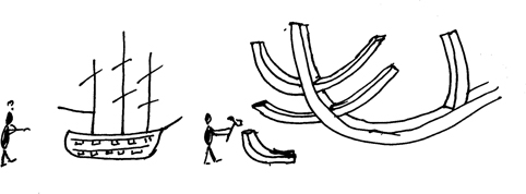
Using a model to guide construction
Software development makes use of a number of different forms of model, not just design models. Modelling is often used to help explore and clarify the requirements for an application. Requirements models are usually very abstract, related to the problem rather than the solution, and in some ways play the same role as the models that architects produce to show how their buildings will look and how they will fit into the landscape. We might also use models to help with such tasks as assessing risk in the development process, and of course, it is often necessary to use cost models to help with planning and managing actual development.
All of these are inter-related of course. A requirements model sets out much of the context and goals for a design model; and the design model provides some of the context required for any modelling of risk or cost. However, for this chapter we will focus on design models—while recognising that they influence, and are influenced by, other models.
Models of physical artifacts tend to have two (related) characteristics. One is that they are likely to be created on a reduced scale, the other is the use of abstraction. A model is rarely complete in every detail. Usually it possesses just enough detail to show others what the designer intends, but omits issues that are not necessary, perhaps because they are sufficiently ‘standard’ that those responsible for construction/implementation will understand how they will be provided in the final product.
Modelling is where software once again diverges from the norm. To start with of course, software is invisible, making it difficult to relate our models to the final product in the way that we can look at (say) a scale model of a sailing ship and envisage what the actual ship will be like. And for the same reason, there tends to be no real sense of scale when we create software models. And because software is dynamic, we also have to capture our ideas about a number of quite different attributes, making it difficult to have a single model that will show our ideas. Certainly though, abstraction is something that is important in software models—an important element in the task of modelling software is to leave out the detail that we don't need in order to understand what an application is to do and how it will do it.
Of course, design engineers in other disciplines don't just concern themselves with physical models, and indeed, mathematical models of such issues as stress and dynamic behaviour provide important abstractions for them. However, even then, their mathematical models will be related to the physical properties of the intended system, as well as upon the laws of nature.
This is therefore a good point to clarify some of our terminology. The concept of something exhibiting a particular property is quite important in modelling (and also in measurement). We also make use of the term attribute in much the same sense, and indeed, the two terms are often considered to be synonymous in everyday language. For our purposes though, it may often be useful to make a distinction between the two terms, rather akin to that sometimes used in the context of measurement. So in this book we will use these terms as follows.
Property. A general concept relating to some characteristic of software (actual or desired). For example, we may describe an application as having the property of being robust, or efficient.
Attribute. This is something that we can explicitly and directly model (and measure). For example, the average time to respond to an event, or the form of coupling occurring between two design elements.
In the context of modelling, this allows us to distinguish between what we can and cannot model directly. Design models largely describe or make reference to attributes—whereas a model produced as part of a specification would probably largely refer to properties. So the distinction is useful in terms of clarifying what we can and cannot readily model.
So, how do we model software and its attributes (or properties)? Well, this will be explored in detail in the following sections and the later chapters, but we commonly use three forms of notation (often in combination).
Software designers make extensive use of diagrammatical notations. Often these are informal ‘box and line’ sketches used to help explore ideas. At other times we draw rather more stylised diagrams to help explain ideas to others. In this chapter we explore ideas about this type of notation to describe ideas about modelling.
More formal modelling sometimes makes use of mathematical notations to describe system properties and behaviour. While such models are less well-suited than diagrams to exploring ideas, they are much better at supporting reasoning about the consequences of design choices.
Narrative descriptions using textual forms may also be useful, and while they can be used in their own right, these are almost always needed to supplement the other two forms.
We can use these models for all sorts of purposes, including exploring ideas; explaining them to others; and checking them for completeness and consistency. And of course, as always with design, there are no ‘right’ and ‘wrong’ choices of notational form in any absolute sense.
7.2Representations, perspectives and viewpoints
Abstraction performs an essential role in the design process, allowing the designer to concentrate on those features of the design model that are most important at any particular stage of its development. The designer therefore needs ways to represent abstract ideas about problem objects and design objects, and about the different relationships that will occur between them. While this is true in any design context, the invisible nature of software poses some additional challenges, as observed earlier.
When modelling, a representation is used to provide a particular abstract description of particular characteristics of the designer's ideas for an application, and is typically needed for such purposes as:
allowing the designer to express their ideas about their ‘solution’;
helping the designer to explain their ideas to others (such as customers, fellow designers, implementors, managers);
assisting the designer to check the design model for important features such as completeness and consistency.
A representation, whatever its form, can help a designer to concentrate his or her attention upon those issues that are most important to them as the model evolves. It also provides a mechanism for reducing the extent of the ‘cognitive load’ involved in the process. Indeed, as Vessey & Conger (1994) have observed: “human problem-solvers resort to various ways of effectively increasing the capacity of short-term memory as well as using external memory devices and/or techniques to support working memory”. In this context, a representation can be considered as a form of ‘external memory device’.
Two useful and related concepts are those of perspectives and viewpoints.
A perspective relates to a software development role, such as a manager, end-user, programmer. Each has their own set of interests and needs related to the design model.
A viewpoint relates to a set of particular characteristics of a design model, which in turn reflect some specific aspect of software (its construction, the way it behaves when certain events occur etc.). We usually use specific representations (notations) to describe the design model from particular viewpoints.
Our concern in this chapter is primarily with viewpoints, but it is worth pointing out here that the concepts of perspectives and viewpoints are not wholly independent. A specific perspective of the design model can be presented using a particular set of viewpoints and representations.
In this chapter these terms are also used rather differently from the way that they are used in requirements engineering, where a viewpoint may be used to describe a ‘stakeholder’ view of the design model (Finkelstein, Kramer, Nuseibeh, Finkelstein & Goedicke 1992). In this book the concept of a viewpoint is more focused upon the design model, and with providing projections of its properties outwards to users, whereas its use in the requirements context is more concerned with a user's particular perception of the model. Arguably this stems from the use of ‘white box’ role of models in software design, where the role of the model is to describe the workings of the application, whereas the model in requirements engineering is more of a ‘black box’, whereby we describe what a system is to do, rather than how it is to be done.
If we very briefly return to the example of designing a house move, used in Chapter 2, examples of design viewpoints appropriate for this may include its physical layout, the organisation of electrical power, and heating and ventilation. These are all different projections of the ‘house model’, as shown in Figure 7.1. Since each representation used to model a viewpoint has some overlap and dependency upon the other forms, (for example, heating and ventilation relates to the physical layout of the interior of the building) these can really be seen as forming projections of the model, and even for this physical situation, there is a clear need to ensure consistency between them.
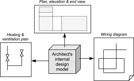
Figure 7.1: Examples of representations as realisations of viewpoints
In Figure 7.2 we identify the four main viewpoints that we will use to categorise design notations in this book. The attributes that each of these models can be described as follows.
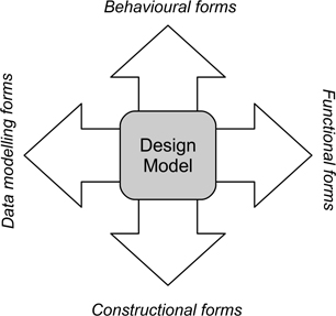
Figure 7.2: Examples of representations as realisations of viewpoints
Constructional forms are concerned with how the elements of the model are composed together to create the application, and hence model the different ways in which the elements are coupled and the resulting dependencies. This is essentially a static projection from the design model.
Behavioural forms describe the causal links that connect events (internal and external) and system responses. As a viewpoint it models the dynamic interactions arising from events that cause transitions between the different states of a system.
Functional forms describe the actions performed by a system or application. These may depend upon such aspects as information flow, or the sequencing of actions, depending upon the nature of the system and its architectural style.
Data-modelling forms are concerned with the different data elements used in the system and the relationships that occur between them.
What we need to remember is that this is a classification scheme rather than some fundamental characteristic of software. What the different viewpoints ‘capture’ is some of the different characteristics of software, and hence of our ideas about the design model itself. And since each representation used to describe a viewpoint describes a particular set of design attributes, there may be some overlap between these, as shown symbolically in Figure 7.3, providing some potential for checking consistency between viewpoints with respect to the model itself.
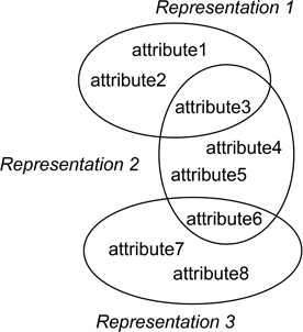
Figure 7.3: Some attributes may appear in more than one representation
What is more, these viewpoints can themselves be further classified as being ‘direct’ viewpoints, in that they are created directly by the designer(s). We can also identify viewpoints that may be described as being ‘derived’ viewpoints, created by applying some form of transformation to the design model. The most obvious such form occurs when some form of interpreter is used to ‘execute’ the design model (usually a behavioural description of the model), rather akin to the process of mental execution noted earlier and described in (Adelson & Soloway 1985).
While this scheme of classification is quite practical for our purposes, it is by no means the only way that we can classify design descriptions. A widely-cited form that is used for describing object-oriented models is Kruchten's 4+1 View that uses the labels: logical, process, development, physical + scenarios (Kruchten 1994). While less general-purpose than the scheme used here, there are some similarities, including the common recognition that some characteristics are not necessarily uniquely represented in one single viewpoint.
In the rest of this chapter we examine the characteristics of each viewpoint and identify the attributes of design elements that are modelled in these. In the chapters that follow, we will then look at some examples of how these viewpoints are modelled for some of the major architectural styles.
7.2.1The constructional viewpoint
Constructional descriptions are produced at various stages in the development of the design model. Plan-driven approaches used with call-and-return architectures will develop constructional models towards the end of the design process, whereas those used with object-oriented styles as well as more dynamic forms of development such as the Agile forms may identify the major constructional elements at relatively early stages. And the choice of architectural style at an early stage of any development process essentially constrains the choices available to the designer. (Plan-driven methods tend to be organised around a specific architectural style, so adopting a particular plan-driven design approach also determines the choice of constructional form.) Constructional information is also dependent upon the particular forms of packaging used in an architectural style (classes, sub-programs, processes etc.) and how they interact.
Figure 7.4: Construction and construction units
When thinking about how to actually construct software applications, and the way that the different elements interact, our ideas are likely to be concerned with coupling and the different forms it can take within the organisation of an application. Table 7.1 identifies some of these forms, as well as what needs to be described for each of them.
Form of Coupling |
Description |
|---|---|
Invocation |
The key attribute being modelled here is that of transfer of control, whether this be between sub-programs (call-and-return), methods, processes, objects, services or any other packaging form related to executable code. |
Uses |
This is a rather general relationship which might involve various forms of dependency: invocation, obtaining data, using data types or some combination of these. The important aspect is that this is direct usage rather than through forms such as inheritance. |
Inheritance |
Inheritance is usually associated with an object-oriented style and is concerned with reuse and adaptation of some existing attribute. |
Data Flow |
This requires that two elements (often processes) share knowledge about the form of some data exchange. |
Data Sharing |
As implied, the coupling involves knowledge of some common data forms or data itself. |
Notations used to model this viewpoint may well combine different forms of coupling (such as uses and inheritance. (These two forms can also be considered as being rather more abstract than the other three.)
More generally, this viewpoint is largely concerned with modelling static structures rather than with any form of run-time behaviour. Even when the form modelled is something like invocation, the concern here is what is being invoked, not when it is invoked. And as a result, when we look at some examples in the following chapters, we will find that these are heavily influenced by architectural style.
7.2.2The behavioural viewpoint
This viewpoint is concerned with causal relationships, connecting ‘events’ to ‘responses’ via any necessary conditions. The associated notations tend to be far more abstract than those used for construction as the events and transitions may involve operations that are spread across a number of different constructional elements.
Many behavioural notations can be considered as examples of finite-state machines, being concerned with the transitions that occur between different states of an application (such as waiting, processing, generating output etc.), and the changes in context (events) that are required to make these transitions occur. And being concerned with dynamic relationships, these forms are useful when describing the attributes of a design model that are concerned with time in any way. However, not all aspects of timing can be handled with equal ease:
aspects concerned with sequencing of events can be described fairly well;
descriptions related to fixed-interval events are also fairly tractable;
the effects of timing constraints are difficult to represent.
Behavioural descriptions do not necessarily require that the design model has been elaborated beyond being able to provide a ‘black box’ description of a system, particularly when thinking about events in the abstract. However, they can also be used for quite detailed modelling of how system elements will be affected by events, both internal and external, and as such, this class of representations is an important one.
7.2.3The functional viewpoint
One of the harder tasks for a designer is that of describing just what an application does. It is definitely more challenging than describing how it is made up of software elements (construction) or how it will behave when some event occurs. This is largely because this viewpoint is closest to the actual purpose of producing the application and hence is strongly related to the ‘problem’ it is seeking to address (booking cars, providing an auto-pilot for an aircraft, monitoring a patient's blood pressure, etc.) and so involves a strong domain element.

However, this is also something that is likely to be described quite well in the requirements specification, although again, how it can be described may be quite challenging. So functional descriptions of a design model are apt to be expressed in terms of algorithms, data manipulation, and other software-related activities.
This also highlights one of the challenges for software designers. One of the viewpoints that everyone would like to be able to model is probably the hardest one to model! So, much of this has to be captured in the other viewpoints, making use of those characteristics where relevant attributes overlap.
7.2.4The data-modelling viewpoint
While the description of data structures need not be a very significant issue when undertaking architectural design (apart from when we are developing such intrinsically data-centric applications as database management systems of course), it is often an important aspect for detailed design. Important attributes that may need to be part of the design model include type (both in compounding data types to create new ones and in such mechanisms as inheritance, used to create new classes), sequence (in terms of structures such as trees and lists), and form.
For some classes of problem, the choice of data structures is a central one and cannot be easily divorced from the functional aspects. Like construction, data-modelling is largely concerned with static relationships, and so can sometimes be modelled using similar or the same notations as those used for construction.
7.3Design notations
Having briefly discussed what we want to be able to describe about a design model, the next question is how this might be done? As noted earlier, three forms commonly used for design representations are:
text
‘box and line’ diagrams
mathematical expressions
Of course, these are not mutually exclusive, and indeed, neither of the latter forms is likely to be of much use without a supporting textual component.
7.3.1Textual description forms
Text is widely used as a means of summarising information, both when sketching and also when producing more formal descriptions. Ordered lists, tables, and highlight boxes, as used throughout this book, provide a ready means of presenting information. Two problems with using text on its own to describe aspects of a design are as follows.
Any structure that is implicit in the information can easily be obscured, unless it can be highlighted using lists, tables or boxes. Sub-headings and indentation can help to show structure, but may be less effective over long blocks of text.
Natural-language descriptions can easily be ambiguous, and structuring text so as to avoid ambiguity can lead to the use of long and complex structures.
Text is really most effective when used in small blocks and tables. We will use some examples of these in the next chapters, but it is also worth noting that the SSADM (structured systems analysis and design method) approach to plan-driven design is one that makes effective use of text through the use of standard pro-formas to record information about certain design decisions (Longworth 1992). (SSADM was developed to meet the needs of local and national government agencies. Its designers recognised that these were organisations where staff were regularly transferred between projects and departments, and hence that design rationale could easily be lost when this occurred. So in specifying its procedures they took care to include the means of recording these. We discuss SSADM further in Chapter 13.)
7.3.2Box and line description forms
We have already seen various examples of box and line forms, and there will be many more in the chapters that follow this one. As with text, diagrams do benefit from simplicity of form, and diagrams that contain a large number of symbols may be difficult to comprehend. Box and line diagrams are easily sketched on a whiteboard or on paper, but of course, because of the invisibility of software they lack any ready visual link between their form and their meaning. Curiously, despite a long history of using such forms for describing software, there would appear to be little or no research into their form and use.
Many widely used forms have a relatively small number of symbols, possibly reflecting the issues underlying the ‘magical number seven plus or minus two’ discussed in Chapter 3. More abstract notations tend to have fewer symbols too.
For most users, diagrams are probably the most effective way of providing a clear summary of ideas about the abstract concepts and relationships involved in developing a design model. However, we should remember that this is not guaranteed, and a poor diagram is no more helpful than a block of unstructured and ungrammatical text. Like text, diagrams have both a syntax (‘how we express an idea’) and a semantics (‘what it means’) and these need to be used correctly if ideas are to be conveyed to others. However, this should not be over-emphasised, especially at the sketching phase of model development. Diagrams being used to develop ideas often have very informal syntax and semantics, possibly being created as they are drawn, and these aspects only become more important when we need to record ideas for others.
Indeed, and sometimes frustratingly for a tool-creating culture such as software engineering, this does limit the usefulness of software tools that can be used to create diagrams. Because these tools often tend to enforce syntactic rules (or at least, don't necessarily permit free use of the notation), their most useful role is probably one of record-keeping rather than diagram development.
A useful property of some of the more formal diagrammatical notations is that of a hierarchical organisation, shown schematically in Figure 7.5. This occurs where one or more forms of ‘diagram element’ can themselves be described in an expanded diagram of the same form. A hierarchical organisation offers the advantage that diagrams can be ‘layered’ into levels of abstraction, avoiding large and complicated diagrams and so aiding comprehension. Again though, this is probably of limited value when sketching, and mainly useful when creating diagrams using tools.
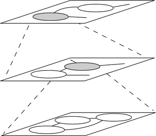
Figure 7.5: Hierarchy in diagrams
Table 7.2 summarises the details of some well-known diagrammatical notations. Most of them are ones that we will encounter in the following chapters as we look at how to model some widely-used implementation forms.
Representation |
Viewpoints |
Characteristics modelled |
Data-Flow Diagram (DFD) |
Functional |
Information flow, dependency of operations on other operations, relations with data stores. |
Entity-Relationship Diagram (ERD) |
Data modelling |
Static relationships between data entities. |
State Transition Diagram (STD) |
Behavioural |
State-machine model of an entity or system.. |
Statechart |
Behavioural |
System-wide state model, including parallelism (orthogonality), hierarchy and abstraction. |
Jackson Structure Diagram |
Functional, Behavioural, Data Modelling |
Forms of sequencing employed for operations, actions and data entities. |
Structure Chart |
Constructional |
Invocation hierarchy between subprograms. |
Class Diagram |
Constructional |
Coupling between classes and objects. |
Use Case Diagram |
Behavioural, Functional |
Interactions between an application and other ‘actors’. |
Activity Diagram |
Behavioural, Functional |
Synchronisation and coordination between the actions of an application. |
Sequence Diagram |
Behavioural |
Message-passing between elements and interaction protocols. |
7.3.3Mathematical notations
Mathematics (or at least, mathematical notation) offers scope to combine abstraction with a lack of ambiguity. Various notations for use in specifying the properties of software have been proposed (a good account of the evolution of these forms, and the claims for some of them, is provided in the review by Shapiro (1997)). These formal description techniques or FDTs have had some success, particularly where there is a need to ensure the robustness of safety-critical systems, preferably via rigorous proof mechanisms. Probably the best-known formalism is the Z specification language (Spivey 1998). There is a brief discussion of this in Chapter 18.
FDTs have particular strengths in describing system behaviour, as well as in handling some of the issues of time dependency. They can also be supported by tools that help with checking for such things as completeness. However, their use does require some training, as well as some familiarity with discrete mathematics, and so are best described in more specialist texts.
7.4Empirical knowledge related to viewpoint notations
The rather abstract nature of the material of this chapter means that there are really no directly relevant empirical studies, although there are some studies of specific notations or forms that we will cover in later chapters. However, this is a good point to mention a conceptual tool that can be useful when empirically evaluating the usefulness of notations— cognitive dimensions, sometimes also termed cognitive dimensions of notations (Green & Petre 1996, Blackwell & Green 2003). This is a set of qualitative measures that can be used to assess different aspects of what is usually termed ‘information representation’, which of course includes those forms used to provide the description of a design model, with the purpose of the dimensions being to provide a set of ‘discussion tools’ for evaluation. Here we limit our description to the original set of 14 dimensions described in (Green & Petre 1996) (the systematic review by Hadhrawi, Blackwell & Church (2017) provides a useful summary of some of the key papers describing cognitive dimensions). Table 7.3 identifies the dimensions and provides a summary of their meanings. While these are apt to be couched in terms of HCI (Human Computer Interaction), they clearly also have something useful to offer to design models in general.
Dimension |
Interpretation |
|---|---|
Abstraction |
Types and availability of abstraction mechanisms |
Hidden dependencies |
Important links between entities are not visible |
Premature commitment |
Constraints on the order of doing things |
Secondary notation |
Extra information provided via means other than formal syntax |
Viscosity |
Resistance to change |
Visibility |
Ability to view components easily |
Closeness of mapping |
Closeness of representation to domain |
Consistency |
Similar semantics are expressed in similar syntactic forms |
Diffuseness |
Verbosity of language |
Error-proneness |
Notation invites mistakes |
Hard mental operations |
High demand on cognitive resources |
Progressive evaluation |
Work-to-date can be checked at any time |
Provisionality |
Degree of commitment to actions or marks |
Role-expressiveness |
The purpose of a component is readily inferred |
Here, we briefly examine some simple examples of particular dimensions, and their application to the process of modelling.
The dimension of hidden dependencies is one that can be observed when modelling some forms of architecture, and can reflect a lack of clear encapsulation of design elements. This can be seen when we model ‘call-and-return’ structures. While our diagrams may indicate which elements are invoked by a particular element, and the details of any parameters (arguments) used to convey information between them, they may omit details of ‘global’ variables that are also used to share information, and that can affect the way that the model operates.
The wide variety of software architectural styles can make it difficult to avoid some degree of premature commitment when designing software applications. The choice of architectural style often needs to be made early in the process, and the need to work with other software applications can also influence the choice of style. This in turn can then affect the order in which we need to make further decisions.
Arguably some design notations are prone to diffuseness (we will see this in the next chapter) in the sense that the notations are overloaded with symbols or notational variations. This puts a greater cognitive demand upon the reader, who needs to remember what a diamond in the middle of a line means, or what the difference is between a continuous line and a dashed one.
This is very much an evaluation framework that can be applied (and has been) to design notations as well as to HCI design.
Key take-home points about design modelling
Modelling involves creating an abstract description that reflects the intended properties of a software application in a form that is visible, and that describes its different attributes.
Design models. Software is usually modelled by using some combination of diagrams, text and formal mathematical notations. Each of these has its particular strengths and limitations, and text in particular is often used to supplement the use of diagrams and mathematical forms.
Viewpoints. These effectively form ‘projections’ of the design model, describing specific sets of attributes, and are realised through design notations. Constructional, behavioural, functional and data-modelling viewpoints form a useful and practical set of categories for the different attributes.
Cognitive dimensions. These provide a useful set of concepts for evaluating the form of particular notations, and their limitations.