Chapter 13
Plan-Driven Software Design
Plan-driven strategies were one of the earliest mechanisms devised for transferring knowledge about software design. Essentially, the relevant knowledge schema are organised in the form of a structured sequence of well-defined activities, with the activities themselves being performed in a form appropriate to the needs of a particular application.
In this chapter we examine the nature of plan-driven design strategies, and look at some examples of the practices that they employ. As we will see, a significant limitation is that this form of strategy is less readily suited to being used with design solutions that are based upon more complex architectural styles. However, this does not make plan-driven strategies irrelevant. In particular, one of their strengths lies in the way that they ‘systematise’ the design process. This means that ensuring the integrity of the overall design model during later evolution of an application can be aided by a knowledge of the original method followed. Hence an understanding of their workings can be useful, both as a source of design ideas, and also when seeking to understand and modify legacy systems and applications.
13.1What does plan-driven mean?
A simple, but often useful, way of transferring knowledge about how to perform a task is to write down a set of general rules that describe a sequence of actions that should be followed. This approach can be particularly effective with non-creative tasks such as assembling an item of flat-pack furniture, but it can also be used to provide guidance for more creative activities.
As a very simple example, the (traditional) way that we make a pot of tea could be performed by following the plan specified below:
Such a ‘method’ puts a strong emphasis on the ordering of actions. (If you don't think so, try changing around any of the elements of the above example and see what results!) However, it provides little or no guidance about those quality-related issues that are more a matter of taste, such as:
how much tea to add
how long to wait for the tea to brew
since these are decisions based upon the personal preferences of the person making (or consuming) the tea as well as being dependent upon the type of tea.
Because they can be considered as being equally essential to the success of the tea-making process, we can reasonably assume that ‘sequence’ knowledge’ alone is insufficient for even such a relatively simple task, and that some form of ‘domain knowledge’ is also required.

Making tea
Cookery books provide a particularly good illustration of this. A recipe may provide details of certain tasks that should be done, together with a schedule (or ordering) for doing them. When followed by a novice it can be hoped that this will result in some degree of success, while the more accomplished and creative reader can interpret and adjust it to create more impressive effects. (Well, that's the basic thinking anyway.)
We can find many other examples in everyday life—the instructions followed by a hobbyist to create a model steam engine; dress-making patterns, a guide to planning a walk in the mountains etc. Taken together, these suggest that procedural guidance can also be an effective way of guiding others to perform creative tasks. However, in the first two examples the scope of the creative element is constrained—the recipe describes one particular dish, the dress-making pattern produces a particular garment. In contrast though, procedural guidance used to advise about planning a walk in the mountains will necessarily be less prescriptive, since it needs to be adapted for routes of different lengths and difficulty, as well as factors such as those arising from the size of a group etc. Hence the knowledge schema provided by such a form will require the user to employ additional expertise and complementary forms of knowledge when doing the planning (which as we observed earlier, is a form of design activity).
Plan-driven software design strategies have essentially adopted this model in order to provide guidance on designing software applications. The resulting design strategies have often been described as ‘methods’, implying a structured and procedural way of doing things.
However, we do need to appreciate that when a plan-driven approach is adopted for use with more creative tasks, such as planning walks or designing software, it is effectively operating at a higher level of abstraction than when used for describing how flat-packed furniture should be assembled. It is rather like employing a meta-recipe approach to provide guidance on how to produce a wide range of recipes, which requires much more creative input in order to adapt it to different dishes. Hence, while a plan-driven approach can provide good guidance for a task that involves a highly constrained degree of creativity, such as making tea (or coffee), it will necessarily be much less prescriptive when individual design decisions need to be driven by the needs of the problem.
Understandably perhaps, plan-driven software development is now often viewed as being mainly of historical interest. On the debit side, it does have two significant limitations: one is that it is implicitly tied to an overall ‘waterfall development’ context; the other is that it is more likely to be effective with less complex software architectures. On the positive side, many applications have been successfully developed using a plan-driven strategy; and some important concepts (such as coupling) have emerged from its use. And of course, as mentioned earlier, an understanding of how such strategies are organised can help with preserving the integrity of the resulting design during maintenance.
13.2Decompositional and compositional strategies
While an opportunistic strategy may commonly be used by experienced software designers (Visser & Hoc 1990), such an approach cannot readily be incorporated into a plan-driven structure. Plan-driven methods therefore organise their guidance around one of two major problem-solving strategies.
13.2.1Top-down decomposition

Decomposition
When early software applications were being developed, a common choice of architectural style was one of call-and-return, since most implementation languages had features that mapped closely to the structure of the underlying machine, aiding generation of efficient code. Applications therefore employed some form of ‘main’ program unit (often incorporating any permanent and global variables) and a set of sub-programs, with these performing their tasks using local variables that were only in scope while the sub-program was executing. So early thinking about design was focused upon how to map application functionality on to such a structure.
In a pioneering paper, Niklaus Wirth (1971) proposed the use of a process in which the task to be performed by the overall problem was gradually decomposed into a set of smaller ones (termed stepwise refinement). As envisaged by Wirth, both functionality and also data were to be refined in this way, and duly mapped on to the main program and sub-programs. Among the lessons that he derived from this model were two that we might usefully note here.
The modular structure resulting from this process determines the ease with which a program can later be adapted to meet changes in the requirements or its context. Although this idea is demonstrated in his paper, the changes illustrated in his example were ones that largely extended the functionality involved in the original problem posed, and we should note that the ideas about information hiding later expounded in Parnas (1972) provide a much more coherent strategy for determining the choice of modular structure.
Each refinement in the process of decomposition embodies a set of design decisions that are based upon specific criteria. This reflects the recognition that, as we have already observed many times in this book, designing software is not an analytical process, with a need to assess (and re-assess) the influences of a range of factors at each design step.
Wirth's paper was undoubtedly a seminal one, but although his ideas were centred upon the concept of modularity, his paper provided no criteria that a designer could employ to compare between possible choices of module structure (Shapiro 1997). However, the concept of module coupling introduced in (Myers 1973), that later formed one of the underpinnings of the ‘structured design’ school of thinking (Stevens et al. 1974) that are examined later in this chapter, did provide criteria that could be used to assist the process of stepwise refinement, and so coupling became an underpinning concept used as part of this approach.
Myers argued that the “primary goal in designing a modular program should be to decompose the program in such a way that the modules are highly independent from one another”. He advocated the use of ‘strong modules’, which performed a single, well-defined function and he identified some of the ways in which coupling between modules could arise.
13.2.2Compositional design strategies
A rather different, and often more challenging, way of creating a design is to use a compositional strategy. Whereas the decompositional approach tends to focus upon creating the structure of the resulting application around consideration of its function, usually realised through by the operations that an application needs to perform, a compositional approach seeks to create a design model that is formed from the descriptions of a set of distinctive entities or components that can be recognised in the problem, together with descriptions of the relationships that link these entities. The nature of the entities and the relationships will vary with the method and the architectural style that is adopted. Indeed, whereas decompositional forms are effectively constrained to producing design models using an architectural style such as call-and-return, compositional strategies can be used to create design models for a variety of architectural styles, including those using processes and objects.
Employing a compositional approach is usually considered as being less intuitive than the use of top-down decomposition (Vessey & Conger 1994). In part this may be because of its greater complexity, requiring a more mixed set of viewpoints for creating the design model, and also because it provides more scope for opportunistic decision making. However, it can be argued that the use of this strategy is likely to lead to more consistent design solutions, regardless of who is doing the design, since the design strategy aims to relate the structure of the ‘solution’ (design model) to that of the ‘problem’ rather than the structure of the underlying machine (Détienne 2002). The process of compositional design also places an emphasis upon ‘grouping’ elements when elaborating the design model, where groupings can be based on criteria such as the different forms of coupling, which again may be related closely to both the problem as specified in the requirements and the chosen architectural style.
Composition
13.3What do plan-driven methods provide?
One question we should ask at this point is why should anyone want to use a plan-driven method? Probably far more software has been developed without using anything in the nature of a ‘method’ than through the use of such methods, so what benefits does their use confer? To answer this, we first need to look at the mechanisms they employ in a little more detail.
Vessey & Conger (1994) suggested that the knowledge involved in following a plan-driven strategy can be categorised into two forms:
declarative knowledge, which describes the tasks that should be performed at each step in the process; and
procedural knowledge, consisting of knowledge about how to employ a given ‘method’ in a particular situation.
In terms of our example of making tea, the declarative knowledge involved would consist of an understanding of the tasks to be performed and of the order in which they should be performed, while procedural knowledge would address such issues as how much tea to put in the pot and how much water to add in order to make tea for four people.
Declarative knowledge schemas can be codified by providing a ‘do this, then do that, then follow this by doing…’ form of description, whereas procedural knowledge schemas are more likely to be acquired from experience and best codified in the form of advice. Since we often express the declarative knowledge in what we might term a procedural form, by specifying the sequence of actions that should be performed, this terminology can also be a little confusing. (And it is worth noting that in (Détienne 2002) the terms declarative and procedural are used in yet another, slightly different, way.)
As used for software design, plan-driven methods generally embody the relevant design knowledge through the use of three main elements.
The representation part consists of a set of notations that can be used to describe (or model) both the characteristics of the original problem and also that of the intended ‘solution’ (the design model), using one or more viewpoints and different levels of abstraction.
The process part provides the declarative knowledge by describing the procedures to be followed in developing the design model, and suggesting strategies that can be used and adopted when making any design choices involved. Following this usually involves the designer in making one or more transformations between the different notations that comprise the representation part.
A set of heuristics or clichés provides guidelines on the ways in which the activities defined in the process part can be organised or adapted for particular classes of problem. These may well be based upon experience of past use.
In terms of the classification employed by Vessey & Conger (1994), the process part can be considered as embodying declarative knowledge, while heuristics provide a means of supplying procedural knowledge. (The representation part is a vehicle for capturing knowledge about the design model rather than a mechanism for creating it.) We will use these three elements as a framework for discussing how the examples of plan-driven forms discussed in the rest of this chapter are structured.
However, to return to the question posed at the start of this section, namely what benefits do users hope to obtain from using a ‘systematic design method’, it can be argued that some of the benefits are as follows.
The representation part of a design method provides an artificial framework to help with thinking about an invisible set of elements. Portraying ideas about something that is invisible is inevitably a challenging issue when designing software, and the representation part of a method does provide a syntax and semantics to aid this through the notations adopted.
Design methods can assist with managing some of the effects of scale and of the cognitive load this imposes, particularly where teams are involved. They do so by ensuring that consistent forms of description are used for sharing knowledge among a team. Recording design plans in a consistent manner may well be important for future evolution (and while they may not necessarily reduce the technical debt involved, they can at least help with making it explicit). However, while design records may help a maintenance team to understand the intentions of the original developers (Littman et al. 1987), as Parnas & Clements (1986) have observed, such documentation may well be more helpful if it describes an ‘idealised’ process rather than the more opportunistic strategy that may well have actually been followed, even for a plan-driven method.
As already noted, plan-driven methods act as a knowledge transfer mechanism. Observational studies suggest that although experienced designers may often work in an opportunistic manner, this practice may be less well-formed and reliable when the designer is less familiar with a problem or its domain (Adelson & Soloway 1985, Guindon & Curtis 1988, Visser & Hoc 1990). So for the inexperienced designer, or the designer who is working in an unfamiliar domain, the use of a systematic design method may help with formulating and exploring a design model. Hence to some extent at least, method knowledge may provide a substitute for domain knowledge, where the latter is inadequate or lacking.
Figure 13.1 is a revised form of the ‘problem-solving’ model that we originally saw in Figure 1.1. Part (b) has been revised to show how a plan-based design strategy addresses the problem of ‘solving’ an ISP (and is much simpler than the form described in Figure 1.1). We can also see that in some ways, the problem-solving process in Figure 13.1(b) is much closer to the form in Figure 13.1(a), which describes how we solve WSPs. Of course, this is rather idealised, since iteration may well occur between the steps of a method, but nonetheless, the design process involved is a much more constrained one.

Figure 13.1: Addressing an ISP using a plan-driven form
However, while a systematic design method may help to structure the strategy used to address an ISP, it cannot magically turn it into a WSP, and in particular, the designer's choices and decision-making will still need to be made on the basis of the problem being addressed. What a design method assists with, is guiding the designer about determining when it might be appropriate to make those decisions.
It may be helpful here to return briefly to the analogy of the recipe for cooking. A recipe describes the process that should be followed in order to create a particular dish, in much the same way as a software application may embody the algorithm needed to rank the positions of the nearest cars for the CCC. Designing software applications is therefore rather like designing recipes, it requires the designer to possess insight into the problem domain; to be aware of the potential that is present in the various available materials; and to appreciate the bounds upon the software application (or cook) that will perform the task. So plan-driven (and other) design methods are essentially strategic in their scope rather than prescriptive.
The rest of this chapter looks at some examples of plan-driven forms. Of necessity the descriptions have to be brief (a full description for any of them merits a book in itself). However, they should be sufficient to show how plan-driven strategies have evolved and something of the way that they can help with addressing the problem of designing software.
13.4SSA/SD: example of an early plan-driven form
The structured systems analysis/structured design (SSA/SD) method in its various flavours provides a good example of an early plan-driven approach to design. It is one that evolved over a period when software applications were getting larger and ideas about how to design software were in a rapid state of evolution. SSA/SD was by no means the only approach to software design being explored and documented in this period, but became quite a widely-used form, perhaps because it stemmed largely from work performed by IBM, which was then a leading organisation involved both in developing software and also researching into the associated issues. Various authors published books describing forms of SSA/SD (Gane & Sarsen 1979, Page-Jones 1988, Connor 1985), as well as variants such as real-time applications, covered in the books by Hatley & Pirbhai (1988) and Ward & Mellor (1985). For this section we will largely follow the form described by Page-Jones (1988).
As a design method, this one is really a composite of two separate but related techniques. Structured systems analysis is concerned with modelling the problem-related characteristics of the application, making use of a set of representation forms that can also be used for architectural design. Structured design is then concerned with the ‘solution’-related aspects involved in producing a design model.
In its early forms, the basic design strategy was a refinement of top-down design, with the choices involved in the functional decomposition process being moderated and constrained by considerations of information flow, and to a lesser degree, of data structure. Subsequent variants adopted a more compositional approach for the analysis stages, based upon such techniques as event partitioning (Avison & Fitzgerald 1995). There were some later developments that tried to adapt the approach to an object-oriented style, but these do not seem to have been adopted very widely, and apart from these, the evolution of SSA/SD forms effectively appears to have come to an end in the later 1980s at a time when ideas about software architecture were evolving rapidly.
In the rest of this section we briefly examine the representation part, process part and some of the heuristics used in this method.
13.4.1SSA/SD representation part
The two techniques make use of quite different notations. The structured systems analysis element primarily builds a problem model using data-flow diagrams or DFDs (see Section 9.2), while the structured design component creates a design model around the use of structure charts (see Section 9.5).
The functional model created by using the DFDs can be augmented through the use of more detailed descriptions of the bubbles in the form of ‘process specifications’ or P-Specs, where these can be regarded as providing a subsidiary functional viewpoint. A P-Spec is a textual description of the primitive process represented by a bubble, summarising the process in terms of its title, input/output data flows and the procedural tasks that it performs.
An additional element of the ‘problem model’ is a Data Dictionary. This can be used to record the information content of data flows, drawing together descriptions of all of the data forms that are included in the DFDs, P-Specs and any other elements that might be used. In its initial form this should be highly abstract and avoid focusing upon physical format (Page-Jones 1988).
Whereas problem modelling can use a variety of supplementary forms (such as ERDs and state transition diagrams), the solution modelling part is confined to using structure charts. As observed earlier, the structure chart is a program-oriented form of description that maps on to the call-and-return style.
13.4.2SSA/SD process part
The process embodied in this method can be regarded as an elaboration of the basic top-down approach based on functional decomposition, being extended by adding such elements as consideration of information flow. A simple description of the process is as follows.
Construct an initial DFD (the context diagram) that provides a top-level description of the application in terms of a single bubble together with a set of inputs and outputs.
Elaborate the context diagram into a hierarchy of DFDs, and while doing this, develop the accompanying data dictionary.
Use transaction analysis to partition the DFD into tractable units that each describes a specific ‘transaction’.
Perform a transform analysis upon each of the DFDs resulting from Step 3, in order to produce a structure chart for the corresponding transaction.
Merge the resulting structure charts to create the basic design model, refining them as necessary to address issues such as initialisation, error-handling and other exceptions that are not part of the main operational activities.
Figure 13.2 provides a schematic model of this process. In part a), we see the complete system DFD produced from steps 1 and 2. Part b) shows the process of transaction analysis, with the DFD being partitioned into three smaller DFDs that address specific tasks (the dashed lines show the divisions). In part c), transform analysis has been used to create structure charts for the three transactions, and then finally in part d), these have been combined to create the complete design model for the application program. (This is very idealised, and we have assumed here that the functionality in each bubble can be readily mapped on to a single sub-program.)
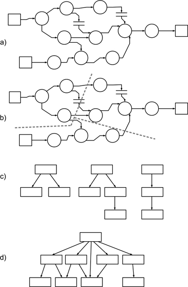
Figure 13.2: A schematic model of the SSA/SD process
Each of these steps involves what we might consider to be design activities (use of the term ‘analysis’ in this method can be a bit misleading). Steps 2-4 form the core of the method, and as we might expect, while there is guidance available about how to perform these tasks, actually mapping them on to a real problem is a task ‘left for the reader’. Transform analysis in particular is where the design model becomes modified, and while the emphasis upon data and function is retained, the logical model embodied in the DFDs is changed into a ‘physical’ model that maps on to sub-programs.
13.4.3SSA/SD heuristics
Heuristics are often created when a particular design method is used on a set of broadly similar problems. This does not seem to have been the case with SSA/SD although a number of heuristics have become established to provide guidance on such tasks as creating a DFD, or performing a transform analysis.
A technique that we should mention here is that of factoring, used to separate out the functions of a module, where the operations of one module are contained within the structure of another. Factoring can be considered as a reflective activity aimed at reducing the size of modules, clarifying their features, avoiding duplication of operations and helping with reuse of design elements. Some of the tasks of Step 5 above are related to factoring and together they highlight the way that the use of such design methods may still depend upon an additional design element in order to produce ‘efficient’ design models.
13.5SSADM: a designed design method
Our second example is a plan-driven design method that has rather different origins, and hence provides some interesting features. SSADM (structured systems analysis and design method) was developed by Learmonth & Burchett Management Systems on behalf of the UK government. It was intended to support the development and long-term maintenance of data-intensive systems since the use of these, and hence their systematic production, was seen as playing an important role for both central and local government agencies.
Part of the rationale for commissioning such a development was the way that public bodies in the UK are traditionally organised. In particular, central and local government agencies often move staff to new posts on a regular basis (the UK civil service has tended to favour the idea of the ‘generalist’ over the ‘specialist’, and hence staff development tends to require the gaining of wide experience). Where such roles involved the responsibility for software development, it was considered that regular change of staff could (and did) lead to discontinuity in the way that the software applications were developed, and hence that using a mandated approach for their development would help overcome this.
SSADM Version 3 was the first stable version of the method, and was supported by a small number of textbooks. This evolved into Version 4 in the early 1990s, at which point the method was considered to be ‘mature’, and which appears to have marked the end of development for both SSADM and for the textbooks supporting it (Longworth 1992, Weaver, Lambrou & Walkley 2002). This period also coincided with the growing uptake of object-oriented platforms, which would have been likely to compete as an alternative strategy for use in government projects.
13.5.1SSADM representation part
The forms adopted for SSADM largely reused established ideas and notations, albeit with some (sometimes rather confusing) renaming and relabelling. SSADM analysis and modelling practices address the following main viewpoints.
Data relationships. These are modelled using the fairly conventional entity-relationship diagram, relabelled as a logical data structure (LDS), with the modelling process being termed ‘logical data modelling’, or LDM.
Data flow. This is modelled using a form of DFD, which is either developed by transformation of an existing application or through decomposition. However, these are more solution-oriented than the ‘bubble’ forms used by De Marco and others for analysis.
Function and behaviour. Modelling of these viewpoints uses entity-life-history (ELH) diagrams that have the same form and syntax as a Jackson structure diagram (Jackson 1975).
Figures 13.3 to 13.5 provide examples of each of these forms. Within the Jackson structure diagram notation, a ‘plain’ box signifies a single action within a left-to-right sequence, a box with a star in a corner indicates iteration of the action (including the possibility of no action), and boxes with circles indicate selection between optional choices. For the latter, an unlabelled box indicates that one option might be ‘do nothing’. At any level of expansion of a branch of the model, only one form (sequence, iteration, selection) can be used—they cannot be mixed.
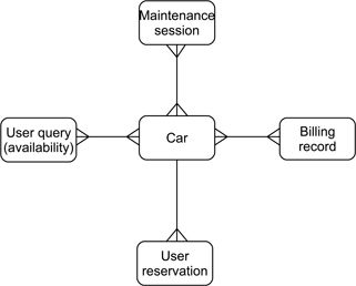
Figure 13.3: Example of an LDS

Figure 13.4: Example of a DFD using SSADM notation
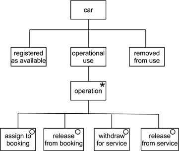
Figure 13.5: Example of an entity-life-history diagram
13.5.2SSADM process part
Declarative knowledge is embedded into SSADM through a strongly hierarchical process, with three top level phases. The first (a feasibility study) is optional, and the other two phases each consist of three stages. The stages are further sub-divided into steps which in turn each encompass a set of one or more tasks. Figure 13.6 uses the Jackson structure diagram format to describe the top levels of the process part.
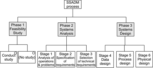
Figure 13.6: The SSADM process part
SSADM practice is very much focused upon the idea of producing a logical design for an application, and this is only mapped on to a physical design in the final stage. So, in principle at least, there is no strong coupling to a particular architectural style. SSADM is also a very bureaucratic method, as might be expected from its origins and purpose. Figure 13.7 provides an example of Step 320 (the first digit indicates which phase of the method this concerns). Note in particular that there is also a strong emphasis upon documentation, which again has an important role in this method. However, when we examine empirical knowledge about plan-driven forms in Section 13.7 we will see that the procedures of SSADM can be, and have been, used in part without necessarily employing the complete method.
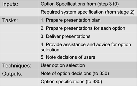
Figure 13.7: Step 320: user selects from technical options
13.5.3SSADM heuristics
SSADM can be regarded as using rather formalised heuristics in a number of the steps, referring to these as techniques. There are 13 of these, and their main role is to provide procedural knowledge that can be used to help develop the diagrams, with SSADM placing heavy emphasis on the use of matrices for this purpose. A matrix in this context is a grid or table that helps with identifying links between elements, rather as the state transition table described in Section 9.3 can be used to develop state transition diagrams.
However, these could also be regarded as providing declarative knowledge as well as procedural knowledge, although it can be argued that their use augments the SSADM process rather than forming a part of it. Figure 13.8 shows an entity-life-history matrix (ELH matrix) that can be used to help produce the ELH diagram shown in Figure 13.5.

Figure 13.8: Example ELH matrix
13.6Plan-driven design for object-oriented models
Early thinking about how to design object-oriented systems not unnaturally sought to use experience from the approaches used to design applications that used call-and-return and other forms of software architecture. Since plan-driven forms were then the main established vehicle for knowledge transfer, it was not surprising that design ‘methodologists’ sought to extend the use of what was generally considered a generally effective approach. Indeed, many ‘first-generation’ OO design methods made varying degrees of use of existing ideas and notations.
However, while in principle, plan-driven approaches are a viable means of providing knowledge transfer about OO design, the greater complexity of the OO model, when compared to architectural styles such as call-and-return, has tended to result in a correspondingly greater complexity of structure for associated plan-driven approaches.
This section examines two OO plan-driven methods (Fusion and the Unified Process). Both represent attempts to create a second-generation plan-driven method by merging ideas from first-generation OO methods that were seen as effective. In many ways, the UP can also be considered as the point at which the use of a plan-driven form both achieved maximum complexity, and also started to morph into more agile forms.
13.6.1The Fusion method
As indicated above, Fusion can be viewed as being a ‘second-generation’ OO method. Indeed the methodologists at the Hewlett-Packard Laboratories in Bristol UK who developed Fusion described their goal as being to “integrate the best aspects of several methods” (Coleman, Arnold, Bodoff, Dollin, Gilchrist, Hayes & Jeremes 1994). Among the problems intrinsic to an object-oriented approach that they identified as drivers for their work, the method developers included the following.
Difficulty with finding the objects. They observed that “finding the right objects and classes in an object-oriented system is not easy”.
Function-oriented methods being inappropriate. Their observation here was that for OO applications, the traditional methods of analysis and design (that is, those based on data-flow and function) “no longer work”. Implicitly, the use of these was seen as a weakness of many first-generation approaches. In particular, they noted that “functional decompositions clash with the object structure of the implementation”.
While Fusion seems to have had some early success in terms of its adoption, it never seemed to acquire a solid base of users. The text by Coleman et al. (1994) remains the only readily available description of the methods, and seems to be mainly cited when authors are discussing OO methods. Wieringa (1998) did note that there had been some subsequent development of the method, but that these were not readily accessible, and so the description provided here is that described in the 1994 version. Since the more distinctive element of Fusion lies in the process part, we describe this first (there are no evident heuristics).
The Fusion process
Reflecting the need for more complex processes to address the more complex architectural style created by the use of objects, the Fusion process has no fewer than eight distinct steps. Four of these are classified as analysis (black box modelling) while the other four are white box design steps. Continuity through the overall process is provided through the use of a data dictionary, which is intended to act as “a central repository of definitions of terms and concepts”. Arguably, this is the one element that is most evidently (and sensibly) carried over from earlier structured design practices. The eight steps are shown in Figure 13.9, and can then be summarised as follows.
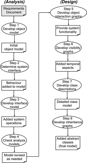
Figure 13.9: The Fusion design process
Develop the object model. While the task of this step is identified as identifying a set of candidate classes, relationships and attributes, the method does not specify how this should be done. The outcomes are a set of entries in the data dictionary, plus a set of diagrams making up an initial object model for the system as a whole, together with its environment. Advice on conducting this step includes using brainstorming and noun-verb analysis1.
In addition to identifying candidate classes, relationships and attributes, this process should also identify any invariants and record their details in the data dictionary. For our purposes an invariant is some form of constraint upon the overall state of the system.
Determine the system interface. The model from step 1 is essentially a static one, and this step extends it to describe the dynamic behaviour of the system as a whole. In doing so, it also clarifies the system bounds by determining what is, and what is not, included in the system itself.
The core concept here is that of the event, with the designer being encouraged to think of how the system is to respond to external events as well as to consider what events will be generated in response to these. The approach suggested is to consider a set of scenarios of use, modelled as timeline diagrams (essentially message sequence diagrams, as described in Section 10.6), extending the data dictionary to include these scenarios.
Development of the interface model. The first element of this involves creating a set of use cases that generalise the scenarios from the previous step (termed life-cycle expressions). These are then used as the basis for the ‘operational model’ that defines the semantics (meaning) for each system operation, expressed in terms of informal pre-condition and post-condition specifications. Overall, this provides a functional description of the system.
Check the analysis models. This step is intended to ensure completeness and consistency in the (still black-box) model, rather than extending it in any way. Completeness is largely a matter of cross-referencing with the requirements specification (a limitation of plan-driven models is that they implicitly require a requirements specification as their starting point). Consistency is concerned with ensuring that the different viewpoint models from the previous steps (which we can categorise as being constructional, behavioural and functional) as well as the invariants represent the same overall design model. This can be partly achieved by using scenarios to trace event paths through objects.
Develop object interaction graphs. The first step categorised as being ‘design’ is used to describe the designer's intentions about how the objects will interact at run-time to provide the required functionality. This involves creating an object interaction graph for each system operation, and in doing so, making decisions about message passing between objects and any resulting state changes.
One of the elements also clarified in this step is the point at which objects should be created from the classes. (Although the descriptions tend to be couched in terms of objects, since these are the executable elements of the eventual system model, the model itself is really described in terms of classes—while recognising that many classes will only lead to the creation of a single object.)
A question here is whether the set of objects used in this step is essentially that created in Step 1? The answer to this is ‘yes’, as the objects involved are defined as design objects that are derived from the analysis objects. So these are still relatively high-level elements that may later need to be expanded or refined.
Each object interaction graph has a single controller object which has a message entering from outside of the particular set of objects involved in the operation, and also one or more collaborator objects that make up the rest of the set. There are two important design decisions here: one is identifying the controller, while the second is the possible need to introduce new objects (classes) to provide the required functionality.
Develop visibility graphs. These are used to describe the other classes that a class needs to reference, as well as the forms of reference to be used, and their lifetimes (whether the knowledge should persist through the life of the system, or be more transitory).
This temporal aspect is an important (and distinctive) feature of this Fusion step. However, at this point, the influence of time is largely confined to its influence upon the constructional aspects.
Develop class descriptions. This step involves drawing together the original object model with the outcomes from the previous two steps to produce class descriptions that specify the following characteristics for each object.
The methods and their parameters (derived from the object interaction graphs and object visibility graphs).
The data attributes (from the object model and the data dictionary).
The object attributes (largely from the object visibility graph for the relevant class).
The inheritance dependencies.
There are clearly quite a lot of decisions related to different forms of uses relationships in this step, and it is really the first time that inheritance structures are significantly involved (although there is provision for identifying these when creating the original object model in Step 1).
Develop inheritance graphs. While the previous step was concerned with ideas about specialisation through inheritance derived from the original object model, this step is concerned with identifying new abstract superclasses. In particular, the designer is encouraged to look at the relationships between the classes developed in Step 7 and identify common abstractions.
While some elements of Fusion are relatively loosely structured, such as the model building in Step 1, which can be expected to be strongly problem-driven, the subsequent steps provide quite good guidance on refining this. Fusion does make good use of diagrammatical notations to develop the functional and behavioural viewpoints and also to ensure consistency between the different viewpoints.
The Fusion notations
Fusion makes quite extensive use of box-and-line notations, although with a much less complex variety of forms than is used in the UML. The syntax is also less detailed than that of the UML.
Like other OO methods and the UML, the construction viewpoint employs a class diagram (termed the object model that has strong similarities to the ERD notation described in Section 9.4. A simple example of this is shown in Figure 13.10(a).
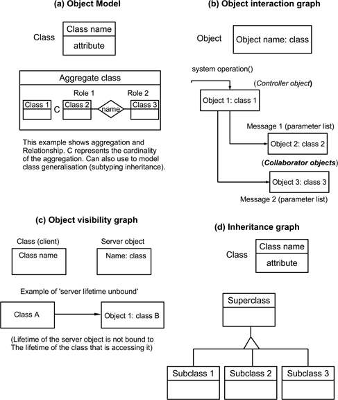
Figure 13.10: Some Fusion notation forms
Class behaviour makes use of textual descriptions. Informally, in (Coleman et al. 1994) there are examples that describe scenarios by using a form similar to the UML message sequence diagram that we described in Section 10.6.
In the later, more detailed stages of model development, functionality is described by using object interaction graphs to describe the way that objects collaborate. A graph is created for each system operation. Figure 13.10(b) shows an example of this form, which does differ rather from other notations encountered so far.
The second form of notation that can perhaps be considered as being specific to Fusion is the object visibility graph, shown in Figure 13.10(c). This is used to describe the ‘reference structure of classes in the system’, identifying the objects that class instances need to access and the forms that these references should take (including their permanency or otherwise). In effect, this notation is intended to describe encapsulation, and hence can be regarded as providing a data-modelling viewpoint.
Finally, Fusion makes use of a relatively conventional inheritance graph, which again, provides support for modelling of the constructional viewpoint. An example of this is provided in Figure 13.10(d).
Fusion—some observations
The description above, brief as it is, should be sufficient to allow us to make a number of observations about the use of plan-driven approaches to create an object-oriented model.
Fusion employs a quite complex four-viewpoint model at a relatively early stage in the design process, particularly when compared to the simpler models employed by SSA/SD in the early stages.
The process throughout is largely one of refinement and elaboration, possibly because of the more complex design model, rather than involving any element of transformation between viewpoints (a key element of SSA/SD).
The basic set of candidate objects (a major design decision) is largely determined at the very start of the process. A benefit of this is that the design options are thereby constrained from an early point, while a disadvantage is that it is then necessary to get the ‘right’ object model established very early in the process. For less experienced designers, this can be a significant challenge.
The characteristics described by the constructional viewpoint play a much more ‘up front’ role than in more traditional plan-driven approaches.
While the concept of inheritance is integrated into Fusion, it is restricted to appearing very early (seeking to recognise domain-based opportunities) or much later, looking for constructionally-based opportunities.
In terms of the characteristics of the object model, it can be argued that Fusion does provide support for all of the major ones: abstraction, modularity, encapsulation, and hierarchy. Fusion also handles the often quite difficult distinction between the class and the object quite effectively. When considering static and abstract issues, and specifying general characteristics, then the emphasis is rightly upon the class. When considering system behaviour, as well as temporal and dynamic characteristics, then the object is probably the better abstraction to employ. As a method, it does keep these distinct, and encourages the designer to use whichever is the more appropriate in the specific steps.
Fusion therefore demonstrates that the use of a fairly ‘traditional’ form of plan-driven approach appears to be feasible when designing object-oriented systems. However, key decisions about the choice of objects need to be made at a very early stage. Indeed, this need to identify key elements early is probably a disadvantage of all plan-driven approaches, regardless of the architectural style employed.
13.6.2The Unified Process (UP)
The Unified Process (UP) stems from the work of the ‘three amigos’: Grady Booch, James Rumbaugh and Ivar Jacobson. It draws strongly upon early work by Jacobson at Ericsson, and his later development of the Objectory (Object Factory) method. The UP also exists in more commercial forms, with the best known of these being the Rational Unified Process (RUP).
The authoritative text on the UP is Jacobson, Booch & Rumbaugh (1999). Two other widely-cited sources are by Kruchten (2004) and Arlow & Neustadt (2005). Perhaps because the UP is closely associated with the UML, there are also various texts on combinations with other forms, such as design patterns, described in Larman (2004).
While, like Fusion, the UP represents a merging of ideas from many sources, it differs from Fusion in two significant ways.
The sources for the UP have included some of the most popular of the available object-oriented methods and notations, as observed by Johnson & Hardgrave (1999).
The resulting process structure is much less sequential than that employed in Fusion. Its form comes much closer to RAD (Rapid Application Development) methods such as DSDM (described in Chapter 14) that represent something of an interim form between plan-driven and agile approaches.
A consequence of the first difference is that the association with the UML has meant that it uses forms that are, at least in part, more familiar to users. The consequence of the second is that it can probably be regarded as something of a ‘bridge’ between plan-driven and agile ideas. While still more structured than agile forms, it is nonetheless more iterative in terms of the processes involved than those employed by plan-driven forms. Taken together, these may at least partly explain why the UP has continued to be of interest into the 2000s, while Fusion has largely receded into the shadows. (This is not a comment or assessment about relative technical excellence, more an observation that the form of the UP has probably fitted better with the way that ideas about software development have evolved.)
The process of the UP is organised in a far less linear form than conventional plan-based methods, although of course there is an overall flow from beginning to end of the process. The main elements are as follows.
Four project-based phases of development (inception, elaboration, construction, transition) that each completes a major milestone in a project.
Each phase is organised as a set of one or more iterations or ‘mini-projects’.
Each iteration cycle involves a set of activities associated with five technically-focused workflows (requirements, analysis, design, implementation, test). The extent to which the activities concerned with each workflow are involved will be different for each phase.
Figure 13.11 is an attempt to model this fairly complex process. In particular, the workflow balance associated with each phase has been shown as a histogram (the relative heights of the bars should not be taken too literally; these are meant to be indicative). We begin with a brief look at the roles of each phase, and then discuss the activities of the workflows. Some aspects are omitted: the iterations are really a project-specific element; and we concentrate on design-related activities, which means that we say little about the implementation and testing workflows.
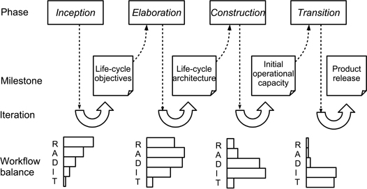
Figure 13.11: Organisation of the Unified Process
The UP phases
The phases are very project-driven and create a framework that emphasises the strong user links and iterative practices that characterise the UP (and that characterise the agile forms that we examine in the next chapter).
Inception. This phase is primarily concerned with project planning activities. However, we might note that establishing the feasibility of a project may lead to the creation of one or more exploratory prototypes. The milestone for this phase, life cycle objectives is largely concerned with the eventual deliverables for the phase (documents, models, prototypes), but does include a candidate architecture, representing the initial architectural design for the eventual application.
The milestone documents should also include:
an initial domain-based class model;
a set of domain-based use cases;
initial analysis and design models.
Although iteration is implicit, the normal expectation is that this phase should require only a single cycle. We might also note the use of use cases, a very distinctive feature of the UP and one that has been elaborated in later developments.
Elaboration. From a design perspective, this is a much more significant phase. Its purpose is to create the architectural baseline (top-level design) that will underpin further development. In doing so, there is the expectation of producing further use cases, as well as addressing questions about quality factors, including those related to performance.
The milestone for this phase, the life cycle architecture is a partial working system. The UP documentation does emphasise that this is not an exploratory prototype, although it can be argued that it is fairly close to being an evolutionary prototype. The resulting set of models will include:
static domain-based class models;
a fuller set of use cases;
analysis models (both static and dynamic);
static and dynamic architectural design models.
The emphasis upon model-building and the need to ensure consistency between them, means that some degree of iteration is likely to be needed.
Construction. Despite the name, this phase still involves some design activity. The initial operational capacity milestone corresponds to the delivery of a beta version of the application. Hence its goals include:
completion of any requirements elicitation or analysis tasks;
completion of models.
Clearly, the detailed physical design tasks form an essential element of this.
Transition. The purpose of this phase is to lead to the final milestone of product release. Hence it is unlikely to lead to any design activities unless a need for these was revealed when exercising the beta version produced in the preceding phase.
The UP workflows
A characteristic of plan-driven design methods that may by now be fairly obvious is that terms such as ‘construction’ or ‘implementation’ can mean quite different things when used by methodologists, and in particular, may involve significant design activities. For that reason we will look at all five workflows, although only with regard to the design issues that are involved in each one.
Requirements workflow. This workflow relies extensively on the use of use case modelling. Not only is the use case a rather distinctive characteristic of the UP, but a use case also has the advantage of being able to record both functional and non-functional attributes. The primary role of a use case diagram is to identify the boundaries of a use case, as shown in the example of Figure 13.12. The detailed specification of a use case is not a part of the UML model, and designers often use text-based templates, although other forms such as message sequence diagrams can also be used (Ratcliffe & Budgen 2001, Ratcliffe & Budgen 2005). Most books on the UML do discuss this issue, and there is a good introduction to use case modelling in (Arlow & Neustadt 2005).
One of the benefits of employing use cases is that they provide a good mechanism for verification of a design model against requirements. A scenario derived from a use case can provide a walk-through mechanism that directly links the two stages of development. Use cases also provide a framework for the analysis workflow.
Analysis workflow. The UP interprets ‘analysis’ in the conventional ‘black box’ sense of producing a model that describes what an application is to do, but not how it will be done. As always, the distinction between analysis and design is not completely clear-cut. The objectives of this workflow are to produce analysis classes that model elements (objects) in the problem domain and to generate use case realisations that show how the analysis classes interact in order to create the behaviour required for a given use case.
As always, identifying the analysis classes remains a challenging problem. In the case of the UP this is supported through the use cases, as each use case can be separately analysed to identify both the analysis classes and the way that they collaborate. The task of identifying the classes still remains though, and relatively long-established techniques such as noun-verb analysis and CRC brainstorming (class-responsibility-collaborator is described in (Beck & Cunningham 1989)) can be used.
The output from this workflow can be modelled by using a range of UML notational forms, including:
class diagrams to model the static properties of the relationships between objects (uses, inheritance);
collaboration diagrams and message sequence diagrams to model the dynamic aspects of the relationships between objects.
For a given use case, collaboration diagrams provide a static model of the relationships between objects—describing which elements are involved, and how—rather than the when aspects (the actual interaction) that are described in forms such as message sequence diagrams. In particular, an interaction can only occur between objects within the context of a collaboration. Collaboration diagrams can be used to model class collaborations (the descriptor form) and object collaborations (the instance form). An example of a simple use case from the CCC, described using a common tabular form, and the associated collaboration diagram is shown in Figure 13.13 (some detail has been omitted for clarity).
The UML package notation can be used to group analysis classes and use case realisations as analysis packages. Since packages can also contain other packages, the analysis model can itself be considered as being a package. A key role of this notation is to help keep track of the analysis elements, with the overall analysis architecture being defined by the high-level analysis packages.
Design workflow This forms a major element of both the elaboration and construction phases and is intended to provide the white box description of how the black box model from the analysis workflow is to be achieved.
Many of the activities are similar to those described for Fusion: identifying design objects; when to create objects from the static classes; and the persistence, or lifetime, of objects. Another consideration for this workflow is the more structural question of how to employ the inheritance mechanism. And once again, the package mechanism can be used to manage the outcomes, although the term subsystem is now used in place of package to indicate that more detail is provided.
Use cases are expected to provide a linking thread between analysis and design and may themselves need to be elaborated further.
The UP design workflow therefore addresses many detailed issues concerned with developing the design classes and their interfaces. Perhaps the main change in the modelling involved, apart from elaboration of detail, is the development of behavioural viewpoint models, largely through UML statecharts, which also helps address the issues of object creation and persistence.
As with Fusion, the white box design tasks of the UP are largely concerned with elaborating detail and ensuring consistency between the different parts of the design model. Most of the key architectural decisions have already been made as part of the analysis workflow, although obviously this can be revised by the activities of the design workflow if necessary. In that sense, like Fusion, the key structural decisions are made early in the process reflecting the more compositional approaches employed by these object-oriented methods.
Implementation workflow. This is primarily concerned with producing executable code, with the main design elements being confined to the decisions involved in translating the design model to actual implementation. Overall, this phase is not expected to form an active part of the design task.
Test workflow. As might be expected, this involves no explicit design activities beyond any required in response to the testing outputs.
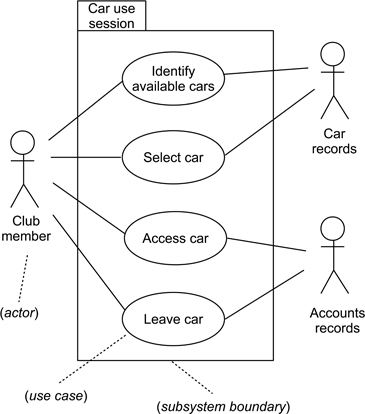
Figure 13.12: Simple example of a use case diagram
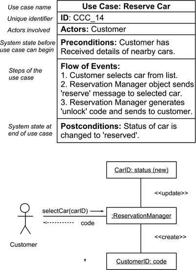
Figure 13.13: A UML use case and associated collaboration diagram
The UP—some observations
The UP design process has a much more complex structure than the other methods examined in this chapter, including Fusion. The interweaving of development phases and workflows produces a much more complex process than the more linear forms of the other design methods we have examined, and as such forms a much more challenging management task.
A key element of the UP, and one that particularly distinguishes it, is the use case. This concept provides a valuable framework that provides manageable-sized analysis tasks; a thread through requirements, analysis, and design; and a mechanism that not only partitions the tasks for these workflows, but also provides the means of being able to cross-check for consistency and correctness. In many ways the more complex UP process model would probably be impractical without the unifying theme of the use case.
13.7Empirical knowledge related to plan-driven design
The use of plan-driven design methods is perhaps more associated with the ideas of advocacy than those of rigorous empirical assessment. In the early days at least, design methodologists tended to be codifying their experiences (a quite reasonable approach to knowledge transfer in the circumstances) rather than exploring their limitations. There are a number of possible explanations for the lack of useful empirical knowledge about design methods, including the following.
By their nature, design methods both evolve and are intended to be adapted to meet different needs. This means that any attempt at evaluation of the processes involved usually lacks a widely-established and well-defined ‘baseline design method’ to study.
Software development (at least before the emergence of open source software) was largely conducted by commercial organisations—and knowledge about how it was done may well have been considered as being of too much value to allow for open publication.
As we have observed, the development of ideas about design methods rather ‘tailed off’ in the 1990s. However, this was also the period in which interest in empirical research about software engineering was beginning to become more established, and so researchers were perhaps less likely to view design methods as a topic of interest.
The most appropriate form of empirical study to use in studying plan-driven design development is probably the case study, since the subject matter needs field studies with relatively long-term data collection, and there are also likely to be many variables of interest. Unfortunately, these are challenging to perform for such a topic, and examples do appear to be lacking in the literature. Nor do there seem to be any useful observation studies.
An alternative form for collecting information about experience with design processes is the survey, and while these may collect data that can be considered as more ‘shallow’ for these purposes, a survey does offer scope to collect and aggregate user experiences. Such a survey was conducted by Edwards, Thompson & Smith (1989) to look at the use of SSADM, and other surveys have been conducted to address questions about object-oriented methods. In the rest of this section we examine their findings and observations about the use of plan-driven approaches (there were other findings, but here we concentrate on the methodological aspects).
Knowledge about SSADM. The survey by Edwards et al. was related to Version 3 of SSADM, and was conducted on an organisational basis. Requests were sent to 310 organisations in industry and in local and central government organisations, from which they obtained 117 responses, with 72 (23%) of these being usable. (Given that anything above 10% is regarded as being a good response rate for a survey, the researchers did well.) At the time when they conducted their survey, projects tended to be using programming languages such as COBOL and many were also concerned with database management systems. For the responses, team sizes involved ranged from teams with fewer than 10 up to ones with over 200 developers.
The survey revealed that SSADM was rarely used in full, with developers being selective about when to make use of it. In particular, it was noted that, while responses tended to be positive:
the techniques were generally found to be effective, but were time-consuming to employ;
the entity-life-history diagram presented most problems for developers when modelling and was the form of notation most frequently omitted;
the physical design step was the most challenging, perhaps in part because the method provided little in the way of detailed guidance about how to perform this for a particular platform.
-
Knowledge about OO design. The survey conducted by Johnson & Hardgrave (1999) used two groups of participants: experienced developers and trainees. Also, its focus was upon their attitudes and preferences with respect to object-oriented methods and tools, rather than upon the forms of the specific methods.
Separate survey forms were used for the two groups, and the sample included 102 experienced designers and 58 trainees. Since the survey was conducted on-line, there are some methodological issues regarding sampling and representativeness, as the authors do acknowledge.
The authors also observe that the degree of comparison (between methods) that could be achieved was limited. This was chiefly because “a theory explaining attitudes and behaviour toward, and use of OOAD methods does not currently exist”. Hence they argue that the survey offered an inductive approach that would “use facts to develop general conclusions” and lay some of the groundwork for the development of such a theory.
In terms of comparisons, the survey was chiefly concerned with the degree of training provided for developers, their familiarity with, and preference between, different object-oriented methods, and their attitudes towards them.
The methods covered by the survey were chiefly what we might term as ‘first generation’ design methods, although the set of methods did include Fusion as well as the three methods that were subsequently brought together in the Unified Process. Their findings included the following.
A relatively large proportion of time was spent on analysis and design of objects, relative to the time spent on coding and testing when compared with ‘normal’ expectations for software development. It was thought that this might be because creating the design for an object was more time-consuming than the equivalent task for other architectural styles.
Adopting object-oriented methods involved a steep learning curve (although the respondents did regard this overhead as useful once the knowledge had been acquired). This is consistent with an earlier study on the overheads of learning analysis and design for different forms of software architecture (Vessey & Conger 1994), which also observed that OO concepts could be challenging to use.
The limited expectations that respondents showed about code reuse. Here the authors observed that “one of the most advertised benefits of OO is reuse, yet developers rated this lower than trainees”. Their conclusion was that “this is perhaps a case of trainees believing the hype about reuse and developers actually realising the difficulty in creating reusable code”.
Overall, the survey did find high levels of satisfaction with object-oriented methods, both for analysis and design. However, as the authors did caution, this might have partly been an artifact caused by the self-selection of participants, since those with a positive view of OO might be more likely to have responded to the invitation to participate.
Unfortunately, there are no later surveys that can be readily identified in the literature, probably because the use of plan-driven methods with OO effectively ‘ran out of steam’ with the development of the Unified Process. The systematic mapping study described in Bailey et al. (2007) found relatively limited empirical research into the object paradigm as a whole, with most emphasis being upon studies involving metrics,
Key take-home points about plan-driven design practices
Knowledge transfer. Plan-driven design practices provide method knowledge as the means of organising the design process, with this acting as a substitute for domain knowledge where appropriate. The process itself is usually organised as a sequence of ‘analysis and design’ steps that provide a solution modelling process for an ISP that is more akin to that for a WSP.
Design input. Although plan-driven forms provide a structure that can help organise the design process, it is important to appreciate that the design decisions made within this are still ones that are based upon the needs of the application. Using a plan-driven approach requires that the designer possesses method knowledge, an understanding of the problem, and an appreciation of relevant design criteria.
Plan-driven design strategies. These usually consist of a mix of a representation part; a process part; and a set of heuristics used to help adapt a strategy or method to a particular type of problem. The process part incorporates declarative knowledge about how the design task should be organised as a set of steps. The heuristics provide procedural knowledge about how to employ the method for a particular type of problem.
Context. Plan-driven methods implicitly assume a ‘waterfall-like’ development context. This is chiefly because they build their initial analysis models around the elements of the requirements specification. While this doesn't preclude making later changes to the model, the assumption is that the requirements specification is a comprehensive description of the design goals.
Architectural form. Earlier plan-driven methods were concerned with relatively simple architectural styles such as call-and-return, where the dependencies (coupling) between design elements used only a limited set of forms. Use of plan-driven approaches has proved more challenging with such styles as the object-oriented model, where there are many forms of interaction that can occur between the elements of a design.
Effectiveness. There are few empirical studies available to provide any insight into this. One benefit of using a systematic plan-driven approach is that it helps constrain the structure of the resulting design model, which in turn may assist with later evolution of the model. Perhaps one of the main disadvantages of the plan-driven approach is that it can be bureaucratic, with a significant overhead of documentation—although as in the case of SSADM, that may be considered as a benefit.