Chapter 10
Modelling Objects and Classes
The object paradigm is well-established as a major architectural form and it is one that is widely employed for developing software applications across a wide range of domains and that is supported by many programming languages. While undoubtedly a very versatile form for constructing software applications, objects (and the associated classes) are quite complex structures, and much more complex than the single-threaded processes that were the topic for the previous chapter. And not only are they more complex in their structure, there are also many different forms of relationship (coupling) that can occur between objects, adding to the challenges that they present for modelling.
As a further factor that may need to be considered when modelling object-oriented structures, objects can also be realised in different ways, and this occurs with programming languages as well as run-time systems. For example, Java uses a different object model to that used by C++. In particular, Java only allows the use of single inheritance (inheriting from only one class), whereas C++ permits an object to inherit from more than one class. In this chapter we take a fairly generic approach to modelling objects, but in practice this may be constrained when it is necessary to map the design model on to a particular form of implementation.
The chapter therefore begins by examining the general characteristics of objects and classes (and the distinctions between them), in order to provide a basis for the sections that follow. An awareness of these characteristics, and how they can be employed, provides an important foundation for considering how they can be modelled. Following that, we examine the different relationships that are encompassed by the concept of coupling between objects, and then go on to look at some of the ways that we can describe and model these relationships between objects and classes.
10.1Characteristics of objects and classes
In order to model software objects we need to have a set of clear ideas about what makes up the object paradigm. Unfortunately, clarity has not always been a quality associated with the object-oriented paradigm. Indeed, the words of Tim Rentsch (1982) could be viewed as having been quite prophetic:
(Of course, this extended well beyond the 1980s, and we could substitute a whole list of terms or phrases in place of ‘object-orientated’, including agile development, software design patterns, global software development, model driven development, cloud etc. What Rentsch was really observing was the way that different forms of software development practice have in turn been seen as ‘silver bullets’ (Brooks 1987).) Unfortunately, silver bullets don't magically turn ISPs into WSPs, although it can be argued that while objects are unquestionably complex things, they do provide the means to model the complexity inherent in software-based ISPs.
A good overview of the concept of an object was provided in Booch (1994), which includes a survey of historical issues associated with objects. The analysis by Taivalsaari (1993) used a rather different framework and examined the notion of an ‘object’ from five different ‘viewpoints’: conceptual modelling; philosophical; software engineering or data abstraction; implementation; and formal. For the purposes of this chapter however, a rather shorter description of the characteristics of objects (and classes) will be sufficient.
10.1.1The notion of an object
When seeking to pin down the notion of what distinguishes an object, a useful starting point may be to contrast the idea of an object with that of the process that was the topic for the previous chapter. Processes are usually single-threaded, especially when implemented in a call-and-return style. While they may exhibit state, this is rarely readily accessible outside of the process, and, for sub-programs any variables may be transient and only exist when the sub-program is executing. There are variations on all of these of course (that's why we have so many programming languages and platforms), but from a modelling aspect, the process is a relatively simple element, and one that is essentially ‘action-oriented’, with structures that place relatively little emphasis upon data or information.
Figure 10.1 provides a simple illustration of the distinction between the way a process is organised and the way that an object is organised. On the left of the figure, we have a process consisting of sub-programs that make use of other sub-programs through invocation, and that can access global data structures that are held in the main body of the program. On the right of the figure, we have an object that provides multiple entry points to the resources it provides through different external methods, that contains permanent encapsulated data structures, employs both external and internal methods, and that can make use of other objects in a number of different ways.

Figure 10.1: Processes versus objects
As we noted in the last chapter, the emphasis placed upon ‘action’ in processes was challenged by David Parnas (1972) with his ideas about information hiding. Objects incorporate this concept via an encapsulation mechanism that makes it possible to create applications in which the detailed forms used to store and organise data elements are only known to a few key parts of a system.
As various ideas began to merge around the concept of objects in the 1980s, various efforts were made to maintain consistency of concepts and terminology. A useful contribution to this was made by a working group at Hewlett-Packard, for which the findings (in the form of a discussion of exactly what objects are) were reported in (Snyder 1993). A little later, the emergence of the Unified Modeling Language (UML) provided a set of ideas about the nature of objects that were influenced by abstract modelling. Although originally the work of the ‘three amigos’ (Grady Booch, Ivar Jacobson and James Rumbaugh), the UML and its evolution subsequently came under the umbrella of the Object Management Group1 (OMG), and at time of writing the latest specification of the UML is that provided in version 2.5.1 (2017). It is worth noting that the OMG and those involved in the development of the UML are essentially ‘computer industry’ bodies, rather than the sort of grassroots organisations that have provided the motivation for Open Source Software (OSS) and design patterns. We will return to this issue in a later chapter.
So, we can regard an object as some form of software entity that performs computations and that has a local ‘state’ of some form that may be modified by the computations. In particular, an object model:
is organised to provide services to other elements, rather than simply to perform actions, usually through a set of methods which are invoked from other objects, rather as sub-programs are invoked within processes;
enforces strict control of scope (encapsulation) to ensure that data and operations within an object are not directly available for use by other elements, and can only be accessed through the external mechanisms provided by the object interface;
makes little or no use of ‘global’ data, such that any data used in an application is stored within objects and normally can only be directly accessed by that object.
An object also has a distinct identity that allows it to be distinguished from other objects having the same form. Hence when modelling objects, we need to be able to represent ideas about state, behaviour and identity in some way. Figure 10.2 provides a simple illustration of the context and form of an object.
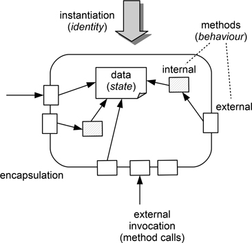
Figure 10.2: A simple illustration of object characteristics
We might also note that when modelling objects we will rarely need to model the use of global data and that the topological form of an application will usually be that of a network of objects rather than a hierarchical ‘tree’. (Objects may have a hierarchy, in fact, they can have more than one, but not quite in the same sense that we encountered with processes, where the hierarchy was usually one of invocation of functional elements.)
Moving on from what an object is, to thinking about how we can model it within the design process, we can identify some key object characteristics as follows.
Abstraction This plays an important role in the design process as a whole. It is concerned with describing the external perspective of an object in terms of its ‘essential features’. Abstraction provides a concise description of an object, which can then be used to help reason about its behaviour and about its relationships with other objects, without a need to possess any knowledge about its internal details.
Hence, when modelling objects, an essential property for any form of ‘design object’ is that it should be possible to identify its characteristics in an abstract manner. Identifying the key abstractions needed for an application and modelling their relationships is an important part of the design process.
Encapsulation The concept of information hiding is realised through the ability to conceal the details of an object's internal organisation and the ways in which information is represented through some form of encapsulation mechanism. Concealing the implementation details of an object makes it much easier to make changes to them without this having side-effects within the rest of the application. Encapsulation is an important issue for detailed design and implementation, and when thinking about this at a more abstract level the key question is to identify what should be concealed? Encapsulation and abstraction are largely complementary concepts.
Modularity This relates to the division of the overall architecture of an application into major sub-units (which we can consider as being motivated by ‘separation of concerns’). In doing so, one important criterion to consider is the complexity of the interfaces between the modules, while another is the likely effects of evolution of the application over time. For processes, the unit of modularity is the sub-program, which is largely organised around function, with relatively little emphasis being placed upon any relationships with data. In an object-oriented context where there are many forms of uses relationships, the choice of suitable modules becomes rather more complex and multi-faceted. For example, objects do not have a single thread of control, and it may be that the design of an application needs to allow different methods to be invoked concurrently, requiring that any consequent changes to variables be suitably protected.
The choice of modules is also determined by how the application will evolve. Where possible, we should be seeking to isolate major design decisions within separate modules, so that when changes do occur, they are largely isolated to a single module. We look at this later when we discuss the role of architectural patterns in Chapter 15.
Hierarchy As noted above, the object model is characterised by the presence of several different forms of hierarchical structure. Within an object that performs complex computations there is the possibility of having a hierarchy of function, rather similar to that of processes, whereby a complex task is sub-divided into small elements. There is also the possible use of a hierarchy based upon class structure, which is examined more fully in the rest of this section. Finally, there is the extent to which the interdependence of objects forms a hierarchy, usually referred to as the uses relationship, and this is explored more fully in the section that follows.
Before we examine the idea of a class hierarchy, there are two other characteristics of objects that should be mentioned, since they can affect the modelling process. The first is that new objects can be created at any time—and obviously, objects can be deleted too. This creates a dynamically changing application structure, and is a particularly useful feature when a particular object is mainly concerned with representing one item of a set of resources and we want to add new items to the set. However, it also represents a new issue in terms of the ideas about design models that we have so far encountered, since the equivalent feature for processes is limited to creating new list elements when using linked data structures. And a second, related characteristic, is that when a client issues a request to one object in a set of objects, it needs to be able to identify the object that should be the recipient (taking us back to the issue of objects having an identity).
10.1.2Objects and classes
Viewed in terms of their implementation roles, a class specification can be regarded as a form of ‘template’ that can be used to create objects. The class defines the state and behaviour attributes of an object, and when an object is created (instantiated) from a class, it acquires a set of variables and methods for that class. It also acquires a unique identity. However, that is not all, for depending upon how the object model is implemented, the class itself can provide some shared resources, visible to all of the objects derived from it. These may include class methods and class variables that do not form part of an object. For example, a class may keep a count of the objects created from it, using a class variable to store this, and employing class methods to increment/decrement the count. Figure 10.3 shows the class and object relationship in a schematic form. The key issue here is that the class data is essentially ‘in scope’ to the object in the same way as any object data.

Figure 10.3: Instantiating an object from its class
As an example, a simple form of this could be used in the CCC to limit the number of customers allowed to request a car at any point in time. Each ‘customer object’ can be linked to the details of up to three ‘car objects’, to provide the customer with a choice. However, it makes little sense to allow the same car to be offered to many customers at the same time. One way to constrain this would be for the ‘customer class’ to contain a counter and a condition that constrains the number of customer objects created at any point in time to be (say) half of the number of available cars. When this limit is reached, no further customers would be allowed to request a car. (Of course there would also need to be an accompanying mechanism to ‘queue’ requests from customers resulting in new customer objects.)
The hierarchy that is based upon class structure also leads us to consider the concept of inheritance, by which the properties of an object can be derived from the properties of other objects, or more correctly, of other classes. The question of how important inheritance is for object-oriented design comes close to being a theological issue. In particular, it introduces an issue that we will return to later, as to whether (or when) the ‘right’ design abstraction that should be used for modelling is the object or the class. So this is a good point to discuss the class/object relationship more fully.
In a programming language it is usually possible to create new data types from existing types, particularly by compounding these in some manner, or by defining a sub-range type. We can do much the same with classes, but the associated inheritance mechanism used to create subclasses is much more complex than the forms needed for creating derived types, since it needs to incorporate not just static data relationships, but also behavioural qualities (methods).
The subclasses of a class will share common structures and common features of behaviour. As an example, a bank may provide customers with a choice from many different forms of account, each of which may have different rules about how interest is calculated and paid, how charges are applied, the minimum balance required, overdraft rules and so on. However, all of these forms are clearly recognisable as being subclasses of some ‘parent’ class of bank_account, and share some common information structures (characteristics), such as those used to describe:
the current balance
the identity of the account holder
the date of creation for the account
as well as some common operations, such as:
creation of a new account
addition of interest
making a deposit
withdrawal of part of the balance
So, for this example, the class of bank_account will provide a description of these common properties and behaviour, while the detailed form of a particular subclass of account will be structured around the rules applying to that subclass. For design purposes, the designer therefore needs to concern themselves with the abstractions involved in the class (bank_account), and the subclasses. Figure 10.4 illustrates these points.

Figure 10.4: The inheritance hierarchy
Inheritance provides the mechanism by which subclasses acquire the general properties of their parent class(es) (also known as superclasses). In our example, any specific form of bank account will inherit the properties of bank accounts in general, but may have some features that only apply to that subclass (extended methods, additional methods, minimum balance etc.). So inheritance is an important constructional concept, and one that has been incorporated into many different programming languages.
The form depicted in Figure 10.4 is based upon the use of single inheritance, whereby a class can only inherit the properties of one superclass. (Of course, that superclass may itself inherit from a higher superclass.) However, it is also possible to inherit from more than one superclass, forming multiple inheritance. Obviously this does add considerably to the potential complexity involved in keeping track of the inheritance relationships. Hence many programming languages, most notably Java, only permit the use of single inheritance. From the point of modelling design ideas, multiple inheritance certainly increases the cognitive load involved, as well as adding to the technical debt by creating potential problems for future maintenance (Wood, Daly, Miller & Roper 1999).
A mechanism often introduced alongside inheritance is that of polymorphism. And like inheritance its use is apt to be associated with detailed design decisions, although conceptually at least, the decision to employ polymorphism could arise at any point. What it really relates to is the more flexible options that objects provide with regard to binding time.
When creating an application using a call-and-return form, the decision as to which sub-program is going to be called to perform some task is essentially fixed at the point when the code is written and compiled. The run-time process will contain the linkage information for that specific choice of sub-program, and this cannot be modified. So call-and-return architectures usually embody what we can regard as a static binding to particular sub-programs.
Figure 10.5 illustrates a very simple example of what can happen in an object-oriented system. In this example, there are three objects, designated X, Y and Z (which we can also assume are created from different classes). The block arrows indicate ‘makes use of’, so object X makes use of both other objects, while object Z makes use of object Y. Each object provides a set of methods that provide access to its encapsulated data. So, if object X needs to access data held by object Y, it might do so by using the methods Y.b() or Y.c() for that purpose. (Because objects have identity, it is a common convention to refer to a method as object_identifier.method_identifier.)

Figure 10.5: Dynamic binding and polymorphism
However, we might also note that object Z also provides a method b(). Since this can be referenced as Z.b(), no confusion need arise. However, in an object-oriented context, whenever object X makes a reference to the method b() with no object_identifier, we can expect that the context of that reference will be used to determine whether the appropriate method to use is Y.b() or Z.b(). And the decision about the appropriate choice will be made automatically and at run-time. This is because the bindings between objects are created dynamically when the application executes, allowing the appropriate choice to be made at that point.
It is this facility for selecting the appropriate method from a number of methods with the same identifier, but originating in different classes, that is termed polymorphism. (Strictly, although our example is couched in terms of objects, the methods themselves are defined in the parent classes.). To return for a moment to the earlier example of the bank account and its subclasses, we might expect that all classes will provide a withdraw() method, but that the detailed form of how this operates will be different, according to the type of account involved. So when this method is used in an application, the choice of which instantiation of withdraw() will be employed will depend upon the type of account provided as its argument. (This is also why we tend to associate polymorphism with inheritance, since inheritance provides a mechanism for exploiting this in an elegant manner.)
What is important here though is not the mechanism of polymorphism itself, but the way that it highlights the use of dynamic binding, and the characteristic that methods belong to objects, rather than being a static binding. From a design perspective, it also offers a quite radically different conceptual model.
The class-object relationship does complicate modelling and design in many ways, and not just through the use of such mechanisms as inheritance and polymorphism. Initial modelling may well be more problem-related, suggesting that the emphasis at that stage is likely to be upon objects. However, later stages of modelling, where constructional aspects become more important, may well use classes too.
10.2Relationships between objects
In the preceding section the emphasis was upon relationships that can occur between objects (and classes) that share attributes. In this section we examine the relationships that can exist between objects that are unrelated, but that need to work together in order to produce an application with the required behaviour and functionality.
A useful way of thinking about these and other relationships is to consider the different relationships that have been found to provide useful measures that can help with profiling the form of object-oriented applications. The set of six metrics identified by Chidamber & Kemerer (1994) (usually abbreviated to C&K) are widely used to assess the structures of these, and have themselves been derived from consideration of the object model. The metrics, together with their common acronyms are summarised in Table 10.1.
Metric |
Label |
Description |
|---|---|---|
Weighted Methods per Class |
WMC |
The sum of the ‘complexity’ values for all of the methods in a class. |
Depth of Inheritance Tree |
DIT |
A count of ‘tree height’ for ancestor classes. |
Number of Children |
NOC |
The number of subclasses that inherit from the given class. |
Coupling between Objects |
CBO |
The number of couples that exist between a class and other classes. |
Response for a Class |
RFC |
A measure of the “immediate surroundings of a class”. |
Lack of Cohesion in Methods |
LCOM |
The number of methods in a class that do not share attributes. |
These metrics provide surrogate measures for some of the object-oriented concepts (which inevitably are not easily measured directly). They are probably most usefully used for comparison, both between the properties of different classes, and also for the way that the properties of a particular class change as a result of maintenance. As metrics they are often used to help identify the classes that are considered to be most likely to contain faults. We discuss a systematic review of their usefulness for identifying modules likely to contain faults in Section 10.9, and for this section just provide brief comments that are based upon its findings (Radjenović, Hericko, Torkar & Živkovic 2013).
Two of the metrics (DIT and NOC) really belong with the discussion of the previous section, so we only need to comment here that while DIT probably offers no significant predictive ability for fault-proneness, NOC is in the group that does have “some ability to discriminate” with regard to the effect of changes to a class. NOC does give some indication of the potential influence that a class has on the design.
Two of the other metrics (WMC and LCOM) are calculated on a class basis, but are still useful when comparing values for different classes. Weighted Methods per Class (WMC) is calculated as:
where ci is the complexity of method i. The choice of the complexity measure c is left to the user, and essentially the metric calculates the overall complexity of the class as a function of the complexities of the individual elements. One choice for complexity is simply to set it to a value of 1, which produces a count of the methods in the class. Other values that are used include Lines of Code (LoC) and McCabe's Cyclomatic Complexity (which is a measure of the number of possible execution paths through a method). While WMC as a metric is of less use for making comparisons with other objects and classes, research does suggest that an increase in WMC after changes are made to a class is a good indicator of a possible increase in defects for that class.
Lack of Cohesion in Methods (LCOM) is based upon the idea that the elements of a class should be related to the purpose of the class, and hence should share some attributes. In an earlier version of the metric definitions, this was a count of methods that did not share variables, so that for a cohesive class we would expect a value of 0. This was later re-defined as follows:
which addresses the same concept more clearly. (Note though the comment about the validity of LCOM in the section on empirical evidence.)
The remaining two metrics are very much concerned with the interactions between objects (or classes).
Coupling between Objects (CBO) is the count of the number of couples that exist between a given class and other classes. Such a coupling is assumed to exist if one class uses methods or instance variables from another class, and an excessively high value of CBO is considered to be an indicator of poor modular design as well as an impediment to reuse. Coupling can take a range of forms: invocation of a method, inheritance, copying the value of a variable. The metric treats coupling as a two-way link, and so calculation of CBO needs to count both the classes that use a class and also those that it uses, as shown in the example of Figure 10.6.

Figure 10.6: Simple illustration of CBO measures
In the example, the solid lines indicate that one object calls methods in another (such as the line between class A and class B) while the dashed line between class A and class C indicates a different form of coupling, such as inheritance (class C inheriting from class A).
As often, the empirical findings about the usefulness of CBO are rather mixed, but overall, it was found to have “moderate predictive ability” with regard to fault-proneness. Two useful observations from a design perspective are that:
the presence of one class having a high value of CBO, while others have a CBO of 1, may indicate that a call-and-return design model has been mapped on to an object structure;
the presence of many classes with high CBO may indicate that the modularity in the design model is too granular, and that the classes are too small, requiring that they have to make use of other classes in order to perform their tasks.
Response for a Class (RFC) is a measure that seeks to reflect the influence of the “immediate surroundings of a class”, in other words, the methods that it uses directly. The response set of a class is the set of methods that are accessed by the set of methods belonging to an object of that class (which may include access to other methods within the class). This is a static measure, and so identifies the set of methods that might potentially be executed if a message is sent to one of the methods in an object of that class. It is defined as:
and Figure 10.7 shows a simple illustration of this.

Figure 10.7: Simple illustration of RFC measures
As a measure, the larger the number of methods that can be invoked from an object, the greater will be its complexity in terms of the effort needed to comprehend its operation, and of the level of understanding needed to test it.
There is limited research into the value of RFC, but what is available does indicate that this measure may correlate well with the likely number of defects in the class.
Of course, the things that we can measure (such as the C&K metrics) are not necessarily a guide to how we should design an application, and they are largely concerned with relatively static aspects of object relationships. However, the constructional viewpoint does play an important role in OO modelling, and so the measures do give some indication of the sort of relationships that we need to think about, and the issues that should perhaps be anticipated when producing a design model.
10.3Conceptual issues for object modelling
Figure 10.8 summarises some of the main characteristics of objects that have been mentioned in the preceding sections (obviously, they are not the only ones). Here we briefly look at the conceptual issues that are implied by these when thinking about how we can model object-oriented designs.

Figure 10.8: Key characteristics of an object
To model a design solution with the goal of employing any particular form of implementation (in this case objects), the designer needs to possess not only a good conceptualisation of the relevant architectural style, but also some clear cognitive mappings that can be used to link ideas about the design model to the implementation constructs that characterise that style. For the call-and-return style, the abstract model is one that is described in terms of statically linked sub-programs, with these having well-defined functional roles. The control and data topologies are also more or less the same, so that the task of mapping a design model on to a given procedural programming language is a relatively straightforward process. Likewise, the pipe-and-filter style employs fairly simple architectural elements, and again, both control and data topologies are closely linked, assisting with the eventual implementation.
When employing the object-oriented style, the basic concepts used for formulating the abstract design model, as well as for mapping it on to some form of implementation, are somewhat more challenging. To take a simple example, we noted earlier that observational studies of designers showed that they often ‘mentally executed’ their design models, to ensure that these exhibited the intended behaviour. This is a relatively straightforward exercise with a design model formulated using a style such as call-and-return, but a potentially much more complex task when realising a design using objects. The differing control and data topologies, together with dynamic binding of methods and multiple threads of execution within an object, all combine to make this more challenging.
One of the arguments sometimes made for adopting the object-oriented style is that it is more ‘natural’ than (say) call-and-return. Objects and their interactions can be recognised in the everyday world, whereas call-and-return uses a model which more closely reflects the workings of the computer itself. Hence (so the argument goes), the process of analysis should involve identifying the objects in the problem domain, and then use the resulting model to help with deciding upon a set of corresponding ‘solution objects’. However, in practice this has not proved to be a particularly effective strategy, and as Détienne (2002) observes:
which rather undermines the case for ‘naturalness’ and for any modelling based upon it. That said, Détienne also notes that comparative studies have demonstrated that:
object-oriented design tends to be faster and easier than the procedural (structured) design approaches discussed in Part III;
different designers will produce solutions that are more similar when using an object-oriented approach than when using other approaches;
suggesting that once the necessary levels of knowledge have been acquired by the designer, the object-oriented style may have more to offer.
An important issue here would appear to be the relatively steep learning curve involved in learning about object-oriented design. Studies by Fichman & Kemerer (1997), Vessey & Conger (1994) and Sheetz & Tegarden (1996) all observed that inexperienced designers struggled to acquire and deploy the concepts. In the study by Sheetz & Tegarden (1996), they specifically identified the following object-centred design issues as contributing to the problems by acting as sources of confusion for the inexperienced designer.
Organising the distribution of application functionality from the ‘problem space’ across a set of objects. (In other words, identifying the objects.)
Using the existing class hierarchy.
Designing classes (including making use of inheritance).
Using polymorphism, where the semantics of methods with the same name may differ.
Evaluating solutions (see earlier comment about mental execution).
Communication among objects.
Designing methods.
Some of this complexity relates largely to constructional issues, but much also arises from the cognitive load that is imposed by the need to comprehend and model so many issues at each step in design. The latter aspect will become more evident when we look at design processes in Part III. For the moment, we will concentrate on how we might model object-oriented properties.
10.4Object modelling: the issue of notations
Various forms of diagrammatical notation have been employed for modelling the different properties of objects. The best known of these is probably the UML (Rumbaugh, Jacobson & Booch 1999), mentioned earlier in the chapter. In his critique of the choices of visual notations used in modelling languages, Moody (2009) comments on the poor use of different shapes in many SE notations and observes that they “use a very limited repertoire of shapes, mostly rectangle variants” and goes on to point out that rectangles “are the least effective shapes for human visual processing” and that “curved, 3D, and iconic shapes should be preferred”.
Unfortunately, most OO notations, and the UML in particular, make extensive use of rectangles. Perhaps the one thing that we can say in their favour is that they are easily drawn on a whiteboard (one of the problems with both colour and icons is that they do present more of a challenge to sketching skills).

For the purposes of the rest of this chapter, rectangles have been retained where an established notational form is being used, but different shapes have been used as far as possible. Similarly, some examples have been sketched, for the reasons explained in Chapter 8. Specific forms from the UML are used explicitly where these have no obvious equivalents (for example, activity diagrams), but wherever possible, the following sections make use of fairly general forms of notation and syntax. It is worth noting that UML 2.0 uses a large set of diagrammatical forms (13), with some overlaps. However, only a key subset of these is described here and in later chapters!
10.5Modelling construction: the class diagram
The constructional viewpoint tends to play a rather different role for developing design ideas for objects than the one that it takes when producing design models based upon processes. In the latter case design models tend to be developed using the other viewpoints, and constructional forms are used at a relatively late stage in design (see Chapter 13). With the object model, the constructional viewpoint may well be used throughout the design process, probably because of the importance of identifying the key objects at an early stage. Early stages in design may use fairly simple descriptions of classes and objects, with more elaborate forms being used for detailed design.
Two aspects complicate description when employing the constructional viewpoint. Firstly there is the need to distinguish between a class and an object created from that class. And secondly, the designer has the added complexity of needing to model a number of quite different forms of uses relationship. This certainly complicates the role for any diagrammatical notation since, with relationships being ‘connectors’ between objects, it is likely to be more difficult to employ the sort of variety of visual shapes that can be adopted for the elements of a diagram. Equally, to understand and use a model, it is important to be aware of the nature of a particular relationship.
Classes themselves are usually modelled as rectangles. Early forms of OO design did use different shapes (for example, in Robinson (1992) a box with rounded corners was used for Hierarchical Object-Oriented Design (HOOD) objects. Since we spend a lot of time drawing objects when modelling, the choice of a simple rectangle is probably a practical one to employ, and it is of course easy to sketch.
The UML has adopted the use of a box in its class diagram, and classes can be represented using boxes with three compartments, two of which are optional. A class can simply be represented by a box containing the class name, which is probably sufficient when the class is first included in the model. The two optional compartments are the attributes, with the state of an object of the class at any time being determined by their values; and a list of the operations that the class provides through its methods. The resulting forms, using one, two or three compartments are shown in Figure 10.9. Since this is quite a flexible form, we will generally make use of it in the examples that follow.

Figure 10.9: The UML class notation
We might also note that the class diagram doubles up for the data-modelling role, largely because objects incorporate both methods and data.
10.5.1Distinguishing classes from objects
As explained earlier, the distinction between a class and an instantiation (object) created from that class can be quite important, particularly for those classes that may be used to create many objects. However, classes may often be used to create a single object, and so the distinction may well be one that can be ignored for much of the process of design.
However, since it can't be completely avoided, the question is then, how to make the distinction. The closeness of form between the two means that using different shapes is not really a practical way of making the distinction, and so this does tend to rely upon annotation. (Unfortunately, for the UML in particular, so do rather too many other features.)
The mechanism adopted in the UML is to give an object a name that is made up of the name of the specific object, followed by a colon, with this then being followed by the class name. The full name is then underlined, to emphasise that it is an object (this is particularly important with anonymous objects, since they simply have a name made up of the class name, preceded by a colon). So an object name (in the top compartment) may look like:
(It is also common practice to use the camelCase style for the object name, which may also help to make the distinction between an object and a class. A camelCase identifier is made up of several concatenated words, with all but the first word beginning with an uppercase letter.)
Underlining is probably a pragmatic option and certainly preferable to making use of typographical features such as bold, italics or other forms that are not easily sketched on a whiteboard. Figure 10.10 provides a very simple example of a class descriptor and an associated basic object descriptor. The compartments for status information and the key methods have been included for the example of the class descriptor, while the object descriptor just uses the basic compartment containing the identifier.

Figure 10.10: The UML class-object notations
The UML provides many options for supplying detail about status and operations for both classes and objects, including information about types, initial values and visibility. While possibly relevant for detailed design should it be required, these are unlikely to be useful while developing a design and so are not addressed here. More details about these features can be obtained from specialist texts on OO modelling such as (Arlow & Neustadt 2005) or (Lunn 2003).
10.5.2Class relationships
In order to make use of the class and object notations we need to be able to model the different relationships that can occur between them. These are generally drawn as one or more object diagrams that represent the structure of an application at some point in time. At its most basic an object diagram forms a network model that describes the interactions between a set of objects, where these interactions chiefly consist of method calls. (The UML refers to the links between classes as associations.)
In the same way that we employ the concept of arity with entity-relationship diagrams, when modelling relationships between classes it may be useful to indicate whether a relationship between two classes is on a one-to-one, one-to-many or many-to-many basis. The emphasis here is upon may. If the application consists of a small number of objects, with only one object from each class, there is little point in cluttering up the model with information about the multiplicity of the relationship.
Figure 10.11 illustrates the use of multiplicity for two simple examples from the CCC. The upper one indicates that a CCC site (assuming that CCC expand their business to other cities) can have between zero and many cars available. The lower one indicates that a car that is available can respond to any number of requests, but that the ‘search object’ for a customer may only select up to three cars.

Horrified purist

Figure 10.11: Use of class multiplicity annotation
The UML has some less than inspiring notations for indicating different forms of relationship between classes. However, it also provides the quite useful concept of a stereotype, which effectively allows a new modelling element to be introduced that is based upon an existing one. Stereotypes are created by placing the name of the stereotype between guillemots («…») and using it to label the line indicating the relationship. Although it might horrify a UML purist, using stereotypes as a means of clarifying intended relationships, especially when sketching, may be much clearer than using the graphical symbols defined in the UML.
When describing class–instance relationships we might therefore use the stereotype «instantiate». Another useful one is «use» (this one is so obvious that it can simply be treated as a default). The role of «create» is likewise obvious. Although not advocated by the UML, it may also be useful to use stereotypes for other relationships such as «inherit» and «aggregate». Reducing the number and complexity of symbols is a useful step when dealing with objects and doing so in this way reduces the cognitive load. It also demonstrates that you don't have to use the formal semantics of a notation, especially when sketching ideas.
Figure 10.12 shows the conventional UML notation for inheritance on the left, and the use of a stereotype on the right. There is definitely an argument in favour of using the stereotype for showing such a diagram to anyone unfamiliar with the UML, as well as when sketching on a whiteboard. However, one thing that can be harder to capture this way is the direction in which the ‘flow’ of inheritance should be read (although many might find the UML notation confusing anyway, in terms of the apparent ‘flow’ implied by the triangle). So careful positioning of the indexstereotype stereotype or using an additional arrowhead as shown here might sometimes be helpful.

Figure 10.12: UML class inheritance annotation versus using stereotypes
Other forms of association, including aggregation and composition can be used when modelling classes and objects. And of course, we can add polymorphism and abstract classes to our use of inheritance. All of this explains why books on modelling with the UML tend to be large—as classes and objects are much more complex design elements than processes. So, in fairness, while the UML itself may often be cumbersome as a modelling tool, it is required to provide ways of modelling some potentially very complex structures.
10.6Modelling behaviour: the statechart and the message sequence diagram
The idea of state plays a much bigger role for objects than it does for processes, not least because the use of encapsulation means that an object is very likely to contain persistent information related to its role and identity. And because an object can have many external methods, there can also be many ways of accessing and modifying that state.
Object modelling commonly makes use of two forms for modelling behaviour. The statechart (or ‘state diagram’) is used to model the way that the state of some entity (which may be an object, or a subsystem, or a complete application) is modified by interaction with the events occurring in the external world. And the message sequence diagram, or message sequence graph (MSG) can be used to model the way that events are triggered and handled over time. Actually, sequence diagrams are not entirely about behaviour, they can also be viewed as describing some aspects of function, highlighting the problem with any simple classification system! However, regardless of how we classify them, sequence diagrams (or sequence graphs; both terms are used) represent a useful modelling tool for thinking about the interactions that occur between objects.
10.6.1The statechart
Like the state transition diagram that was described in Section 9.3, the statechart is concerned with describing the behaviour of a ‘system’ as a form of finite-state automaton, or finite-state machine. Used at the system level it can be a good way of modelling the behaviour of reactive applications, responding to external events. Used at the object level, it can describe how an object responds to the requests created by its ‘response set’.
The statechart was devised by David Harel, and he has observed that it is based upon the more general mathematical concept of the higraph (Harel 1987, Harel 1988). It provides a rather more flexible modelling form than the STD, and in particular, it incorporates the facility for creating a hierarchy of abstractions. It also offers the facility to describe transitions that are orthogonal, in the sense that they can occur completely independently of each other, so making it possible to model transitions that can occur in parallel. And like the STD, it can be used to model the behaviour of a ‘problem’ (black box) as well as of a ‘solution’ (white box). The UML has largely adopted the form of statechart devised by Harel (but of course, not quite).
The original paper (1987) provides an excellent tutorial on statecharts and their powers of description. In this, the author uses the functions of a digital watch with two alarms to provide examples. Our examples here are somewhat less dramatic and extensive, but should provide essential ideas about how to use this form.
A state is denoted by a box with rounded corners, labelled with the name (identifier) for the state in the top of the box. Hierarchy is represented by encapsulating states within states, and directed arcs are used to represent a transition between states. The arcs are also labelled with a description of the event that triggers that transition, and optionally, with a parenthesised condition. (Conditions are quite common in the real world. For example, it might not be possible to engage a cruise control mechanism in a car—representing a change in its state—while the car is accelerating.)
Figure 10.13 uses a statechart to provide a very simple state model that describes the use of a car. At the top level it simply has two states that represent the car when the engine is off and when it is running. The default initial state is indicated by the short arrow with a black dot on the end. Transitions between these states are caused by pressing the starter (or waving a card) and by turning the ignition off. There are three sub-states when the engine is running. The initial state has the engine idling and no gear selected. To change to going forward we select a gear, and to stop we brake (OK, there are other ways, but this is a simplified diagram). Engaging reverse we have labelled the transition as ‘engage’ to emphasise that there is usually only one such gear, and again, stopping involves braking. And of course, there are no transitions between going forwards and reverse (again, this might be possible, but it is usually extremely unwise).

Figure 10.13: A simple statechart describing driving a car
This is a very simple model that wouldn't even be recommended for one's first driving lesson (it doesn't allow for slowing down and accelerating when moving forward as one example), but it is sufficient to show the essential ideas, and particularly the use of hierarchy.
Modelling watches and cars has the advantage that the events that cause transitions between states are directly identifiable in terms of button presses or using a gear lever. Figure 10.14 reworks the example provided in Figure 9.6, describing an air traffic system, to use a statechart formalism. (Some of the labels for the internal transitions have been omitted for clarity.)

Figure 10.14: A simple statechart describing an aircraft in an ATC system
When comparing this with the STD used in Figure 9.6, we can see that while the descriptions of state, event and transition are common to both, the STD provides a more detailed description in terms of the associated actions, while the statechart has more refined mechanisms for describing abstraction, defaults and scale. The lack of hierarchy limits the STD to being used to describe the behaviour of individual design elements, whereas the statechart can be used to describe complete systems through a hierarchy of diagrams and states. To some degree the strengths of the two forms are probably complementary, with the STD perhaps being more suited to modelling descriptions of ‘problems’ and the statechart being better suited to describing detailed ‘solutions’.
The remaining major feature of the statechart that should be described here is orthogonality. Our example here, shown in Figure 10.15, is rather more abstract in order to highlight the mechanisms involved.

Figure 10.15: Describing orthogonality in the statechart formalism
In our example, state ‘A’ can be described as being a superstate of two orthogonal states ‘B’ and ‘C’. These can in turn be described in terms of further states ‘D’ to ‘G’ but the two states involve what are essentially independent groupings. However, events may be common as can be seen from the description of the transitions that occur in response to event ‘a’. Also, in describing A, note that we need to identify the default entry to both states ‘B’ and ‘C’ (the inner states ‘D’ and ‘F’). There is also a conditional transition between states ‘F’ and ‘G’, where an event ‘b’ will cause a transition only if condition ‘P’ is satisfied.
The statechart is a powerful modelling tool for thinking about objects, and can also be used for modelling of executable use cases/scenarios (Harel & Gery 1997). Again, it is easily sketched on a whiteboard or on paper.
10.6.2The message sequence diagram
Sequence diagrams have proved to be particularly useful with object-oriented modelling. This is probably at least in part because they provide a means of modelling the interactions between different elements of a system, whether these be objects, actors, remote processes, or client and server. Since essentially they model collaboration, in this case object collaboration, they can be used with any architectural style that has loosely coupled elements.
Sequence diagrams can also be useful for modelling the interactions involved in a use case (or more correctly, in a specific scenario). Use cases have proved to be a useful tool for modelling object-oriented systems, so this tends to reinforce the value that they have for this type of modelling. The UML (inevitably) incorporates sequence diagrams, describing their form as follows.
A sequence diagram can be viewed as being a dynamic interpretation of a class model. It is concerned with how and in what order those elements in the class diagram interact, whereas the class diagram simply identifies that they do interact and collaborate. For this chapter at least, they have been categorised with the behavioural viewpoint because they essentially deal with interactions between objects (and really don't fit with any other viewpoint either). And like many behavioural forms, it is not hierarchical, and hence doesn't cope particularly well with large-scale patterns of interaction between many elements. And again, like other behavioural forms they can usefully be employed to describe ‘problems’ as well as ‘solutions’.
The organisation of a sequence diagram is dominated by the use of a timeline, which conventionally runs from the top of the page downwards. (Obviously, where there is a need to indicate the lapse of specific time intervals, such a diagram might be drawn to scale on the vertical axis, but generally only the sequential organisation is described. Each processing element, usually a class or object, or possibly some other system ‘actor’ is allocated a column and messages between them are shown as horizontal lines between the columns.
While the UML provides a very extensive and detailed syntax for modelling with sequence diagrams, it is worth noting that they are relatively easy to sketch and only need limited annotation. Indeed, they can be drawn with a quite minimal set of symbols. Figure 10.16 shows a simple example of a sequence diagram based upon drawing money from a ‘hole-in-the-wall’ bank machine. This shows a strength of the notation, in that it is easy to discuss whether or not this shows the ‘right’ distribution of tasks, or issues that have been omitted (such as what happens if the cash dispenser is empty). It also demonstrates a limitation, in that any sequence diagram used to describe a system model or a design model tends to illustrate just one use case/scenario (Ratcliffe & Budgen 2001). (In this role it is known as an ‘instance’ form of sequence diagram. There is also a ‘descriptor’ form that can be used for systems analysis and can be used for describing all possible scenarios. Since our main concern here is design, we focus on the instance form in this section.)

Figure 10.16: A simple example of a sequence diagram
Figure 10.17 shows a sequence diagram being used in what is more of a design role, and being used to model how a CCC member will perform the operation of selecting and accessing a car. So now the elements at the top of the time lines are classes (or objects) rather than external entities as in our previous example.

Figure 10.17: Designing with a sequence diagram
This also reflects a wider issue that the objects involved in this sequence must be appropriately related in the corresponding class diagram. Maintaining this form of consistency is a challenge, particularly during more detailed design activities.
10.7Modelling function: the activity diagram
One viewpoint where the UML does make a useful contribution to the set of notations is the functional viewpoint. UML activity diagrams can be used to model the way that a business operates and, like DFDs, can help with analysing the needs of a problem. (There are no really good notations for describing function when using objects. This is perhaps not surprising as unlike many processes, an object often doesn't have a single functional task.)
In particular, an activity diagram can be useful for modelling the type of ‘coordinating’ situation where a given computation cannot proceed until certain conditions are met (for example, new data is available and a prior computation has completed). The diagram does model states, but these now represent the performance of actions, and the focus of interest is upon what triggers transitions between the states. This emphasis upon action is why it has been categorised as functional here. However, rather as with sequence diagrams, an activity diagram can be viewed as providing a mix of functional and behavioural aspects in its description.
Some key notational elements are as follows.
The activity, which is a task performed by the application and is shown as a named box with rounded sides.
A state, which can be viewed as being an activity where nothing happens.
A transition, where work flows between activities, shown as an unlabelled arrow. The lack of a label is because, unlike the case of a statechart, the transitions arise from the actions of the activities themselves, not because of external events.
A decision, represented by a diamond, where a workflow divides between possible branches. When used, it is then necessary to label the transitions to indicate which condition is employed for a particular route.
The synchronisation bar is a thick horizontal line that represents the coordination of the activities. When all of the transitions into a bar are complete (the coordinating bit) then the outward transitions will be ‘fired’.
Entry and exit from a diagram are shown respectively by a short arrow with a filled dot on its tail, and a filled dot with a circle around it. There can only be one entry point, but there may be many exit points. This is illustrated in the sketch of the CCC booking process shown in Figure 10.18.

Figure 10.18: An activity diagram describing booking a car
Figure 10.19 uses the bank teller machine example to illustrate the use of synchronisation bars. One shows division of transitions (where multiple actions occur after a coordinating action, termed a fork), the second where an operation can only proceed after two transitions have completed (a join).
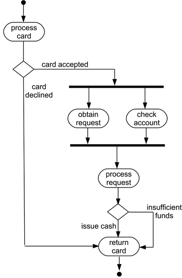
Figure 10.19: An activity diagram using synchronisation bars
10.8Use cases
This is a good point to discuss something that has been mentioned previously in this chapter, namely the idea of a use case.
The idea of the scenario describing a particular way that an application is used is one that has been employed informally over many years as a convenient description of, and way to think about, system behaviour. Ivar Jacobson made a valuable contribution to design modelling when he generalised this idea into that of a use case, formalising it as a tool for thinking about software design (Jacobson, Christerson, Jonsson & Overgaard 1992). Not surprisingly, his involvement in the formulation of the UML meant that use cases are a key element of this too.
We can draw an analogy between the relationship between a use case and a scenario and that of a program and a process executing on a computer. A program describes the rules for performing a set of possible actions, and a process comprises a particular instantiation of that program. Similarly, a use case represents a set of possible interactions between an application and other actors (where these can be devices, people, other pieces of software etc.), while a scenario will describe a particular sequence of these interactions.
A major attraction of employing use cases is the ability to document a set of user interactions with the application, and then to use the associated message sequences for a given system configuration to guide the design of an object model that will implement that application behaviour. Using a common abstraction to describe both behaviour and object model can help with the design modelling process.
The UML use case diagram expresses the idea of a use case at a fairly high level of abstraction. Figure 10.20 shows the basic elements of a use case diagram. The use case itself is shown as an oval, and represents “a logical description of a slice of system functionality” (Rumbaugh et al. 1999). Actors are (perhaps confusingly at times) usually represented by stick figures. Finally, there are four kinds of relationship shown in the figure, although two of these share a single representational form and hence need to be labelled with a stereotype in order to distinguish them. As we should note, the use case diagram is easy to sketch, and made even easier when designing because for most purposes, we only need the use case, actor and communication symbols.
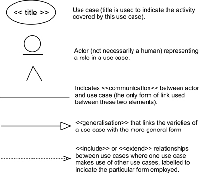
Figure 10.20: Elements of a UML use case diagram
Like other descriptive forms that are used with objects, the use case diagram is difficult to classify using the viewpoints model. The use case is concerned with the interactions that occur between a system and its environment, and hence can have a behavioural aspect. But they are also concerned with the tasks that an application performs, and so have a functional aspect in their role. (Since we can sometimes describe scenarios and use cases using message sequence diagrams, this mix is to be expected.)
Figure 10.21 shows a simple use case diagram for part of the CCC, again relating to the car reservation process.

Figure 10.21: Example of a UML use case diagram
In this model, the process of reserving a car involves four use cases, one to handle the initial request, another to negotiate the choice of a car, the third concerned with the user opening the car and finally depositing the car at the end of the session. The customer is an actor in all of these, while the billing subsystem is only an actor participating in the last two (when the customer actually claims and uses the car).
The UML use case diagram itself is largely concerned with the identification of use cases and the set of actors acting as participants in these. The means of creating a detailed specification of a use case is largely a matter of choice. It might involve the use of sequence diagrams, and possibly of some form of textual specification too. The latter might identify such aspects as the participating actors, pre-conditions for the use case to occur, details of actions involved and then post-conditions when the use case ends. Figure 10.22 provides a simple example for one of the use cases in Figure 10.21.

Figure 10.22: Example of a UML use case
The Unified Process (UP), described in Chapter 13, inevitably employs use cases, and they have been widely employed formally and informally. Use cases can also be related to the concept of the user story as employed in agile software development (Jacobson, Spence & Kerr 2016). They are not particularly dependent upon the use of an object-oriented architecture either, although they have made a particular contribution to applications of that form.
10.9Empirical knowledge about modelling objects and classes
This is a large chapter, and so this section has been organised around three important aspects of object-orientation that are described here. The first is the object model itself; the second is the different notations used for the UML; and the third relates to metrics used with objects.
10.9.1The object model
While classes and objects have a long history in software development, stemming back to the 1960s, and have been employed widely for that purpose, there is surprisingly little in the way of empirical studies related to designing applications using objects. A systematic mapping study examining this (Bailey, Budgen, Turner, Kitchenham, Brereton & Linkman 2007) found only 138 studies, with nearly half of these being concerned with metrics, 10 with the use of design patterns, and 19 with comparing the use of OO with non-OO forms. The most widely-used form was the laboratory experiment (arguably not the most effective tool for studying long-term design issues) with observational studies and case studies making up the form of empirical study for just under half of the papers found.
What that mapping study did not include was what we term experience papers and material from the grey literature. It may well be that these are used very widely to record design experiences in an informal manner.
Perhaps we should not be that surprised at the relatively small number of formal studies. There are even fewer studies looking at earlier forms of software architecture such as call-and-return, and the nature of design is such that making simple comparisons (such as call-and-return versus object-oriented) is a fairly pointless exercise. Questions that are more useful are going to be those relating to such issues as the relative ease of learning how to use different modelling forms (such as the study by (Vessey & Conger 1994), and guidance about how to use the different modelling approaches.
The systematic review by Tiwari & Gupta (2015) examines the evidence about the different roles performed by use cases. They found that use case specifications were typically employed for two perspectives. The first was for documenting functional requirements, while the second was for generating the lower-level software artifacts, particularly through model transformation.
10.9.2Object modelling notations
Essentially, the only widely documented source of object modelling notations is the UML. In addition to the analysis of visual notations by Moody (2009) which discusses many of the UML notations, there have been a number of studies looking at particular notations. The systematic review reported in (Budgen, Burn, Brereton, Kitchenham & Pretorius 2011) identified 49 studies, with metrics and comprehension being the two topics studied most extensively. Most studies were laboratory studies, with relatively few ‘field’ studies.
The subsequent survey by Petre (2013) also emphasised that the UML was not widely used in practice, although it was sometimes used for documentation. Of course, while the UML was not used formally, this does not rule out the possibility that its forms did influence the informal notations used by designers.
10.9.3Object-oriented metrics
The systematic review by Radjenović et al. (2013) looked at the value of different metrics for software fault prediction. It found that the Chidamber & Kemerer metrics were the most successful of the available OO metrics, with CBO, WMC and RFC being the most successful, while DIT and NOC were unreliable.
We might note here that from a measurement-theoretic perspective, LCOM is considered to be ‘theoretically invalid’ (Litz & Montazeri 1996), although from our perspective, it does identify a design property that may be important for objects. Kitchenham (2010) also observes that CBO is ‘flawed’ because it treats “forward and backward links as equivalent” arguing that these may not present equal difficulty of understanding, and hence have different influence upon likely faults. Again, from a design perspective, our main concern is the existence of such links, rather than their role.
Key take-home points about modelling objects and classes
Modelling the attributes of objects and classes uses a range of different forms to address the main viewpoints for each type of design element.
Objects are complex. The structures and properties of objects (and classes) are much more complex than those of processes, necessitating the use of more viewpoints together with the need to model a range of relationships as well as the elements.
Classes and objects. Both classes and objects are important design elements when developing design models—and there is no ‘right’ abstraction to employ for describing their properties in all circumstances. They can also be difficult to identify when creating the object model.
Relationships can have many forms. This aspect of object modelling can be challenging since there are many forms of relationship that can occur between objects, with properties that may need to be represented in different ways.
Learning to model objects is challenging. Studies suggest that object-oriented modelling is harder to learn than the use of simpler forms such as processes.
Modelling objects needs a mix of notations. The different characteristics require a mix of forms, and these also need to be kept consistent (a potentially useful role for tools).
Object notations make poor use of visual separation. Popular forms of diagrams, such as most of those used in the UML, tend to use a limited set of shapes and symbols, and make excessive use of shapes such as oblongs. The range of possible relationships adds to this, as it is even harder to devise distinct visual forms for these.