Chapter 15
Plan Production
So, you've toiled for days, weeks, or maybe months creating your design in the Autodesk® AutoCAD® Civil 3D® program, and now it's time to share it with the world—or at least your corner of it. Even in this digital age, paper plan sets still play an important role. You generate these sheets in Civil 3D using the Plan Production feature. This chapter takes you through the steps necessary to create a sheet set, including viewport planning, generating sheets, data management, and publishing.
In this chapter, you will learn to:
- Create view frames.
- Edit view frames.
- Generate sheets and review Sheet Set Manager.
- Create section views.
Preparing for Plan Sets
Plan Production tools enable you to quickly create sheet files by automating a process you have been doing manually for years. Creating layouts, creating and orienting your viewports, inserting and filling in title blocks, establishing external and data references, creating match lines, inserting north arrows, and setting up Sheet Set Manager are all menial but necessary tasks you must undergo in order to publish your design to paper. Before you can put Plan Production tools into action, you need to address some prerequisites. Let's examine those components first.
Prerequisite Components
The Plan Production feature uses several components to create a sheet set. This chapter will explore these elements in detail, but for now, we'll take a brief look at what the components are.
- Drawing Template Plan Production creates new layouts for each sheet in a plan set. To do this, the feature uses drawing templates with predefined layout tabs. These layout tabs contain a suitable border and up to two scaled viewports with configured types of plan, profile, or section.
For the exercises in this chapter, the default location for the final sheets will be
C:\Mastering\Ch15\FinishedSheetswww.sybex.com/go/masteringcivil3d2016) and place them in theC:\Mastering\Ch15 - Object and Display Styles Plan Production generates the following objects: view frames, view frame groups, match lines, and section sheets. Before creating plan sheets, you'll want to make sure you have styles set up for each of these objects. Section view group plot styles are associated with section sheet objects.
- Alignments and Profiles The Plan Production feature is used primarily for creating plan and profile views. For this to happen, your drawing must contain (or data reference) at least one alignment and profile. You must also have a sheet template ready with associated plan and profile viewports. You can produce plan-only or profile-only sheets if desired as long as you prepare a sheet template layout that supports single-plan or single-profile viewports. Plan Production tools cannot produce sheet files with two or more viewports of the same type.
- Sample Lines and Sections Creating section sheets requires an alignment, a sample line group, cross sections, a group plot style, and a sheet template with associated section viewports.
With these elements in place, you're ready to dive in and create some sheets. The general steps in creating a plan set are as follows:
- Meet the prerequisites listed previously.
- Create view frames.
- Create plan or plan-profile sheets.
- (Optional) Create section view groups.
- (Optional) Create section sheets.
- Manage the sheets using Sheet Set Manager.
- Plot or publish (hard copy or digitally).
The next sections describe this process in detail and the tools used in Plan Production. Sheet Set Manager, which is found in basic AutoCAD, is an integral part of this process.
Using View Frames and Match Lines
When you create sheets using the Plan Production tools, Civil 3D first automatically helps you divide your alignment into areas that will fit on your plotted sheet and display at the desired scale. To do this, Civil 3D creates a series of rectangular frames placed end to end (or slightly overlapping) along the length of alignment, like those in Figure 15.1. These rectangles are referred to as view frames and are automatically sized and positioned to meet your plan sheet requirements. This collection of view frames is referred to as a view frame group. Where the view frames overlap one another, Civil 3D creates match lines that establish continuity from frame to frame by referring to the previous or next sheet in the completed plan set. View frames and match lines are created in Model Space, using the prerequisite elements described in the previous section.
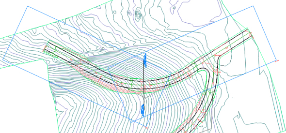
Figure 15.1 View frames and match lines
The Create View Frames Wizard

The first step in the process of creating plan sets is to generate view frames. Civil 3D provides an intuitive wizard that walks you through each step of the view frame creation process. Let's look at the Create View Frames Wizard and the various page options. After you've seen each page, you'll have a chance to put what you've learned into practice in an example.

From the Output tab ![]() Plan Production panel, choose Create View Frames to launch the Create View Frames Wizard (Figure 15.2). The wizard consists of several pages. A list of these pages is shown along the left sidebar of the wizard, and an arrow indicates which page you're currently viewing. You move among the pages using the Next and Back navigation buttons along the bottom of each page. Alternatively, as with all wizards, you can jump directly to any page by clicking its name in the list on the left. The following sections walk you through the pages of the wizard and explain their features.
Plan Production panel, choose Create View Frames to launch the Create View Frames Wizard (Figure 15.2). The wizard consists of several pages. A list of these pages is shown along the left sidebar of the wizard, and an arrow indicates which page you're currently viewing. You move among the pages using the Next and Back navigation buttons along the bottom of each page. Alternatively, as with all wizards, you can jump directly to any page by clicking its name in the list on the left. The following sections walk you through the pages of the wizard and explain their features.
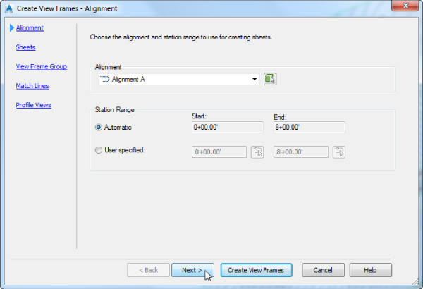
Figure 15.2 The Create View Frames – Alignment wizard page
Create View Frames – Alignment Page
You use the first page of the Create View Frames Wizard (shown previously in Figure 15.2) to select the alignment and station range along which the view frames will be created.
- Alignment In the top area of this page, you select the alignment along which you want to create view frames. You can either select it from the drop-down list or click the Select From The Drawing button to select the alignment onscreen.

- Station Range In the Station Range area of the page, you define the station range over which the frames will be created. Selecting Automatic creates frames from the alignment start to the alignment end. Selecting User Specified lets you define a custom range, either by keying start and end station values in the appropriate box or by clicking the button to the right of the station value fields and graphically selecting the station from the drawing.
An example of when you would want to select specific stations is if you have a subdivision that will be constructed in phases. You have designed an entire roadway but need to only create specific sheets for a specific phase.
Create View Frames – Sheets Page
You use the second page of the Create View Frames Wizard (Figure 15.3) to establish the sheet type and the orientation of the view frames along the alignment. A plan production sheet is a layout tab in a drawing file. To create the sheets, Civil 3D references a predefined drawing template (with the filename extension .dwt
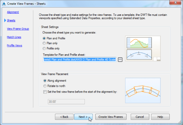
Figure 15.3 Create View Frames – Sheets wizard page
Sheet Settings
The Plan Production feature provides options for creating three types of sheets:
- Plan And Profile This option generates a sheet with two viewports; one viewport shows a plan view, and the other shows a profile view of the section of the selected alignment segment.
- Plan Only As the name implies, this option creates a sheet with a single viewport showing only the plan view of the selected alignment segment.
- Profile Only Similar to Plan Only, this option creates a sheet with a single viewport, showing only the profile view of the selected alignment segment.
After choosing the sheet type, you must define the template file and the layout tab within the selected template that Civil 3D will use to generate your sheets. Several predefined templates ship with Civil 3D and are part of the default installation. Be sure to choose the sheet type before selecting the template so that layouts associated with that sheet type will be displayed and selectable. Follow these steps:
- Click the ellipsis button on this page to display the Select Layout As Sheet Template dialog, shown in Figure 15.4.
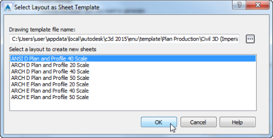
Figure 15.4 Use the Select Layout As Sheet Template dialog to choose which layout you would like to apply to your newly created sheets.
This dialog provides the option to select the DWT file and the layout tab within the template.
- Click the ellipsis button in the Select Layout As Sheet Template dialog to browse to the desired template location.
Typically the default template location is:
C:\Users\<username>\AppData\Local\Autodesk\C3D 2016\enu\Template\Plan Production\Alternatively, if you are working in a network environment, your templates can be kept in a common folder on the network.
After you select the template you want to use, a list of the layouts that contain the appropriate viewports contained in the DWT file appears in the Select Layout As Sheet Template dialog.
- Choose the appropriate layout.
Notice that in the template selected (see Figure 15.4) there are layouts for various sheet sizes as well as various scales that are included in the Plan Production templates that ship with Civil 3D.
View Frame Placement
Your view frames can be placed in one of two ways: either along the alignment or rotated to north. Use the bottom area of the Sheets page of the wizard to establish the placement.
- Along Alignment This option aligns the long axes of the view frames parallel to the alignment. Refer to the graphic to the right of the radio buttons in the dialog for a visual representation. This graphic is shown at the left in Figure 15.5.

Figure 15.5 View Frame Placement shown using the Along Alignment option (left) and the Rotate To North option (right)
- Rotate To North As the name implies, this option aligns the view frames so they're all rotated to the north direction, regardless of the changing rotation of the alignment centerline. North here is synonymous with the True North according to the world coordinate system. This graphic is shown at the right in Figure 15.5.
Set The First View Frame Before The Start Of The Alignment By
Regardless of the view frame placement you choose, you have the option to place the first view frame some distance before the start of the alignment. The Set The First View Frame Before The Start Of The Alignment By option is useful if you want to show a portion of the site, such as an existing offsite road, in the plan view. When this option is selected, the text box becomes active, letting you enter the desired distance.
Create View Frames – View Frame Group Page
You use the third page of the Create View Frames Wizard (Figure 15.6) to define creation parameters for your view frames and the view frame group to which they'll belong. The page is divided into two areas: the top for the view frame group and the bottom for the view frames themselves.
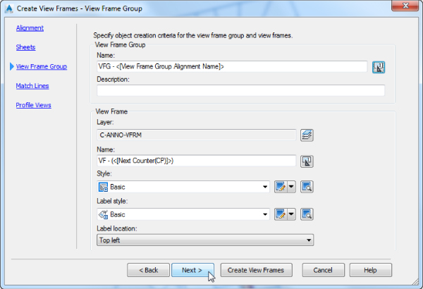
Figure 15.6 Create View Frames – View Frame Group wizard page
- View Frame Group Use this area of the View Frame Group page to set the name and an optional description for the view frame group. The name can consist of manually entered text, text automatically generated based on the Name template settings, or a combination of both.
- View Frame Use this area of the View Frame Group page to set various parameters for the view frames, including the layer for the frames, view frame names, view frame object and label styles, and label location. Each view frame can have a unique name (using an incremental counter), but the other parameters are the same for all view frames. Note that it is a good practice to modify these in the feature and command settings of your template so they are the default values used every time you run the command.

- Layer This option defines the layer on which the view frames are created. This layer is defined in the Drawing Settings dialog, but you can override it by clicking the Layer button and selecting a different layer. Setting the view frame layer to No-Plot will ensure that your drawing does not end up plotting with unwanted rectangles.
- Name The Name setting is nearly identical in function to that of the View Frame Group Name setting discussed earlier. With the settings shown previously in Figure 15.6, the default naming results would be VF – (1), VF – (2), and so on.
- Style Like nearly all objects in Civil 3D, view frames have styles associated with them. The view frame style is simple, with only one component: the view frame border. You use the drop-down list to select a predefined style.
- Label Style Also like most other Civil 3D objects, view frames have label styles associated with them. And like other label styles, the view frame labels are created using the Label Style Composer and can contain a variety of components.
- Label Location The last option on this page lets you set the label location. The default feature setting places the label at the top left of the view frame.
For view frame labels placed at the top of the frame, the term top is relative to the frame's orientation. For alignments that run left to right across the page, the top of the frame points toward the top of the screen. For alignments that run right to left, the top of the frame points toward the bottom of the screen.
Create View Frames – Match Lines Page
You use the fourth page of the Create View Frames Wizard (Figure 15.7) to establish settings for match lines. Match lines are used to maintain continuity from one sheet to the next. They're typically placed at or near the edge of a sheet, with instructions like “See Sheet XX” for continuation.
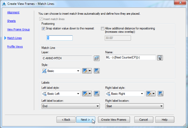
Figure 15.7 Create View Frames – Match Lines: page
- Insert Match Lines You have the option to automatically insert match lines. Match lines are used only for plan views, so if you're creating Plan And Profile or Plan Only sheets, the option is automatically selected and can't be deselected.
- Positioning Use this area of the Match Lines page to define the initial location of the match lines and provide the ability to later move or reposition the match lines.
- Snap Station Value Down To The Nearest By selecting this option, you override the drawing station settings and define a rounding value specific to match line placement. With the settings shown previously in Figure 15.7, a value of 1 is entered, resulting in the match lines being placed at the nearest whole station. For example, if the station was 8+14.83 and the value was 1, it would round down to 8+14, but for the same station, if the value was set to either 50 or 100, it would round down to 8+00.
This feature always rounds down (snap station down as opposed to snap station up). The exception to this is that if the rounding would put the match line at an undesirable location (such as before the previous match line or before the beginning of the alignment), then no rounding would be performed and the calculated station would be used.
- Allow Additional Distance For Repositioning (Increases View Overlap) Selecting this option activates the text box, allowing you to enter a distance by which the views on adjacent sheets will overlap and the maximum distance that you can move a match line from its original position within the overlap area. While the match line locations are originally created automatically, there are going to be instances when you will want to move the match line if it bisects a critical location. Any value entered will decrease the station range between match lines.
- Snap Station Value Down To The Nearest By selecting this option, you override the drawing station settings and define a rounding value specific to match line placement. With the settings shown previously in Figure 15.7, a value of 1 is entered, resulting in the match lines being placed at the nearest whole station. For example, if the station was 8+14.83 and the value was 1, it would round down to 8+14, but for the same station, if the value was set to either 50 or 100, it would round down to 8+00.
- Match Line Use this area of the Match Lines page to provide the settings for the match line. This area is similar to those for view frames on the previous page of the wizard. You can define the layer, the name, and the style.
With the settings shown previously in Figure 15.7, the match lines will be named using a predefined text (ML –) and a next counter: ML – (1), ML – (2), ML – (3), and so on.
- Labels The options in this area of the Match Line page are also similar to those for view frames. Different label styles are used to annotate match lines located at the left and right sides of a frame. This lets you define match-line label styles that reference either the previous or next station adjacent to the current frame. You can also set the location of each label independently using the Left and Right Label Location drop-down lists. You have options for placing the labels at the start, end, or middle of the match line or at the point where the match line intersects the alignment.
With the settings shown previously in Figure 15.7, the label style for use at the left match line is shown in Figure 15.8. This Basic Left label style uses the Match Line Number, Match Line Station value, and Previous Sheet Number.

Figure 15.8 An example match line label style
Create View Frames – Profile Views Page
The final page of the Create View Frames Wizard (Figure 15.9) is optional and will be disabled and skipped if you chose to create Plan Only sheets on the Sheets page of the wizard. Use the drop-down lists to select both the profile view style and the band set style. These styles will be discussed in Chapter 19, “Object Styles.”
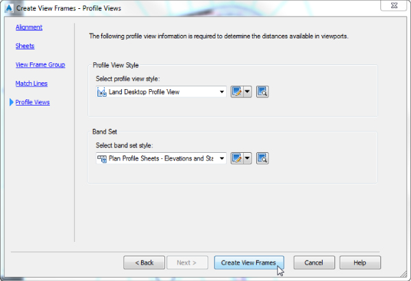
Figure 15.9 Create View Frames – Profile Views wizard page
Civil 3D Plan Production tools use the settings in the profile view style and band styles to determine placement of the profile view in the viewport, sometimes disregarding station labels below the profiles. For that reason often it is necessary to force the program to boost the profile view higher in the viewport by adding a “white space” band. This would be an invisible band of a certain height. Even though you can't see the band, Civil 3D provides space for it in the viewport.
This last page of the wizard has no active Next button since this is the last page. Complete the creation of the view frames by clicking the Create View Frames button.
Creating View Frames
Now that you understand the wizard pages and available options, you'll try them in this exercise:
- Open the
1501_ViewFrameWizard.dwg1501_ViewFrameWizard_METRIC.dwgwww.sybex.com/go/masteringcivil3d2016.)This drawing contains several alignments and profiles as well as styles for view frames, view frame groups, and match lines.
- To launch the Create View Frames Wizard, from the Output tab
 Plan Production panel, choose Create View Frames.
 - On the Alignment page, do the following:
- Select Frontenac Drive from the Alignment drop-down list.
- For Station Range, verify that Automatic is selected.
- Click Next to advance to the next page.
- On the Sheets page, do the following:
- In the Sheet Settings area, select the Plan And Profile option.
- Under Template For Plan And Profile Sheet, click the ellipsis button to display the Select Layout As Sheet Template dialog.
- In the Select Layout As Sheet Template dialog, click the ellipsis button and browse to the templates in the chapter folder:
C:\Mastering\Ch15\ - Select the template named
MasteringPandPTemplate.dwtMasteringPandPTemplate_Metric.dwtA list of the layouts in the DWT file appears in the Select Layout As Sheet Template dialog.
- Select the layout named ARCH D Plan And Profile 20 Scale (or ISO A1 Plan and Profile 1 to 500 for metric users) and click OK to dismiss the Select Layout As Sheet Template dialog.
- In the View Frame Placement area, select the Along Alignment option.
- Select the Set The First View Frame Before The Start Of The Alignment By option.
Note that the default value for this particular drawing is 30′ (or 10 m for metric users).
- Click Next to advance to the next page.
- On the View Frame Group page, confirm that all settings are as follows (these are the same settings shown previously in Figure 15.6) and then click Next to advance to the next page:
Setting Value View Frame Group Name VFG – <[View Frame Group Alignment Name(CP)]> – (<[Next Counter(CP)]>) View Frame Name VF – (<[Next Counter(CP)]>) Style Basic Label Style Basic Label Location Top Left - On the Match Lines page, confirm that all settings are as follows (these are the same settings shown previously in Figure 15.7) and then click Next to advance to the next page:
Setting Value Snap Station Value Down To The Nearest 1 Layer C-ANNO-MTCH Name ML – (<[Next Counter(CP)]>) Style Basic Left Label Style Basic Left Left Label Location End Right Label Style Basic Right Right Label Location Start - On the Profile Views page, confirm that the settings are as follows (these are the same settings shown previously in Figure 15.9) and then click Create View Frames:
Setting Value Select Profile View Style Land Desktop Profile View Select Band Set Style Plan Profile Sheets – Elevations And Stations
The view frames and match lines are created, as shown in Figure 15.10.
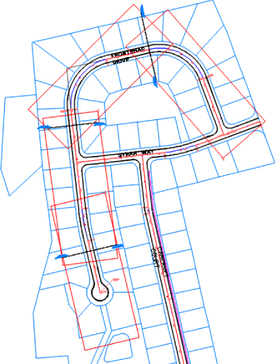
Figure 15.10 Finished view frames and match lines in the drawing
Because of the sheet sizes and scales, the Imperial drawing in this example generates four view frames, while the metric drawing generates only two view frames.
When this exercise is complete, you can close the drawing. A saved copy of this drawing is available from the book's web page with the filename 1501_ViewFrameWizard_FINISHED.dwg1501_ViewFrameWizard_METRIC_FINISHED.dwg
Editing View Frames and Match Lines
After you've created view frames and match lines, you may need to edit them. Edits to some view frame and match line properties can be made via the Prospector tab in the Toolspace palette by expanding the View Frame Groups branch, as shown in Figure 15.11.
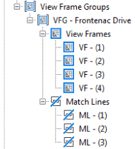
Figure 15.11 View Frame Groups in Prospector
You can change some information in the Preview area of Prospector when you highlight either the View Frames branch or the Match Lines branch. Alternatively, you can make further edits from the View Frame Properties dialog or the Match Line Properties dialog. One way of accessing these dialogs is through the View Frame contextual tab or the Match Line contextual tab. Another method is by right-clicking the desired object in Prospector and selecting Properties. For both view frames and match lines, you can change the object's name or style only via the Information tab in their Properties dialog. All other information displayed on the other tabs is read-only.
You make changes to geometry and location graphically using special grip edits (Figure 15.12). Like many other Civil 3D objects with special editing grips (such as profiles and pipe network objects), view frames and match lines have editing grips you use to modify the objects' location, rotation, and geometry. Let's look at each separately.
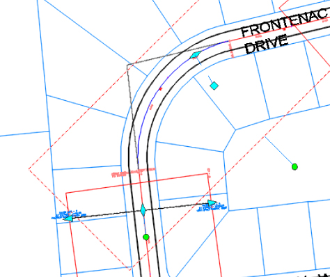
Figure 15.12 View frame and match line grips
View frames can be graphically edited in three ways. Once you select a view frame object (the rectangular object selected at the top portion of the image in Figure 15.12), you can move it, slide it along the alignment, and rotate it as follows:
- To Move a View Frame The standard square grip is used for most typical edits, including moving the object.
- To Slide a View Frame The diamond-shaped grip along the alignment at the center of the frame lets you move the view frame in either direction along the alignment while maintaining the orientation (Along Alignment or Rotated North) you originally established for the view frame when it was created.
- To Rotate a View Frame The circular handle grip works like the one on pipe-network structures. Using this grip, you can rotate the frame around its center.
Also, selecting multiple objects and then selecting their grips while holding Shift makes each grip “hot” (usually a red color). This allows you to grip-edit one object and all of the “hot” objects will also experience the same grip edit, like sliding a group of view frames along the alignment.
You can edit a match line's location and length using special grips. As with view frames, you can slide them along the alignment and rotate them. They can also be lengthened or shortened. Unlike view frames, they can't be moved to an arbitrary location. Once you select a match line object (the object selected on the lower side of Figure 15.12), you can edit it as follows:
- To Slide a Match Line The diamond-shaped grip at the center of the match line lets you move the match line in either direction along the alignment while maintaining the orientation (Along Alignment or Rotated North) that you originally established for the view frame.
Note that the match line can be moved in either direction only a distance equal to or less than that entered on the Match Line page of the wizard at the time the view frames were created. For example, if you entered a value of 50′ (15 m) for the Allow Additional Distance For Repositioning option, your view frames are overlapped 50′ (15 m) to each side of the match line, and you can slide the match line only 25′ (15 m) in either direction from its original location. Unless you move the view frame, then those extents will be the new maximum move distance.
- To Rotate a Match Line The circular handle grip enables you to rotate the match line just as you can with the circular handle grip on a view frame.
- To Change a Match Line's Length When you select a match line, a triangular grip is displayed at each end. You can use these grips to increase or decrease the length of each half of the match line. For example, moving the grip on the top end of the match line changes the length of only the top half of the match line; the other half of the match line remains unchanged. See the sidebar “Don't Forget Your AutoCAD Functions!” for tips on using AutoCAD features. If you select a match line, click one of the triangular grips, and then hold Shift and select the other triangular grip, the match line will shorten on one end as you lengthen the other end, and vice versa.
The following exercise lets you put what you've learned into practice as you change the location and rotation of a view frame and change the location and length of a match line:
- Open the
1502_EditViewFramesAndMatchLines.dwg1502_EditViewFramesAndMatchLines_METRIC.dwg - Confirm that Dynamic Input is enabled; if it is not, press F12.
- Select the view frame, which consists of stations 9+56 to 14+34 (or 0+267 to the end for metric users), and select its diamond-shaped sliding grip.
- Slide this diamond grip so the overlap with the lower view frame isn't so large. Either graphically slide it to station 11+00 (or 0+360 for metric users) or enter 1100 ↲ (360 ↲ for metric users) in the Dynamic Input text box.
- Press Esc to clear your selection.
- Select the view frame, which consists of stations 14+34 to the end (or 0+267 to the end for metric users), and select the circular rotation grip.
- Rotate the view frame slightly to better encompass the road. Enter 8 ↲ (268 ↲ for metric users).
- Press Esc to clear your selection of the view frame.
Next, you will adjust the match line's location.
- Select the match line, which is currently at station 14+34 (or 0+267 for metric users), and then select its diamond sliding grip.
- Either graphically slide it to station 13+25 (or 0+250 for metric users) or enter 1325 ↲ (250 ↲ for metric users) in the Dynamic Input text box.
Notice that the match line label is updated with the revised station.
Next, you'll adjust the length of the match line to fit within the view frame extents.
- Select the triangular lengthen grip at the west end of the match line, and either graphically shorten it to 75′ (or 50 m for metric users) or enter 75 ↲ (or 50 ↲ for metric users) in the Dynamic Input text box.
- Select the triangular lengthen grip at the east end of the same match line, and either graphically shorten it to 75′ (or 50 m for metric users) or enter 75 ↲ (or 50 ↲ for metric users) in the Dynamic Input text box.
- Press Esc to clear your selection.
When this exercise is complete, you can close the drawing. A saved copy of this drawing is available from the book's web page with the filename 1502_EditViewFramesAndMatchLines_FINISHED.dwg1502_EditViewFramesAndMatchLines_METRIC_FINISHED.dwg
Now that you have generated the view frames and match lines in the drawing and you have placed them where you want them, let's look at using these objects to generate sheets.
Creating Plan and Profile Sheets
The Plan Production feature uses the concept of sheets to generate the pages that make up a set of plans. Simply put, sheets are layout tabs with viewports showing a given portion of your design model, based on the view frames previously created. The viewports have special viewport properties set that define them as either plan or profile viewports. These viewports must be predefined in a drawing template (DWT) file to be used with the Plan Production feature. You manage the sheets using the standard AutoCAD Sheet Set Manager feature.
The Create Sheets Wizard
After you've created view frames and match lines, you can proceed to the next step of creating sheets. Like view frames, sheets are created using a wizard. Let's look at the Create Sheets Wizard and the various page options. After you've seen each page, you'll have a chance to put what you've learned into practice in an example.

From the Output tab ![]() Plan Production panel, you launch the Create Sheets Wizard by choosing Create Sheets. As with the Create View Frames Wizard, a list of the Create Sheets Wizard's pages is shown along the left sidebar, and an arrow indicates which page you're currently viewing. You move among the pages using the Next and Back navigation buttons along the bottom of each page. Alternatively, you can jump directly to any page by clicking its name in the list on the left. The following sections walk you through the pages of the wizard and explain their features.
Plan Production panel, you launch the Create Sheets Wizard by choosing Create Sheets. As with the Create View Frames Wizard, a list of the Create Sheets Wizard's pages is shown along the left sidebar, and an arrow indicates which page you're currently viewing. You move among the pages using the Next and Back navigation buttons along the bottom of each page. Alternatively, you can jump directly to any page by clicking its name in the list on the left. The following sections walk you through the pages of the wizard and explain their features.
Create Sheets – View Frame Group And Layouts Page
You will use the first page of the Create Sheets Wizard (Figure 15.13) to select the view frame group for which the sheets will be created. It's also used to define how the layouts for these sheets will be generated and which sheets will be created (all or a range).
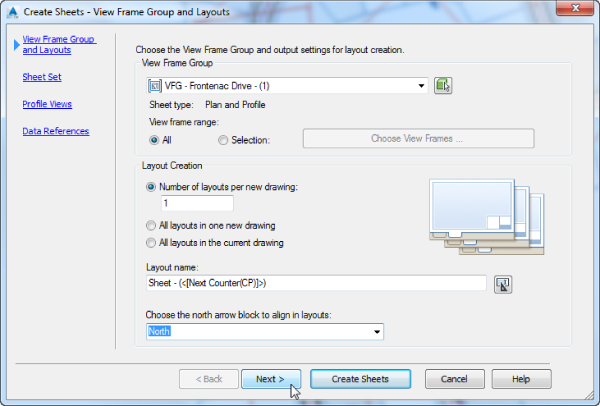
Figure 15.13 Create Sheets – View Frame Group And Layouts wizard page
- View Frame Group In the top area of this page, you select the view frame group. You can either select it from the drop-down list or click the Select From The Drawing button to select the view frame group onscreen. After you've selected the group, you use the View Frame Range option to create sheets for all frames in the group or only for specific frames of your choosing.
- All Select this option when you want sheets to be created for all view frames in the view frame group.
- Selection Select this option to activate the Choose View Frames button. Click this button to display the Select View Frames dialog, where you can select specific view frames from a list. You can select a range of view frames by using the standard Windows selection technique of clicking the first view frame in the range and then holding Shift while you select the last view frame in the range. You can also select individual view frames in nonsequential order by holding Ctrl while you make your view frame selections. Figure 15.14 shows two of the four view frames selected in the Select View Frames dialog.
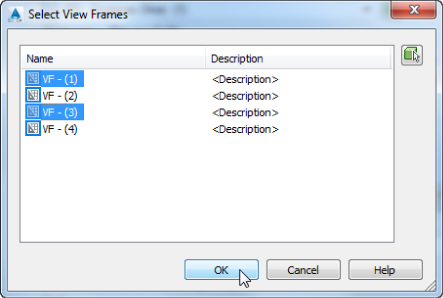
Figure 15.14 Select view frames by using standard Windows selection techniques.
- Layout Creation In this area, you define where and how the new layouts for each sheet are created as well as the name format for these sheets and information about the alignment of the north arrow block.
There are three options for creating layout sheets: The layouts are created in multiple new drawing files (with a limit to the maximum number of layout sheets created in each file), all the new layouts are created in a new drawing file, or all the layout tabs are created in the current drawing (the drawing you're in while executing the Create Sheets Wizard).
- Number Of Layouts Per New Drawing This option creates layouts in new drawing files and limits the maximum number of layouts per drawing file to the value you enter in the text box. For best performance, Autodesk recommends that a drawing file contain no more than 10 layouts. On the last page of this wizard you're given the option to select the objects for which data references will be made. These data references are then created in the new drawings.
- All Layouts In One New Drawing As the name implies, this option creates all layouts for each view frame in a single new drawing. Use this option if you have fewer than 10 view frames, to ensure best performance. If you have more than 10 view frames, the previous option is recommended. On the last page of this wizard you're given the option to select the objects for which data references will be made. These data references are then created in the new drawing.
- All Layouts In The Current Drawing When you choose this option, all layouts are created in the current drawing. You need to be aware of two scenarios when working with this option. (As explained later in Chapter 16, “Advanced Workflows,” you can share a view frame group via data shortcuts and link it to other drawings as a data reference.)
- When creating sheets, it's possible that your drawing references the view frame group from another drawing (rather than having the original view frame group in your current drawing). In this case, you're given the option to select the additional objects for which data references will be made (such as alignments, profiles, pipes, and so on). These data references are then created in the current drawing. You select these objects on the last page of the wizard.
- If you're working in a drawing where the view frames were created (therefore, you're in the drawing in which the view frame group exists), the last page of this wizard is disabled. This is because in order for you to create view frames (and view frame groups), the alignment (and possibly the profile) must either exist in the current drawing or be referenced as a data reference (recall the prerequisites for creating view frames, mentioned earlier).
- Layout Name Use this text box to enter a name for each new layout. As with other named objects in Civil 3D, you can use the Name template to create a name format that includes information about the object being named. With the settings shown previously in Figure 15.13, the layouts will be named using a predefined text (Sheet –) and the next counter: Sheet – (1), Sheet – (2), Sheet – (3), and so on. Using the Name template, you could alternatively use the Parent Drawing Name, View Frame Start/End Raw Station, View Frame Start/End Station Value, View Frame Group Alignment Name, and View Frame Group Name options.
- Choose The North Arrow Block To Align In Layouts If the template file you've selected contains a north arrow block, it can be aligned so that it points north on each layout sheet. The block must exist in the template and be located in the layout. If there are multiple blocks, select the one you want to use from the drop-down list.
Create Sheets – Sheet Set Page
You use the second page of the Create Sheets Wizard (Figure 15.15) to determine whether a new or existing sheet set (with the filename extension .dst.dst.dwg
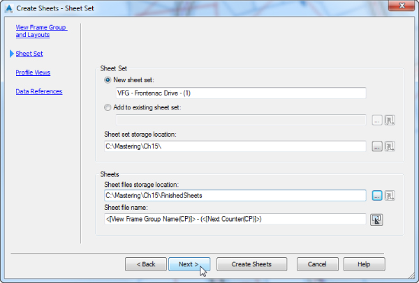
Figure 15.15 Create Sheets – Sheet Set wizard page
- Sheet Set In the Sheet Set area of the page, you select whether to create a new DST file or add the sheets created by this wizard to an existing DST file.
- New Sheet Set Selecting this option allows you to generate a new sheet set. In the text box, you can enter a name for the sheet set or accept the name that is generated for you.
- Add To Existing Sheet Set Selecting this option enables you to add to a sheet set that has already been generated. Click the ellipsis button to browse to the location of the DST file. If you are working in a Vault project, you can click the Vault button to browse to the file in the vault project. If Autodesk Vault is not installed, the Vault button will be inactive.
- Sheet Set Storage Location This text box is active only if you have selected New Sheet Set. When it's active, you can type the path to the folder where the DST file will be created or you can use the ellipsis to browse to the storage location. If you are working in a vault project, you can click the Vault button to browse to the storage location in the vault project. If Autodesk Vault is not installed, the Vault button will be inactive.
- Sheets This area is active only if you are creating layouts in new drawings. If you choose to create layouts in the current drawing, the area will be inactive.
- Sheet Files Storage Location Type the path to the folder where the sheet files will be created, or you can use the ellipsis to browse to the storage location. If you are working in a vault project, you can click the Vault button to browse to the storage location in the vault project. If Autodesk Vault is not installed, the Vault button will be inactive.
- Sheet File Name As with many of the previous names, you can use a Name template to specify how the name for the sheet file is generated. With the settings shown previously in Figure 15.15, the sheet files will be named using the View Frame Group Name entry and the next counter in parentheses. Using the Name template, you could alternatively use the Parent Drawing Name, View Frame Start/End Raw Station, View Frame Start/End Station Value, and View Frame Group Alignment Name options.
Create Sheets – Profile Views Page
The third page of the Create Sheets Wizard (Figure 15.16) lists the profile view style and the band set selected in the Create View Frames Wizard. You can't change these selections. You can, however, make adjustments to other profile settings.
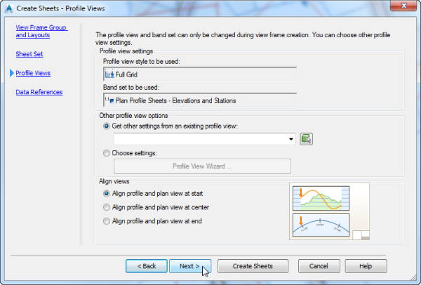
Figure 15.16 Create Sheets – Profile Views page
- Other Profile View Options The Other Profile View Options area lets you modify certain profile view options either by using an existing profile view in your drawing as an example or by running the Profile View Wizard. Regardless of what option you choose, the “other options” you can change are limited to the following in the Profile View Wizard:
- Profile View Datum By Minimum Elevation or Mean Elevation on the Profile View Height page
- Split Profile View options from the Profile View Height page
- All options on the Profile Display Options page
- If available, all options on the Pipe/Pressure Network Display page
- Most of the settings on the Data Bands page
- All options on the Profile Hatch Options page
- All settings on the Multiple Plot Options page
See Chapter 7, “Profiles and Profile Views,” for details on each of these settings. The inactive settings are ones that were previously set when you were going through the settings of the Create View Frames Wizard. If you need to change these settings, you will have to delete your current view frame group and regenerate the view frames with the desired settings.
- Align Views In the Align Views area of the page, you can choose Align Profile And Plan View At Start, Align Profile And Plan View At Center, or Align Profile And Plan View At End.
Create Sheets – Data References Page
The final page of the Create Sheets Wizard (Figure 15.17) is used to create data references in the drawing files that contain your layout sheets.
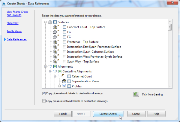
Figure 15.17 Create Sheets – Data References wizard page
- Select The Data You Want Referenced In Your Sheets This area contains a list of objects in the current drawing that can be data referenced into the sheet files. Depending on the way sheet settings were configured in the Create View Frames Wizard (Plan And Profile, Plan Only, or Profile Only), certain objects will be selected for you. If there are other data references you want referenced into the drawing, you may use the check boxes here to select them.

- Pick From Drawing Use the Pick From Drawing button to select those objects you want to data reference from the drawing area.
- Copy Pipe Network Labels To Destination Drawings It's common to create references to pipe networks that are to be shown in plan and/or profile views. If you choose to create references for pipe network objects, you can also copy the labels for those network objects into the sheet file. This saves you from having to relabel your pipe networks.
- Copy Pressure Network Labels To Destination Drawings When this check box is selected, pressure network labels will be copied to the sheet file.
Managing Sheets
After you've completed all pages of the Create Sheets Wizard, you create the sheets by clicking the Create Sheets button. Doing so completes the wizard and starts the creation process. You can also click the Create Sheets button on any pages in this wizard. If you're creating sheets with profile views, you're prompted to select a profile view origin. Civil 3D then displays several dialogs, indicating the process status for the various tasks, such as creating the new sheet drawings and creating the DST file. Once that's complete, the Panorama Event Viewer vista will list two new events, in this example one stating “Sheets created were added to the sheet set file C:\Mastering\Ch15\FinishedSheets\VFG - Frontenac Drive - (1).dstC:\Mastering\Ch15\FinishedSheets
If Sheet Set Manager isn't currently open, it opens with the newly created DST file loaded. The sheets are listed, and the details of the drawing files for each sheet appear (Figure 15.18).
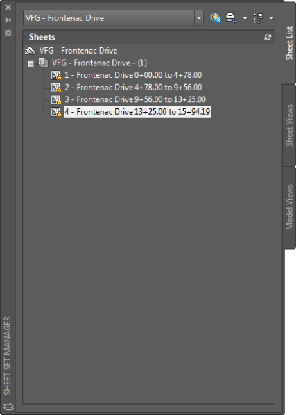
Figure 15.18 New sheets in Sheet Set Manager
If you double-click to open the new drawing file that contains the newly created sheets, you'll see layout sheet tabs created for each of the view frames as selected in the Create Sheets Wizard. The sheets are named using the Name template as defined in the Create Sheets Wizard. Figure 15.19 shows the names that result from the following template:
<[View Frame Group Alignment Name]> <[View Frame Start Station Value]>
to <[View Frame End Station Value]>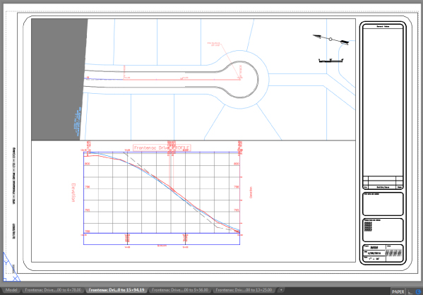
Figure 15.19 The template produces the Frontenac Drive tab names shown here assigned to each sheet
To create the final sheets in this new drawing, Civil 3D creates external references (XRefs) to the drawing containing the view frames; creates direct data references (DRefs) for the alignments, profiles, and any additional objects you selected in the Create Sheets Wizard; and, if profile sheet types were selected in the Create View Frames Wizard, creates profile views in the final sheet drawing.
The following exercise pulls all these concepts together:
- Open the
1503_SheetsWizard.dwg1503_SheetsWizard_METRIC.dwgThis drawing contains the view frame group, alignment, and profile for Frontenac Drive. Note that the drawing doesn't have profile views.
- To launch the Create Sheets Wizard, from the Output tab Plan Production panel, choose Create Sheets.
For some users, the Panorama might appear, stating that the template was not found in the original location. Dismiss the notification.
- On the View Frame Group And Layouts page, do the following:
- Verify that View Frame Range is set to All.
- Verify that Number Of Layouts Per New Drawing is set to 10.
Since this view frame group has fewer than 10 view frames, only one drawing will be generated, but it is good practice to set this value to 10 nonetheless.
- Set Layout Name to <[View Frame Group Alignment Name]> <[View Frame Start Station Value]> to <[View Frame End Station Value]>.
- From the Choose The North Arrow Block To Align In Layouts drop-down list, select North.
- Click Next to advance to the next page.
- On the Sheet Set page, do the following:
- Select the New Sheet Set option and set Name to VFG - Frontenac Drive (or VFG - Frontenac Drive_METRIC for metric users).
- For the Sheet Set File Storage Location option, use the ellipsis to browse to
C:\Mastering\Ch15\FinishedSheetsNotice that by changing this location, the Sheet Files Storage Location entry automatically changes to match.
- Verify that Sheet File Name is set to the following for metric users:
<[View Frame Group Name]> - (<[Next Counter]>) for Imperial users or <[View Frame Group Name]> - (<[Next Counter]>)_METRIC - Click Next to advance to the next page.
- On the Profile Views page, do the following:
- For Other Profile View Options, select Choose Settings and then click the Profile View Wizard button.
The Create Multiple Profile Views dialog opens.
- On the left side of the Create Multiple Profile Views dialog, click Profile Display Options to jump to that page.
- On the Create Multiple Profile Views – Profile Display Options page, verify that the Draw option is selected for only the EG – Frontenac Drive profile and the Frontenac Drive FG profile.
- Scroll to the right and verify that the Labels setting for the EG – Frontenac Drive profile is set to No Labels and that the Frontenac Drive FG Profile is set to Complete Label Set.
- On the left side of the Create Multiple Profile Views dialog, click Data Bands to jump to that page.
- On the Create Multiple Profile Views – Data Bands page, change Profile2 to Frontenac Drive FG for both bands.
- Click Finish to dismiss the Create Multiple Profile Views Wizard and return to the Create Sheets Wizard.
- Verify that Align Views is set to Align Profile And Plan View At Start.
- Click Next to advance to the next page.
- For Other Profile View Options, select Choose Settings and then click the Profile View Wizard button.
- On the Data References page, confirm that at minimum the Frontenac Drive alignment and both the EG – Frontenac Drive and Frontenac Drive FG profiles are selected; then click Create Sheets to complete the wizard.
Before creating the sheets, Civil 3D must save your current drawing.
- Click OK when prompted to save.
The drawing is saved, and you're prompted for an insertion point for the profile view. The location you pick represents the lower-left corner of the profile view grid.
- Select an open area in the drawing, above the right side of the site plan.
Civil 3D displays a progress dialog box, and then the Panorama palette is displayed with information about the results of the sheet-creation process.
- Close the Panorama palette.
After the sheet-creation process is complete, the Sheet Set Manager window opens.
- Click the first sheet of the sheet set shown in Figure 15.20, named Frontenac Drive 0+00.00 to 4+78.00 (or Frontenac Drive 0+000.00 to 0+250.00 for metric users).
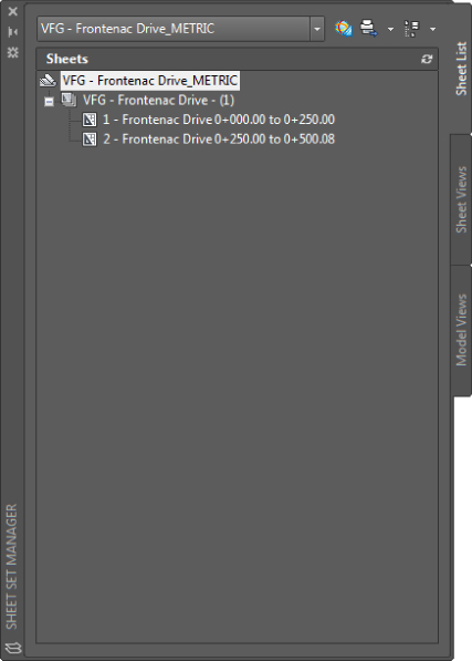
Figure 15.20 Sheet Set Manager once the sheet-creation process is complete
Notice that the name conforms to the Name template and includes the alignment name and the station range for the sheet.
- Review the details listed for the sheet by hovering over the sheet on the Sheet List tab of Sheet Set Manager or by right-clicking in the white space of the dialog and selecting Preview/Details Pane. In particular, note the filename and storage location.
- Double-click this sheet to open the new sheets drawing and display the layout tab for Frontenac Drive 0+00.00 to 4+78.00 (or Frontenac Drive 0+000.00 to 0+250.00 for metric users). Dismiss the Panorama of any warnings.
- Review the multiple tabs created in this drawing file as previously shown in Figure 15.19. If layout tabs are not displayed, then you may turn them on in the Options dialog by going to the Display tab Layout Elements area, filling the Display Layout And Model Tabs check box, and then clicking OK.
The template used also takes advantage of AutoCAD fields, some of which don't currently have values assigned.
When this exercise is complete, you can close the drawing. A saved copy of this drawing is available from the book's web page with the filename 1503_SheetsWizard_FINISHED.dwg1503_SheetsWizard_METRIC_FINISHED.dwgFinishedSheetsAuthor
Now that you have the plan and profile sheets generated, let's look at generating some section sheets using the Plan Production feature.
Creating Section Sheets
Creating section sheets is a two-step process; it's just like creating plan and profile sheets but with one difference: There are no view frames to tweak. Instead, you will have section sheets, which are objects. Section sheets have group plot styles assigned to them that control the arrangement of section arrays per sheet. These section sheets are created when you run the Create Multiple Section Views command using the Production option. If you have already created multiple section views using the Draft option, you will have to re-create your section views using the Production option. This is a prerequisite for running the Create Section Sheets command. Here is the two-step process:
- Generate multiple section views with the Placement option set to Production. You will have the opportunity to select styles to use for section view, section, and group plot styles as you work through the wizard. All section views created with this command become part of a section view group that can be managed from Prospector.
- Generate section sheets, which will create your layouts and your sheet set. Section sheet layouts are created in the same drawing as your production section views; there is no option to create them in new drawings.
Creating Multiple Section Views
Before creating multiple section views for the purpose of sheet creation, be sure you have section, section view, and group plot styles in place. If you have any questions about these styles, refer to Chapter 19.
In this exercise, you'll walk through creating multiple section views for the main road of the sample set:
- Open the
1504_MultipleSectionViews.dwg1504_MultipleSectionViews_METRIC.dwgIn this drawing, sample lines have been added along the Frontenac Drive alignment. These lines are sampling the existing and proposed surfaces.

- From the Home tab Profile & Section Views panel, choose Section Views Create Multiple Views to display the Create Multiple Section Views Wizard, shown in Figure 15.21.
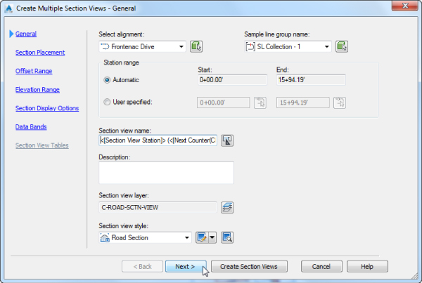
Figure 15.21 Create Multiple Section Views – General wizard page
- On the General page, do the following:
- Verify that Section View Style is set to Road Section.
- Click Next to advance to the next page.
The Section Placement page (Figure 15.22) is where you configure your placement options. If you select Production, you must use the ellipsis to browse to the DWT file containing your section layouts and choose the layout desired based on sheet border and viewport scale. If you select Draft, section views will be laid out in a single grid format.
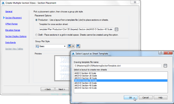
Figure 15.22 Create Multiple Section Views – Section Placement page and Select Layout As Sheet Template dialog
- On the Section Placement page, do the following:
- In the Placement Options area, verify that Production is selected.
- For Template For Cross Section Sheet, use the ellipsis to browse to
C:\Mastering\CH15MasteringSectionTemplate.dwtMasteringSectionTemplate_METRIC.dwt - Verify that Group Plot Style is set to Basic.
- Click Next to advance to the next page.
The Offset Range page (Figure 15.23) determines the width of the section views.
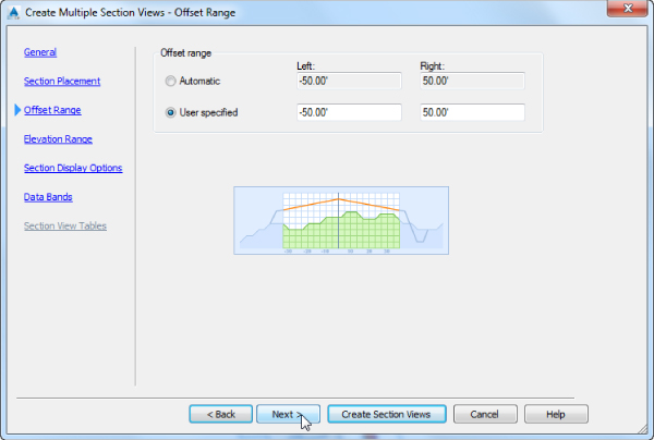
Figure 15.23 Create Multiple Section Views – Offset Range page
- On the Offset Range page, do the following:
- Using the User Specified option, set the left offset range to -50′ (or -20 m for metric users).
- Set the right offset range to 50′ (or 20 m for metric users).
- Click Next to advance to the next page.
The Elevation Range page (Figure 15.24) determines the height of the section views. The options on the Elevation Range page help if you have extra-tall sections, allowing you to set some limits manually.
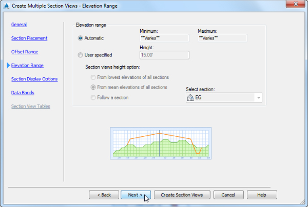
Figure 15.24 Create Multiple Section Views – Elevation Range page
- On the Elevation Range page, click Next to advance to the next page.
- On the Section Display Options page, do the following:
- Verify that the Label Set column for all the items is set to _No Labels. Leave all the other settings as default.
- Verify that in the Style column the style for EG is set to Existing Ground, the style for FG is set to Finished Ground, and each of the corridor surface styles is set to Basic, as shown in Figure 15.25.
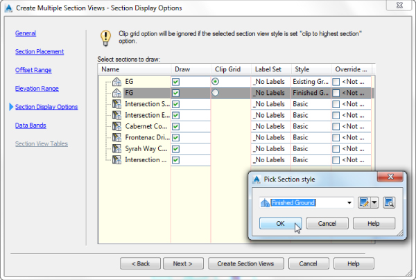
Figure 15.25 Changing styles in the Create Multiple Section Views – Section Display Options wizard page
- Click Next to advance to the next page.
- On the Data Bands page, do the following:
- Verify that the Select Band Set drop-down list is set to Offsets Only.
- Under Set Band Properties, verify that Surface1 is set to EG and Surface2 is set to FG, as shown in Figure 15.26.
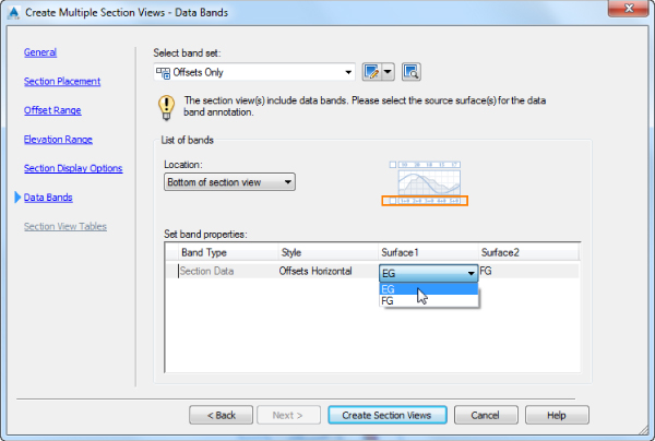
Figure 15.26 Create Multiple Section Views – Data Bands wizard page
- Click Create Section Views to dismiss the wizard and place your section views in the drawing.
- Click a point to the east of the plan view to draw the section views and sheet outlines.
Your drawing should look something like Figure 15.27.
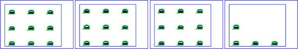
Figure 15.27 The finished multiple section views operation
When this exercise is complete, you can close the drawing. A saved copy of this drawing is available from the book's web page with the filename 1504_MultipleSectionViews_FINISHED.dwg1504_MultipleSectionViews_METRIC_FINISHED.dwg
Now that you have your production section views, you can begin the process of creating section sheets for plotting.
Creating Section Sheets
Many long transportation projects such as highways, light-rail, or canals require the production of many section sheets. In this exercise, you'll convert a section view group into a collection of sheets and place them in a new sheet set.
- Open the
1505_CreatingSectionSheets.dwg1505_CreatingSectionSheets_METRIC.dwgThis file contains the section view group for the Frontenac Drive alignment.

- From the Output tab Plan Production panel, choose Create Section Sheets to display the Create Section Sheets dialog.
- In the Create Section Sheets dialog, do the following:
- Verify that New Sheet Set name is set to FrontenacSections (FrontenacSections_METRIC).
- Click the ellipsis to set Sheet Set Storage Location to
C:\Mastering\Ch15\FinishedSheets
The Create Section Sheets dialog should now look similar to Figure 15.28.
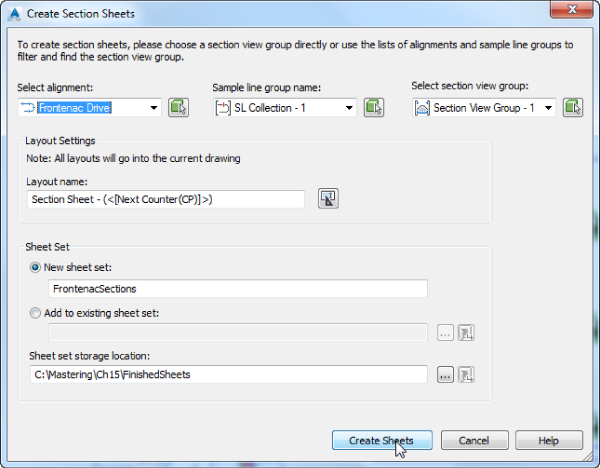
Figure 15.28 The Create Section Sheets dialog
Note that when you are creating section sheets in a drawing where there is more than one section view group, you will have to repeat this command for each section view group.
- Click Create Sheets to dismiss the dialog and generate sheets.
Before creating the sheets, Civil 3D must save your current drawing.
- Click OK when prompted to save.
The drawing is saved, and Civil 3D will generate new layouts in the drawing and sheets in a sheet set. Sheet Set Manager will appear.
- Switch to the Section Sheet – (2) layout tab.
Your layout should look something like Figure 15.29.
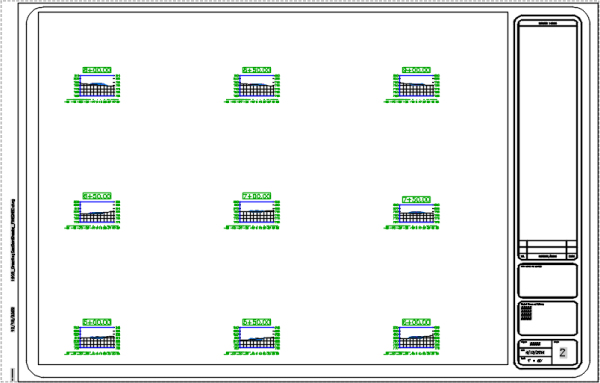
Figure 15.29 A completed section sheet
- Close the Sheet Set Manager palette.
When this exercise is complete, you can close the drawing. A saved copy of this drawing is available from the book's web page with the filename 1505_CreatingSectionSheets_FINISHED.dwg1505_CreatingSectionSheets_METRIC_FINISHED.dwgFinishedSheetsAuthor
While there are still some tweaks to be made to any sheet, large portions of the mundane details are handled by the wizards and tools. There are some elements that you can modify to customize these details for your organization, and you'll look at those in the next section.
Drawing Templates
The beginning of this chapter mentioned that there are several prerequisites to using the Plan Production tools in Civil 3D. The list includes drawing templates (DWT) set up to work with the Plan Production feature and styles for the objects generated by this feature. In this section of the chapter, you'll learn how to prepare drawing templates for use in creating your finished sheets.
Civil 3D ships with several predefined template files for various types of sheets that Plan Production can create. By default, these templates are installed in a subfolder called Plan ProductionTemplateTemplate
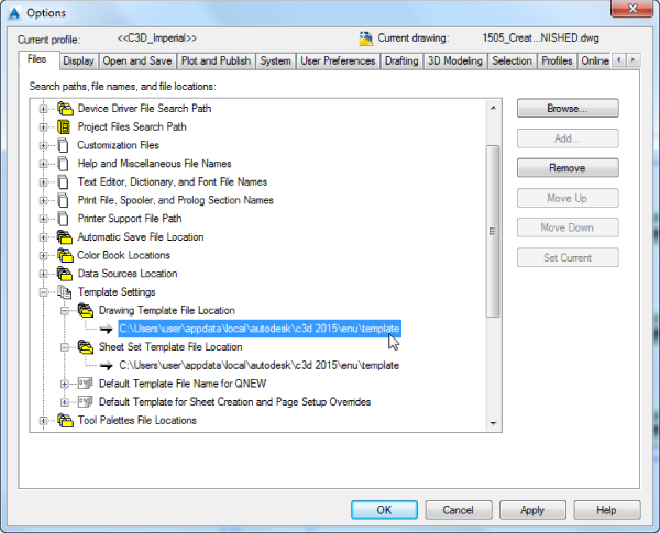
Figure 15.30 Template files location
Figure 15.31 shows the default contents of the PlanProduction
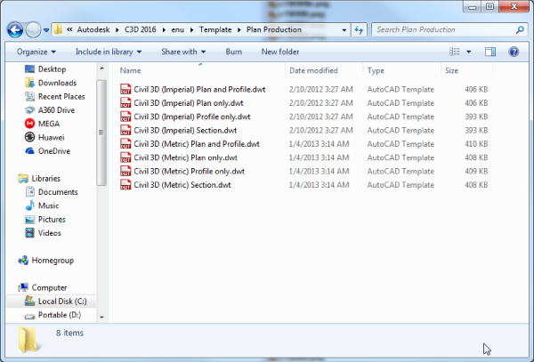
Figure 15.31 Plan Production DWT files
As previously discussed, each template contains layout tabs with pages set to various sheet sizes and plan scales. For example, the Civil 3D (Imperial) Plan and Profile.dwt

Figure 15.32 Various predefined layouts in standard DWT
If you decide to make your own Plan Production templates, it is good practice to provide multiple drawing sizes and scales so that you have them available when you go to make your sheets. But beyond just having them available, make sure that the layout names that you provide in your Plan Production template are descriptive enough that you know which one to select. You may also insert a border on each layout tab or opt to externally reference the border later, after sheets are created.
The viewports in these templates must be rectangular in shape and must have Viewport Type set to Plan, Profile, or Section, depending on the intended use. You set Viewport Type on the Design tab of the Properties dialog, as shown in Figure 15.33.
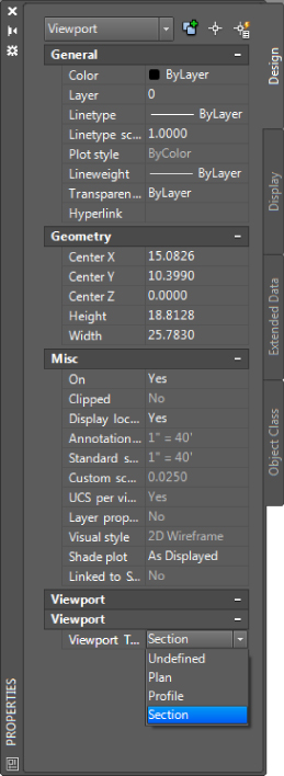
Figure 15.33 Viewport Properties – Viewport Type
The Bottom Line
- Create view frames. When you create view frames, you must select the template file that contains the layout tabs that will be used as the basis for your sheets. This template must contain predefined viewports. You can define these viewports with extra vertices so you can change their shape after the sheets have been created.
- Master It Open the
MasterIt_1501.dwgMasterIt_1501_METRIC.dwgMasteringPandPTemplate.dwtMasteringPandPTemplate_METRIC.dwtC:\Mastering\Ch15\
- Master It Open the
- Edit view frames. The grips available to edit view frames allow the user some freedom on how the frames will appear.
- Master It Continue working in the previous exercise file or open the
MasterIt_1501_FINISHED.dwgMasterIt_1501_METRIC_FINISHED.dwg
- Master It Continue working in the previous exercise file or open the
- Generate sheets and review Sheet Set Manager. You can create sheets in new drawing files or in the current drawing. The resulting sheets are based on the template you chose when you created the view frames. If the template contains customized viewports, you can modify the shape of the viewport to better fit your sheet needs.
- Master It Open the
MasterIt_1503.dwgMasterIt_1503_METRIC.dwgMasteringPandPTemplate.dwtMasteringPandPTemplate_METRIC.dwt
- Master It Open the
- Create section views. More and more municipalities are requiring section views. Whether this is a mile-long road or a meandering stream, Civil 3D can handle it nicely via Plan Production.
- Master It Open the
MasterIt_1504.dwgMasterIt_1504_METRIC.dwgMasteringSectionTemplate.dwtMasteringSectionTemplate_METRIC.dwtC:\Mastering\Ch15\FinishedSheets
- Master It Open the