FIRE DETECTION SYSTEMS
Everyone complains that a robot is good for nothing—except, perhaps, providing its master with a way to tinker with gadgets in the name of “science”! But here’s one useful and potentially life-saving application you can give your robot in short order: fire and smoke
detection. As this chapter will show, you can easily attach sensors to your robot to detect
flames, heat, and smoke, making your robot into a mobile smoke detector.
Flame detection requires little more than a sensor that detects infrared light and a circuit to
trigger a motor, siren, computer, or other device when the sensor is activated. As it turns
out, almost all phototransistors are specifically designed to be sensitive primarily to infrared
or near-infrared light. You need only connect a few components to the phototransistor and
you’ve made a complete flame detection circuit. Interestingly, the detector can “see” flames
that we can’t. Many gases, including hydrogen and propane, burn with little visible flame.
The detector can spot them before you can, or before the flames light something on fire and
smoke fills the room.
The simple circuit in Fig. 34-1 shows the most straightforward method for detecting flames.
(See parts list in Table 34-1.) You mask a phototransistor so it sees only infrared light by
using an opaque infrared filter. Some phototransistors have the filter built in; with others,
you'll have to add the filter yourself. If the phototransistor does not have an infrared-filtered
lens, add one for the light to pass through. Place the transistor at the end of a small opaque
tube, say one with a  - or
- or  -in I.D. (the black tubing for drip irrigation is a good choice).
Glue the filter to the end of the tube. The idea is to block all light to the transistor except
that which is passed through the filter.
-in I.D. (the black tubing for drip irrigation is a good choice).
Glue the filter to the end of the tube. The idea is to block all light to the transistor except
that which is passed through the filter.
- or -in I.D. (the black tubing for drip irrigation is a good choice).
Glue the filter to the end of the tube. The idea is to block all light to the transistor except
that which is passed through the filter.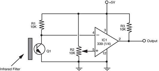
IC1 |
LM339 quad comparator IC |
R1, R3 |
10K resistor |
R2 |
10K potentiometer |
Q1 |
Infrared-sensitive phototransistor |
Misc. |
Infrared filter for phototransistor (if needed) |
If you are looking for an infrared filter, a low-cost one that you can use is a piece of overexposed
film negative. While digital cameras are becoming very popular, there are still a lot
of film cameras being used and you should be able to get a scrap of processed overexposed
film negative from a photo developer.
In the circuit, when infrared light hits the phototransistor it triggers on. The brighter the
infrared source is, the more voltage is applied to the inverting input of the comparator. If
the input voltage exceeds the reference voltage applied to the noninverting input, the output
of the comparator changes state.
Potentiometer R2 sets the sensitivity of the circuit. You’ll want to turn the sensitivity down
so ambient infrared light does not trigger the comparator. You’ll find that the circuit does not
work when the background light has excessive infrared content. You can’t, for example, use
the circuit when the sensor is pointed directly at an incandescent light or the sun.
Test the circuit by connecting an LED and 270-Ω resistor from the Vout terminal to
ground. Point the sensor at a wall, and note the condition of the LED. Now, wave a match
in front of the phototransistor. The LED should blink on and off. You’ll notice that the circuit
is sensitive to all sources of infrared light, which includes the sun, strong photolamps,
and electric burners. If the circuit doesn’t seem to be working quite right, look for hidden
sources of infrared light. With the resistor values shown, the circuit is fairly sensitive; you
can change them by adjusting the value of R1 and R2.
No doubt you’ve watched a fire at the beach or in a fireplace and noted that the flame
changes color depending on the material being burned. Some materials burn yellow or
orange, while others burn green or blue (indeed, this is how those specialty fireplace logs
burn in different colors). Just like the color signature given off when different materials burn,
the flames of the fire flicker at different but predictable rates.
You can use this so-called flame modulation in a robot fire detection system to determine
what is a real fire and what is likely just sunlight streaming through a window or light from a
nearby incandescent lamp. By detecting the rate of flicker from a fire and referencing it
against known values, it is possible to greatly reduce false alarms. The technique is beyond
the scope of this book, but you could design a simple flame-flicker system using an op amp,
a fast analog-to-digital converter, and a computer or microcontroller. The analog-to-digital
converter would translate the instantaneous brightness changes of the fire into digital signals.
The patterns made by those signals could then be referenced against those made by
known sources of fire. The closer the patterns match, the greater the likelihood that there
is a real fire. In a commercial product of this nature, it is more likely that the device would
use more sophisticated digital signal processing.
A pyroelectric sensor is sensitive to the infrared radiation emitted by most fires. The most
common use of pyroelectric infrared (or PIR) sensors is in burglar alarms and motion detectors.
The sensor detects the change in ambient infrared radiation as a person (or animal or
other heat-generating object) moves within the field of view of the sensor. The key ingredient
here is change: a PIR sensor cannot detect heat per se but the changes in the heat
within its field of view. In larger fires, the flickering flames create enough of a change to trigger
the PIR detector.
Chapter 30, “Object Detection,” discusses how to use PIR sensors to detect the motion
of people and animals around a robot. The same sensor, with little or no change, can be
employed to detect fires. To be effective as a firefighter, you should ideally reduce the sensor’s
field of view so the robot can detect smaller fires. The larger the field of view, the more
the temperature and/or position of the heat source must change in order for the PIR sensor
to detect it.
With a smaller field of view, the magnitude of change can be lower. However, with a
small field of view, your robot will likely need to sweep the room, using a servo or stepper
motor, in order to observe any possible fires. The sweeping must stop periodically so the
robot can take a room reading. Otherwise, the motion of the sensor could trigger false
alarms.
“Where there’s smoke, there’s fire.” Statistics show that the majority of fire deaths each
year are caused not by burns but by smoke inhalation. For less than $15, you can add
smoke detection to your robot’s long list of capabilities and with a little bit of programming
have it wander through the house checking each room for trouble. You’ll probably want to
keep it in the most fire-prone rooms, such as the basement, kitchen, laundry room, and
robot lab.
You can build your own smoke detector using individually purchased components, but
some items, such as the smoke detector cell, are hard to find. It’s much easier to use a commercially
available smoke detector and modify it for use with your robot. In fact, the process
is so simple that you can add one to each of your robots. Tear the smoke detector apart and
strip it down to the base circuit board.
The active element used for detecting smoke—the radioactive substance Americium
241—has a half-life of approximately seven years. After about five to seven years, the
effectiveness of the alarm is diminished, and you should replace it. Using a very old alarm
will render your “Smokey the Robot” fairly ineffectual at detecting the smoke of fires.
Remember to properly dispose of old smoke detectors according to the rules and laws
where you live.
You can either buy a new smoke detector module for your robot or scavenge one from a
commercial smoke alarm unit. The latter tends to be considerably cheaper—you can buy
quality smoke alarms for as little as $7 to $10. Hacking a commercial smoke alarm, specifically
a Kidde model 0915K, so it can be directly connected to a robot’s computer port or
microcontroller will be presented in this chapter. Of course, smoke alarms are not all
designed the same, but the basic construction is similar to that described here. You should
have relatively little trouble hacking most any smoke detector.
However, you should limit your hacking attempts to those smoke alarms that use traditional
9-V batteries. Certain smoke alarm models, particularly older ones, require AC power
or specialized batteries (such as 22-V mercury cells). These are harder to salvage and, besides,
their age makes them less suitable for sensitive smoke detection.
Start by checking the alarm for proper operation. If it doesn’t have one already, insert
a fresh battery into the battery compartment. Put plugs in your ears (or cover up the audio
transducer hole on the alarm). Press the test button on the alarm; if it is properly functioning
the alarm should emit a loud, piercing tone. If everything checks out okay, remove
the battery, and disassemble the alarm. Less expensive models will not have screws but
will likely use a snap-on construction. Use a small flat-headed screwdriver to unsnap the
snaps.
Inside the smoke detector will be a circuit board, like the one in Fig. 34-2, that consists
of the drive electronics and the smoke detector chamber.
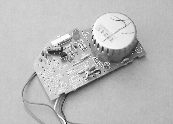
Either mounted on the board or located elsewhere will be the piezo disc used to make
the loud tone. Remove the circuit board, being careful you don’t damage it. Examine the
board for obvious hack points, and note the wiring to the piezo disc. More than likely, there
will be either two or three wires going to the disc.
- Two wires to the piezo disc. The wires will provide ground and +V power. This design is typical when you are using all-in-one piezo disc buzzers, in which the disc itself contains the electronics to produce the signal for audible tones.
- Three wires to the piezo disc. The wires will provide ground, +V power, and a signal that causes the disc to oscillate with an audible tone.
Using a volt-ohm meter, find the wire that serves as ground. It is probably black or
brown, but if no obvious color coding is used, examine the circuit board and determine
where the wires are attached. An easy way to find the ground connection is to find the
lowest resistance wire to the negative battery lead. Connect the other test lead to the
remaining wire, or if the disc has three wires, connect the test lead to one of the remaining
wires.
Replace the battery in the battery compartment, and depress the test button on the
alarm. Watch for a change in voltage. For a two-wire disc you should see the voltage change
as the tone is produced. For a three-wire disc, try each wire to determine which produces
the higher voltage; that is the one you wish to use.
Once you have determined the functions of the wires to the piezo disc, clip off the disc
and save it for some other project. Retest the alarm’s circuit board to make sure you can still
read the voltage changes with your volt-ohm meter. Then clip off the wires to the battery
compartment, noting their polarity. Connect the circuit to a +5 V power supply. Depress the
test button again. Ideally, the circuit will still function with the lower voltage. If it does not,
you’ll need to operate the smoke alarm circuit board with +9 V, which can complicate your
robot’s power supply and interfacing needs.
Remember to note the voltage when the piezo disc is active. It should not be more than
+5 V; if it is, that means the circuit board contains circuitry for increasing the drive voltage
to the piezo disc. You don’t want this when you are interfacing the board to a computer port
or microcontroller, so you’ll need to limit the voltage by using a circuit such as that shown
in Fig. 34-3. Here, the output of the smoke alarm circuit is clamped at no more than 5.1 V,
thanks to the 5.1-V zener diode.
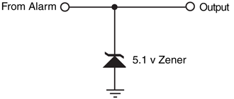
Figure 34-3 Use a 5.1 V zener diode to ensure
that the smoke alarm output does not drive the computer/microcontroller input above 5 V.
There is no effective way to measure the peak voltage by using a volt-ohm meter, because
the output of the smoke alarm detector is often an oscillating signal. The meter will only
show an average of the voltage provided by the circuit. If you are limited to using only a volt-ohm
meter for your testing, for safety’s sake add the 5.1-V zener circuit as shown in Fig. 34-3. While this may be unnecessary in some instances, it will help protect your digital
interface from possible damage caused by overvoltage from the smoke alarm circuit board.
Assuming that the board works with +5 V applied, your hacking is basically over, and you
can proceed to interface the alarm with a computer port or microcontroller. By way of
example, we’ll assume that a simple microcontroller that periodically polls the input pin is
connected to the smoke alarm circuit board. The program checks the pin several times each
second. When the pin goes HIGH, the smoke alarm has been triggered.
If your microcontroller supports interrupts (ideally with latched inputs that can be
polled), a better scheme is to connect the smoke alarm circuit board to an interrupt pin. Then write your software so that if the interrupt pin input state changes, a special “I smell
smoke” routine is run. The benefit of an interrupt or latched input over polling is that the
latter requires your program to constantly branch off to check the condition of the input
pin. With an interrupt or latched input, your software program can effectively be ignorant
of any smoke detector functionality. If and when the signal pin is active because the smoke
alarm circuit was tripped, a special software routine takes over, commanding the robot to
do something else.
Rather than connect the output of the smoke alarm circuit board directly to the input
pin, use a buffer to protect the microcontroller or computer against possible damage. You
can construct a buffer using logic circuits (either TTL or CMOS) or with an op amp wired
for unity-gain (with unity-gain, the op amp doesn’t amplify anything). Note also that the
smoke alarm circuit board derives its power from the robot’s main +5 V power supply and
not from the microcontroller.
Alternatively, you can use an opto-isolator. The opto-isolator bridges the gap between
the detector and the robot. You do not need to condition the output of the opto-isolator if
you are connecting it to a computer or microprocessor port or to a microcontroller.
Once the smoke alarm circuit board is connected to the microcontroller or computer port,
test it and your software by triggering the test button on the smoke alarm. The software
should branch off to its “I smell smoke” subroutine. For a final test, light a match, and then
blow it out. Wave the smoldering match near the smoke detector chamber. Again, the software
runs the “I smell smoke” subroutine.
You should be aware of certain limitations inherent in robot fire detectors. In the early
stages of a fire, smoke tends to cling to the ceilings. That’s why manufacturers recommend
that you place smoke detectors on the ceiling rather than on the wall. Only when the fire
gets going and smoke builds up does it start to fill up the rest of the room.
Your robot is probably a rather short creature, and it might not detect smoke that confines
itself only to the ceiling. This is not to say that the smoke detector mounted on even a
1-ft-high robot won’t detect the smoke from a small fire; just don’t count on it. Back up the
robot smoke sensor with conventionally mounted smoke detection units, and do not rely
only on the robot’s smoke alarm.
Smoke alarms detect the smoke from fires but not noxious fumes. Some fires emit very little
smoke but plenty of toxic fumes, and these are left undetected by the traditional smoke
alarm. Moreover, potentially deadly fumes can be produced in the absence of a fire. For
example, a malfunctioning gas heater can generate poisonous carbon monoxide gas. This
colorless, odorless gas can cause dizziness, headaches, sleepiness, and—if the concentration
is high enough—even death.
Just as there are alarms for detecting smoke, so there are alarms for detecting noxious
gases, including carbon monoxide. Such gas alarms tend to be a little more expensive than
smoke alarms, but they can be hacked in much the same way as a smoke alarm. Deduce
the signal wires to the piezo disc and connect them (perhaps via a buffer and zener diode
voltage clamp) to a computer port or microcontroller.
Combination units that include both a smoke and gas alarm are also available. You should
determine if the all-in-one design will be useful for you. In some combination smoke–gas
alarm units, there is no simple way to determine which has been detected. Ideally, you’ll want
your robot to determine the nature of the alarm, either smoke or gas (or perhaps both).
In a fire, smoke and flames are most often encountered before heat, which isn’t felt until the
fire is going strong. But what about before the fire gets started in the first place, such as
when a kerosene heater is inadvertently left on or an iron has been tipped over and is melting
the nylon clothes underneath?
If your robot is on wheels (or legs) and is wandering through the house, perhaps it’ll be
in the right place at the right time and sense these irregular situations. A fire is brewing, and
before the house fills with smoke or flames the air gets a little warm. Equipped with a heat
sensor, the robot can actually seek out warmer air, and if the air temperature gets too high
it can sound an initial alarm.
Realistically, heat sensors provide the least protection against a fire. But heat sensors are
easy to build, and, besides, when the robot isn’t sniffing out fires it can be wandering through
the house giving it an energy check or reporting on the outside temperature or . . . you get
the idea.
Fig. 34-4shows a basic but workable circuit centered around an LM355 temperature
sensor (it and the other parts in the circuit are listed in Table 34-2). This device is relatively
easy to find and costs under $1.50. The output of the device, when wired as shown, is a linear
voltage. The voltage increases 10 mV for every rise in temperature of 1° Kelvin (K).
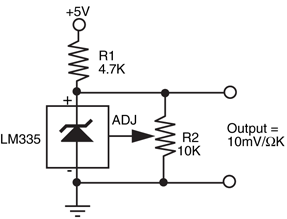
R1 |
4.7K resistor, 1 percent tolerance |
R2 |
10K 10-turn precision potentiometer |
D1 |
LM335 temperature sensor diode |
Degrees Kelvin uses the same scale as degrees Celsius (C), except that the zero point is
absolute zero—about -273C. One degree Centigrade equals 1° Kelvin; only the start points
differ. You can use this to your advantage because it lets you easily convert degrees Kelvin
into degrees Celsius. Actually, since your robot will be deciding when hot is hot, and doesn’t
care what temperature scale is used, conversion really isn’t necessary.
You can test the circuit by connecting a volt-ohm meter to the ground and output terminals
of the circuit. At room temperature, the output should be about 2.98 V. You can calculate
the temperature if you get another reading by subtracting the voltage by 273 (ignore
the decimal point but make sure there are two digits to the right of it, even if they are zeros).
What’s left is the temperature in degrees Celsius. For example, if the reading is 3.10 V, the
temperature is 62C (310 - 273 = 62). By the way, that’s pretty hot (144° Fahrenheit).
You can calibrate the circuit, if needed, by using an accurate bulb thermometer as a reference
and adjusting R2 for the proper voltage. By knowing the temperature, you can
determine what the output voltage should be by adding the temperature (in degrees Celsius)
to 273. If the temperature is 20C, then the output voltage should be 2.93 V. For more
accuracy, float some ice in a glass of water for 15 to 20 minutes and stick the sensor in it
(keep the leads of the testing apparatus dry). Wait 5 to 10 minutes for the sensor to settle
and read the voltage. It should be exactly 2.73 V.
The load presented at the outputs of the sensor circuit can throw off the reading. The
schematic in Fig. 34-5 and parts list in Table 34-3 provides a buffer circuit so the load does
not interfere with the output of the 355 temperature sensor. Note the use of the decoupling
capacitors as recommended in the manufacturer’s application notes. These aren’t
essential, but they are a good idea.

Figure 34-5 An enhanced wiring scheme for the
LM355 temperature sensor. The load of the output is
buffered and does not affect the reading from the LM355.
R1 |
12K resistor, 1 percent tolerance |
C1, C3 |
0.1 μ ceramic capacitor |
C2, C4 |
4.7 μ tantalum capacitor |
D1 |
LM335 temperature sensor diode |
By attaching a small fire extinguisher to your robot, you can have the automaton put out
the fires it detects. Obviously, you’ll want to make sure that the fire detection scheme you’ve
put into use is relatively free of false alarms and that it doesn’t overreact to normal situations.
Having your robot rush over to one of your guests and put out a cigarette he just lit
is a potential values judgment.
It’s a good idea to use a clean fire-extinguishing agent for your firefighting ’bot. Halon is
one of the best such agents, but is no longer manufactured for general consumption. Alternatives
include inert gases (helium, argon) and noncombustible gases (e.g., nitrogen), and
they will not leave a sediment on whatever they are sprayed on.
No matter what you use for the fire extinguisher, be sure to use caution as a guide when
building any firefighting robot. Consider limiting your robot for experimental use, and test
it only in well-ventilated rooms—or better yet, outside.
The exact mounting and triggering scheme you use depends entirely on the design of the
fire extinguisher. The bottle used in the prototype firebot is a Kidde Force-9, 2 lb Halon
extinguisher. It has a diameter of about 3 in. You can mount the extinguisher in the robot
by using plumber's tape, that flexible metallic strip used by plumbers to mount water and
gas pipes. It has lots of holes already drilled into it for easy mounting. Use two strips to hold
the bottle securely. Remember that a fully charged extinguisher is heavy—in this case over
3 lb (2 lb for the Halon chemical and about lb for the bottle). If you add a fire extinguisher
to your robot, you must relocate other components to evenly distribute the weight.
lb Halon
extinguisher. It has a diameter of about 3 in. You can mount the extinguisher in the robot
by using plumber's tape, that flexible metallic strip used by plumbers to mount water and
gas pipes. It has lots of holes already drilled into it for easy mounting. Use two strips to hold
the bottle securely. Remember that a fully charged extinguisher is heavy—in this case over
3 lb (2 lb for the Halon chemical and about lb for the bottle). If you add a fire extinguisher
to your robot, you must relocate other components to evenly distribute the weight.The extinguisher used in the prototype system for this book used a standard actuating
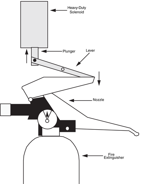
valve. To release the fire retardant, you squeeze two levers together. Fig. 34-6 shows how to
use a heavy-duty solenoid to remotely actuate the valve. You may be able to access the valve
plunger itself (you may have to remove the levers to do so). Rig up a heavy-duty solenoid
and lever system. A computer or control circuit activates the solenoid.
For best results, the valve should be opened and closed in quick bursts (200 to 300 ms
are about right). The body of the robot should also pivot back and forth so the extinguishing
agent is spread evenly over the fire. Remember that to be effective, the extinguishing
agent must be sprayed at the base of the fire, not at the flames. For most fires, this is not a
problem because the typical robot stays close to the floor. If the fire is up high, the robot
may not be able to effectively fight it.
You can test the fire extinguisher a few times before the bottle will need recharging. The
fully charged bottle in the prototype was able to squeeze off several dozen short blasts
before the built-in pressure gauge registered that a new charge was needed. Don’t use your
only extinguisher for your robot experiments; keep an extra handy in the unlikely event that
you have to fight a fire yourself.
If the firefighting robot bug bites you hard, consider entering your machine in the annual
Trinity College Firefighting Home Robot Contest (see www.trincoll.edu/events/robot/ for
additional information, including rules and a description of the event). This contest involves
timing a robot as it goes from room to room in a houselike test field (the “house” and all its
rooms are in a reduced scale). The object is to find the fire of a candle and snuff it out in the
least amount of time. Separate competitions involving a junior division (high school and
younger) and a senior division (everyone else) help to provide an even playing field for the
contestants.
Rather than a fire extinguisher, competition firefighting ’bots usually use a fan (such as
the muffin fans used to cool computer systems) to blow out the candle that is used as the
fire source. The advantages of the fan over the fire extinguisher is its light weight, fairly low
power consumption, and ease in which it can be scanned about to blow out the flame.
To learn more about . . . |
Read |
|
Connecting sensors to computers and microcontrollers |
Chapter 14,“Computer Peripherals” |
|
Adding the sensation of “touch” |
Chapter 29, “The Sense of Touch” |
|
Optical systems for detecting light |
Chapter 32, “Robot Vision” |
|
Enabling the robot to move around in a room or house |
Chapter 33, “Navigating through Space” |
|
Adding a siren or other warning device |
Chapter 31, “Sound Output and Input” |