Chapter 3
Structures, Airfoils, and Aerodynamic Forces
AIRCRAFT STRUCTURES
Up to this point you may have considered only the wing an important structure of an aircraft within the concept of aerodynamics. But in fact the entire structure of the airplane plays a role in the efficiency of an aircraft in flight, and identifying how, and to what extent, each part of an airplane structure plays a role is an important first step. A review of the more prominent structures discussed in aerodynamics is covered here first, because their direct role on lift and drag provide the foundation for more complicated discussions in the future.
Flight control systems are commonly separated into two areas, primary and secondary systems. Primary control systems include the ailerons, elevator (stabilator), and rudder and, depending on the aircraft type and aircraft speed, give the pilot a “feel” of how the aircraft is performing. Secondary systems such as trim systems, flaps, spoilers, and leading edge devices are used in relieving control pressures for the pilots, assisting primary control surfaces in high‐speed flight, or improving the performance characteristics of the aircraft in general.
Aircraft are flown in various configurations of gear and flaps, but for this textbook we will commonly refer to clean and dirty as the two reference configurations. In a clean configuration, the gear is retracted (when applicable), and the flaps and other high‐lift devices are retracted. In the dirty configuration, the gear is considered down and locked, and the high‐lift devices are fully deployed.
Figure 3.1 contains a sample of the airfoils found on modern aircraft, and many that we will discuss throughout the subsequent chapters.
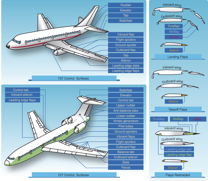
Figure 3.1 Modern transport category control surfaces.
U.S. Department of Transportation Federal Aviation Administration, Pilot's Handbook of Aeronautical Knowledge, 2008
Primary Flight Controls
Ailerons
The ailerons are usually located on the trailing edge of each wing closer to the outboard area by the tip. Ailerons control roll about the longitudinal axis as they move opposite of each other when the pilot banks left or right with the yoke or stick, with the “up” aileron on the downward moving wing. Most ailerons are connected by a mechanical means to the aircraft yoke through cables, bell cranks, pulleys, and/or push‐pull tubes. Some jet aircraft have additional ailerons located in the midwing area for high‐speed maneuvering, to reduce roll rate.
There are many styles of ailerons used throughout the fixed‐wing aircraft industry today, including differential ailerons, Frise‐type ailerons, and flaperons. Differential ailerons work by deflecting the up aileron more than the down aileron, increasing drag on the downward wing counteracting adverse yaw (Fig. 3.2). Frise‐type ailerons project the leading edge of the raised aileron into the wind, increasing drag on the lowered wing to once again minimize the effects of adverse yaw (Fig. 3.3). Flaperons combine the control surfaces of the ailerons with the function of the trailing edge flaps, as they can be lowered like flaps but still control bank angle like traditional ailerons. Chapter 15 will discuss these items, as well as adverse yaw, in more depth regarding aircraft stability.
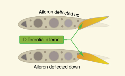
Figure 3.2 Differential ailerons.
U.S. Department of Transportation Federal Aviation Administration, Pilot's Handbook of Aeronautical Knowledge, 2008
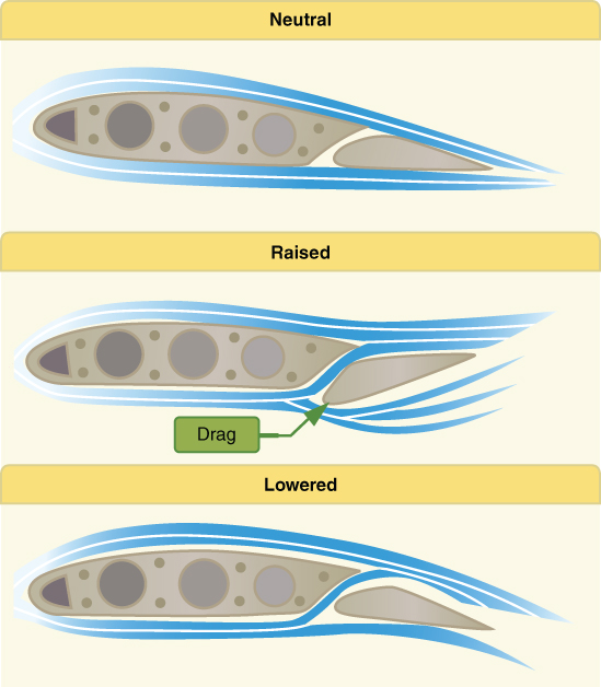
Figure 3.3 Frise‐type ailerons.
U.S. Department of Transportation Federal Aviation Administration, Pilot's Handbook of Aeronautical Knowledge, 2008
Elevator/Stabilator
An elevator or stabilator controls pitch about the lateral axis, allowing for varying angles of attack during flight. An elevator is attached to the trailing edge of the horizontal stabilizer, which is usually fixed to the empennage, sometimes with an angle of incidence built in. A stabilator is a one‐piece horizontal stabilizer where the whole unit moves around a pivot point in order to allow the pilot to once again control the angle of attack by adjusting the tail down force resulting in pitch variations of the nose of the aircraft.
The elevator is controlled by the pilot through various mechanical linkages, when the pilot pulls aft on the stick the elevator goes up and when the pilot pushes forward the elevator goes down. As we discussed in Chapter 2, the tail down force provides a moment that moves the nose of the aircraft around the aircraft's center of gravity. In the example of an up elevator, when the pilot pulls aft on the stick, a larger “camber” is created on the tail and thus a greater aerodynamic force is created (Fig. 3.4).
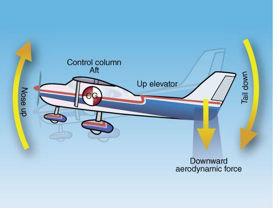
Figure 3.4 Elevator movement.
U.S. Department of Transportation Federal Aviation Administration, Pilot's Handbook of Aeronautical Knowledge, 2008
A stabilator essentially works like the elevator, but due to the fact the entire rear horizontal piece is movable, more force is created when the pilot moves the stick fore and aft and sensitivity is increased. This leads to greater chances of the pilot overcontrolling the aircraft so components like an antiservo tab and balance weight are added to reduce the sensitivity.
Some larger aircraft incorporate an adjustable horizontal stabilizer controlled by a jackscrew through a wheel in the cockpit or a motor. Though an elevator is still located on the trailing edge, the usually fixed horizontal stabilizer is adjustable, in this case allowing the pilot to move the stabilizer to reduce control pressures on the stick (Fig. 3.5).
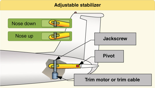
Figure 3.5 Adjustable horizontal stabilizer.
U.S. Department of Transportation Federal Aviation Administration, Pilot's Handbook of Aeronautical Knowledge, 2008
Rudder
The rudder controls yaw, or movement of the aircraft about its vertical axis. Similar to the smaller, movable elevator attached to the trailing edge of the horizontal stabilizer, the rudder is attached to the rear of the fixed vertical stabilizer. As with other components we discussed, the rudder is connected to the rudder pedals in the cockpit via various mechanical linkages; pressing on the left or right rudder pedal moves the rudder left or right respectfully. Most of the time the rudder is used to maintain coordinated flight, especially when banking the aircraft. As will be discussed later in this chapter, moving the rudder creates a larger camber on the vertical stabilizer, which in turn creates a greater sideways force. This force then moves the nose of the aircraft left and right, or yaw, around the vertical axis (Fig. 3.6).
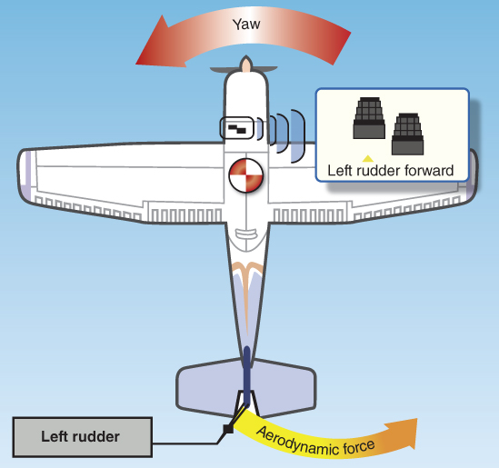
Figure 3.6 Rudder movement.
U.S. Department of Transportation Federal Aviation Administration, Pilot's Handbook of Aeronautical Knowledge, 2008
Secondary Flight Controls
Secondary flight control systems usually consist of wing flaps, leading edge devices, spoilers, and trim systems. These controls often support or supplement the primary controls, and their importance to understanding aerodynamic principles cannot be overstated.
Flaps
The flaps are the most common high‐lift devices used on aircraft, and their contribution to the amount of lift an airfoil can produce will be discussed in more detail in Chapter 4. For our discussion here we will review their location on the aircraft, as well as the basic flap designs on aircraft today.
Some flaps are located on the trailing edge of the wing, usually inboard close to the fuselage, and are referred to as trailing edge flaps. These surfaces contribute to the camber of the wing airfoil in most cases, as well as to the area of the wing in other cases. By increasing the angle of attack of the wing, and in some cases the area of the wing, they allow the aircraft to fly at lower speeds, which may be needed for takeoff and landing or for times of increased maneuverability. For this discussion we will look at four types of flaps: plain, split, slotted, and fowler; and as you can see there are designs where the benefit of one design is combined with another (Fig. 3.7).
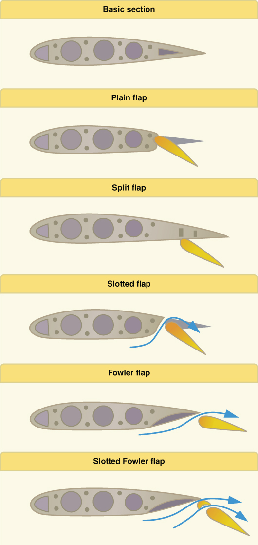
Figure 3.7 Common flap designs.
U.S. Department of Transportation Federal Aviation Administration, Pilot's Handbook of Aeronautical Knowledge, 2008
The plain flap is the simplest design and usually used to describe the advantages and purpose of flaps. As the flaps are deployed, the camber of the wing increases and the  (discussed in Chapter 4) increases accordingly with the angle of attack. The farther the flaps are deployed, the greater the lift and the resulting drag. A split flap is deployed from underneath the wing, and results in more drag initially than the plain flap due to the disruption of the flow of air around the bottom and top of the wing.
When the flaps are slotted, at high angles of attack high energy air is allowed to move through the slot and energize the air on top of the deployed flap. This allows for an increase in  at lower speeds, allowing an aircraft to operate out of shorter landing strips or with obstacles surrounding the airport. The highly energized air also delays boundary layer separation, which lowers the stalling speed, improving performance at slow speeds. More on this topic will be discussed throughout this textbook.
Fowler flaps are commonly found on larger transport category aircraft, as they are heavier than the other flap designs and incorporate more complex systems to operate. Fowler flaps slide out and back from the wing, which offers the benefit of not only increasing the camber of the wing but also of the wing area. Fowler flaps also double as slotted flaps in that they allow higher‐energy air from beneath the wing to flow over the deployed flap area. Cessna high‐wing, single‐engine aircraft are the best example of the use of Fowler flaps on light aircraft.
Leading Edge Devices
Leading edge devices are discussed in more depth in Chapter 4 so only a brief review will be presented here. As with trailing edge flaps, leading edge devices like movable slots, leading edge flaps (Krueger flaps), and leading edge cuffs work to increase the  over a wing, allowing the aircraft to fly at slower speeds for takeoff and landing. In some cases the camber of the wing is also increased, which allows for an increase in the angle of attack and increased performance. As with trailing edge flaps, the first setting results in more lift with little increase in drag, while fully deployed settings usually result in mostly drag with little lift.
Spoilers
Spoilers are used on many different types of aircraft as high‐drag devices used to increase drag and reduce lift. They “spoil” the smooth air around a wing, and may be used in flight, or on the ground when landing or during a rejected takeoff. Some aircraft use the spoilers in flight for roll control at higher airspeeds when the action of the ailerons would be too much of a force. Sometimes spoilers are used as speed brakes to reduce lift on both wings, which allows the aircraft to descend without increasing airspeed.
Trim Systems
Trim systems are designed to alleviate the pressures on the primary flight controls as experienced by the pilot during aircraft operation. Usually located on the trailing edge of these devices, the pilot (or autopilot) operates the respective trim system in order to position the flight control where minimum pressures are exerted in the system. The two most common trim systems are trim tabs and antiservo tabs.
A trim tab is usually found on the trailing edge of the elevator or rudder, and unlike the antiservo tab, the trim tab moves in the opposite direction to which the primary control moves (Fig. 3.8). An antiservo tab is found on the trailing edge of a stabilator, and moves in the same direction as the primary control to which it is attached (Fig. 3.9). As previously mentioned, the antiservo tab serves to reduce the sensitivity of the stabilator during pitch to the pilot, as well as reducing control pressure as needed.
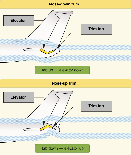
Figure 3.8 Trim tabs.
U.S. Department of Transportation Federal Aviation Administration, Pilot's Handbook of Aeronautical Knowledge, 2008
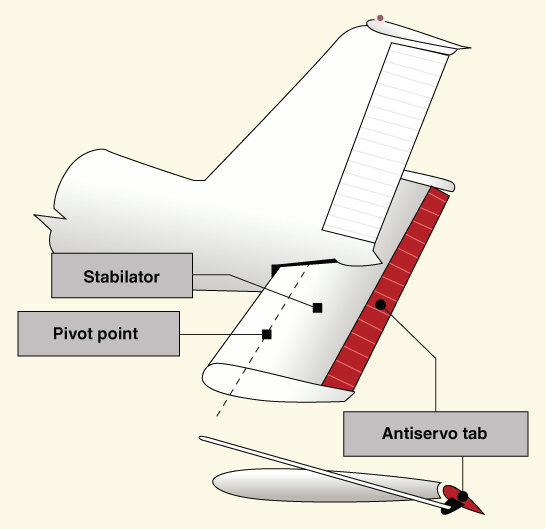
Figure 3.9 Antiservo tab.
U.S. Department of Transportation Federal Aviation Administration, Pilot's Handbook of Aeronautical Knowledge, 2008
AIRFOILS
An airfoil or, more properly, an airfoil section, is commonly shown as a vertical slice of a wing (see Fig. 3.10). In discussing airfoils in this chapter, the planform (or horizontal plane) of the wing is ignored as it will be discussed later. Keep in mind during this discussion that an airfoil is also found on the vertical stabilizer, horizontal stabilizer, and rotor blades. Wingtip effects, sweepback, taper, wash/out or wash/in, and other design features are not considered. No singular airfoil design is perfect for every flight situation, wind tunnel tests, and computer‐generated designs dictate what airfoil is best for the mission of the aircraft.
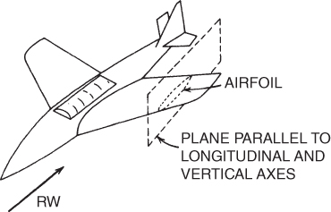
Figure 3.10 Airfoil section.
Airfoil Terminology
The terminology used to discuss an airfoil is shown in Fig. 3.11:
- Chord line is a straight line connecting the leading edge and the trailing edge of the airfoil.
- Chord is the length of the chord line. All airfoil dimensions are measured in terms of the chord.
- Mean camber line is a line drawn equidistant between the upper surface and the lower surfaces.
- Maximum camber is the maximum distance between the mean camber line and the chord line. The location of maximum camber is important in determining the aerodynamic characteristics of the airfoil.
- Maximum thickness is the maximum distance between the upper and lower surfaces, and its location of maximum thickness will also be important when determining aerodynamic characteristics.
- Leading edge radius is a measure of the sharpness of the leading edge. It may vary from zero for a knife‐edge supersonic airfoil to about 2% (of the chord) for rather blunt leading‐edge airfoils.
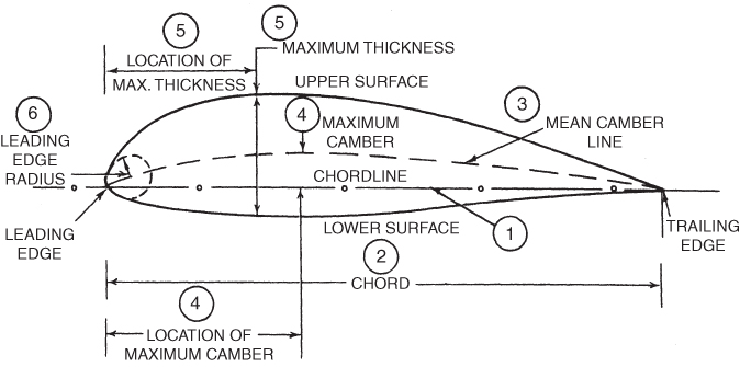
Figure 3.11 Airfoil terminology.
Definitions
- Flight Path Velocity The speed and direction of a body passing through the air.
- Relative Wind (RW) The speed and direction of the air impinging on a body passing through it. It is equal and opposite in direction to the flight path velocity.
- Angle of Attack (AOA or
 , pronounced alpha) The acute angle between the relative wind and the chord line of an airfoil.
 - Aerodynamic Force (AF) The net resulting static pressure multiplied by the planform area of an airfoil.
- Lift The component
 of the aerodynamic force that is perpendicular to the relative wind.
 - Drag The component
 of the aerodynamic force that is parallel to the relative wind.
 - Center of Pressure (CP) The point on the chord line where the aerodynamic force acts.
- Laminar Flow or Streamlined Flow Smooth airflow with little transfer of momentum between parallel layers.
- Turbulent Flow Airflow where the streamlines break up and there is much mixing of the layers.
Geometry Variables of Airfoils
There are four main variables in the geometry of an airfoil:
- Shape of the mean camber line
- Thickness
- Location of maximum thickness
- Leading‐edge radius
If the mean camber line coincides with the chord line, the airfoil is said to be symmetrical. In symmetrical airfoils, the upper and lower surfaces have the same shape and are equidistant from the chord line. Figure 3.12 shows examples of early airfoil design to more modern, supersonic designs.
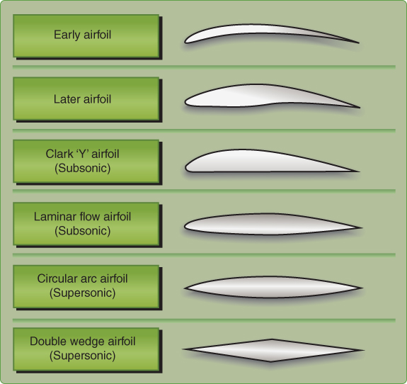
Figure 3.12 Examples of airfoil design.
U.S. Department of Transportation Federal Aviation Administration, Pilot's Handbook of Aeronautical Knowledge, 2008
Classification of Airfoils
Most airfoil development in the United States was done by the National Advisory Committee for Aeronautics (NACA) starting in 1929. NACA was the forerunner of the National Aeronautics and Space Administration (NASA). The first series of airfoils investigated was the “four‐digit” series. The first digit gives the amount of camber, in percentage of chord. The second digit gives the position of maximum camber, in tenths of chord, and the last two give the maximum thickness, in percentage of chord. For example, a NACA 2415 airfoil has a maximum camber of 2% C, located at 40% C (measured from the leading edge), and has a maximum thickness of 15% C. A NACA 0012 airfoil is a symmetrical airfoil (has zero camber) and has a thickness of 12% C.
Further development led to the “five‐digit” series, the “1‐series,” and, with the advent of higher speeds, to the so‐called laminar flow airfoils. The NACA's 23000 series created in 1935 were very popular and are still in use today. The laminar flow airfoils are the “6‐series” and “7‐series” airfoils and result from moving the maximum thickness back and reducing the leading‐edge radius.
Two things happen with this treatment. First, the point of minimum pressure is moved backward, thus increasing the distance from the leading edge that laminar (smooth) airflow exists, which reduces drag. Second, the critical Mach number is increased, thus allowing the airspeed of the aircraft to be increased without encountering compressibility problems. In the 6‐series, the first digit indicates the series and the second gives the location of minimum pressure in tenths of chord. The third digit represents the design lift coefficient in tenths, and the last two digits (as in all NACA airfoils) show the thickness in percentage of chord. For example, NACA 64‐212 is a 6‐series airfoil with minimum pressure at 40% C, a design lift coefficient of 0.2, and a thickness of 12% C. Sketches of NACA subsonic airfoil series are shown in Fig. 3.13.
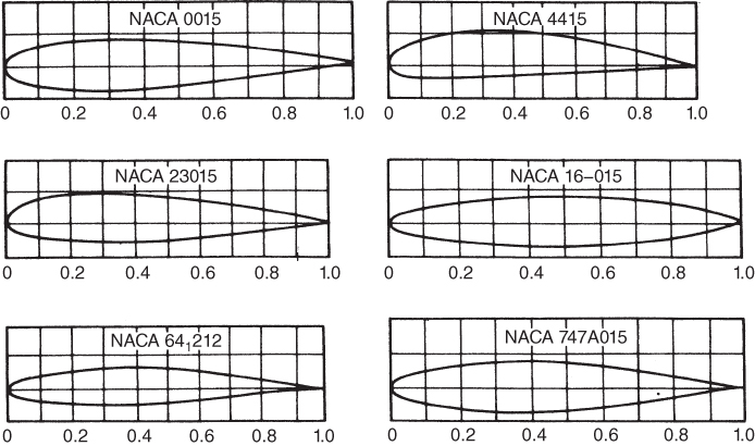
Figure 3.13 NACA airfoils (NACA data).
A modern design used worldwide on corporate, military, and air transport aircraft is the supercritical airfoil, which is flatter on top and more rounded on the bottom than a conventional wing. The upper trailing edge has a downward curve to restore lift lost by the flattening of the upper surface. The benefit of this design in the high‐speed realm of flight, as well as other supersonic airfoils, are discussed in Chapter 16.
DEVELOPMENT OF FORCES ON AIRFOILS
Leonardo da Vinci stated the cardinal principle of wind tunnel testing nearly 400 years before the Wright brothers achieved powered flight. Near the beginning of the sixteenth century, da Vinci said: the action of the medium upon a body is the same whether the body moves in a quiescent medium, or whether the particles of the medium impinge with the same velocity upon the quiescent body. This principle allows us to consider only relative motion of the airfoil and the air surrounding it. We may use such terms as “airfoil passing through the air” and “air passing over the airfoil” interchangeably.
Pressure Disturbances on Airfoils
If an airfoil is subjected to a moving airflow, velocity and pressure changes take place that create pressure disturbances in the airflow surrounding it. These disturbances originate at the airfoil surface and propagate in all directions at the speed of sound. If the flight path velocity is subsonic, the pressure disturbances that are moving ahead of the airfoil affect the airflow approaching the airfoil (Fig. 3.14).
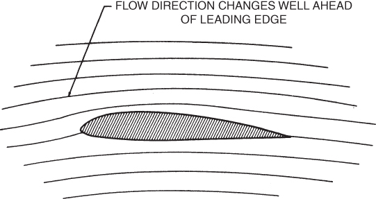
Figure 3.14 Effect of pressure disturbances on airflow around an airfoil.
Velocity and Static Pressure Changes about an Airfoil
The air approaching the leading edge of an airfoil is first slowed down and then speeds up again as it passes over or beneath the airfoil. Figure 3.15 compares two local velocities with the flight path velocity  and with each other. As the velocity changes, so does the dynamic pressure “q” and, according to Bernoulli's principle, so does the static pressure “P.” Air near the stagnation point has slowed down, so the static pressure in this region is higher than the ambient static pressure. Air that is passing above and below the airfoil, and thus has speeded up to a value higher than the flight path velocity, will produce static pressures that are lower than ambient static pressure. So as “q” increases, “P” static pressure decreases and a greater pressure differential is realized.
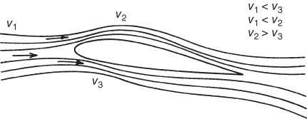
Figure 3.15 Velocity changes around an airfoil.
At a point near maximum thickness, maximum velocity and minimum static pressure will occur. Because air has viscosity, some of its energy will be lost to friction and a “wake” of low‐velocity, turbulent air exists near the trailing edge, resulting in a small, high‐pressure area. Figure 3.16 shows a symmetrical airfoil (a) at zero AOA and the resulting pressure distribution (b) at a positive AOA and its pressure distribution. Arrows pointing away from the airfoil indicate static pressures that are below ambient static pressure; arrows pointing toward the airfoil indicate pressures higher than ambient.
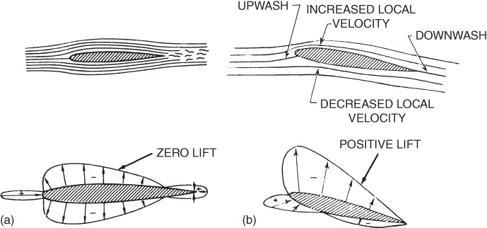
Figure 3.16 Static pressure on an airfoil (a) at zero AOA, and (b) at a positive AOA.
AERODYNAMIC FORCE
Aerodynamic force (AF) is the resultant of all static pressures acting on an airfoil in an airflow multiplied by the planform area that is affected by the pressure. The line of action of the AF passes through the chord line at a point called the center of pressure (CP). It is convenient to consider that the forces acting on an aircraft, or on an airfoil, do so in some rectangular coordinate system. One such system could be defined by the longitudinal and vertical axes of an aircraft. Another could be defined by axes parallel to and perpendicular to the earth's surface. A third rectangular coordinate system is defined by the relative wind direction and an axis perpendicular to it. This last system is chosen to define lift and drag forces. Aerodynamic force (AF) is resolved into two components: one parallel to the relative wind, called drag ( ), and the other perpendicular to the relative wind, called lift (
 ). Figure 3.17 shows the resolution of AF into its components
  and
and  .
.
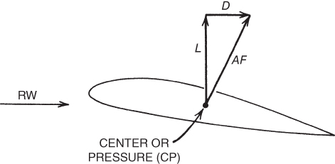
Figure 3.17 Components of aerodynamic force.
Pressure Distribution on a Rotating Cylinder
A stationary (nonrotating) cylinder is located in a wind tunnel as shown in Fig. 3.18a. The cylinder is equipped with static pressure taps. These measure the local static pressure with respect to the ambient static pressure in the test chamber. When the tunnel is started, the airflow approaches the cylinder from the left as shown by the relative wind vector. Arrows pointing toward the cylinder show pressures that are higher (+) than ambient static pressure; arrows pointing away from the cylinder show pressures that are less (−) than ambient static pressure. Figure 3.18a shows that the upward forces are resisted by the downward forces and no net vertical force (lift) is developed by the cylinder.
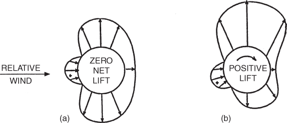
Figure 3.18 Pressure forces on (a) nonrotating cylinder and (b) rotating cylinder.
Now consider if the wind tunnel is stopped, and the cylinder begins to rotate in a motionless fluid. We begin to see the factors of viscosity and friction at work. The more viscous the fluid, the more it is resistant to flow, and since air has viscosity properties it will resist flow. Similar to a wing, the surface of the cylinder has some “roughness” to it, so as the cylinder turns some molecules adhere to the surface. The closer to the surface of the cylinder (airfoil), the greater the possibility the molecules are drawn in a clockwise direction by viscosity, so now substituting air we see the velocity increase in the direction of rotation above the cylinder. This circular movement of the air is called circulation.
Finally let us consider a rotating cylinder in a moving fluid as the cylinder continues rotating in the clockwise direction when the wind tunnel is once again started (Fig. 3.18b). The air passing over the top of the cylinder will be speeded up by circulation, while the air passing over the bottom of the cylinder will be retarded. According to Bernoulli's equation, the static pressure on the top will be reduced and the static pressure on the bottom will be increased, similar to an airfoil with a positive angle of attack. The new pressure distribution will be as shown in Fig. 3.18b, where a low‐pressure area produces an upward force. This is called the Magnus effect, named after Gustav Magnus, who discovered it in 1852. It explains why you slice (or hook) your golf ball or why a good pitcher can throw a curve.
AERODYNAMIC PITCHING MOMENTS
Consider the pressure distribution about a symmetrical airfoil at zero angle of attack (AOA) (Fig. 3.19a). The large arrows show the sum of the low pressures on the top and bottom of the airfoil. They are at the center of pressure (CP) of their respective surfaces. The CP on the top of the airfoil and the CP on the bottom are located at the same point on the chord line. The large arrows indicate that the entire pressure on the top and bottom surfaces is acting at the CP. Because these two forces are equal and opposite in direction, no net lift is generated. Note also that the lines of action of these forces coincide, so there is no unbalance of moments about any point on the airfoil. Figure 3.19b shows the pressure distribution about a symmetrical airfoil at a positive angle of attack (AOA). There is now an unbalance in the upper surface and lower surface lift vectors, and positive lift is being developed. However, the two lift vectors still have the same line of action, passing through the CP. There can be no moment developed about the CP. We can conclude that symmetrical airfoils do not generate pitching moments at any AOA. It is also true that the CP does not move with a change in AOA for a symmetric airfoil.
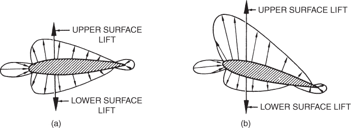
Figure 3.19 Pitching moments on a symmetrical airfoil (a) at zero AOA and (b) at positive AOA.
Now consider a cambered airfoil operating at an AOA where it is developing no net lift (Fig. 3.20a). Upper‐surface lift and lower‐surface lift are numerically equal, but their lines of action do not coincide. A nose‐down pitching moment develops from this situation. When the cambered airfoil develops positive lift (Fig. 3.20b), the nose‐down pitching moment still exists. By reversing the camber it is possible to create an airfoil that has a nose‐up pitching moment. Delta‐wing aircraft have a reversed camber trailing edge to control the pitching moments.
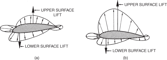
Figure 3.20 Pitching moments on a cambered airfoil: (a) zero lift, (b) developing lift.
AERODYNAMIC CENTER
For cambered airfoils the CP moves along the chord line when the AOA changes. As the AOA increases, the CP moves forward and vice versa. This movement makes calculations involving stability and stress analysis very difficult. There is a point on a cambered airfoil where the pitching moment is a constant with changing AOA, if the velocity is constant. This point is called the aerodynamic center (AC).
The AC, unlike the CP, does not move with changes in AOA. If we consider the lift and drag forces as acting at the AC, the calculations will be greatly simplified. The location of the AC varies slightly, depending on airfoil shape. Subsonically, it is between 23 and 27% of the chord back from the leading edge. Supersonically, the AC shifts to the 50% chord.
In summary, the pitching moment at the AC does not change when the angle of attack changes (at constant velocity) and all changes in lift effectively occur at the AC. As an airfoil experiences greater velocity its AC commonly moves towards the trailing edge, with the AC near 25% chord subsonically and at 50% supersonically.
SYMBOLS
| AC | Aerodynamic center |
| AF | Aerodynamic force (lb) |
| AOA | Angle of attack (degrees) |
| CP | Center of pressure |
 |
Drag (lb) |
 |
Lift (lb) |
| RW | Relative wind |
 (alpha) (alpha) |
Angle of attack (degrees) |
PROBLEMS
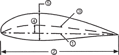
- Number 3 on the drawing shows
- the chord line.
- the maximum camber.
- the thickness.
- the mean camber line.
- Number 4 on the drawing shows
- the chord line.
- the thickness.
- the maximum camber.
- the mean camber line.
- Number 5 on the drawing shows
- the maximum camber.
- the mean camber line.
- the upper‐surface curvature.
- the maximum thickness.
- The Magnus effect explains why
- a bowling ball curves.
- a pitched baseball curves.
- a golf ball slices.
- Both (b) and (c)
- Which of the following will develop positive lift?
- A symmetrical airfoil at zero AOA
- A nonrotating cylinder in a wind tunnel
- A cambered airfoil at zero AOA
- Which of the following will not produce a pitching moment?
- A symmetrical airfoil at a positive AOA
- A cambered airfoil that is developing zero lift
- A cambered airfoil that is at a positive AOA
- A symmetrical airfoil at zero AOA
- Both (a) and (d)
- The aerodynamic center (AC) is located at
- 50% C subsonically and 25% C supersonically.
- 25% C at all speeds.
- 50% C at all speeds.
- 25% C subsonically and 50% C supersonically.
- For a cambered airfoil, the center of pressure (CP)
- moves to the rear of the wing at low AOA.
- moves backward as AOA increases.
- moves forward as AOA increases.
- Both (a) and (c)
- Which of these statements is false? For a cambered airfoil,
- the AC is where all changes in lift effectively take place.
- there is no pitching moment at the AC.
- the AC is located near 25% C subsonically.
- the pitching moment at the AC is constant with change of AOA (at constant airspeed).
- For a symmetrical airfoil,
- the center of pressure moves forward as AOA increases.
- the center of pressure stays at the same place as AOA increases.
- there is no pitching moment about the CP.
- Both (b) and (c)