Chapter 16
High‐Speed Flight
In this chapter we discuss the airflow as the aircraft approaches the speed of sound (high subsonic), transonic flight, and supersonic flight. Hypersonic flight is not discussed.
In subsonic flight, the density change in the airflow is so small that it can be neglected in the flow equations without appreciable error. The airflow at these lower speeds can be compared to the flow of water and is called incompressible flow. At high speeds, however, density changes take place in the airstream that are significant. Thus, this type of airflow is called compressible flow. Transonic, supersonic, and hypersonic flight all involve compressible flow.
Flight speeds have been arbitrarily named as follows:
- Subsonic Aircraft speeds where the airflow around the aircraft is completely below the speed of sound (about Mach 0.7 or less)
- Transonic Aircraft speeds where the airflow around the aircraft is partially subsonic and partially supersonic (from about Mach 0.7 to Mach 1.3)
- Supersonic Aircraft speeds where the airflow around the aircraft is completely above the speed of sound but below hypersonic airspeed (from about Mach 1.3 to Mach 5.0)
- Hypersonic Aircraft speeds above Mach 5.0
THE SPEED OF SOUND
The speed of sound is an important factor in the study of high‐speed flight. Small pressure disturbances are caused by all parts of an aircraft as it moves through the air. These disturbances move outward from their source through the air at the speed of sound. A two‐dimensional analogy is that of the ripples on a pond that result when a stone is thrown in the water.
The speed of sound in air is a function of temperature alone:

where
| a | = | speed of sound |
| a0 | = | speed of sound at sea level, standard day (661 kts) |
| θ | = | temperature ratio, T/T0 |
Since Eq. 16.1 shows that the speed of sound is only a function of temperature, we can see that the higher in altitude an aircraft travels, the lower the speed of sound. Because the aircraft's speed in relation to the speed of sound is so important in high‐speed flight, airspeeds are usually measured as Mach number (named after the Austrian physicist Ernst Mach). Mach number is the aircraft's true airspeed divided by the speed of sound (in the same atmospheric conditions):

where
| M | = | Mach number |
| V | = | true airspeed (knots) |
| a | = | speed of sound (knots) |
When an aircraft is flying below the speed of sound, the pressure disturbances will be moving faster than the airplane (think ripples on a pond again), and those disturbances that travel ahead of the aircraft influence or “warn” the approaching airflow. This “pressure warning” can be observed in a smoke wind tunnel as it causes the upwash well ahead of the wing. This is shown in Fig. 16.1a.
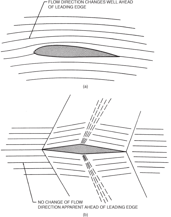
Figure 16.1 (a) Subsonic flow, (b) supersonic flow.
If the aircraft is flying at a speed greater than the speed of sound, the airflow ahead of the aircraft is not influenced by the pressure field of the aircraft, since the speed of the pressure disturbances is less than the speed of the aircraft. The airflow ahead of the wing will have no warning of the approach of the wing and will not change its direction ahead of the wing's leading edge. Since the pressure waves are no longer “parting the way” for the oncoming wing, the particles pile up in front of the wing and thus suddenly undergo extreme changes in pressure, density, and temperature. This is shown in Fig. 16.1b. Two new “V‐speeds” can now be introduced when dealing with the maximum operating speeds of jet aircraft:
- VMO – Maximum operating speed: Maximum operating speed in knots.
- MMO – Maximum operating speed (Mach): Maximum operating speed in terms of Mach (speed of sound).
Coffin Corner
New pilots to the world of high‐speed flight are introduced to the term “coffin corner” a situation in flight at high speed and high altitude where the stall speed of the aircraft in Mach number equals the MMO of the aircraft. If the pilots slow the aircraft they will stall the aircraft; if they speed up they will exceed the maximum operating speed. This is due to the change in density and temperature as an aircraft climbs in altitude. Remember that the Mach number is the ratio of TAS to the speed of sound at the current flight conditions for the aircraft. As the aircraft climbs in altitude, the KTAS increases. In order to achieve the same dynamic pressure across the wing at higher altitudes, the KTAS must increase, though the KCAS read by the pilot may remain the same. Also remember that as we increase our altitude the speed of sound decreases, so as KTAS increases and the speed of sound decreases, the Mach ratio increases. If an aircraft is climbed at a constant Mach close to MMO, eventually it will reach a point where it will not be able to speed up due to MMO, or slow down due to the fact the KCAS is at stall speed because KCAS was decreasing during the climb.
HIGH‐SUBSONIC FLIGHT
Compressibility effects are not limited to aircraft that fly supersonically. A high‐subsonic velocity will produce local supersonic flow on top of the wings, fuselage, and other parts of the aircraft that greatly impact performance characteristics. Helicopters often experience compressibility effects on rotor tips; this can occur even when the helicopter is in a hover. The most important compressibility effect that occurs in subsonic aircraft is the formation of normal shock waves on the aircraft's wings or rotor blades. Once this occurs the aircraft will be subject to an increase in drag, and possible other negative forces the pilot may not have anticipated include buffeting and aircraft control difficulties.
Normal Shock Wave Formation on Wings
Airflow increases in velocity as it passes over a wing surface, so the local Mach number on top of the wing is always greater than the flight Mach number. For example, if an aircraft is flying at  , the local velocity might be
  at the thickest point of the wing (depending on the thickness and or camber of the airfoil). This is shown in Fig. 16.2.
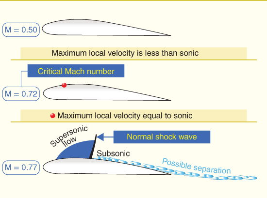
Figure 16.2 Airflow over a wing section.
U.S. Department of Transportation Federal Aviation Administration, Pilot's Handbook of Aeronautical Knowledge, 2008
If the flight Mach number increases, the local velocity on top of the wing also increases. At some flight Mach number the local maximum velocity reaches sonic speed,  . This flight Mach number is called the critical Mach number, Mcrit. For the example shown in Fig. 16.2, Mcrit is 0.72.
Once Mcrit is exceeded, the aircraft is flying in the transonic speed range and a new set of drag and aerodynamic forces can be expected. Most jet aircraft will cruise just below their critical Mach number to avoid the negative effects of transgressing into the transonic range. Supersonic airflow exists in the area of maximum thickness on top of the wing, but subsonic flow exists elsewhere. All pressure disturbances behind this sonic flow cannot be propagated forward because they run into sonic velocities traveling rearward. A normal shock wave is formed as shown in Fig. 16.2. This shock wave is present where the air slows from supersonic to subsonic. As the air flows through the normal shock wave it undergoes a rapid compression. The compression decreases the kinetic energy of the airstream and converts it into a pressure and temperature increase behind the shock wave. The heat rise behind the shock wave is either radiated to the atmosphere or absorbed by the wing surface, but in either case it is lost. The lost energy must be continuously supplied by the engines. This creates a type of drag known as wave drag.
The increase in static pressure caused by the normal shock wave has the same effect as the adverse pressure gradient that was discussed in basic aerodynamics. It slows the air in the boundary layer down to the point where faster‐moving air from outside the boundary layer rushes in and reverse flow occurs. This process is at the “possible separation” area in Fig. 16.2.
DESIGN FEATURES FOR HIGH‐SUBSONIC FLIGHT
Subsonic jet aircraft can increase airspeed without encountering shock wave problems if the critical Mach number can be raised, so understanding when this occurs and designing airfoils to delay the onset of Mcrit are of great importance. Several design features help accomplish this:
- Thin airfoil sections
- Airfoil sections that have good high‐subsonic Mach number characteristics
- Sweepback
- Vortex generators
Thin Airfoil Sections
The thinner the airfoil, the less the air is speeded up in passing over the top surface; thus, the airspeed can be higher before the air reaches Mcrit. One disadvantage of thin wings is that they do not have high values of CL(max), so higher takeoff and landing speeds are required. Another disadvantage is that it is difficult to design the structural strength and rigidity required in a thin wing. Many aircraft that fly close to, or exceed, the speed of sound also incorporate various high‐speed flight controls that may be located on the wing, and thus must be incorporated into the structure of the wing along with the necessary hydraulic control or fly‐by‐wire controls. Finally, there is less room for fuel tanks in a thin wing as compared to a thicker wing of the same planform.
High‐Speed Subsonic Airfoils
The laminar flow airfoil discussed in Chapter 5 was the first high‐speed airfoil. Moving the maximum thickness backward from about 25% C to 40–50% C did reduce drag and increase the critical Mach number, but one disadvantage still existed for this type of airfoil. The shock wave that develops on a laminar airfoil occurs in the adverse pressure gradient region. As the airflow is slowing up in this region it has a tendency to separate (stall) easily.
The supercritical airfoil shown in Fig. 16.3 was designed in the 1970s by NASA to correct this deficiency and lower fuel costs. It currently is in use on corporate jets, military aircraft, and transport category aircraft around the world. Flatter on the top and rounded on the bottom, it is shaped so that the normal shock will occur where the upper surface pressure gradient is favorable or zero. At that point the boundary layer is able to encounter the pressure increase across the shock wave without separating. The surface curvature on the top surface of the supercritical airfoil is less than a conventional laminar airfoil, so the local Mach number will be less than that for the laminar flow airfoil. If Mcrit is exceeded, the airflow will be supersonic nearer the leading edge on the supercritical airfoil. However, the airflow will remain at a much lower Mach number, and the supersonic flow will be terminated by a gradual deceleration. Therefore, no shock wave will result and drag will be less. Though some lift is lost due to less curvature of the top of the wing, the trailing edge is more curved than a conventional wing and a portion of the lift is restored. The gain in reduction of drag and increase in fuel efficiency result in a much improved design compared with previous wing designs.
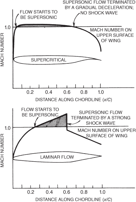
Figure 16.3 Comparison of supercritical and laminar flow airfoils at Mach 0.75.
Sweepback
One of the most common methods of delaying the effects of compressibility and increasing the critical Mach number is to sweep the wings backward (and more recently, to sweep them forward). Other negative effects of exceeding the critical Mach speed, like force divergence Mach number and Mach tuck, are also delayed, which allows the aircraft to travel faster before onset. Instead of presenting the complicated conventional discussion of this, a simpler explanation is presented here.
Unlike a straight‐wing, the leading edge of the swept wing does not strike the oncoming air at 90°, so the full effect of compressibility is not felt until the swept‐wing aircraft is flying at a higher speed compared to the same speed of a straight‐wing aircraft. We learned earlier that thin wings will increase the Mcrit. By sweeping the wings the effective chord (parallel to the aircraft's longitudinal axis) has been lengthened, but the wing thickness has not been changed. Thus, the ratio of thickness/chord has been reduced. In effect, the wing thickness has been reduced and a higher Mcrit results.
The coefficient of lift curve is affected by sweep in two ways. First, the value of CL(max) is reduced, so takeoff and landing speeds are increased. Second, the curve flattens and has no sharp stall AOA point. Figure 16.4 shows these.
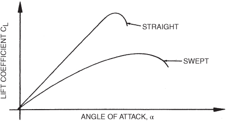
Figure 16.4 Effect of wing sweep on a  curve.
The lack of a definite stall point has caused some complacency in pilots who are making a transition from straight‐wing to swept‐wing aircraft. While it is true that the swept‐wing aircraft does not show a clean stall, it is also true that sweeping the wings decreases the aspect ratio, and this means a large increase in induced drag coefficient. This is particularly dangerous during takeoffs and landings, as was emphasized earlier. Wing sweep is also important in directional and lateral stability as discussed in Chapter 15. Wingtip stall is increased by swept‐back wings, as was presented in Chapter 12; the greater the wing sweep and wing taper, the greater the influence of wingtip stalls. Sweeping the wings forward will eliminate this problem.
Vortex Generators
Use of vortex generators to invigorate the boundary layer and thus delay separation in the low‐speed region of flight was discussed in Chapter 4. The same general principles apply to the high‐speed region of flight. Shock‐induced separation occurs because the boundary layer does not have enough energy to overcome the adverse pressure gradient through a shock wave. Vortex generators mix higher kinetic energy air from outside the boundary layer with the slower air in the boundary layer and delay separation.
If a normal shock wave does develop, vortex generators are effective in breaking it up. The additional drag of the generators is small in comparison to the wave drag that they help dissipate. Figure 16.5 shows the action of vortex generators.
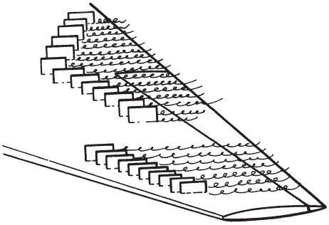
Figure 16.5 Vortex generators.
TRANSONIC FLIGHT
Early attempts to “break the sound barrier” were not very successful because of problems encountered in the transonic region. When these problems were better understood, several important design changes were made, and today supersonic aircraft have little difficulty in flying through this speed region. Subsonic aircraft do not have these design changes and will experience difficulties if the critical Mach number is exceeded, hence the importance of delaying the onset of Mcrit. This discussion also applies to subsonic aircraft and helicopters, if they venture into the transonic region of flight, as well as to supersonic aircraft.
Force Divergence
At airspeeds of about 5% above Mcrit the normal shock wave on the top of the wing causes the boundary layer to separate from the wing. This causes a change in the aerodynamic force coefficients, both CL and CD, as well as pitching moments. This airspeed is called the force divergence Mach number.
Figure 16.6 shows the CD curve (for a constant value of CL) plotted against Mach number. When the force divergence Mach number is reached, the value of CD rapidly increases. This velocity is also known as the drag divergence or drag rise Mach number. The drag increase is caused by the energy loss across the normal shock wave and the boundary layer separation and is called wave drag. Note that even though the value of CD again decreases above Mach 1, the total drag continues to increase with airspeed. The rate of increase will be less, however, above Mach 1.
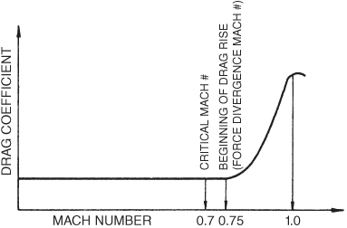
Figure 16.6 Force divergence effect on CD.
In addition to the drag increase behind the normal shock wave, the airflow separation also results in a loss of lift. Figure 16.7 shows a sudden lowering of the coefficient of lift at the force divergence Mach number. Shock‐induced separation creates a local stall situation similar to the low‐speed stall, except that it occurs behind the normal shock wave rather than at the trailing edge of the wing. This causes the center of pressure to be shifted forward and produces a nose‐up pitching moment. If one wing develops a normal shock before the other, a rolling moment can be produced toward the wing with the earlier shock. If a wing drops, the aircraft will tend to yaw in that direction, and a condition similar to Dutch roll may develop. Sweepback reduces the effects of exceeding the force divergence Mach number by lowering the magnitude of the changes in CL, CD, and pitching moments allowing the pilot more control.
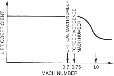
Figure 16.7 Force divergence effect on CL.
Some of the effects of reaching force divergence Mach number are
- An increase in CD for a given value of CL
- A decrease in CL for a given AOA
- A change in pitching moment as the aerodynamic center shifts
Mach Tuck
Once a shock wave forms on the wing, and separation of the boundary layer occurs, pitching moments change on an aircraft and the nose of the aircraft will drop. This is referred to as Mach tuck or tuckunder. Depending on the position of the horizontal stabilizer (or stabilator), “elevator” authority may not be sufficient to compensate for the nose drop without significant input from the pilot. When the flight Mach number is increased beyond the force divergence Mach number, the normal shock wave on top of the wing increases in intensity and moves backward. A second normal shock wave then appears on the bottom of the wing. This is shown in Fig. 16.8. A second factor influencing Mach tuck is the movement of the shock waves toward the rear of the wing. As the top shock moves rearward the separation point also moves rearward and so does the center of pressure, thus adding to the Mach tuck tendency. A third factor is that the aerodynamic center moves from the quarter chord point to the 50% chord point when the aircraft reaches supersonic flight, again influencing the pitching moment of the aircraft.
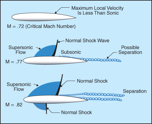
Figure 16.8 Normal shock wave on bottom of wing.
U.S. Department of Transportation Federal Aviation Administration, Airplane Flying Handbook, 2004
All aircraft flying supersonically suffer a nose‐down pitching moment. The shift of the aerodynamic center is not a smooth movement. Sharp leading edges make the shift smoother, but in many aircraft the aerodynamic center moves forward before the eventual rearward shift. This is shown in Fig. 16.9. This movement can cause a pitch‐up moment in the early stages of transonic flight, but eventually it will cause Mach tuck as the speed increases. Figure 16.10 shows the amount of stick forces for a typical jet aircraft as Mach number increases. As the critical Mach number is approached lift increases and stick push is required to maintain level flight as the nose rises. As the shock wave forms above Mach .70 in this example, the nose begins to “tuck” and aft stick (pull) forces are required to compensate.
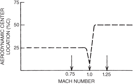
Figure 16.9 Aerodynamic center location shift.
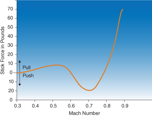
Figure 16.10 Stick forces versus Mach number.
U.S. Department of Transportation Federal Aviation Administration, Airplane Flying Handbook, 2004
Buffet
The violently turbulent separated air behind a normal shock wave often produces buffeting of the aircraft; this can occur as a high‐speed buffet or low‐speed buffet. This is caused by the airflow hitting the horizontal stabilizers, especially when the horizontal stabilizer in located lower on the tail within the wake of the separation from the wing. The T‐tail configuration helps eliminate this problem by putting the horizontal tail above the wing wake, though as we saw in earlier chapters this T‐tail design can have a negative affect during stall recovery. At heavier weights, higher altitude, and with higher “G” loading buffeting can occur due to the increased AOA and boundary layer separation striking the tail.
Flight in the transonic range is undesirable, so supersonic aircraft fly through this region as rapidly as possible.
Control Surface Buzz
Boundary layer separation acting on control surfaces often causes rapid oscillations called buzz or flutter. This can cause metal fatigue problems to hinge fittings and other parts of the control surfaces, and in extreme cases decrease the integrity of the control surfaces inducing failure.
Control Effectiveness
Shock‐induced separation can reduce the effectiveness of control surfaces in two ways. First, if the surface is located in a region of stalled air, it is operating in an “aerodynamically dead” air mass and cannot produce effective aerodynamic forces. Second, control surfaces are effective if they change the airflow around the entire wing or stabilizer. When there is a shock wave ahead of the control surface, deflection of that surface cannot influence the airflow ahead of the shock wave, so what little aerodynamic force is developed is restricted to the control surface and area behind the shock wave.
SUPERSONIC FLIGHT
As the flight Mach number increases in the transonic speed range, the upper and lower normal shock waves increase in size and strength and move to the trailing edge of the wing, as shown in Fig. 16.11.
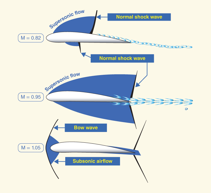
Figure 16.11 Normal shock waves move to trailing edge.
U.S. Department of Transportation Federal Aviation Administration, Pilot's Handbook of Aeronautical Knowledge, 2008
When the flight Mach number is 1.0, the entire airfoil is supersonic, except the leading‐edge stagnation area. The shock waves at the trailing edge are still normal shock waves, so the velocity behind them is still subsonic. A new shock wave now appears ahead of the airfoil. It is a compression wave just like the normal shock wave, and because the air at the leading edge is subsonic, the new wave, called a bow wave, must also be a normal shock wave, at least in the area directly ahead of the leading edge. The air ahead of the shock wave is greater than the speed of sound, and the air between the shock wave and leading edge is subsonic due to stagnation, so a normal shock wave exists.
Figure 16.12 shows a bow wave ahead of the leading edge. Fully supersonic flight exists when the bow wave becomes attached to the leading edge of the wings, nose of the aircraft, tail sections, and all other parts of the aircraft.
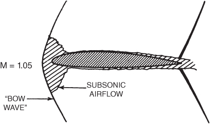
Figure 16.12 Unattached bow wave at transonic speed.
The bow wave may not attach easily if the leading edges are too blunt. Sharp leading edges are used on supersonic aircraft, but it still is necessary for the flight Mach number to be greater than 1.0 for all the airflow to be supersonic. Thus, the supersonic range starts at about Mach 1.2 to 1.3, depending on individual aircraft design. The normal waves at the trailing edges also are deflected backward and now are called oblique shock waves.
Oblique Shock Waves
An oblique shock wave, like a normal shock wave, is a compression wave. It differs from the normal shock because the airflow direction changes as air flows through it and the airflow slows down but remains supersonic. To see how an oblique shock wave forms, consider a wedge‐shaped object placed in a supersonic flow, as shown in Fig. 16.13.
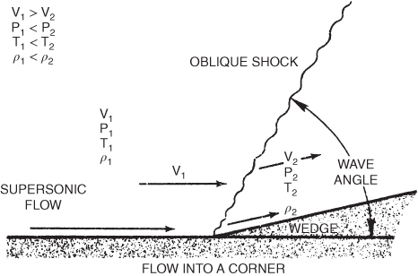
Figure 16.13 Formation of an oblique shock wave.
The airflow next to the horizontal surface must change direction when the wedge is encountered. It does this and assumes the direction of the arrow V2. This sudden change in direction, as the air particles turn into the path of other particles, V1, traveling in the horizontal direction, produces a shock wave at an oblique angle to the horizontal. The angle that the wave makes with the horizontal is called the wave angle. This is shown in Fig. 16.13.
The wave angle depends on the Mach number of the approaching flow and the angle of the wedge. It is the sum of the Mach wave angle and the wedge angle. The Mach wave angle is the angle whose sine is 1/M (are sin 1/M):

For example, if  and the wedge angle is 10°, then

The oblique shock wave is weaker than the normal shock wave, but it still is a shock wave and is wasteful of energy. As air passes through an oblique shock wave, its density, pressure, and temperature all rise and its velocity decreases. The principal difference is that the air remains supersonic behind an oblique shock wave, but it is always slowed to subsonic behind a normal shock wave.
Expansion Waves
The third kind of wave that occurs in supersonic flow is the expansion wave. Unlike the normal and oblique shock waves, the expansion wave is not a shock wave. In fact, the expansion wave is just the opposite of a compression wave. Density, pressure, and temperature all decrease as the air flows through an expansion wave. Air velocity increases through this wave and no energy is lost. Expansion waves form where the airstream turns around a convex corner, as on the trailing edge of some airfoils.
This is shown in Fig. 16.14. In flowing around the convex corner, the airstream makes an infinite number of minute direction changes until it has turned the corner and the flow direction is parallel to the downstream surface. The expansion wave takes place through a fan‐shaped area, as shown by the dashed lines in Fig. 16.14.
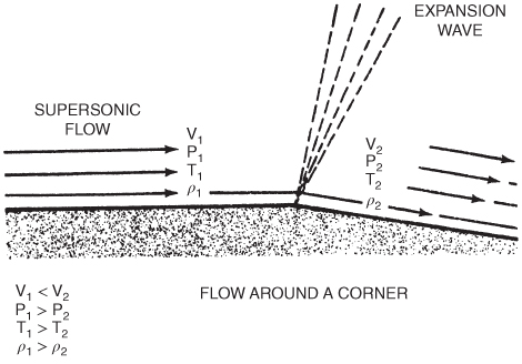
Figure 16.14 Formation of an expansion wave.
Shock waves, on the other hand, take place through a very narrow area. As the static pressure decreases through an expansion wave, lift is produced in this region. Subsonic flow could not negotiate a convex corner because the flow would separate from the wing. Supersonic flow, however, has a higher energy level and can turn these sharp corners by means of an expansion wave, without separation.
Characteristics of the waves are summarized in Fig. 16.15.
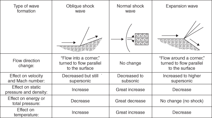
Figure 16.15 Summary of supersonic wave characteristics.
Aerodynamic Forces in Supersonic Flight
Aerodynamic forces are produced by differential pressures acting on the surfaces of a wing in an airstream. This is true whether the airstream is subsonic or supersonic. In supersonic flight sudden increases in pressure result when the airflow passes through shock waves. Static pressure drops when passing through an expansion wave, though gradually, while static pressure increases along with temperature when passing through oblique and normal shock waves. An expansion wave at a sharp corner produces a fairly rapid pressure drop, while an expansion over a curved surface will produce a gradual pressure drop.
Supersonic Airfoils
One type of supersonic airfoil is the double‐wedge airfoil shown in Fig. 16.16. This airfoil cannot be used subsonically because the air will become separated when it reaches the convex angles at the top and bottom of the wedges. It does have use in supersonic missiles that are boosted through the subsonic flight region.
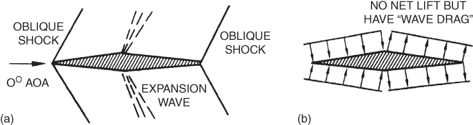
Figure 16.16 Double‐wedge airfoil in supersonic airflow: (a) wave pattern, (b) pressure distribution.
Figure 16.16a shows the wave pattern about a double‐wedge airfoil at zero AOA and thus zero lift in supersonic flight. Oblique shock waves, of the same strength, form at the top and the bottom of the leading and trailing edges. Behind these shocks the pressure rises but no net lift results. At the sharp corners at the 50% chord point expansion waves form, of the same strength. Lower pressures exist behind the expansion waves, but again the pressures on the top and bottom are equal in value and cancel each other. This is shown in Fig. 16.16b. The rearward components of the pressure arrows represent “wave drag” that exists even when no lift is being developed.
Consider the double‐wedge airfoil at a small positive AOA, as shown in Fig. 16.17a. The oblique shock waves are now not equal in strength. The shock wave at the top of the leading edge does not have to turn at as high an angle as it did at zero AOA and is now weaker. The pressure rise through the top shock is now lessened.
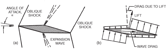
Figure 16.17 Double‐wedge airfoil developing lift: (a) wave pattern, (b) pressure distribution.
The reverse is true for the bottom leading‐edge shock. It is stronger and the pressure rise is greater than at zero AOA. The expansion waves at the midpoint corners are not of equal strength at a positive AOA. The top expansion is now greater, because the angle to be turned is greater than it was at zero AOA. The pressure decrease is also greater on the top. The opposite reasoning applies to the bottom expansion wave, and the pressure decrease behind the bottom expansion wave is lessened. Net lift is now being developed. The pressure distribution is shown in Fig. 16.17b.
To avoid the subsonic problems of the double‐wedge airfoil, another supersonic airfoil section is used. This is called the circular arc or biconvex airfoil and uses two arcs of circles to define its shape. With sharp leading edges the bow wave attaches easily. This airfoil develops shock waves at the leading and trailing edges, but because there are no sharp angles at the midchord point, no concentrated expansion wave occurs at that point. Instead, a continuous expansion wave, from the leading edge to the trailing edge, forms on the top and bottom airfoil surfaces. A symmetrical circular arc airfoil produces no net lift at zero AOA because the waves are symmetrical. But at positive AOA the shock wave on the top leading edge is weaker and the top expansion wave is stronger than the corresponding waves on the bottom of the airfoil. Thus, positive lift is created as shown in Fig. 16.18. The center of pressure and the aerodynamic center are both at the same position for both the double‐wedge and the circular arc airfoils. This position is at the 50% chord point. Even though the circular arc airfoil can be flown at subsonic speeds, it does not develop a high value of CL(max), the airfoils need to be as thin as possible, and it is not practical at slow speeds, thus takeoff and landing speeds are high.
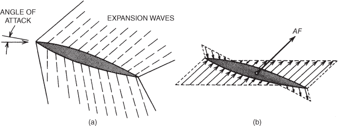
Figure 16.18 Circular arc airfoil in supersonic flow: (a) wave pattern, (b) pressure distribution.
Wing Planform
Earlier in this chapter we discussed the use of sweepback as a means of increasing Mcrit for subsonic aircraft. This same principle has other advantages for supersonic aircraft as well. In addition to increasing the force divergence Mach number, sweepback also reduces the amount of CD increase. This is shown in Fig. 16.19. The increase in drag coefficient is both delayed and reduced in value by sweepback.
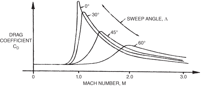
Figure 16.19 Effect of wing sweep on CD.
It is also interesting to compare straight wings (0° sweep) with swept wings. Note that the straight‐wing and the swept‐wing curves cross at some Mach number greater than 1.0. For the 45° wing they cross at about  . This means that at this speed both wings would have the same drag and at higher speeds the straight wing actually has less drag. Therefore, for high‐supersonic aircraft the straight‐wing configuration may be desirable. Of course, at speeds lower than the crossover point, the advantage is with the swept‐wing aircraft.
In our discussion of the formation of oblique shock waves we limited our analysis of Mach wave angle to two‐dimensional flow. In reality, the pressure disturbances radiate outward in all directions, like expanding spheres. Thus, instead of a Mach wave we have a Mach cone. This is shown in Fig. 16.20.
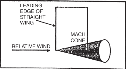
Figure 16.20 Mach cone.
Another advantage of sweep is that it places the wing within the Mach wave (cone) of the aircraft. This allows subsonic airfoil sections to be used for supersonic flight. Using subsonic airfoils is desirable because they develop higher CL(max) values and thus reduce takeoff and landing speeds.
Consider a Mach wave that is generated at the wing root as in Fig. 16.21. The air is supersonic ahead of the Mach wave and it is also supersonic in the direction of flight behind the Mach wave. The component of air behind the Mach wave that is perpendicular to the Mach wave will, however, be subsonic. If the wing is swept back so that its leading edge is behind the Mach wave, it will be flying in a subsonic flow and thus can use a subsonic airfoil section.
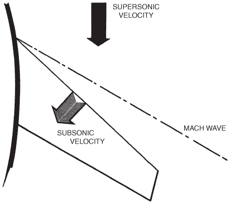
Figure 16.21 Swept wing in supersonic flight.
Area Rule Drag Reduction
Experiments in wind tunnels showed that bodies with sudden changes in cross‐sectional area produced more drag than similar bodies with gradual changes in area, especially approaching Mach 1. This increase in primarily wave drag resulted in a need for additional thrust in order to push through the transonic range and beyond. A large increase in the cross‐sectional area occurs at the wing root where the wings attach to the fuselage. By reducing the fuselage area at this point, the total area was enlarged gradually and drag was reduced. At the trailing edge of the wing the area of the fuselage was again increased to compensate for the loss of wing area. This results in the “coke bottle,” or wasp waist, shape of the fuselage, first used on aircraft like the F‐102. Originally used on fighter aircraft design, this method is no longer used because it is not cost‐effective.
High‐Speed Control Surfaces
Control surfaces on an aircraft are separated into primary and secondary controls, as seen in our discussion early in this textbook. The primary controls maneuver the aircraft around the three axes: lateral (elevator/stabilator), longitudinal (ailerons), and vertical (rudder). Secondary controls include high‐lift devices like flaps and slats, as well as other devices like spoilers. Wings designed for high‐speed flight also need to be maneuverable at slower speeds, especially when landing or taking off, and quite often to meet a certain mission requirement. Leading edge flaps and slats assist the aircraft at slower speeds and produce the CL needed during slow‐speed flight. Due to the streamlined nature of some aircraft, slowing down (especially when going down) can be an issue, so spoilers act as speed brakes to help reduce airspeed. Some aircraft have multiple types of spoilers; some are used in flight while others are used on the ground (and in flight). Since many jet aircraft have small ailerons, spoilers work together with the ailerons to provide proper roll control minimizing the effect of the forces of the ailerons on the wing. At higher speeds, some spoilers can be used instead of ailerons, as when an aircraft wants to roll right the spoiler lifts on the right side instead of the aileron, disrupting lift and increasing drag causing the aircraft to roll to the right. Finally, it is also common to see two sets of ailerons on an aircraft, inboard high‐speed ailerons and outboard low‐speed ailerons. Once an aircraft has cleaned up the aircraft after takeoff, the outboard ailerons lock and the inboard ailerons provide roll control.
Many newer aircraft incorporate elevator/aileron computers (ELACs) as well as spoiler/elevator computers (SECs), which control the movement of the elevators and ailerons and automatically compute the correct input of spoilers and yaw damping. Flight augmentation computers (FACs) compute the maximum operating limits for the aircraft, including wind shear and speed information for the cockpit displays. In addition, FACs also control yaw damping and the rudder to maintain turn coordination. All movable control surfaces became integral to high‐speed flight when, during early attempts to break the sound barrier, the aircraft did not have the design features found in more modern aircraft and the results were disastrous. To attain the required speed, the aircraft had to be put into a steep dive. When the aerodynamic center shifted to the 50% C location, the aircraft's center of gravity was ahead of the aerodynamic center. This created a stable dive condition that could not be overcome with the elevators, and often the aircraft continued in the dive until it hit the earth. The elevators were constructed in the conventional manner, as shown in Fig. 16.22. The control forces were limited to the small elevator itself and could not influence the flow about the horizontal stabilizer due to the shock wave that formed at the junction of the horizontal stabilizer and elevator as also shown in Fig. 16.22. The amount of force that the pilot could exert was also limited, because no power assist controls were available.
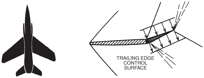
Figure 16.22 Subsonic control surface.
As the state of the art progressed, all moving control surfaces, as shown in Fig. 16.23, were developed, as were fully powered, irreversible control systems. Much more control was then available, and pitch control was no longer a problem. Many large, transport‐category aircraft today incorporate a variable incidence horizontal stabilizer to handle most of the trim control of the aircraft in pitch, with the smaller elevator taking care of the rest.
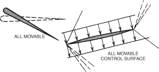
Figure 16.23 Supersonic control surface.
Supersonic Engine Inlets
The compressor blades of a turbine engine can be made to operate either subsonically or supersonically, but not both. The necessity for slow‐speed flight, as well as supersonic flight, rules out the use of supersonic flow in the compressor. Therefore, the flow must be slowed to subsonic when the aircraft is flying supersonically. This can be done only by the airflow passing through a normal shock wave.
The Mach number behind a normal shock wave is approximately 1/M, where M is the Mach number ahead of the shock. If the flight Mach is only slightly above 1.0 this is no problem, and a normal shock inlet such as shown in Fig. 16.24 can be used.
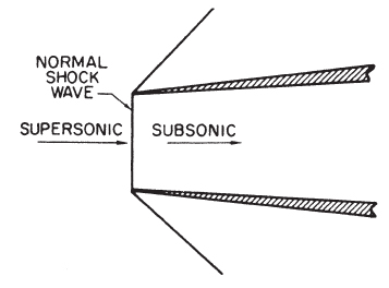
Figure 16.24 Normal shock engine inlet.
As the flight Mach number is increased, the reduction in airspeed in the normal shock wave becomes greater, the intensity of the shock increases, and the energy loss in the shock wave is increased. To reduce this energy loss an oblique shock inlet is used. This type of inlet may use a “spike” or a “ramp,” which causes oblique shock waves to form. When air passes through an oblique shock wave its velocity is reduced but remains supersonic. The energy lost in passing through an oblique shock is much less than that lost in passing through a normal shock. Often the air is slowed by a series of oblique shocks, each slowing the air until the air velocity is only slightly supersonic; the air is then passed through a weak normal shock.
Single and multiple oblique shocks formed by spike‐type inlets are shown in Fig. 16.25. The Mach cone angle varies with the flight Mach number, so for proper position of the shock waves, the spike (or ramp) must be adjustable in flight.
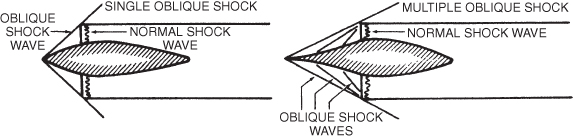
Figure 16.25 “Spike” oblique shock engine inlets.
Aerodynamic Heating
The temperature of the air in the stagnation area of the leading edge of the wing, at the nose of the aircraft, at the leading edges of the stabilizers, and at other stagnation points of an aircraft is shown in Fig. 16.26. The effect of aerodynamic heating on the tensile strength of structural alloys is shown in Fig. 16.27. These figures help illustrate the vast difference in problems of structural strength in designing a Mach 3 supersonic transport aircraft as compared to a Mach 2 SST. The stagnation temperature in the stratosphere is about 250° F for the Mach 2 aircraft and about 700° F for the Mach 3 SST. Comparing the tensile strength of aluminum alloy at these temperatures shows that at 250°F about 80% of the room temperature tensile strength remains, but at 700°F less than 10% of the room‐temperature strength remains. Clearly, it is not feasible to make leading edges out of aluminum alloy for a Mach 3 aircraft.
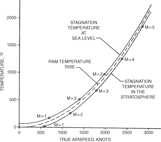
Figure 16.26 Stagnation temperatures.
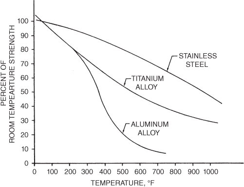
Figure 16.27 Effect of temperature on tensile strength of metals after half‐hour exposure.
Computational Fluid Dynamics and Computer‐Aided Design
Computational fluid dynamics (CFD) and computer‐aided design (CAD) are now standard design approaches to any new aircraft or aircraft component. Safety should always be the driving force in aircraft design, followed of course by mission requirements, regulatory mandates, and production costs. CFD and CAD allow modeling and testing of new aircraft and component designs before wind tunnel tests are initiated and ultimately flight testing. By using computer fluid modeling and design, engineers are able to narrow down the best fuselage and wing shape for the aircraft mission. When designing an aircraft for supersonic flight, calculating the critical Mach number, as well as the effects of drag as the aircraft accelerates through transonic flight, CFD and CAD allow areas of inefficiency to be noted before expensive wind tunnel tests are initiated. An aircraft that is able to exceed Mach 1 may also need to be highly maneuverable in the subsonic region for air‐to‐air combat, and then perform a landing on an aircraft carrier. Engine placement on a wing may greatly affect interference drag and the position of the aircraft's CG, or a design may call for Vertical Takeoff and Landing (VTOL) ability. By incorporating CFD and CAD, the above mission requirements can be designed in to the aircraft, and expensive modifications can be avoided while allowing wind tunnel and flight testing to be more efficient.
Specifically, CFD uses mathematics, physics, and software to visualize how a gas or liquid affects an object as it flows around the object, allowing an engineer to monitor the changes in temperature, pressure, density during the process. A three‐dimensional model is created to help better design integral aircraft components like engine nacelle design and airfoil shapes. An airfoil shape that may initially work well for supersonic flight may not have the structural integrity to sustain required engine or weapon placement. As the research continues into supersonic and hypersonic flight, CFD will be used extensively to understand what materials can withstand the aerodynamic heating at the stagnation points associated with these speeds. During supersonic missile development, CFD contributes to more efficient designs allowing for greater speed and more maneuverability, as well as solving for complex flow and heat transfer problems. As the proliferation of unmanned aerial vehicles (UAVs) make their way into the civilian market from the air defense sector, CFD will continue to be used to meet the regulatory challenges implemented by the FAA as well as the demands from commercial operators.
Within commercial transport category aircraft design, CFD was instrumental to the design of the flight deck of the Boeing 757 and 767 common‐type rating. Though the aircraft may appear remarkably different from the outside, the flight decks were designed so pilots could make the change from one flight deck to another with minimal difficulty. Aerodynamic drag was reduced around the flight deck of the 757, as was noise, through the use of CFD as local areas of supersonic flow were eliminated. Engine placement, engine nacelle design, and the continued growth in the composite materials industry in order to maximize fuel reduction all begin with CFD.
SYMBOLS
| a | speed of sound (knots) |
| a0 | speed of sound at sea level, standard day |
| M | Mach number (dimensionless) |
| VMO | Maximum operating speed (knots) |
| MMO | Maximum operating speed (Mach) |
| θ (theta) | Temperature ratio = T/T0 |
| μ (mu) | Mach wave angle (degrees) |
EQUATIONS
- 16.1

- 16.2

- 16.3

PROBLEMS
- The speed of sound is an important factor in high‐speed flight because
- Mcrit occurs at
 .
. - the pressure waves generated by the plane move at sonic speed.
- shock waves form when local air velocities are supersonic.
- Both (b) and (c)
- None of the above
- Mcrit occurs at
- The speed of sound depends on the air density, pressure, and temperature.
- True
- False
- Critical Mach number, Mcrit, is the aircraft's speed when
- it goes supersonic.
- the airflow first reaches sonic speed.
- shock waves form.
- Both (b) and (c)
- None of the above
- After passing through a normal shock wave, airflow is
- subsonic.
- not changed in direction.
- heated up.
- increased in pressure and density.
- All of the above
- Airflow passing through an oblique shock wave remains supersonic but changes in direction.
- True
- False
- Transonic flight problems may include
- force divergence.
- increase in CD.
- decrease in CL.
- tuckunder.
- buffet.
- control surface buzz.
- loss of control effectiveness.
- All of the above
- All except (a)
- Above about Mach 2, the straight‐wing aircraft has a lower drag than a 60° swept‐wing aircraft.
- True
- False
- Mach wave angle changes with airspeed as follows:
- It decreases as airspeed increases.
- It increases as airspeed increases.
- It remains the same with airspeed changes.
- All supersonic aircraft have circular arc or biconvex supersonic airfoils.
- True
- False
- Airflow passing through an expansion wave
- speeds up.
- increases the energy of the airstream.
- decreases the temperature of the air.
- Both (a) and (c)