Chapter 12
Slow‐Speed Flight
Throughout the history of aviation, the slow‐speed region of flight has been the most hazardous. During takeoff, landing, instrument approaches, and go‐arounds the aircraft is forced to move in “slow flight,” so recognizing the hazards during this time is instrumental to understanding aircraft control characteristics at these slower speeds. Outside of these normal times of slow flight, the aircraft may be maneuvered for various reasons 3–5 knots above stall speed during level, climbing, or descending flight; this controlled maneuvering is also referred to as slow flight. During flight training, applicants are required to maneuver in slow flight to demonstrate mastery of aircraft control at these slow airspeeds. If an aircraft slows to minimum controllable airspeed, any additional increase in angle of attack or load factor, or reduction in airspeed will result in a stall. Failure to understand how an aircraft responds to control inputs at these slower speeds, and the proper recognition and recovery from inadvertent spins, continue to result in fatal aircraft accidents.
Different aircraft designs result in varied aircraft responses to slow flight; the reasons for this are quite different for straight‐wing aircraft and for swept‐wing aircraft. Examination of the coefficient of lift curves for each type of aircraft will help explain some of these differences.
Figure 12.1 shows the lift versus AOA curves for a straight‐wing, propeller‐driven aircraft and a swept‐wing, turbojet aircraft. Four differences can be seen from these curves:
- The straight‐wing aircraft has a higher value of CL. Recall the basic lift equation

It can be seen that if the lift equals the aircraft weight, stall speed, VS, will be a minimum when the value of the lift coefficient is a maximum,
 . The higher the value of CL(max), the lower the stall speed will be. This means that the straight‐wing aircraft has a lower stall speed for the same weight and wing area.
 - The swept‐wing aircraft must fly at a higher AOA to achieve maximum lift.
- There is a sudden reduction of CL for the straight‐wing aircraft at stall, but not for the swept‐wing aircraft.
- The straight‐wing aircraft is more sensitive to AOA changes.
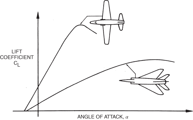
Figure 12.1 Effect of sweepback on  curves.
STALLS
We discussed in earlier chapters that a stall occurs when the boundary layer separates from the wing, the critical angle of attack has been reached, and the wing is no longer producing enough lift to sustain level flight. Pilots practice intentional stalls in order to recognize the conditions that produce stalls, characteristics of the aircraft approaching stall, and the proper recovery technique to avoid worsening the stall (secondary stall) and minimizing altitude loss while maintaining positive aircraft control.
However, an aircraft does not need to be in slow flight in order to enter a stall as stalls can occur at any airspeed, altitude, and configuration. The pilot of an aircraft in a steep dive can pull abruptly back on the stick and exceed the critical angle of attack at a speed well above VS0. The critical AOA does not change for a given aircraft, regardless of airspeed, weight, or altitude. As we will see in the next chapter the stall speed also increases once an aircraft enters a level flight turn. Still the aircraft will stall at the same AOA regardless of an increase in load factor. Back pressure is applied to the stick or yoke during a level turn, lift increases, as does the wing AOA, and eventually a stall will be produced if back pressure continues to increase. Once an aircraft stalls, the wing design as well as the placement of the CG greatly influences the recovery technique and the altitude loss suffered.
Regardless of the type of aircraft, type of wing planform, or type of stall, the approach to a stall will always display certain uniform characteristics. Pilots must recognize these characteristics in order to initiate recovery procedures before the stall develops or loss of altitude has begun. Inappropriate attention to managing the automation (Colgan Flight 3407), incorrect response to instrumentation error and stall indications (Air France Flight 447), and many other high‐profile accidents, in addition to hundreds of general aviation accidents, continue to show that pilots are still not responding correctly to impending stall indications. While improved automation and artificial stall indicators do raise awareness of an oncoming stall, the basic senses of sight, sound, and feel still prove to be a valid form of warning for an impending stall. During slow flight, feel continues to be the best indicator that the aircraft is approaching a stall and corrective action needs to immediately be applied. The pilot may sense the aforementioned mushy controls, and sense a change in direction of the aircraft. At various speeds the pilot may feel vibration in the controls, or a feeling of buffeting in the flight controls. Hearing also plays an important role. In a fixed‐pitch propeller aircraft the propeller has an audible change in rpm should additional load be placed on the propeller during a climb, and the sound of the air flowing around the aircraft decreases as the aircraft slows toward a stall. In each of these examples, pilot experience plays a vital role in how soon the indicators of an impending stall are recognized, and the correct recovery technique to begin a smooth transition back to normal flight.
Stall Patterns
For purposes of this discussion, let us compare fighter aircraft in each category. The basic principles of the stall were discussed earlier; now it is important to discuss the stall patterns of different wing designs as well as the advantages and disadvantages of generic wing shapes.
The lift distribution in the spanwise direction of an ellipse is shown in Fig. 12.2. The lift is zero at the wingtips and increases elliptically, with the maximum lift occurring at the wing root. If the wing area is exactly proportional to the lift at all points on the wing, the local wing loading will be a constant value everywhere on the wing. Stall of a wing will occur where the ratio of local lift coefficient, C1, to the wing lift coefficient, CL, is highest. If the wing planform area is also elliptical, the local wing loading will be constant. This is shown by the value of  in Fig. 12.3. Thus, the entire trailing edge of an elliptical planform wing will stall at the same time. The elliptical wing is considered to be the most efficient planform and was used with much success on the British Spitfire during World War II. Structurally, the elliptical wing is difficult to manufacture, so it is not widely used.
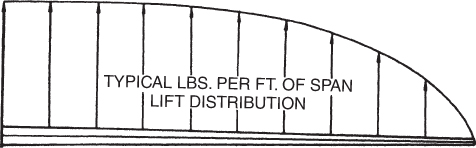
Figure 12.2 Spanwise lift distribution.
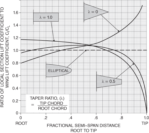
Figure 12.3 Wing spanwise lift distribution.
The straight wing is usually rectangular or it has a slight taper. The wing area near the wingtip is large compared to the lift in that area, and the wing loading is, therefore, low. Figure 12.3 shows that the value of  approaches zero near the wingtip for the rectangular wing. The maximum wing loading is at the wing root. Stall will, therefore, start at the trailing edge of the wing root and then spread outward and forward as the stall progresses, as shown in Fig. 12.4.
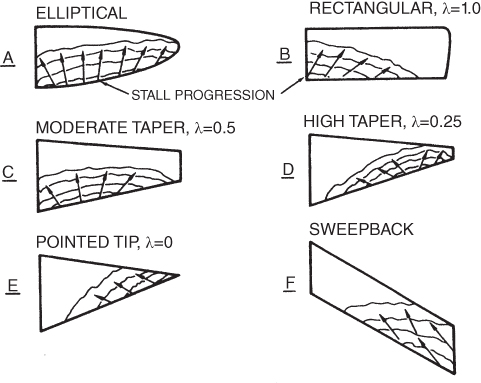
Figure 12.4 Stall patterns.
Straight‐wing aircraft, with stall starting at the roots, seem to have advantages over swept‐wing aircraft, as far as stall characteristics are concerned. First, there is more adequate stall warning, caused by the separated air buffeting the fuselage. Second, the ailerons of the straight‐wing aircraft are not enveloped in the stalled air until the stall has progressed outward from the wing roots, compared to the relatively early envelopment from tip stalling of the swept wing.
Swept wings have more taper, with the extreme being the delta wing, which has a taper ratio of zero. The delta wing's area at the tip is very small, and the wing loading is very high. Stall starts where the wing loading is highest, so the stall starts at the wingtip and progresses inboard and forward. The high tip wing loading can be seen from the values of  in Fig. 12.3. The stall pattern is shown in Fig. 12.4.
- The lack of a sharp stall point on the CL curve of a swept‐wing aircraft makes it nearly impossible to stall it under normal low‐speed flight conditions so many swept‐wing aircraft are usually equipped with stall warning devices to compensate for the lack of buffet warning. However, this does not mean that the low‐speed region is safe for swept‐wing aircraft.
- In Chapter 5 we saw that induced drag was very high at low airspeeds. Induced drag is also greater with aircraft having low aspect ratios. Sweeping the wings reduces the span and effectively increases the chord. Aspect ratio is the span divided by the average chord, so swept‐wing aircraft, with the same wing area, have lower values of aspect ratio. The high drag existing at low airspeeds was evident in the comparison of thrust‐required curves of the swept‐wing jet aircraft to the power‐required curves of propeller‐driven straight‐wing aircraft.
Stall Recovery
Proper stall recovery procedures may vary widely depending on type of aircraft, the amount the aircraft is “stalled,” and distance from terrain. As always the pilot should refer to the manufacturer's recommended recovery procedures, and practice various stalls and stall recovery during all refresher training. Since a stall occurs at the critical angle of attack, regardless of the aircraft and flight attitude, the first corrective action should be to reduce the angle of attack. Usually this means a reduction in stick (yoke) pressure to lessen AOA, or a reduction in back‐pressure in a high‐G maneuver. Since a stall may occur in any attitude, “lowering the nose” is not the correct response unless the aircraft is in an upright attitude in relation to the ground. In some cases forward pressure may be required, but only enough to reduce the excessive angle of attack and not enough to produce excessive nose‐low attitude (during normal upright attitude recoveries) and negative G‐load on the wings. If too much forward stick pressure is used altitude loss may be extreme, jeopardizing recovery before impact with terrain.
While reducing the angle of attack will begin the process of recovery from a stall, power may be required to assist with minimizing altitude loss and further the decrease in angle of attack. If the aircraft is already at full power, in most cases the power should be maintained to assist with recovery, but managed appropriately so that the aircraft does not overspeed or exceed the load factor limitations. Depending on altitude and type of stall experienced, the pilot should then regain straight‐and‐level flight at normal airspeed until the pilot has verified that the aircraft is under control.
During the stall and stall recovery, care should be taken to avoid excessive roll and yaw. As we learned, swept‐wing aircraft stall first at the wingtip, and then the stall progresses inward and forward. If the ailerons are located in the aerodynamically dead air, the pilot will have limited roll control should the aircraft become unstable around the longitudinal axis. During practice stalls in a single‐engine propeller aircraft, banking during stalls is common place, and even advised during training in order to demonstrate confidence to the pilot. Due to the rectangular wing planform, the stall initiates at the wing root and progresses outward and forward, allowing the pilot positive roll control during the stall and recovery. During some stalls in a single‐engine aircraft with high power settings, right rudder application may be required to maintain coordinated flight. Left aileron may also be required to prevent overbanking, so aileron control during this time is very important. If the stall is allowed to continue until a “full‐break,” a wing drop may occur. If the pilot attempts recovery by rolling in the opposite direction, the downward deflecting aileron on the low wing would produce a greater angle of attack, thus increasing the drag on that wing and complicating the situation. The wing tip may now become stalled, the aircraft begins a yaw in that direction, and a spin could develop if the angle of attack is not reduced. Should yaw control not be properly maintained throughout the stall and recovery, a spin could develop, resulting in additional altitude loss.
Power‐Off/Power‐On Stall
Power‐off stalls are most commonly practiced to simulate approach to stall during a landing event. The aircraft is configured for landing with flaps and landing gear deployed, and normal VREF speed is achieved. As the nose is lowered to normal approach attitude, it is once again raised to an attitude to induce a stall. The wings should be held level to prevent banking, and directional control maintained by coordinated use of the rudder. When the critical angle of attack has been reached, the nose should be lowered to reduce the angle of attack and the recovery procedures initiated. On single‐engine propeller aircraft, right rudder may be needed to maintain coordination as power is applied and the nose is raised to minimize altitude loss. Gear and flaps are retracted per the manufacturer's procedures, and the airplane is trimmed for straight‐and‐level flight (Fig. 12.5).
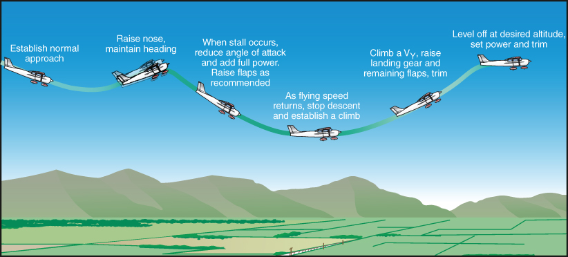
Figure 12.5 Power‐off stall and recovery.
U.S. Department of Transportation Federal Aviation Administration, Airplane Flying Handbook, 2004
A power‐on stall is usually practiced to simulate an inadvertent stall during takeoff or climb. Takeoff gear and flap settings are utilized and depending on the aircraft type full power may be used throughout the power‐on stall, though usually a percentage of full power is more commonly utilized to avoid excessive nose‐high attitudes. To begin the maneuver the aircraft slows to liftoff speed while in level flight to reduce the likelihood of extreme nose‐high attitudes being reached during the setup for the stall. Once the target airspeed has been reached the appropriate power is set and the nose is smoothly raised with aft stick until the critical angle of attack is reached. Care must be taken when demonstrating this maneuver in a single‐engine propeller aircraft, as increased right rudder must be used to compensate for the left‐turning tendencies experienced at high power, high angle of attack attitudes (left‐turning tendencies are discussed later in the textbook). If proper directional control is maintained with the rudder, the aircraft will stall wings level and the proper recovery technique should be initiated. Usually once the nose is lowered and the excessive critical angle of attack is reduced, the aircraft will recover and the nose can once again be raised in order to minimize altitude loss. As with a power‐off stall, if the aircraft experiences a wing drop at the moment of full stall, opposite aileron should not be applied because the stall may become aggravated and an incipient spin develop. Opposite rudder to the wing drop must be applied as soon as possible, if the nose of the aircraft begins to yaw to the left and the left wing drops, immediate application of the right rudder is required. Use of opposite rudder is required to correct any wing drop.
Often power‐on stalls are practiced only until imminent stall is reached, where the pilot is allowed to recover when one of the stall characteristics is recognized and the maneuver is terminated. At any time during the maneuver should an unsafe condition develop, one of the pilots should call “knock‐it‐off” and recovery procedures should be initiated.
A variation of the power‐on stall can occur during an elevator trim stall. If an aircraft is trimmed for landing, or for best glide speed during a simulated emergency descent, the nose may pitch to an extreme nose‐high attitude when full power is applied for a go‐around or missed approach. Heavy stick forces may be encountered as the pilot tries to maintain a safe pitch attitude below the critical angle of attack until the trim forces can be reduced.
During training events for power‐on and power‐off stalls, pilots should periodically practice secondary stalls to familiarize themselves with the conditions that cause a secondary stall, and the proper control actions to recover and prevent additional secondary stalls. A secondary stall results when the pilot fails to apply the correct recovery procedures from an initial stall, usually due to abrupt control movement as the nose drops during stall recovery (Fig. 12.6). If the stick is pulled back too abruptly, the aircraft will once again approach the critical angle of attack and experience another stall, which in extreme cases can lead to multiple secondary stalls. Multiple secondary stalls are sometimes referred to as “falling leaf stalls,” when an excessive angle of attack is maintained with aft stick pressure and rudder is used to maintain coordination and prevent excessive wing drop.

Figure 12.6 Secondary stall due to improper stall recovery.
U.S. Department of Transportation Federal Aviation Administration, Airplane Flying Handbook, 2004
Accelerated Stall
An accelerated stall occurs at a higher airspeed than is usually experienced by a pilot during “normal” stall training. Accelerated stalls may occur when the pilot makes an abrupt control movement, resulting in the wing exceeding the critical angle of attack at higher than the usual published stall speeds. Accelerated stalls are in essence a “G‐induced” stall, as they occur at load factors greater than one, which is the load factor for stalls during normal student training in light aircraft. During turns when excessive wing loading is experienced, a higher stall speed will occur, often surprising the inexperienced pilot. Corrective actions should be immediately applied, usually beginning with reducing aft stick pressure and leveling the wings. Accelerated stalls can be more insidious than power‐off and power‐on stalls, and occur with much less warning. Often pilots are caught unaware of the impending accelerated stall, resulting in loss of directional control and improper yaw correction, and in extreme conditions a spin can occur. Pilots should practice accelerated stalls during training and recognize the importance of design maneuvering speed and load factor. More on this topic will be discussed in Chapter 13.
Cross‐Control Stall
A cross‐control stall is a type of accelerated stall that deserves special attention due to the common occurrence of the conditions that set up this type of stall, and the fact that it usually occurs in the traffic pattern when the aircraft is close to the ground. The insidious nature of this stall can result in little to no warning of the oncoming stall, immediate spin entry due to excessive yaw, and little time for recovery by the unsuspecting pilot. A common situation begins when the pilot overshoots the base‐to‐final turn and realizes the aircraft is not aligned with the runway centerline. Unwilling to steepen the bank angle of the aircraft, the pilot swings the longitudinal axis of the aircraft toward the runway with the rudder increasing the rate of the turn. As the speed of the outer wing increases, the lift increases and an increased roll develops on the outer wing. To counteract this, the pilot applies the opposite aileron, which as we have discussed exacerbates the situation due to the downward deflecting aileron on the low wing. Since this action lowers the nose even more toward the ground, the pilot instinctively applies back pressure on the stick, raising the nose. The IAS now begins to decrease due to the increase in drag; simultaneously the stall speed begins to increase and within seconds, depending on the severity of the situation, the IAS and stall speed meet with little warning.
Due to the excessive yaw, the wing may violently drop unexpectedly and the aircraft roll inverted. Since this occurs close to the ground, even using proper recovery techniques there may not be sufficient time and altitude to recover. Proper recognition and avoidance of the cross‐control stall is the only reasonable course of action.
REGION OF REVERSED COMMAND
Because the high drag on jet aircraft at low airspeeds is so important, a discussion of the region of reversed command is warranted. Most pilots are familiar with this flight region as the “backside of the thrust curve” or, incorrectly, as the “backside of the power curve.” This last expression is correct only when propeller aircraft are being discussed. Propeller aircraft are not hindered by a lack of power in the low‐speed region, so only jet aircraft and thrust‐required curves are considered here.
A typical thrust‐required curve for a turbojet aircraft in the dirty configuration is shown in Fig. 12.7. Minimum drag occurs at the  point. For this aircraft these figures are 2400 lb thrust required at 160 knots TAS. All airspeeds greater than that for minimum drag are said to be in the region of normal command. In this region added thrust must be supplied if greater airspeed is desired. To increase the airspeed to 200 knots, the pilot must add throttle until the engine(s) produce 2750 lb of thrust.
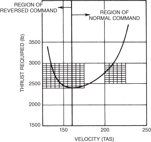
Figure 12.7 Regions of normal and reversed command.
In the region of normal command, thrust is directly proportional to velocity. All airspeeds below that for minimum drag are said to be in the region of reversed command. In this region, the thrust required to fly the aircraft is inversely related to the airspeed. The slower the aircraft flies, the greater the thrust required. At an airspeed of 140 knots, for instance, the Tr is 2750 lb, the same as was required at 200 knots.
It can be reasoned that “if more thrust is required to fly slower, then to slow down the pilot should add throttle.” This, of course, is not true. The fallacy of this statement lies in the fact that, at any stabilized airspeed, the thrust available equals the thrust required, and adding throttle produces a thrust excess. This excess will cause the aircraft either to climb or to accelerate. The correct statement should be: If, for any reason, the aircraft should be slowed down, more thrust is required to maintain altitude at that airspeed.
Take the case of an aircraft flying at minimum drag. This is 160 knots for the aircraft in Fig. 12.7. The Tr is 2400 lb, and the Ta must also be 2400 lb for stabilized flight. There is no excess thrust, so the aircraft cannot climb under these conditions. To slow the aircraft, the pilot has several alternatives: (1) increase the drag by using speed brakes, extending the flaps, or by lowering the landing gear; (2) retard the throttle, thus reducing thrust; (3) increase the AOA by back pressure on the control stick.
Let us examine these alternatives in more detail. Increasing the drag is certainly a viable method of slowing the aircraft. That is why speed brakes were invented. However, speed brakes, flaps, and lowering the gear usually result in rapid changes in airspeed, so let's examine how we could slowly and gradually reduce the airspeed.
Reducing the throttle results in a thrust deficiency. At any stabilized flight airspeed, a thrust deficiency results in a rate of sink (ROS). This can be seen by an adaptation of Eq. 6.6, where Ta is now subtracted from D ( ) in order to provide a positive ROS, which is the same as a negative ROC.
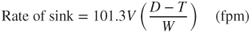
The pilot who elects to slow the aircraft by this method cannot maintain altitude. Any attempt to increase AOA to compensate for less thrust will merely decrease the airspeed and increase the drag. This results in an even greater thrust deficiency and greater rate of sink.
The third method of slowing the aircraft is to increase the AOA. In our study of the basic lift equation, we made a point of the fact that the AOA controlled the value of the lift coefficient, and this in turn controlled the airspeed. We said, Angle of attack is the primary control of airspeed in steady flight.
Let's see how this works. The pilot pulls back on the control stick and thus increases AOA. Lift coefficient is increased, airspeed is reduced, and drag is increased. A deficiency now exists in thrust and a sink rate will develop. So, the pilot must add throttle to maintain altitude. This can be a smooth coordinated method of slowing the aircraft without loss of altitude and without excessive “throttle jockeying.”
Another example of using AOA to control airspeed is illustrated in Fig. 12.8. Suppose a pilot is flying an airplane having the Tr curve shown in Fig. 12.8 and the throttle is set to produce 3000 lb of thrust. For stabilized flight, the airplane must be at point A or at point B. At point A the airspeed is 210 knots, and at point B it is 135 knots. To climb the airplane from point A, the pilot can pull back on the control stick and increase the AOA. This will increase the CL and decrease airspeed. If this maneuver slows the aircraft to 200 knots, the thrust available is still 3000 lb, but the thrust required has dropped to 2750 lb. The aircraft now has an excess thrust of 250 lb and will be able to climb.
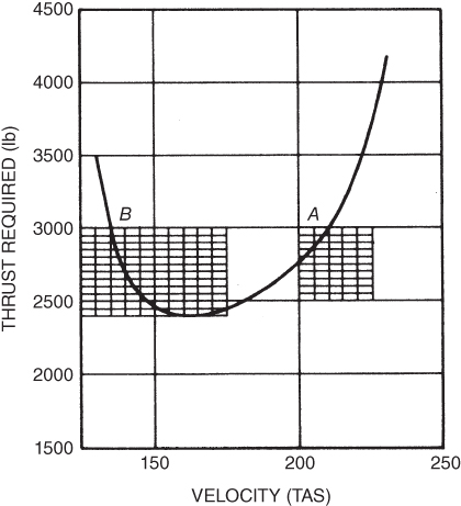
Figure 12.8 Constant airspeed climb. Stick or throttle?
Now, suppose the plane is at point B. To climb the aircraft the pilot pulls back on the control stick and increases the AOA. The airspeed will be reduced again, but this time the thrust required will be increased. If the airspeed is decreased to 130 knots, the thrust required will be about 3500 lb, for a thrust deficiency of 500 lb. The climb method that worked in the region of normal command will not work in the region of reversed command.
There is a method of climbing the aircraft that works at all airspeeds, and it is strongly recommended. Always control the airspeed with the stick. If the airspeed is held constant, thrust required will be constant. Climb is then controlled by the excess thrust, and the thrust available is determined by the throttle setting. So, throttle setting controls the rate of climb or descent in steady flight.
Flight in the region of reversed command cannot be avoided. Every takeoff and landing requires flight in this region. Pilots must be careful not to paint themselves into a corner, where drag is so high that enough thrust may not be available to overcome it. When the drag ( ) exceeds the thrust available (
 ) there is only one way to go—down.
SPINS
Intentional spins are prohibited in most light aircraft, but spins and spin recovery should be taught when possible as part of all pilot training. The statistics continue to show that pilots are not heeding the warnings of stall recognition, or failing to properly recover from a stall/spin situation. Spins are much more difficult to control in a jet aircraft, so they are not common practice. Actual spin recovery techniques vary for different aircraft, thus the discussion presented here is general in nature.
Spin Warning
For an aircraft to spin it must be near aerodynamic stall. Therefore, stall warnings must be heeded if spins are to be avoided. For most general aviation, light training aircraft spins are considered to have four stages: Entry, Incipient, Developed, and Recovery. During the entry stage the pilot introduces the conditions for stalled flight, whether accidentally or intentionally, then the incipient phase begins once the aircraft begins rotation and usually lasts 2–3 turns until the inertial and aerodynamic forces come into balance. Once in equilibrium, the airspeed and vertical speed are stabilized and the aircraft continues to rotate until the recovery process is initiated, the AOA is reduced below the critical angle of attack and rotation stops (Fig. 12.9).

Figure 12.9 Spin entry and recovery.
U.S. Department of Transportation Federal Aviation Administration, Airplane Flying Handbook, 2004
In our discussion of stalls earlier in this chapter we mentioned the advantages of the straight wing in providing stall warning to the pilot. When pilots of straight‐wing aircraft feel the buffeting, they merely have to reduce back pressure to avoid the possibility of a spin. Figure 12.10 shows how a straight‐wing aircraft stalls at the wing root first and how the stalled air envelops the tail and provides buffet warning to the pilot. At this point, the ailerons are still experiencing air flow and the pilot still has good lateral (roll) control.
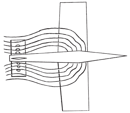
Figure 12.10 Stall hitting the horizontal tail.
Swept‐wing aircraft stall at the wingtips first, rather than at the roots. This is shown in Fig. 12.11. The stall warning here is much less than for the straight‐wing aircraft. Also, the ailerons are enveloped in the stalled air and become ineffective early in the stall–spin sequence. Stall warning devices are helpful in anticipating an incipient spin.
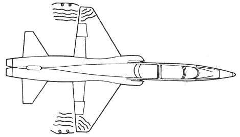
Figure 12.11 Swept wings stall at tips first.
Aerodynamic Characteristics of a Spin
The aerodynamic characteristics of a spin for a straight‐wing aircraft and those for a swept‐wing aircraft are quite different. The straight‐wing aircraft has CL and CD curves as shown in Fig. 12.12. If this type of aircraft is flying at an AOA at or above that for  and the aircraft is rolled to the right (and/or the right wing drops), the right wing is flying with a higher local AOA and becomes even more stalled. The left wing, on the other hand, moves upward and is flying with a lower local AOA and becomes less stalled, thus producing more lift. The right rolling motion of the aircraft is aided by the relative increase in lift of the left wing, and a yawing moment to the right is produced. These moments result in autorotation. This means that the aircraft will continue to roll and yaw without any input from the pilot. In addition to the aerodynamic forces acting on the aircraft, there are also inertia and gyroscopic effects that complicate the problem.
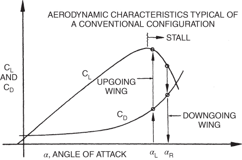
Figure 12.12 Aerodynamics of spin for straight‐wing aircraft.
The straight‐wing aircraft's spin is characterized primarily by the rolling motion with a moderate yaw. The attitude of the spin is about 40° or more, nose down. In straight‐wing aircraft, a stalled condition must exist before a spin can develop, but this is not true for a swept‐wing aircraft. The swept‐wing aircraft has CL and CD curves as shown in Fig. 12.13. Note that the CL curve does not have a well‐defined maximum lift point. When this type of aircraft is rolled at high angles of attack, only small changes in CL take place. In the swept‐wing aircraft there is no definite stall, and the wing autorotation contribution will be quite weak. The change in CD that occurs between the two wings, however, is substantial and a strong yawing moment is developed.
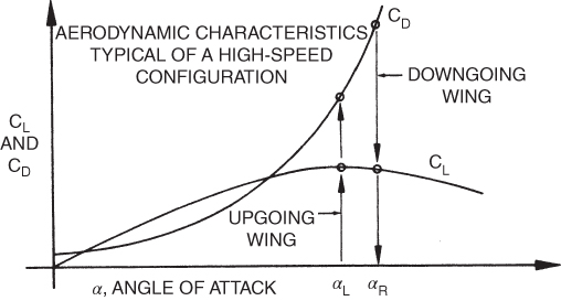
Figure 12.13 Aerodynamics of spin for swept‐wing aircraft.
Swept‐wing aircraft have low aspect ratios. The mass of the aircraft is distributed along the longitudinal axis of the plane rather than in the wings. As the yaw develops, during the spin, this mass distribution contributes to the inertial moments and tends to flatten the spin. This results in very high angles of attack and high sink rates.
This explanation is extremely simplified. Each part of the airplane affects pro‐spin or anti‐spin characteristics separately. Each model of airplane spins differently, and each will spin differently when the configuration of the aircraft is changed. Pilots must be familiar with the spin characteristics of their airplanes as described in the operator's handbook.
Spin Recovery
For those who accidentally enter a spin condition, disorientation and confusion in the direction of rotation can occur, especially if in instrument meteorological conditions (IMC) and flying solely by reference to instruments. Determining whether you are in a spin or spiral by looking at your airspeed indicator is paramount to begin recovery procedures. The most effective spin‐recovery technique for any aircraft is to follow the manufacturer's recommended recovery procedures.
In the absence of a published procedure the following technique is widely accepted for a typical spin recovery procedure:
- Reduce the throttle to idle.
- Position the ailerons to neutral.
- Apply opposite rudder to the direction of rotation.
- Apply stick (yoke) forward beyond the neutral position and hold (decrease AOA).
- Neutralize the rudder after rotation stops.
- Apply back pressure on the stick (yoke) until level flight (caution of secondary stall or excessive loads).
LOW‐LEVEL WIND SHEAR
Wind shear can be defined as a sudden and prolonged change in wind direction and/or speed, relative to an airplane's ability to accelerate. While the wind‐shear phenomenon can occur at altitude, it is most hazardous below 2000 AGL during approach, landing, and takeoff operations, so this discussion is limited to low‐level wind shear. Under unusual weather conditions, wind‐direction changes of 180° and wind‐speed changes as high as 50 knots have been observed.
We have been taught that wind cannot affect an aircraft in flight except for groundspeed and drift. This is true for steady winds or winds that change gradually, but it is not true when rapid wind changes occur. When the air velocity changes, the mass of the aircraft must be accelerated or decelerated, and this takes time. Slow‐accelerating airplanes will have more trouble recovering from wind shear.
Wind shears are caused by thunderstorm activity, weather fronts, and temperature inversions with strong winds above. Figure 12.14 illustrates a wind‐shear situation caused by a downdraft. At position 1 the aircraft encounters the outflow, then a degradation in performance occurs at position 2 when the headwind shifts to a tailwind and downdrafts become stronger. In position 3 the increasing downdrafts along with a strong tailwind cause the aircraft to descend, terminating in position 4 when the aircraft may or may not clear terrain as the tailwind continues. The downward air flow in this situation, commonly associated with a thunderstorm, is called a downburst, and when limited in size is more commonly referred to as a microburst. Studies have indicated that downdrafts in excess of 6000 fpm were encountered in strong microbursts. As a headwind or tailwind is shifted 180° the aircraft suffers a change in performance and may not be able to outclimb the strong downdraft. The downburst, specifically when microburst in size, is the most dangerous type of wind shear because it can force the airplane into the ground.
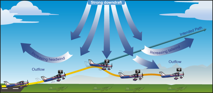
Figure 12.14 Wind shear caused by a downdraft.
U.S. Department of Transportation Federal Aviation Administration, Pilot's Handbook of Aeronautical Knowledge, 2008
When a downburst hits the ground, it is diverted outward. This creates horizontal air velocities known as headwind bursts, tailwind bursts, and crosswind bursts, depending on the position of the aircraft relative to the center of the thunderstorm. These are shown in Fig. 12.15, as viewed from above. The performance of an aircraft flying through these bursts is discussed in the next section.
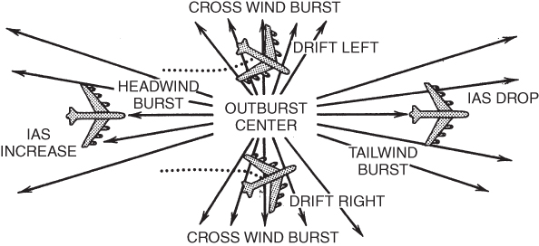
Figure 12.15 “Bursts” caused by a thunderstorm.
Another hazard associated with thunderstorms is called the gust front, which may precede a thunderstorm by as much as 15 miles. This is shown in Fig. 12.16. The slope of the gust front makes it impossible to determine when an aircraft will fly through it, especially when it is located in visual meteorological conditions (VMC) outside of precipitation. Aircraft at this point may be trying to beat the storm into or out of an airport and encounter the unexpected shear.
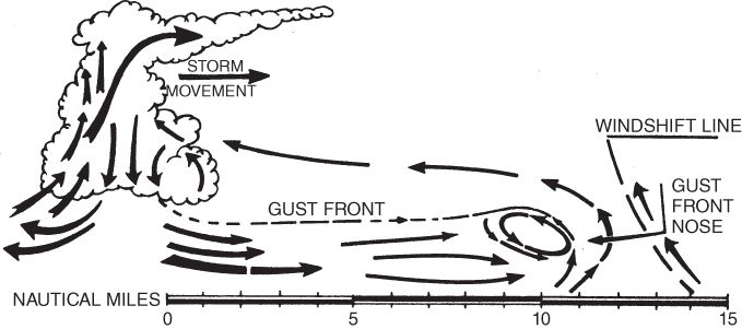
Figure 12.16 Thunderstorm gust front.
Wind shear may also be present in certain types of cold and warm fronts. Turbulence may or may not exist in wind‐shear conditions. Most fronts have shallow wind gradients; thus, the changes in wind direction and velocity are gradual. Other fronts have steep wind gradients and severe amounts of wind shear. A rule of thumb to determine the possibility of wind shear is this: If a temperature differential of 10°F or greater exists across the front and/or if the frontal speed is 30 knots or more, there is the possibility of significant low‐level wind shear.
A third source of low‐level wind shear is caused by temperature inversions, usually caused by warm air moving above a pocket of cool, calm air, as shown in Fig. 12.17. This type of wind shear can be found on clear nights, when the ground is dry and smooth. Wide temperature variations during the day and night period help create this situation. The horizontal winds in the boundary layer above ground level have been found to be as much as 70 knots, while the surface winds remained calm.
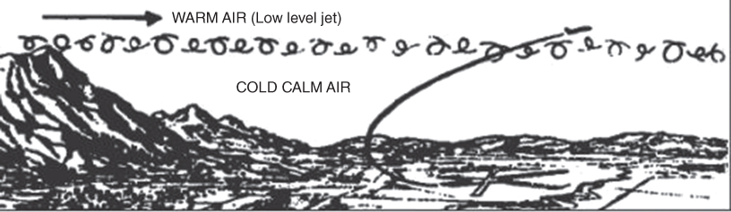
Figure 12.17 Temperature inversion LLWS.
Federal Aviation Administration, Wind Shear, P‐8740‐40
Little or no turbulence, or vertical wind velocity, is usually found at the boundary of the warm and cold air. When an aircraft is flying at a constant altitude, no significant wind shear will occur. Large variations in headwind, tailwind, and crosswind components, however, can be experienced when climbing or descending through this area.
AIRCRAFT PERFORMANCE IN LOW‐LEVEL WIND SHEAR
During Takeoff and Departure
The most hazardous condition caused by a wind shear during takeoff is when an increasing tailwind is encountered shortly after takeoff, as shown in Fig. 12.18. The sequence of events is as follows:
- Takeoff appears normal.
- Tailwind wind shear encountered just after liftoff.
- Airspeed decreases, resulting in pitch down moment.
- Airplane crashes.
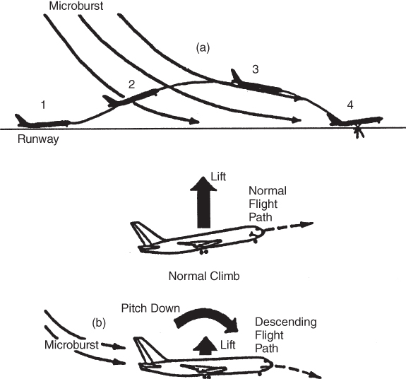
Figure 12.18 Tailwind wind shear encountered on takeoff: (a) flight path, (b) forces and moments.
During Approach to a Landing
Wind shear encountered during final approach can lead to dangerous situations. The two most likely conditions are discussed here.
- If an aircraft passes through a front where a wind shift from a headwind to either a tailwind or a reduced headwind occurs, then the shearing situation illustrated in Fig. 12.19 may exist. The sequence of events is
- Normal approach.
- Increasing downdraft and tailwind encountered.
- Airspeed decreases and pitch down results.
- Aircraft crashes short of runway.
- When an aircraft makes an approach in a tailwind condition that changes to a headwind or calm condition, the reverse situation occurs. When the wind shear is encountered, the IAS increases, the aircraft pitches up, and it climbs above the glide slope. If no thrust correction is made the aircraft climbs above the flight path and a high and fast approach results with the possibility of overshooting the runway. If the pilot reduces thrust after going high on the glide slope, then thrust must be reestablished as the aircraft returns to the glide slope or the airplane will go below the flight path and a short, hard landing will result.
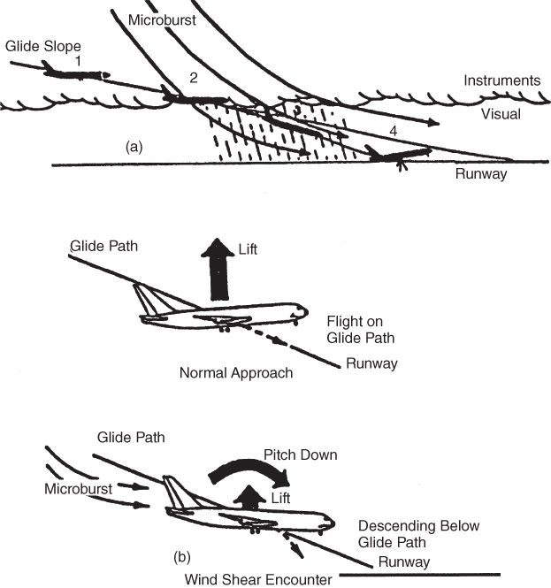
Figure 12.19 Tailwind shear encountered in landing approach: (a) flight path, (b) forces and moments.
Crosswind Burst Response
A crosswind shear burst causes the airplane to roll and/or yaw. Large crosswind shears may require large and rapid aileron inputs. Wind shears may increase the pilot workload and cause increased distraction. Horizontal vortices may also be encountered, which can cause severe roll forces and require full aileron movement to maintain aircraft control.
Turbulence Effects
Turbulence differs from wind shear in that it is sporadic. Airspeed may fluctuate in an unpredictable pattern, and in extreme conditions injury to the passengers or damage to the aircraft may occur. Moderate or greater turbulence can make changes in airspeed difficult to detect and thus delay the recognition of the presence of wind shear.
Heavy Rain
Wind shear is often accompanied by heavy rain due to the precipitation‐induced downdraft. Earlier studies of rain effects at altitude concluded that rain had a significant effect on performance, but, due to sufficient altitude, would not force the aircraft to the ground. In the approach or post takeoff flight phase, however, conditions are much more critical and the performance margin of the aircraft is considerably reduced.
Rain affects the aircraft in several ways:
- The momentum of the raindrops impact the aircraft in a downward and backward direction.
- The increased weight of the rain water film affects the gross weight of the aircraft.
- The water film is roughened by the impact of the raindrops and the aerodynamic properties of the wing are adversely affected.
- The raindrops hit the airplane unevenly, causing possible pitching or rolling moments.
Of these effects, the roughened airfoil and resulting loss of aerodynamic properties is the most important. Recent studies have indicated that as much as a 30% increase in CD and a loss of lift of more than 30% can occur due to this roughness. The AOA for CL(max) can also be reduced by 2 to 6°. At least nine major commercial aircraft accidents investigated and reported by the National Transportation Safety Board (NTSB) have involved heavy rain during takeoffs and landings.
EFFECT OF ICE AND FROST
The formation of ice or frost on the lifting surfaces of an airplane will cause deterioration of the lifting ability of the surfaces and an increase in drag. The effects of ice and frost on the lift coefficient curves are shown in Fig. 12.20. Ice is likely to accumulate near the leading edge if it is deposited during flight. This changes the contour of the airfoil and results in a considerable reduction of lift, in some cases by 25% or more. The smoothness of the skin is also reduced, and a large increase in drag results. As a result of the reduced lift and the increased drag, thrust or power required will be greater and the stall speed will increase. A third effect will be that the weight of the ice will increase the gross weight of the aircraft, complicating the effect of the reduction in lift.
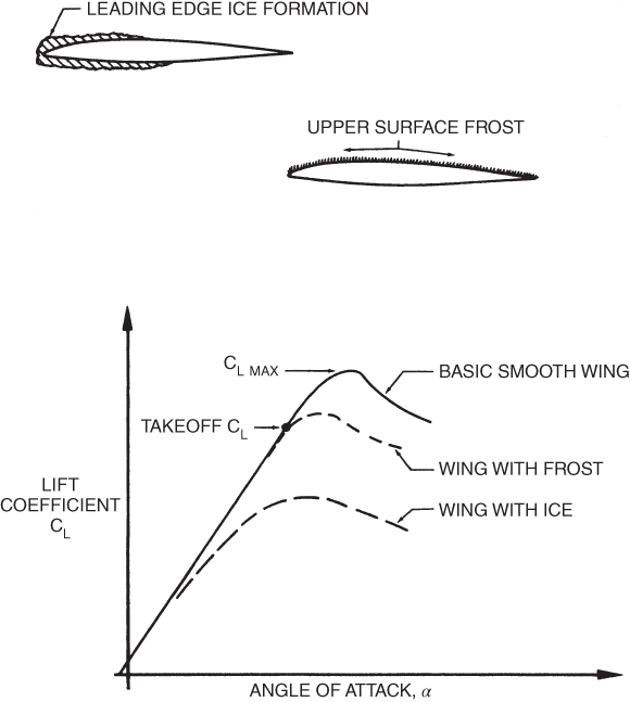
Figure 12.20 Effect of ice and frost on wings.
Obviously, all ice must be removed before flight, and any ice formed during flight must be removed using the aircraft's de‐icing equipment. If the aircraft is not equipped to handle icing conditions, or moderate or severe icing is encountered, the aircraft should climb or descend as appropriate to exit those conditions as soon as possible.
The effect of frost on the wings is not so obvious. A layer of evenly distributed frost will not appreciably change the contour of the wing but it will increase the roughness. Drag will be increased, and the kinetic energy of the air will be reduced so that stall will occur at a lower AOA and at a higher airspeed. One study showed that 0.1 in. of evenly distributed frost on the aircraft's wings will increase the stalling speed by 35%. This roughly doubles the required takeoff run.
WAKE TURBULENCE
Turbulence caused by aircraft in flight was once attributed to “propwash.” However, this phenomenon has become better understood and is now classified in two categories. Thrust stream turbulence is one of these types. It is caused by high‐velocity air from propeller blades or from jet exhausts. This type of disturbance is of primary concern during ground operations, where it can be dangerous to ground personnel and to loose gear and can cause foreign object damage (FOD) to aircraft and engines. It should not be a flight hazard except in close formation flying, or during takeoff and landing behind an aircraft that is making a ground runup.
Thrust stream turbulence dissipates fairly rapidly compared to the second category of turbulence, wake turbulence. Wake turbulence, is generated during flight and is caused by wingtip vortices. Wingtip vortices were discussed in Chapter 5, in connection with induced drag.
We will discuss wake turbulence as a hazard to other aircraft. A vortex is a highly developed rotational mass of disturbed, high‐energy air created by the wing of an aircraft as it produces lift. An aircraft creates two such rotating vortices, as shown in Fig. 12.21. As an aircraft that is producing lift passes through the air, there is a differential pressure on the bottom and the top of the wing. This causes a movement of air around the wingtips. The air rolls into two distinct vortices, one at each wingtip. The rotating process is normally complete in about 2 to 4 times the wingspan (200 to 600 ft) behind the aircraft. Vortices are also developed by helicopters and trail along behind the aircraft in the same manner as those of fixed‐wing aircraft (Fig. 12.22). This rotational energy is directly related to the weight, lift being generated, and wingspan of the aircraft. It is inversely related to the airspeed and, therefore, the vortices are a maximum during takeoff and landing at high gross weights.
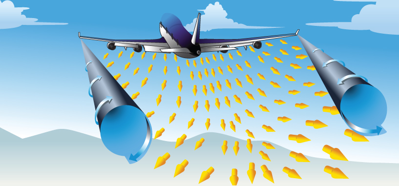
Figure 12.21 Wingtip vortices behind an aircraft.
U.S. Department of Transportation Federal Aviation Administration, Pilot's Handbook of Aeronautical Knowledge, 2008
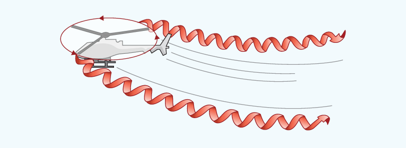
Figure 12.22 Helicopter vortices.
U.S. Department of Transportation Federal Aviation Administration, Advisory Circular, No. 90‐23G
The force of the air in wingtip trailing vortices can easily exceed the aileron control capacity or climb rate of light aircraft. These forces can cause some light aircraft to roll completely over and to be forced into the ground. A typical mishap is the case where, just before touchdown, a wing drops and contact is made with the runway while the aircraft is in a wing‐down attitude. Another possible result, at altitude, is the inadvertent entry into an unusual attitude and resultant spin.
Current avoidance of wake turbulence problems during takeoffs and landings is accomplished by requiring time intervals between aircraft depending on size, usually between 2 and 4 minutes. In the takeoff pattern the following aircraft should become airborne before the lead aircraft and should climb above the turbulence. In the landing pattern the following aircraft should touch down past the point where the lead aircraft has touched down (Fig. 12.23).
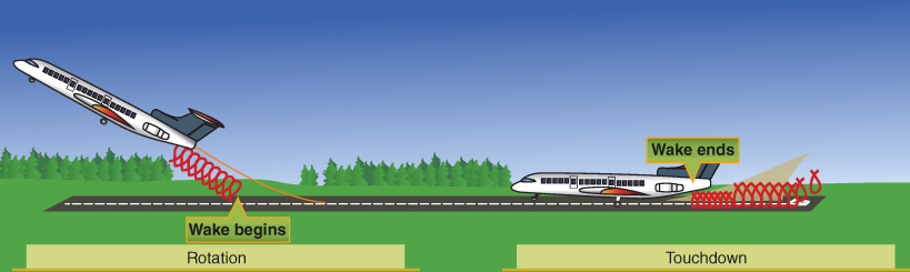
Figure 12.23 Wake turbulence avoidance.
U.S. Department of Transportation Federal Aviation Administration, Pilot's Handbook of Aeronautical Knowledge, 2008
Lateral movement of tip vortices due to crosswinds can present a hazard to takeoffs and landings when aircraft are operating from fields with parallel runways that are less than 2500 ft apart. This is illustrated in Fig. 12.24. The no‐wind movement of the vortices is away from the centerline of the airplane at about 5 knots, as shown in Fig. 12.24a. If a 5‐knot crosswind from the right is present, the left vortex will move to the left at a speed of 10 knots (Fig. 12.24b) and will present a hazard to aircraft operating on a parallel runway to the left.
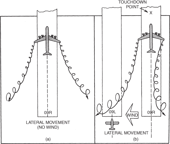
Figure 12.24 Lateral movement of tip vortices with (a) no wind and (b) crosswind.
Understanding when wake turbulence occurs, what aircraft are more likely to produce the greatest strength vortices (heavy, clean, slow), and the regulations set forth to avoid wake turbulence are all keys to improve the safety record. An aircraft producing lift will produce wake turbulence.
PROBLEMS
- The main difference between the
 curves for straight‐wing aircraft is that
- the swept‐wing aircraft has a lower value of
 .
. - the straight‐wing aircraft does not fly at as high an AOA for
 .
. - the swept‐wing aircraft does not have an abrupt loss of lift at
 .
. - All of the above
- the swept‐wing aircraft has a lower value of
- Low‐speed stall will start at the wing's trailing edge
- where C1/CL is a minimum.
- where C1/CL is a maximum.
- at the root for a swept wing.
- at the wingtip for a straight rectangular wing.
- The region of reversed command for a jet aircraft is also correctly known as
- the backside of the thrust required curve.
- the backside of the power curve.
- the backside of the drag curve.
- Both (a) and (c) above
- An aircraft should never be flown in the region of reversed command.
- True
- False
- Pulling back on the control stick (or yoke) will cause the airplane to climb if the plane is flying at
- low speed.
- high speed.
- any speed.
- A better way to climb, which will work at any speed, is to control the airspeed with the stick and add throttle to climb.
- True
- False
- An airplane is making a final approach for a landing and encounters a horizontal wind shear. Which of the types of bursts below is the most dangerous?
- Headwind burst
- Crosswind burst
- Tailwind burst
- An airplane in flight encounters wing icing. The greatest danger is that
- weight is increased.
- CD is increased.
- CL is decreased.
- Wake turbulence can cause an airplane to be turned completely upside down. To escape wake turbulence a pilot should avoid
- flying behind and below a large airplane.
- taking off or landing behind a large airplane.
- taking off or landing on a parallel runway that is downwind from one being used by large airplanes.
- All of the above
- Spin recovery consists of
- stopping spin rotation with rudder.
- lowering AOA with forward stick.
- applying ailerons into the spin direction (swept‐wing airplanes).
- All of the above
- A 10,000‐lb airplane has the Tr curve shown in Fig. 12.8. The Ta is 3000 lb and it is the same for all airspeeds. The airplane is flying at 210 knots and the pilot decides to climb and pulls back on the stick, thus reducing the speed to 200 knots. Find the ROC.
- Consider the same situation as in Problem 11, except the airspeed at the start of the maneuver is 135 knots and after the pilot pulls back on the stick, the speed is 130 knots. Find the ROC.