3
Horizontal Spans
HORIZONTAL SPANS
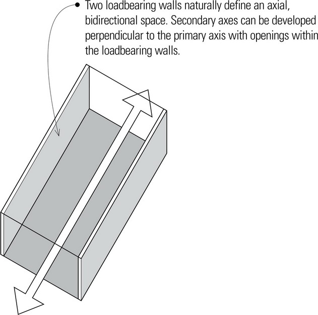
The vertical supports of a building—its columns and loadbearing walls—punctuate space and establish a measurable rhythm and scale that make the spatial dimensions comprehensible. Architectural spaces, however, also require horizontal spans to establish the floor structure that supports our weight, activities, and furnishings, and the overhead roof plane that shelters space and limits its vertical dimension.
Beams
All floor and roof structures consist of linear and planar elements, such as joists, beams, and slabs, designed to carry and transfer transverse loads across space to supporting elements. To understand the structural behavior of these spanning elements, we begin with a general discussion of beams, which applies as well to joists, girders, and trusses.
HORIZONTAL SPANNING SYSTEMS
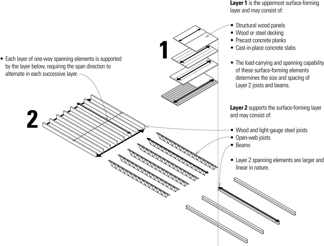
Horizontal spans may be traversed by nearly homogeneous slabs of reinforced concrete or by hierarchical layers of steel or wood girders, beams, and joists supporting a plane of structural sheathing or decking.
Concrete
- Cast-in-place concrete floor slabs are classified according to their span and cast form.
- Precast concrete planks may be supported by beams or loadbearing walls.
Steel
- Steel beams support steel decking or precast concrete planks.
- Beams may be supported by girders, columns, or loadbearing walls.
- Beam framing is typically an integral part of a steel skeleton frame system.
- Closely spaced light-gauge or open-web joists may be supported by beams or loadbearing walls.
- Steel decking or wood planks have relatively short spans.
- Joists have limited overhang potential.
Wood
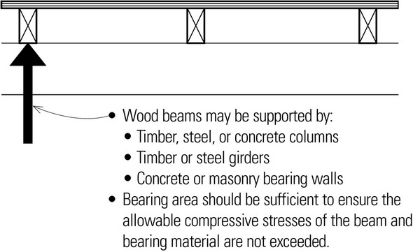
- Wood beams support structural planking or decking.
- Beams may be supported by girders, posts, or loadbearing walls.
- Concentrated loads and floor openings may require additional framing.
- Underside of floor structure may be left exposed; an applied ceiling is optional.
- Relatively small, closely spaced joists may be supported by beams or loadbearing walls.
- Subflooring, underlayment, and applied ceiling finishes have relatively short spans.
- Joist framing is flexible in shape and form.
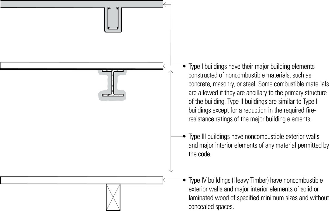
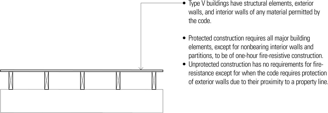
Types of Construction
The preceding page describes the major types of reinforced concrete, steel, and wood spanning systems. The material requirements for spanning structures are generally determined by the magnitude of the loads and the lengths of the spans. Another important consideration in selecting a structural material is the type of construction required by the building code for the size and occupancy of the building. Building codes classify the construction of a building according to the fire resistance of its major elements: structural frame, exterior and interior bearing walls, nonbearing walls and partitions, and floor and roof assemblies.
Concrete
- Noncombustible
- Types I, II, or III construction
Steel
- Noncombustible
- The application of fire-resistive materials can increase the durability of even noncombustible materials in a fire. Even steel or concrete, if unprotected, can lose strength under fire exposure.
- Types I, II, and III construction
Wood
- Combustible
- Wood can be made more fire-resistant by applying fire-retardant coverings to impede the spread of fire and extend the durability of the building structure in a fire.
- Types IV and V construction
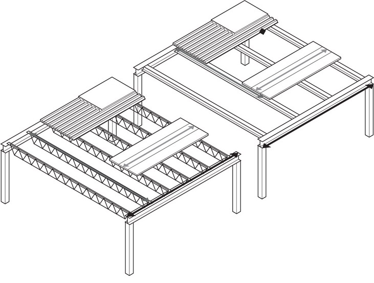
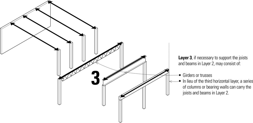
Structural Layers
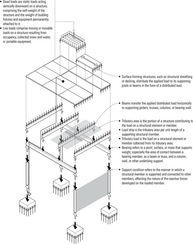
When supporting uniformly distributed loads, the first or surface-forming layer should be selected for greatest efficiency. Thus, the selection of structural members for a spanning system and the spacing between them begins at the point of application of the live load. The load is gathered through successive layers of structure until it is resolved at the foundation. Typically, greater spans will result in more layers to reduce the amount of material used, resulting in greater efficiency.
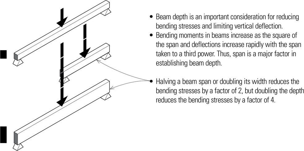
Construction Depth
The depth of a floor or roof system is directly related to the size and proportion of the structural bays it must span, the magnitude of the live loads, and the strength of the materials used. The structural depth of floor and roof systems becomes critical in areas where zoning ordinances restrict building heights and maximizing the usable floor area is important to the economic feasibility of a project. For floor systems between habitable spaces stacked one above the other, additional factors to consider are the blockage of both airborne and structure-borne sound and the fire-resistance rating of the assembly.
The following points can be applied to both steel and timber spanning systems.
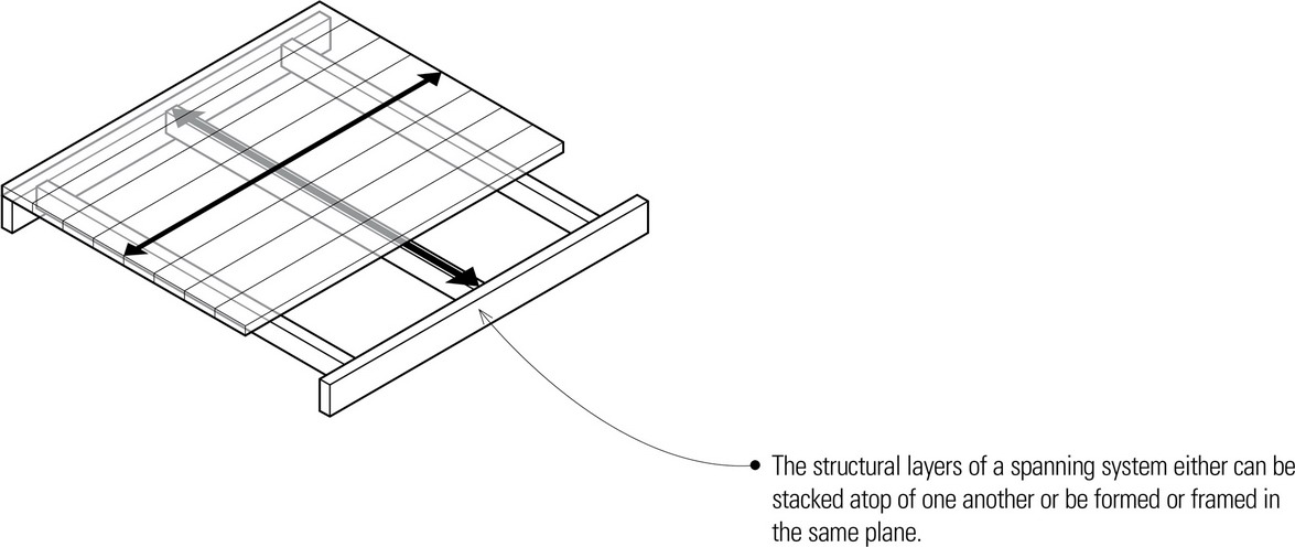
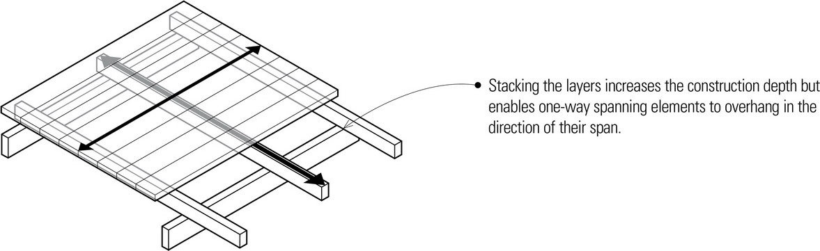
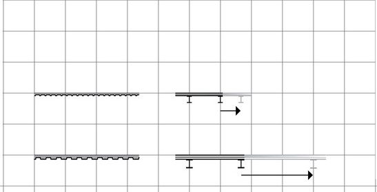
- Stacking one layer atop the supporting layer below provides space for other systems to cross over the supporting layer between members of the supported layer.
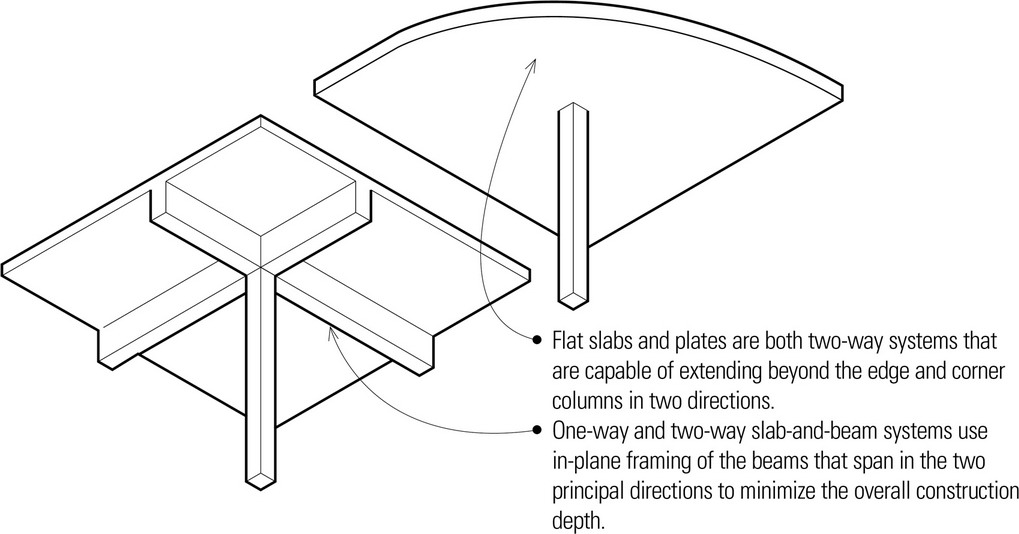
- The layers may be formed or framed in plane to minimize the construction depth. In this case, the depth of the largest spanning elements, such as girders or trusses, establishes the overall depth of the system.
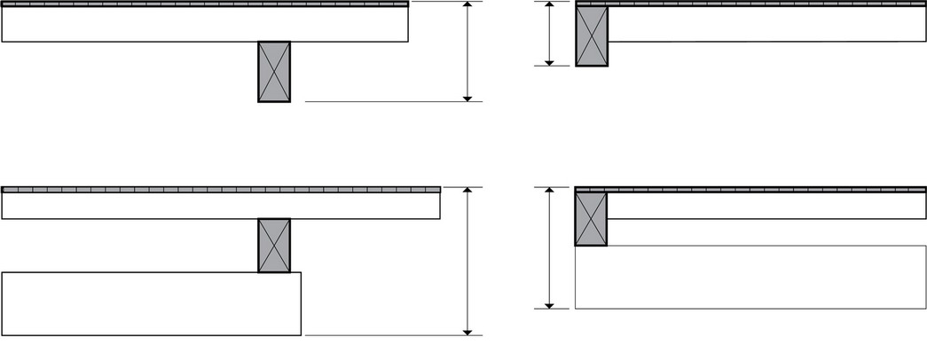
- In some cases, the overall depth of a spanning structure can be reduced further by integrating the mechanical and structural systems so that they occupy the same volume rather than exist in separate layers. This, however, requires careful study since this may require penetrating structural members, which can cause localized stresses.
The sizing and proportioning of structural elements and assemblies requires an understanding of the context in which each element or assembly is used—the type of loads being carried and what is supporting the element or assembly.
Distributed and Concentrated Loading
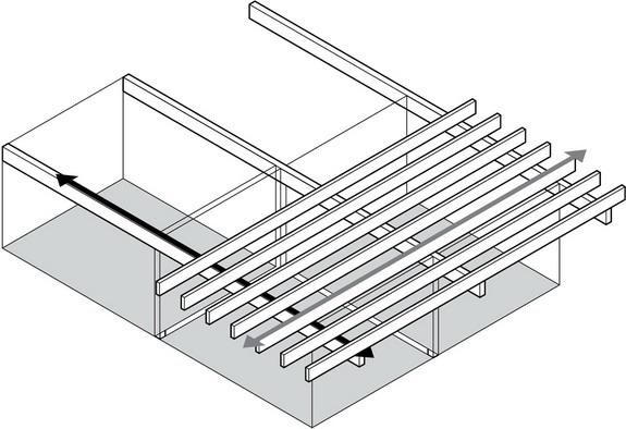
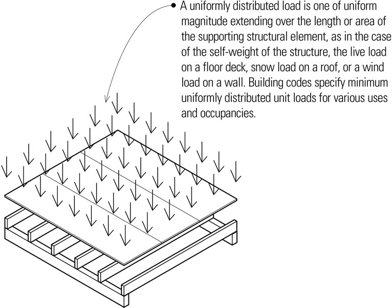
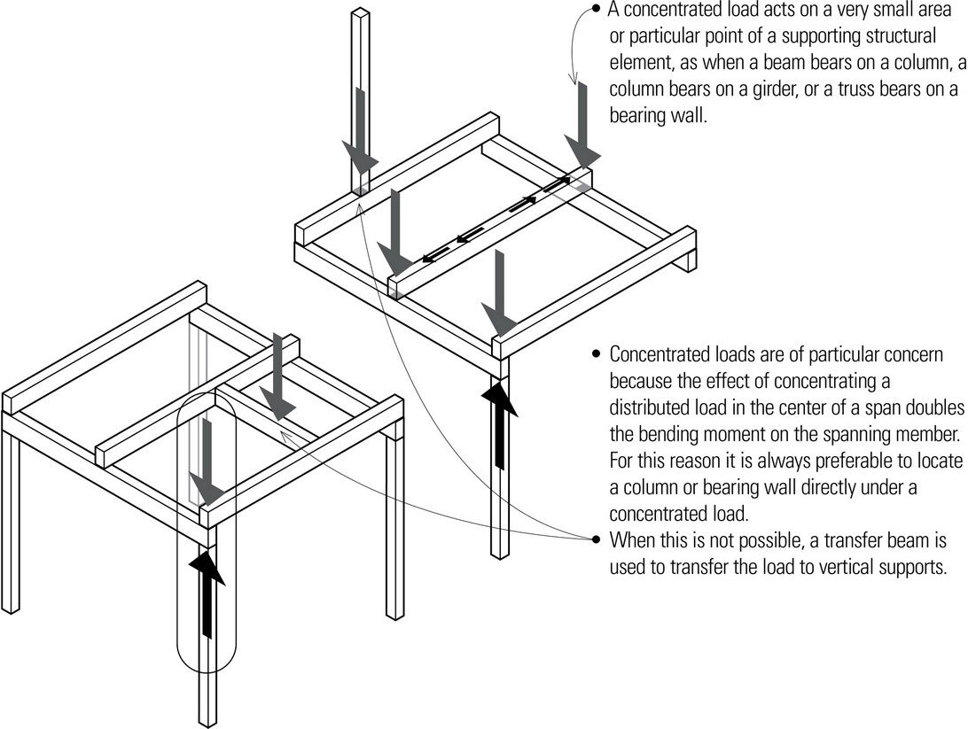
Building structures are designed to withstand a combination of dead loads, live loads, and lateral loads. Just as important as the magnitude of these loads is the manner in which the loads are applied to a spanning structure. Loads may be applied either in a distributed or a concentrated manner. Understanding this distinction is important because some structural systems are better suited for carrying relatively light, uniformly distributed loads while others are more appropriate for supporting a set of concentrated loads.
Many floor and roof structures are subject to relatively light, distributed loading. In these cases, when stiffness and resistance to deflection tend to govern the design of the structure, it is usually appropriate to select a distributed type of structure using a number of relatively smaller, more closely spaced spanning elements, such as joists. Distributed structural systems, however, are not well suited to carrying concentrated loads, which require fewer and larger one-way spanning elements such as girders and trusses for their support.
- Because it must safely support moving loads, a floor system should be relatively stiff while maintaining its elasticity. Due to the detrimental effects that excessive deflection and vibration would have on finish flooring and ceiling materials, as well as on human comfort, deflection rather than bending often becomes the critical controlling factor in the design of floor systems.
Load Tracing
Load tracing is the process of modeling how a structure collects, channels, and redirects the loads resulting from external forces through the hierarchy of its members to the foundation and underlying soil. The analysis usually starts at the roof level with the smallest members actually picking up the loading, and proceeds by tracing the loads through each collecting member. The reactions of each member to its loading become forces on the supporting members in the next layer.
- The hierarchical sequence of load tracing is generally the same for concrete, steel, and timber spanning systems.
- Anchorage refers to the means for binding a structural member to another or to its foundation, often to resist uplifting and horizontal forces.
- Rigid floor planes can also be designed to serve as horizontal diaphragms which act as thin, wide beams in transferring lateral forces to shear walls. See Chapter 5 for a more detailed discussion of the various methods for providing lateral stability.
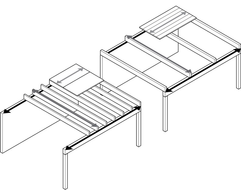
The dimensions and proportions of the bays defined by a structural grid influence—and may often limit—the material and structural choices of the horizontal spanning systems.
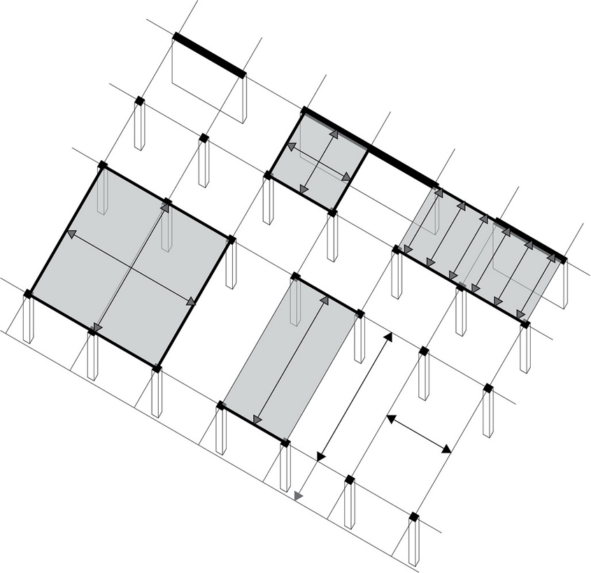
- The orientation and length of overhangs and size and location of openings within the floor plane should be considered in the layout of the structural supports for the floor. The edge conditions of the floor structure and its connection to supporting foundation and wall systems affect both the structural integrity of a building and its physical appearance.
Material
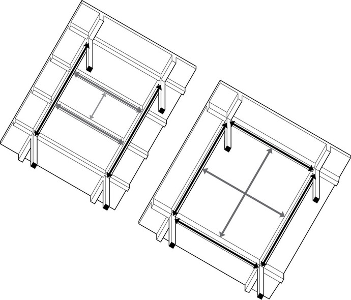
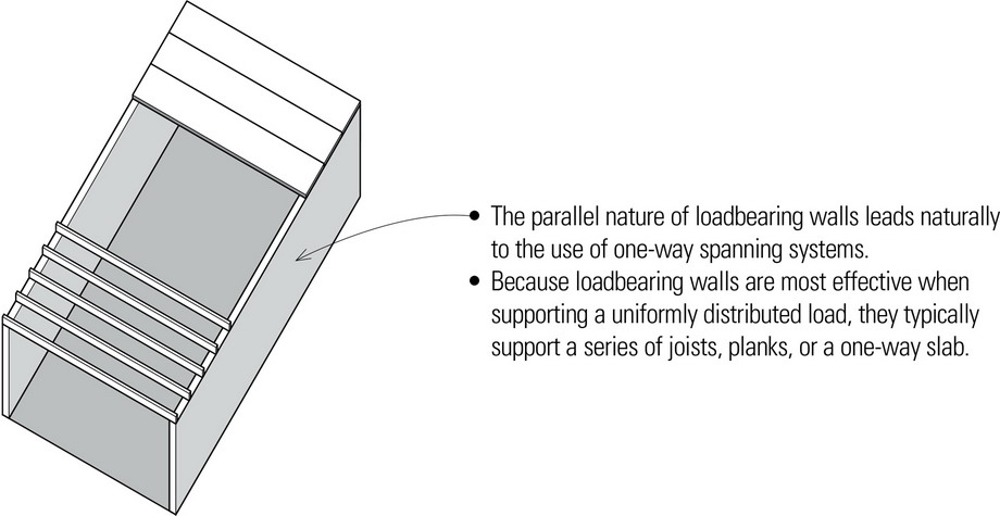
- Both wood and steel spanning elements lend themselves to one-way systems, while concrete is appropriate for both one-way and two-way spanning systems.
Bay Proportion
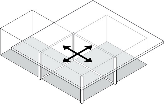
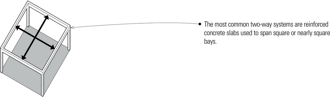
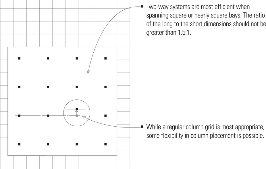
- Two-way systems are best used to span square or nearly square bays.
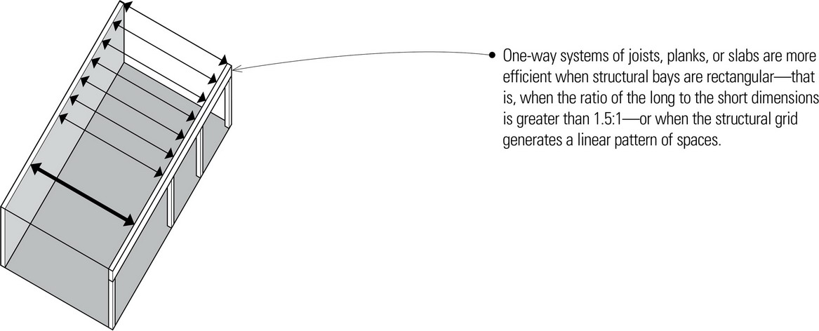
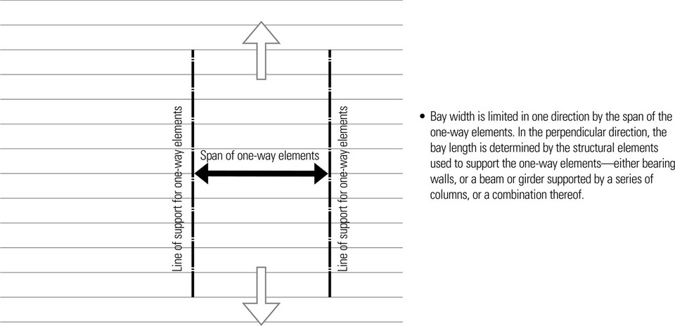
- While two-way spanning systems require square or nearly square bays, the converse is not necessarily true. One-way systems are flexible and can span in either direction of either square or rectangular structural bays.
Span Direction
- The direction of horizontal spans, as determined by the location and orientation of the vertical supporting planes, affects the nature of the spatial composition, the qualities of the spaces defined, and to some extent, the economics of construction.
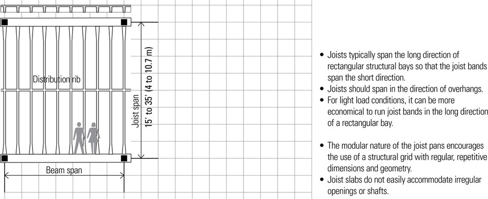
- One-way joists and beams can span in either the short or long direction of rectangular bays, with their supporting beams, columns, or bearing walls spanning in an alternate, usually perpendicular direction.
Span Length
- The spacing of supporting columns and bearing walls determines the length of horizontal spans.
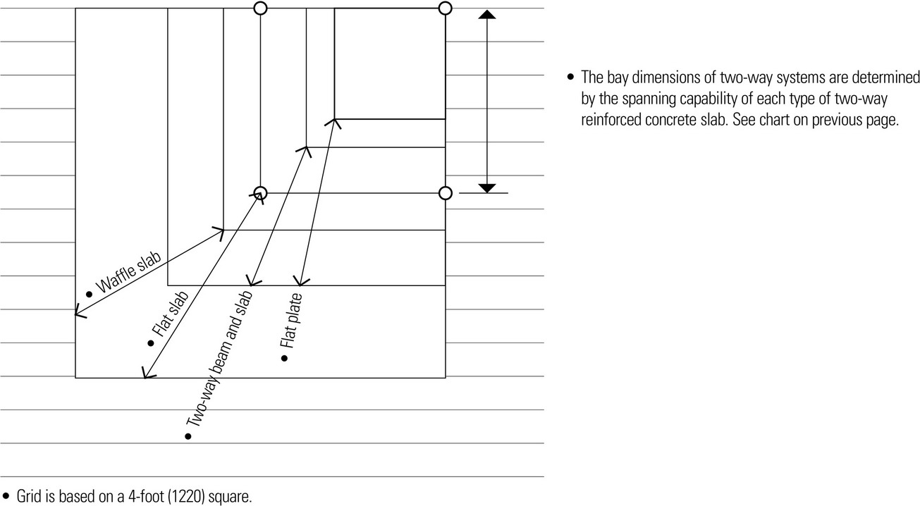
- Certain materials have an appropriate range of bay spans. For example, the various types of cast-in-place concrete slabs have bay spans in the range from 6 to 38 feet (1.8 to 12 m). Steel is a more flexible material because its spanning elements are manufactured in different forms, from beams to open-web joists and trusses, which can span from 15 to 80 feet (5 to 24 m).
ONE-WAY SYSTEMS
Listed below are appropriate ranges for basic types of spanning elements.
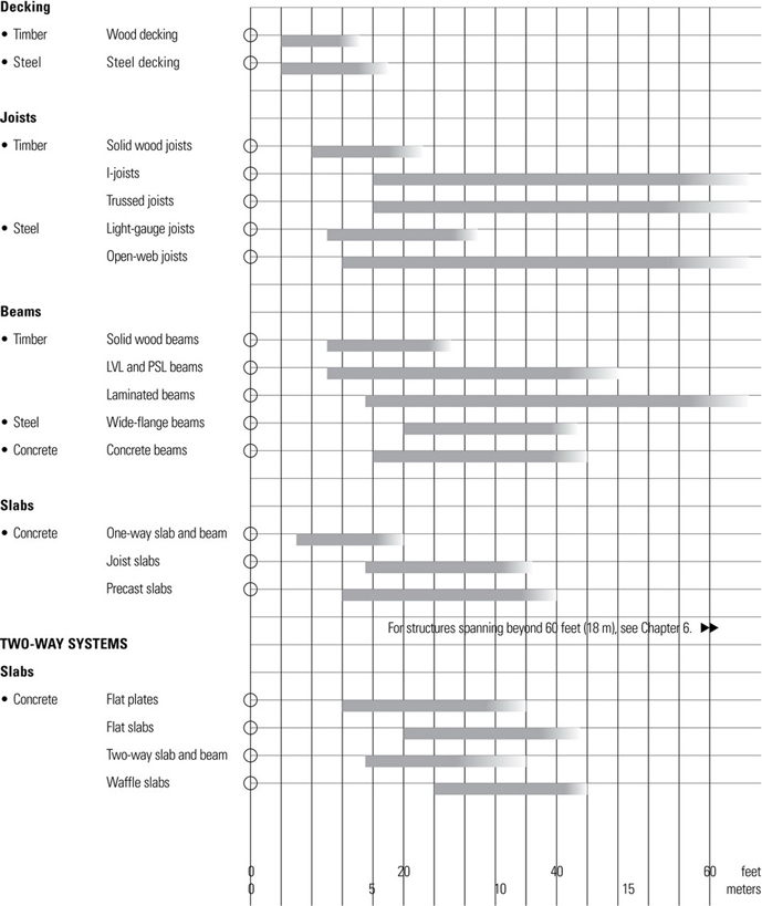
CONCRETE SPANNING SYSTEMS
Concrete Slabs
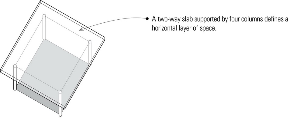
Concrete slabs are plate structures that are reinforced to span either one or both directions of a structural bay. They are classified according to their method of spanning and the form in which they are cast. Because of their noncombustibility, concrete slabs can be used in all types of construction.
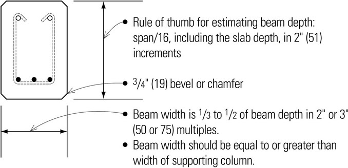
Concrete Beams
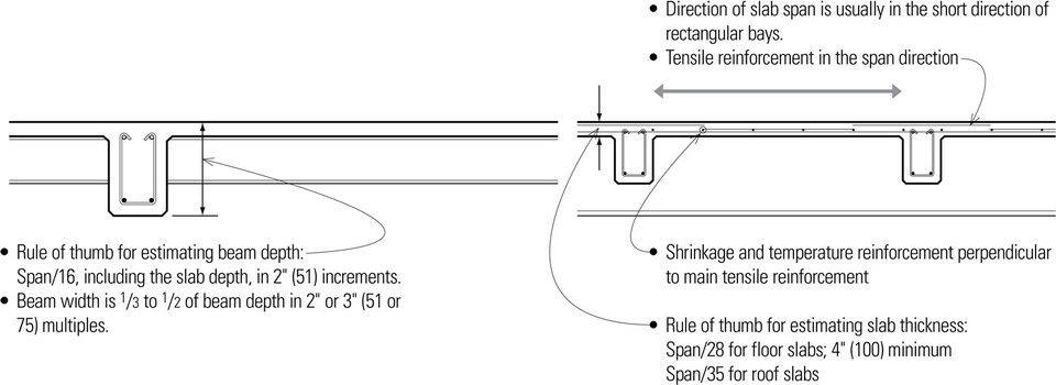
Reinforced concrete beams are designed to act together with longitudinal and web reinforcement in resisting applied forces. Cast-in-place concrete beams are almost always formed and placed along with the slab they support. Because a portion of the slab acts as an integral part of the beam, the depth of the beam is measured to the top of the slab.
One-Way Slabs
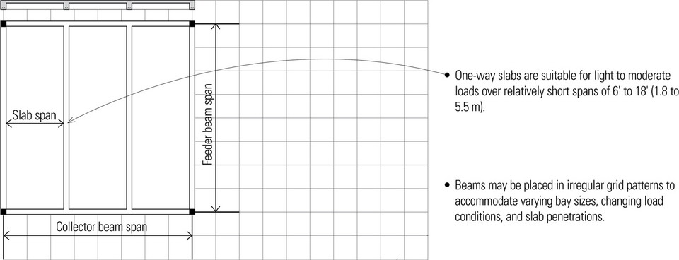
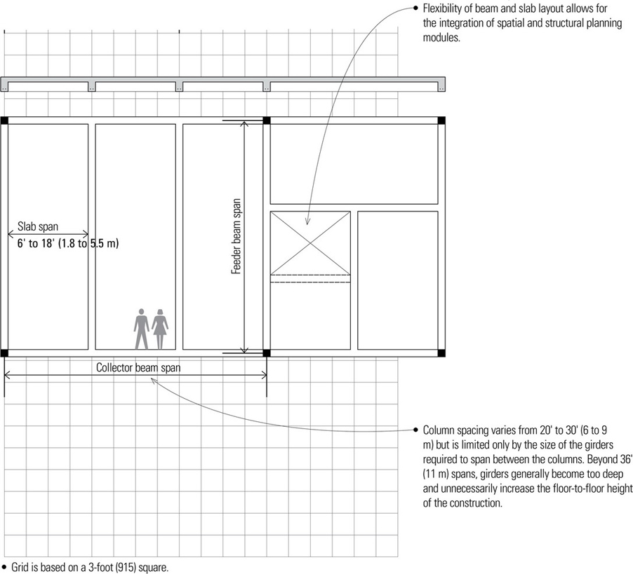
One-way slabs are uniformly thick and structurally reinforced to span in one direction between supports. They are suitable for light to moderate load conditions over relatively short spans of 6 to 18 feet (1.8 to 5.5 m).
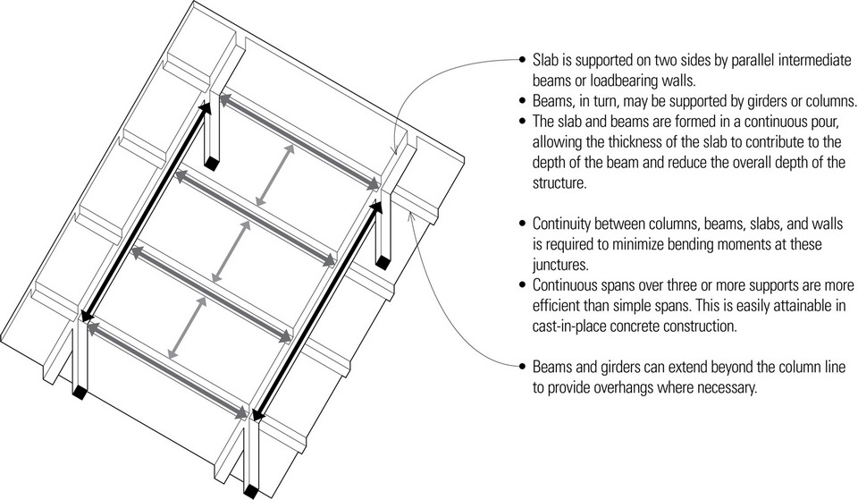
While one-way slabs can be supported by concrete- or masonry-bearing walls, they are more typically cast integrally with parallel supporting beams, which in turn are supported by girders or bearing walls. These beams allow for greater bay sizes and flexibility of layout.
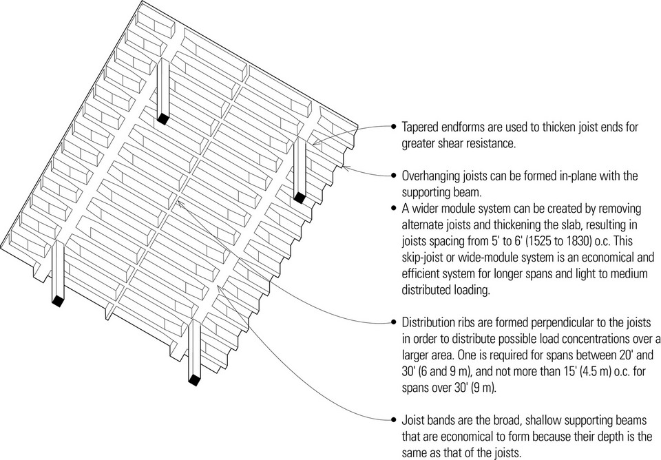
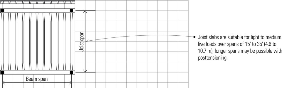
Joist Slabs
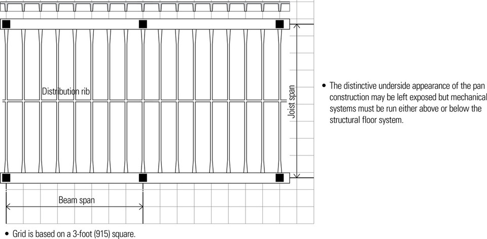
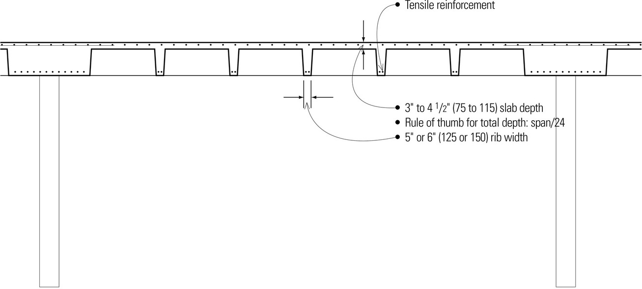
Joist slabs are cast integrally with a series of closely spaced joists, which in turn are supported by a parallel set of beams. Designed as a series of T-beams, joist slabs are more suitable for longer spans and heavier loads than one-way slabs.
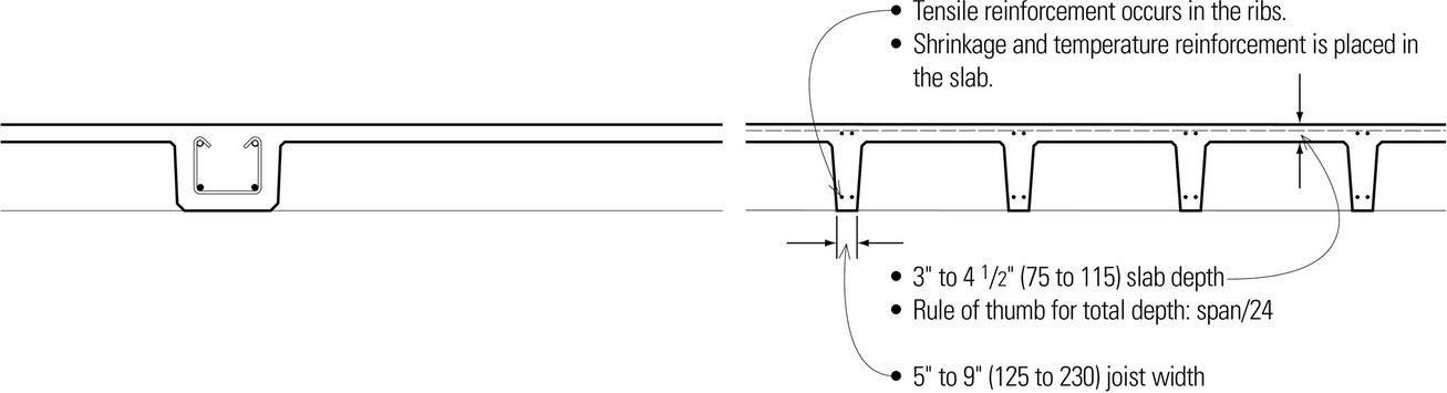
- The pan joist system provides the necessary depth and stiffness while reducing the self-weight of the slab construction.
- The pans used to form the joists are reusable metal or fiberglass molds, available in 20″ and 30″ (510 and 760) widths and from 6″ to 20″ (150 to 510) depths in 2″ (51) increments. Tapered sides allow for easier removal.
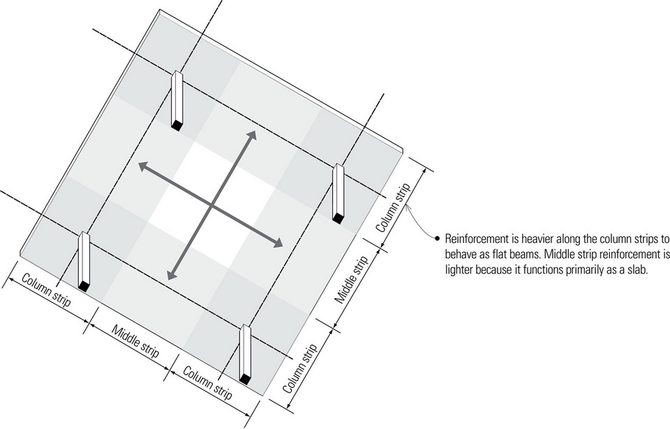
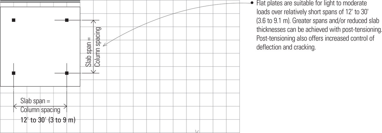
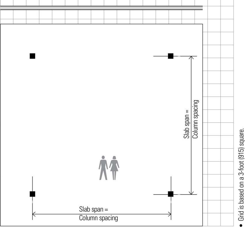
Flat Plates
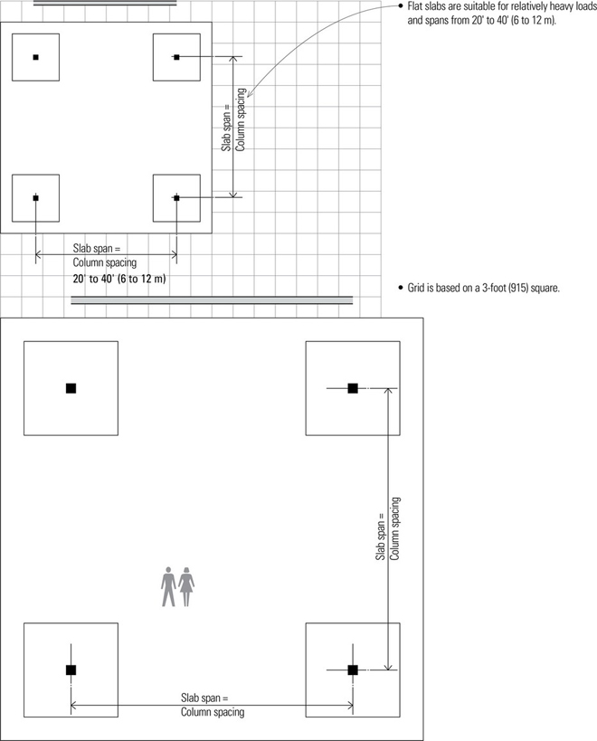
Flat plates are concrete slabs of uniform thickness reinforced in two or more directions and supported directly by columns without beams or girders. Simplicity of forming, lower floor-to-floor heights, and some flexibility in column placement make flat plates practical for apartment and hotel construction.
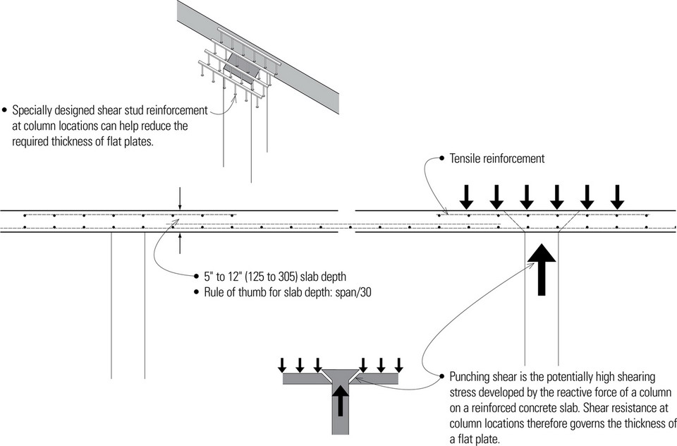
- The shallow depth of the slab-column junction limits the moment that can be transmitted through the joint and reduces its lateral resistance. The junction also restricts the minimum column size that may be used. For preliminary design, use a minimum square column dimension that is twice the thickness of the slab it supports.
- The omission of beams and joists offers flexibility in the layout of mechanical, plumbing, and electrical systems, but suspended ceilings are required to conceal their runs.
- For maximum efficiency, flat plates should have a continuous span of at least three bays in both directions, and successive span lengths should not differ by more than a third of the longer span.
- Individual columns may be offset by as much as 10 percent of the span from the regular column lines, but any shift should occur on all levels so that columns on successive floors remain vertically aligned.
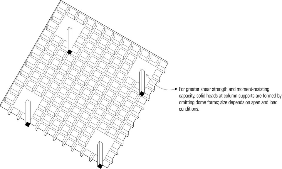
Flat Slabs
Flat slabs are flat plates thickened at their column supports to increase their shear strength and moment-resisting capacity.
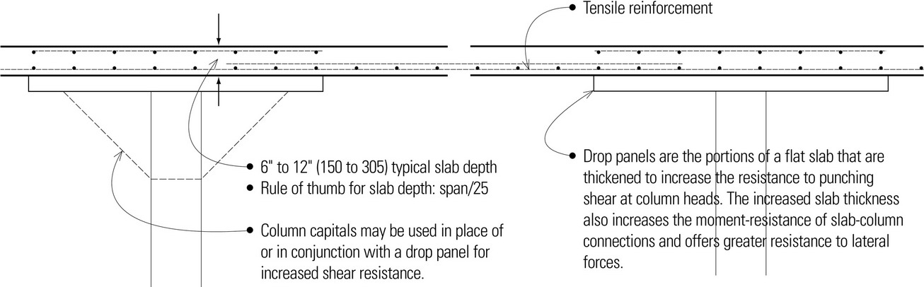
- Minimum projection of drop panel: 0.25 × slab thickness
- Minimum width of drop panel: 0.33 span
- The drop panels may result in greater overall floor depths than flat plate construction.
- The space between drop panels may be used for mechanical runs and reduce overall floor depth.

- Flat slabs offer flexibility in the layout of columns and mechanical systems.
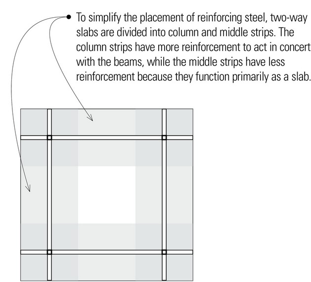
- Openings are restricted to the middle two-thirds of the slab span.
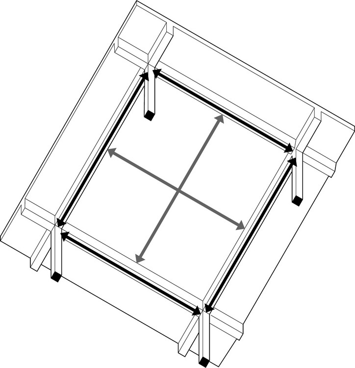
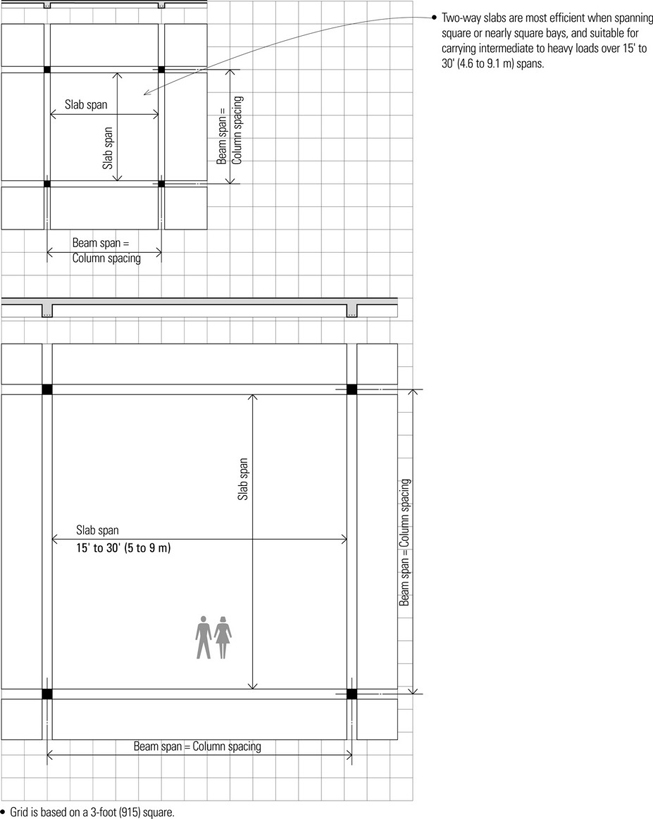
Two-Way Slabs with Beams
A two-way slab of uniform thickness may be reinforced in two directions and cast integrally with supporting beams and columns on all four sides of square or nearly square bays. Two-way slab and beam construction is effective for medium spans and heavy loads. A principal advantage of concrete slab-and-beam systems over flat slabs and plates is the rigid frame action that is made possible by the column-beam interaction for resisting lateral loads. The principal disadvantages are the increased cost of formwork and greater construction depth, particularly when mechanical ductwork must run below the beam structure.
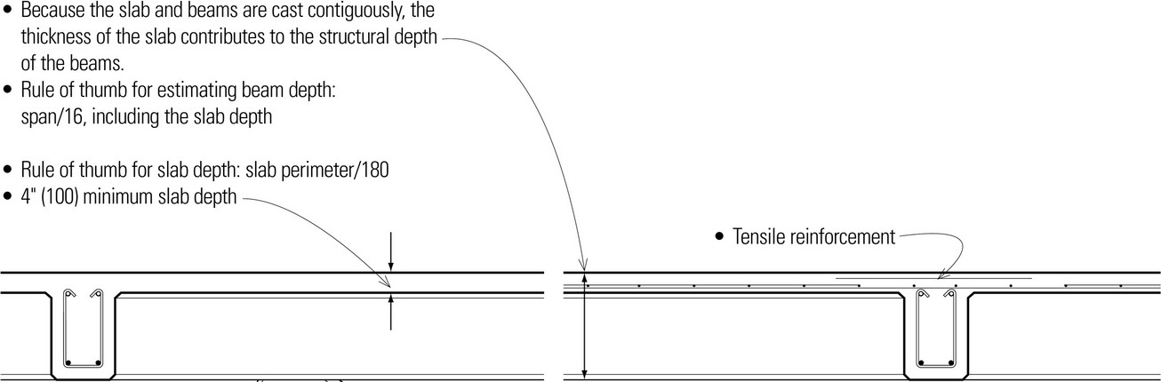
- Beam-column connections can provide moment resistance for increased lateral stability.
- Mechanical systems must run below the beams in both directions, increasing the overall depth of the floor or roof construction. Using a raised floor system and locating the mechanical systems above the structural floor can alleviate this difficulty.
Waffle Slabs
Waffle slabs are two-way concrete slabs reinforced by ribs in two directions. They are able to carry heavier loads and span longer distances than flat slabs.
- Square metal or fiberglass dome forms are available in 19″ and 30″ (485 and 760) widths and from 8″ to 20″ (205 to 510) depths in 2″ (51) increments. Tapered sides allow for easier removal.
- 19″ (485) domes and 5″ (125) ribs create a 2′ (610) module; 30″ (760) domes and 6″ (150) ribs produce a 3′ (915) module.
- Coffered underside can be architecturally desirable and is usually left exposed.
- When the underside of a waffle slab is left exposed, it is necessary to expose the mechanical, electrical, and plumbing systems or run them in a raised floor system above the structural floor.
- The location of ceiling fixtures, such as luminaires and fire sprinklers, require careful integration with the coffers.
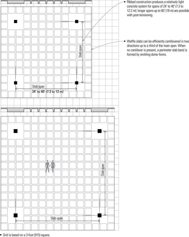
- For maximum efficiency, bays should be square or nearly as square as possible.
- The modular nature of the dome system encourages the use of a structural grid with regular, repetitive dimensions and geometry.
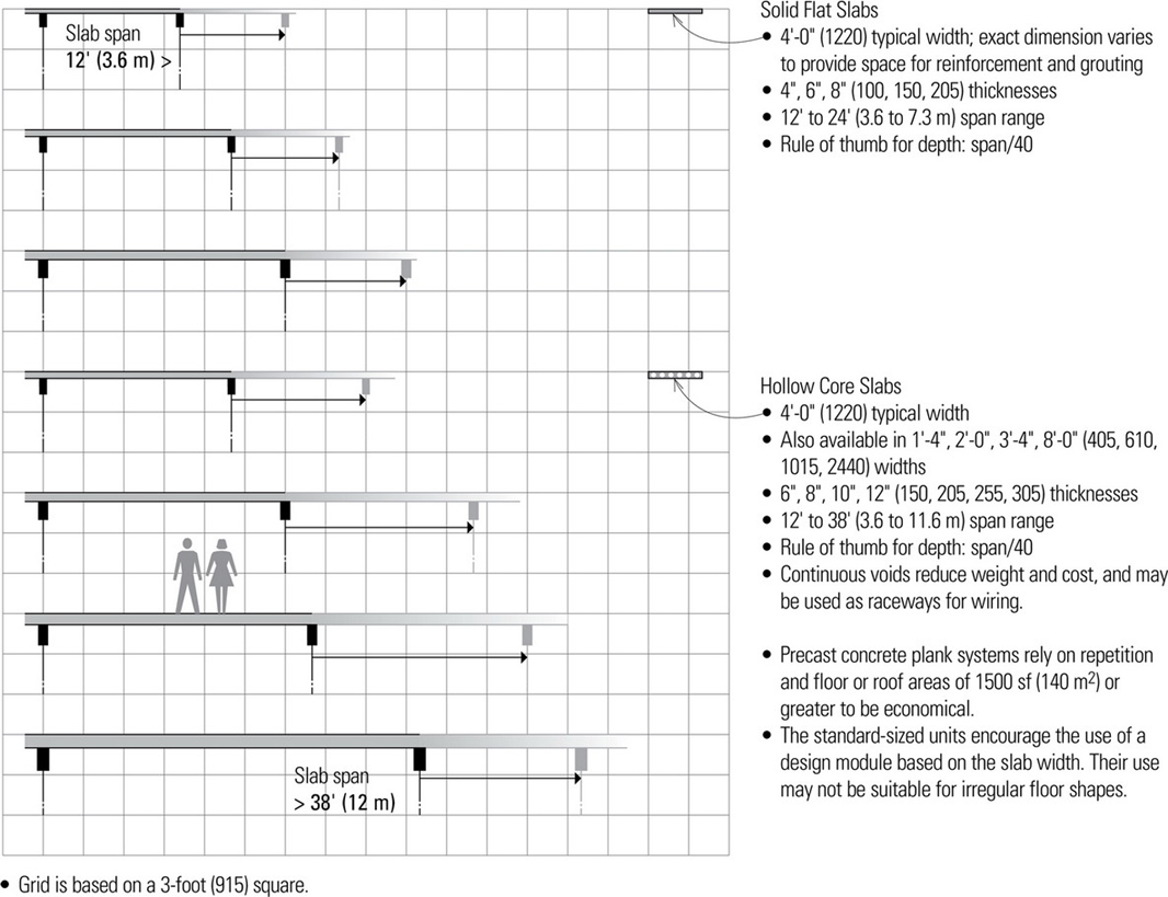
Precast Concrete Slabs
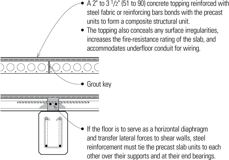
Precast concrete slabs are one-way spanning units that may be supported by site-cast concrete, precast concrete, or masonry bearing walls, or by steel, site-cast concrete, or precast concrete frames. The precast units are manufactured with normal-density or structural lightweight concrete and prestressed for greater structural efficiency, which results in less depth, reduced weight, and longer spans.
The units are cast and steam-cured in a plant off-site, transported to the construction site, and set in place as rigid components with cranes. The size and proportion of the units may be limited by the means of transportation. Fabrication in a factory environment enables the units to have a consistent quality of strength, durability, and finish, and eliminates the need for on-site formwork.
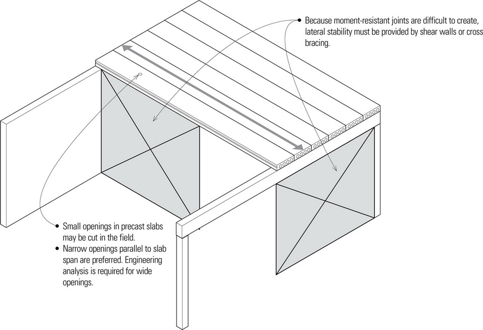
- The inherent fire resistance and quality finish allows the underside of precast slabs to be caulked, painted, and exposed as a finish ceiling; a ceiling finish may also be applied to or be suspended from the slab units.
- When the undersides of the slab units are exposed as a finished ceiling, mechanical, plumbing, and electrical are also exposed.
- Precast slabs exposed as a finish ceiling may require noise-abatement treatment.
STEEL SPANNING SYSTEMS
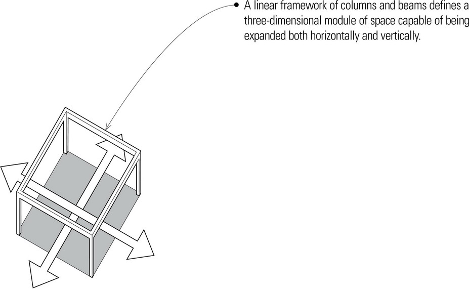
Structural Steel Framing
Structural steel girders, beams, trusses, and columns are used to construct a skeleton frame for structures ranging in size from one-story buildings to skyscrapers. Because structural steel is difficult to work on-site, it is normally cut, shaped, and drilled in a fabrication shop according to design specifications; this can result in relatively fast, precise construction of a structural frame.
Structural steel may be left exposed in unprotected noncombustible construction, but because steel can lose strength rapidly in a fire, fire-rated assemblies or coatings are required to qualify as fire-resistive construction. In exposed conditions, corrosion resistance is also required.
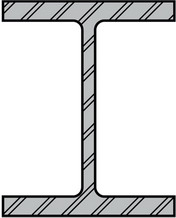
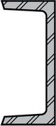
Steel Beams and Girders
- More structurally efficient wide-flange (W) shapes have largely superseded the classic I-beam (S) shapes. Beams may also be in the form of channel (C) sections, structural tubing, or composite sections.
- Connections usually use transitional elements, such as steel angles, tees, or plates. The actual connections may be riveted but are more often bolted or welded.
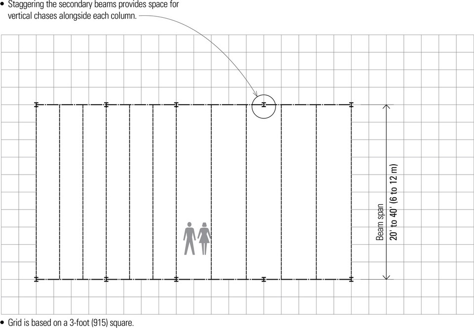
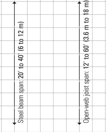
- Typical span range for steel beams is 20′ to 40′ (6 to 12 m); above 32′ (10 m), however, open-web steel joists become an economical alternative due to their reduced weight.
- Rules of thumb for estimating beam depth:
Steel beams: span/20
Steel girders: span/15 - Beam width: ⅓ to ½ of beam depth
- The general objective is to use the lightest steel section that will resist bending and shear forces within allowable limits of stress and without excessive deflection for the intended use.
- In addition to material costs, the labor costs required for erection must also be considered.
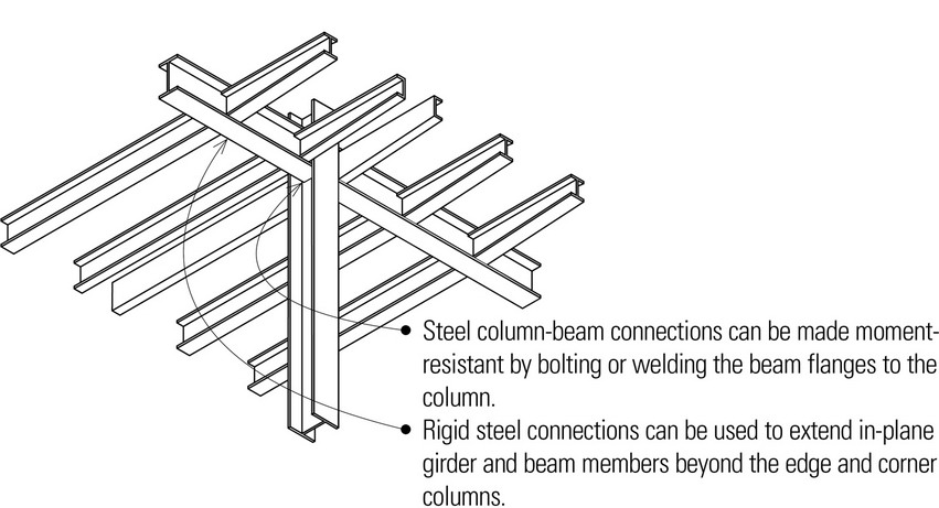
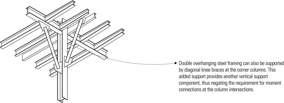
- Resistance to lateral wind or earthquake forces requires the use of shear walls, diagonal bracing, or rigid framing with moment-resisting connections.
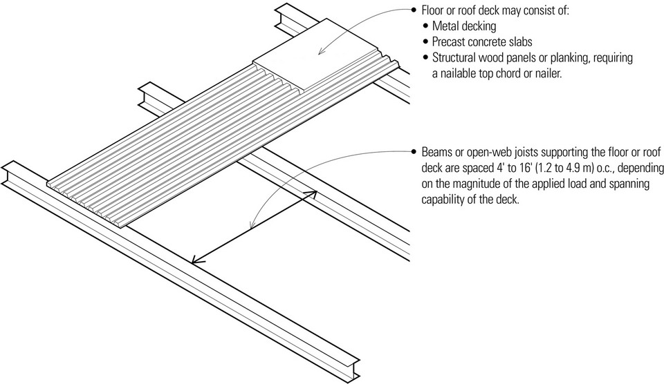
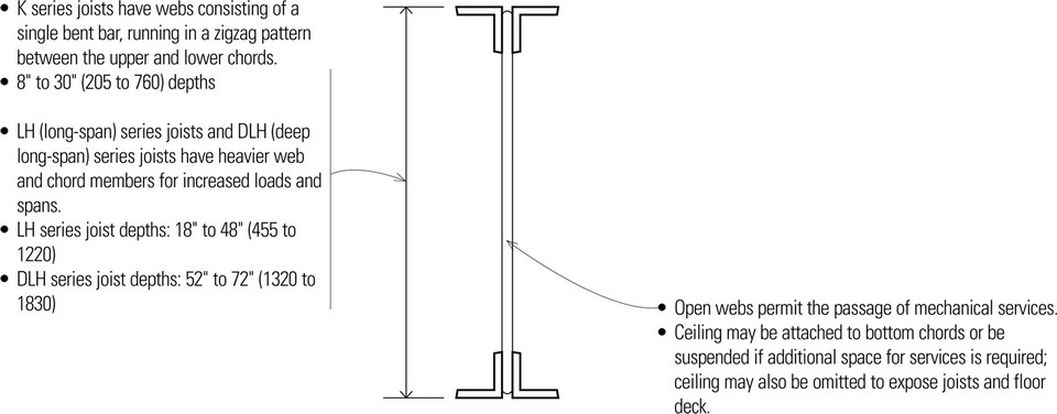
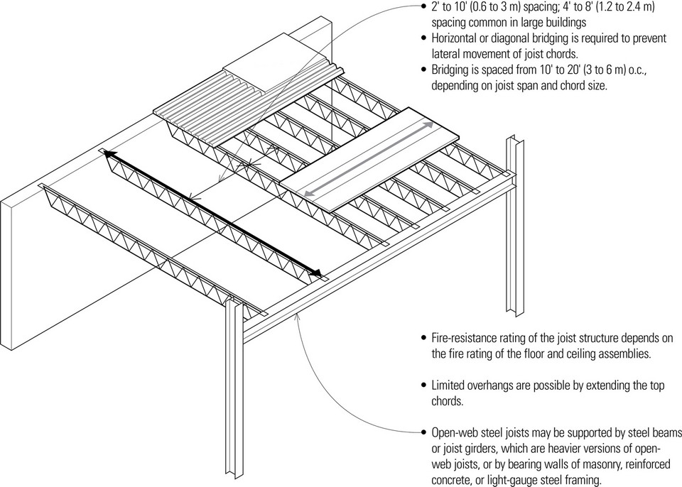
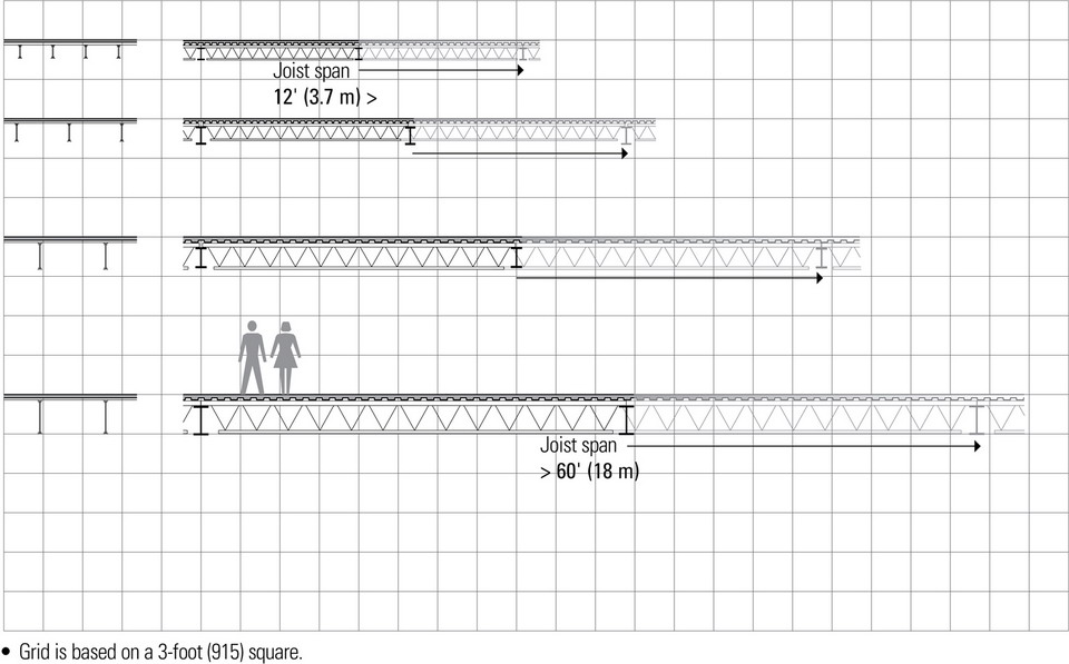
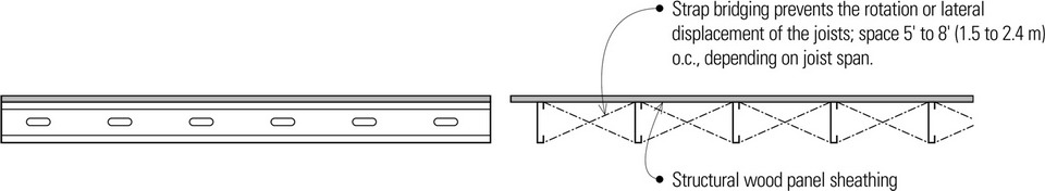
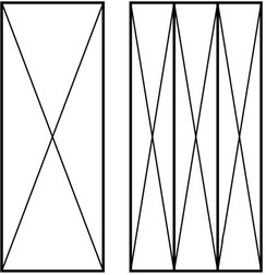
Open-Web Steel Joists
Open-web joists are lightweight, shop-fabricated steel members having a trussed web. They provide an economical alternative to steel beams for light to moderate distributed loads, especially for spans greater than 32′ (10 m).
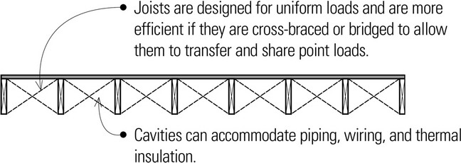
- The framing works most efficiently when the joists carry uniformly distributed loads. If properly engineered, concentrated loads may bear over the panel points of the joists.
- Span range or open-web steel joists: 12′ to 60′ (3.6 to 18 m)
- Rule of thumb for estimating open-web joist depth: span/24
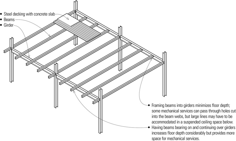
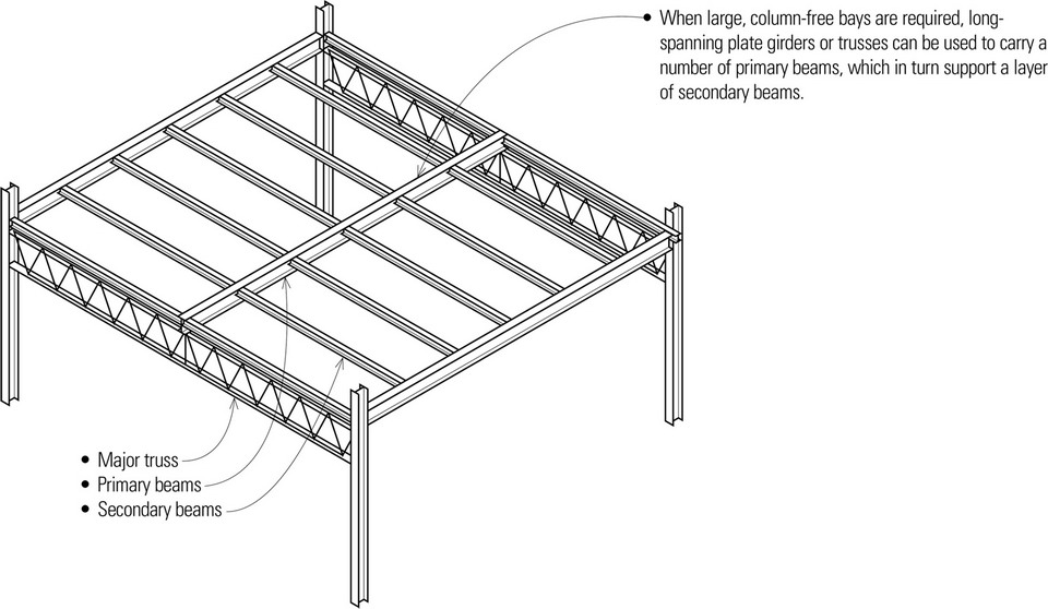
One-Way Beam System
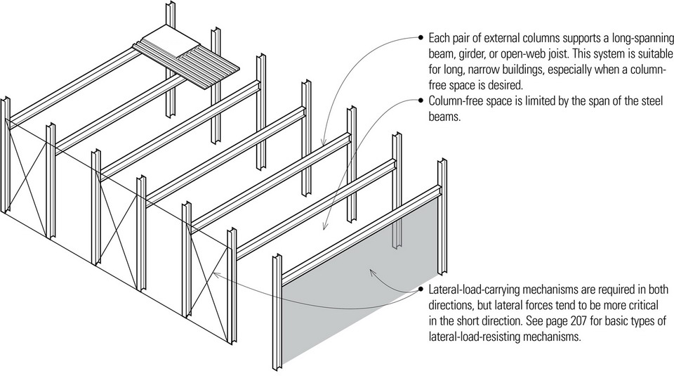

Beam-and-Girder System
- Economical spans for primary beams or girders range from 20′ to 40′ (6 to 12 m).
- Economical spans for secondary beams range from 22′ to 60′ (7 to 20 m).
- Both primary and secondary beams may consist of structural steel sections for spans up to 32′ (10 m). For greater spans, open-web joists or truss girders are more economical.
- Steel framing should use rectangular bay units, with comparatively lightly loaded secondary beams having longer spans than the more heavily loaded primary beams or girders.
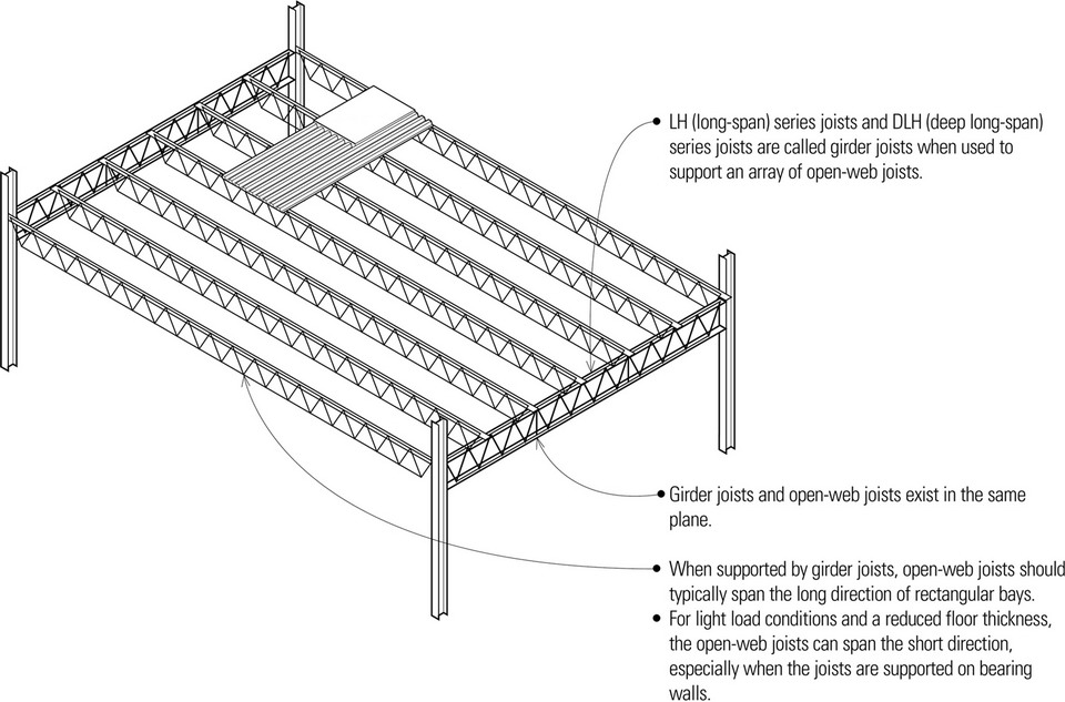
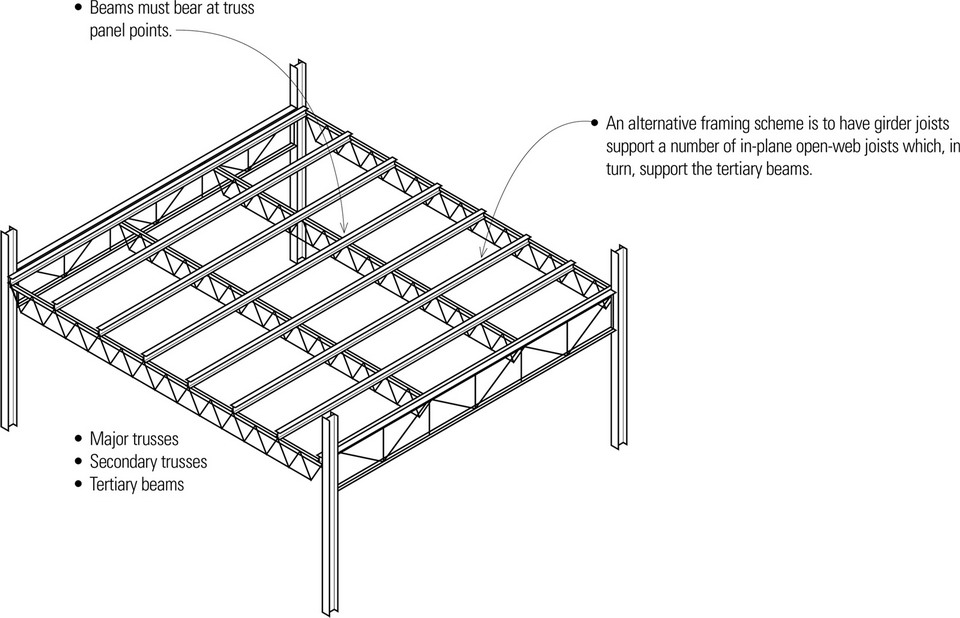
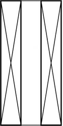
Trussed System
- Because of their standard depths and manufactured lengths, open-web joists should span rectangular bays.
Triple-Layer System
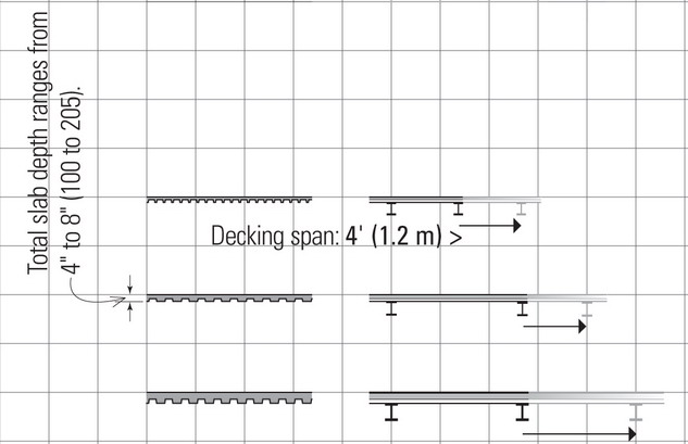
Metal Decking
Metal decking is corrugated to increase its stiffness and spanning capability. The floor deck serves as a working platform during construction and as formwork for a site-cast concrete slab.
- Form decking serves as permanent formwork for a reinforced concrete slab until the slab can support itself and its live load.

- The panels are fastened to each other along their sides with screws or welds.
- If the deck is to serve as a structural diaphragm and transfer lateral loads to shear walls, its entire perimeter must be welded to steel supports. In addition, more stringent requirements for support and side lap fastening may apply.
- In roof applications, rigid insulation can be placed directly over the steel deck in place of the concrete topping.
Grids below are based on a 3-foot (915) square.
Form Decking
- 1″ (25) spanning 3′ to 5′ (915 to 1525)
- 2″ (51) spanning 5′ to 12′ (1525 to 3660)
Composite Decking
- 1 ½″ (38) + concrete, spanning 4′ to 8′ (1220 to 2440)
- 2″ (51) + concrete, spanning 8′ to 12′ (2440 to 3660)
- 3″ (75) + concrete, spanning 8′ to 15′ (2440 to 4570)
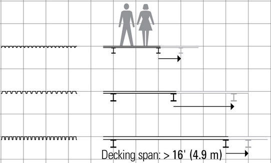
Roof Decking
- 1 ½″ (38) spanning 6′ to 12′ (1830 to 3660)
- 2″ (51) spanning 6′ to 12′ (1830 to 3660)
- 3″ (75) spanning 10′ to 16′ (3050 to 4875)
- Rule of thumb for overall depth of metal decking: span/35
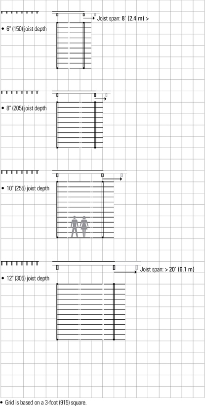
Light-Gauge Steel Joists
Light-gauge steel joists are manufactured by cold-forming sheet or strip steel. The resulting steel joists are lighter, more dimensionally stable, and can span longer distances than their wood counterparts but conduct more heat and require more energy to process and manufacture. The cold-formed steel joists can be easily cut and assembled with simple tools into a floor structure that is lightweight, noncombustible, and dampproof. As in wood light frame construction, the framing contains cavities for utilities and thermal insulation and accepts a wide range of finishes.
- Light-gauge steel joists are noncombustible and may be used in Type I and Type II construction.
- Light-gauge steel joists are laid out in and assembled in a manner similar to wood joist framing.
- Connections are made with self-drilling, self-tapping screws inserted with an electric or pneumatic tool, or with pneumatically driven pins.
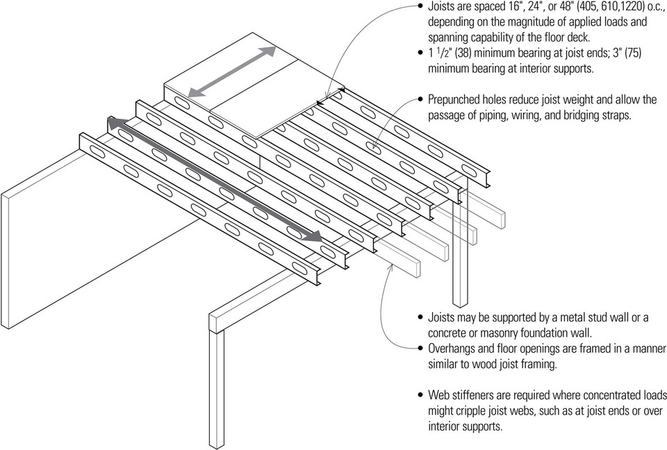
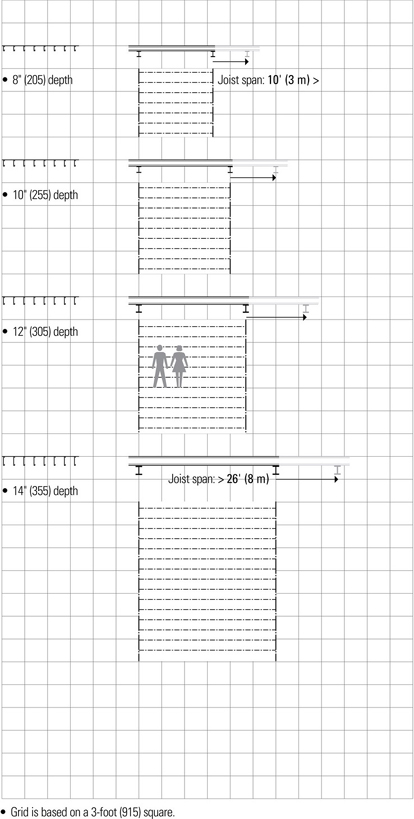
- Nominal depths: 6″, 8″, 10″, 12″, 14″ (150, 205, 255, 305, 355)
- Flange widths: 1 ½″, 1 ¾″, 2″, 2 ½″ (38, 45, 51, 64)
- Gauges: 14 through 22
- Rule of thumb for estimating joist depth: span/20
WOOD SPANNING SYSTEMS
Wood Construction
There are two distinctly different wood construction systems in current use—heavy timber framing and light wood framing. Heavy timber framing uses large, thick members such as beams and columns that have a substantially higher fire-rating than unprotected steel. Due to the scarcity of large sawn logs, most timber frames are currently composed of glue-laminated timber and parallel strand lumber rather than solid wood. Architecturally, timber framing is often left exposed for its aesthetic quality.
Light wood framing uses relatively small, closely spaced members to form assemblies that perform as structural units. The light wood members are highly flammable and must rely on finish surfacing materials for the required fire-resistance rating. The susceptibility of light wood framing to decay and insect infestation requires adequate separation from the ground, appropriate use of pressure-treated lumber, and ventilation to control condensation in enclosed spaces.
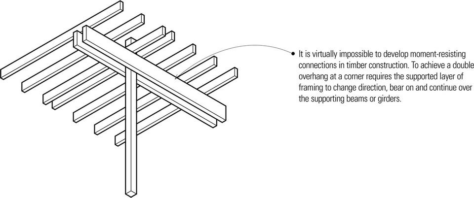
Because moment-resistant joints are difficult to achieve in wood construction, both light- and heavy-framed structures must be stabilized with either shear walls or diagonal bracing to resist lateral forces.
Wood Beams
Solid Sawn Lumber
- In the selection of a wood beam the following should be considered: lumber species, structural grade, modulus of elasticity, allowable bending and shear stress values, and the minimum deflection permitted for the intended use. In addition, attention should be paid to the precise loading conditions and the types of connections used.
- Built-up beams can be equal in strength to the sum of the strengths of the individual pieces if none of the laminations are spliced.
- Spaced beams are blocked and securely nailed at frequent intervals to enable the individual members to act as an integral unit.
- Box beams are made by gluing two or more plywood or OSB webs to sawn or LVL flanges. They can be engineered to span up to 90 feet (27 m).
Glue-Laminated Timber
- Glue-laminated timber is made by laminating stress-grade lumber with adhesive under controlled conditions, usually with the grain of all plies being parallel. The advantages of glued-laminated timber over solid-sawn lumber are generally higher allowable unit stresses, improved appearance, and availability of various sectional shapes. Glue-laminated timbers may be end-joined with scarf or finger joints to any desired length, or edge-glued for greater width or depth.
Parallel Strand Lumber
- Parallel strand lumber (PSL) is produced by bonding long, narrow wood strands together under heat and pressure using a waterproof adhesive. It is a proprietary product marketed under the trademark Parallam, used as beams and columns in post-and-beam construction and for beams, headers, and lintels in light frame construction.
Laminated Veneer Lumber
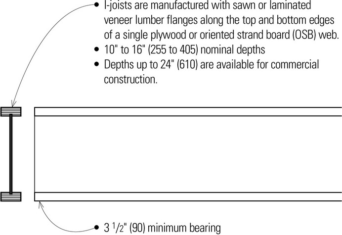
- Laminated veneer lumber (LVL) is manufactured by bonding layers of wood veneers together under heat and pressure using a waterproof adhesive. Having the grain of all veneers run in the same longitudinal direction results in a product that is strong when edge loaded as a beam or face loaded as a plank. Laminated veneer lumber is marketed under various brand names, such as Microlam, and used as headers and beams or as flanges for prefabricated wood I-joists.
Solid Wood Beams
- Available in 2″ (51) nominal increments from 4x8 to 6x12; actual dimensions are ¾″ (19) less in depth and ½″ (13) less in width than nominal.
- Rule of thumb for estimating the depth of solid wood beams: span/15
- Beam width = ⅓ to ½ of beam depth
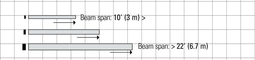
Glue-Laminated Timber
- Beam widths: 3 ⅛″, 5 ⅛″, 6 ¾″, 8 ¾″, and 10 ¾″ (80, 130, 170, 220, and 275)
- Beam depth is in multiples of 1 ⅜″ or 1 ½″ (35 or 38) laminations up to 75″ (19 050). Curved members can be laminated in ¾″ (19) laminations to create tighter curvature.
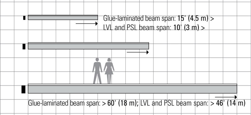
Parallel Strand Lumber
- Beam widths: 3 ½″, 5 ¼″, and 7″ (90, 135, and 180)
- Beam depths: 9 ½″, 11 ⅞″, 14″, 16″, and 18″ (240, 300, 355, 410, and 460)
Laminated Veneer Lumber
- 1 ¾″ (45) beam width; can be laminated for greater widths.
- 5 ½″, 7 ¼″, 9 ¼″, 11 ¼″, 11 ⅞″, 14″, 16″, 18″, and 20″ (140, 185, 235, 285, 300, 355, 405, 455, and 510) beam depths
- Rule of thumb for estimating the depth of manufactured beams: span/20
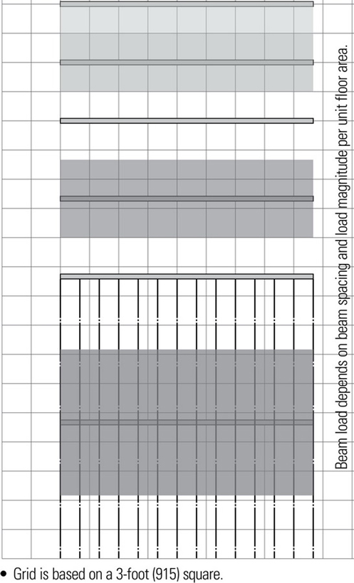
- Beam spans are only estimates. Any accurate calculation of beam size must take into account the tributary load area for a beam, based on its spacing and the magnitude of load being carried.
- Beam width should be ¼ to ⅓ of beam depth
- Because of transport limitations, the maximum standard length for manufactured beams is 60′ (18 m).
Plank-and-Beam Systems
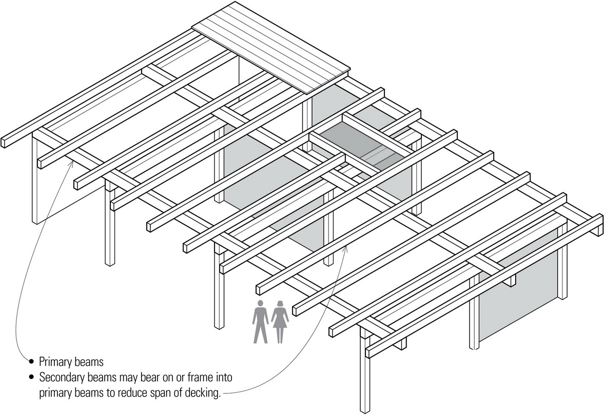
Wood plank-and-beam spanning systems are typically used with a supporting grid of columns to form a skeleton frame structure. Using larger but fewer structural members that can span greater distances translates into potential savings in material and labor costs.
- Plank-and-beam framing is most effective when supporting moderate, evenly distributed loads; concentrated loads may require additional framing.
- When this structural system is left exposed, as is often the case, careful attention must be paid to the species and grade of wood used, the detailing of joints, especially at beam-to-beam and beam-to-post connections, and the quality of workmanship.
Plank-and-beam framing may qualify as heavy timber construction if the structure is supported by noncombustible, fire-resistive exterior walls and the members and decking meet the minimum size requirements specified in the building code. Disadvantages of the plank-and-beam floor system include its susceptibility to impact sound transmission, and its inherent lack of concealed spaces for thermal insulation, piping, wiring, and ductwork.
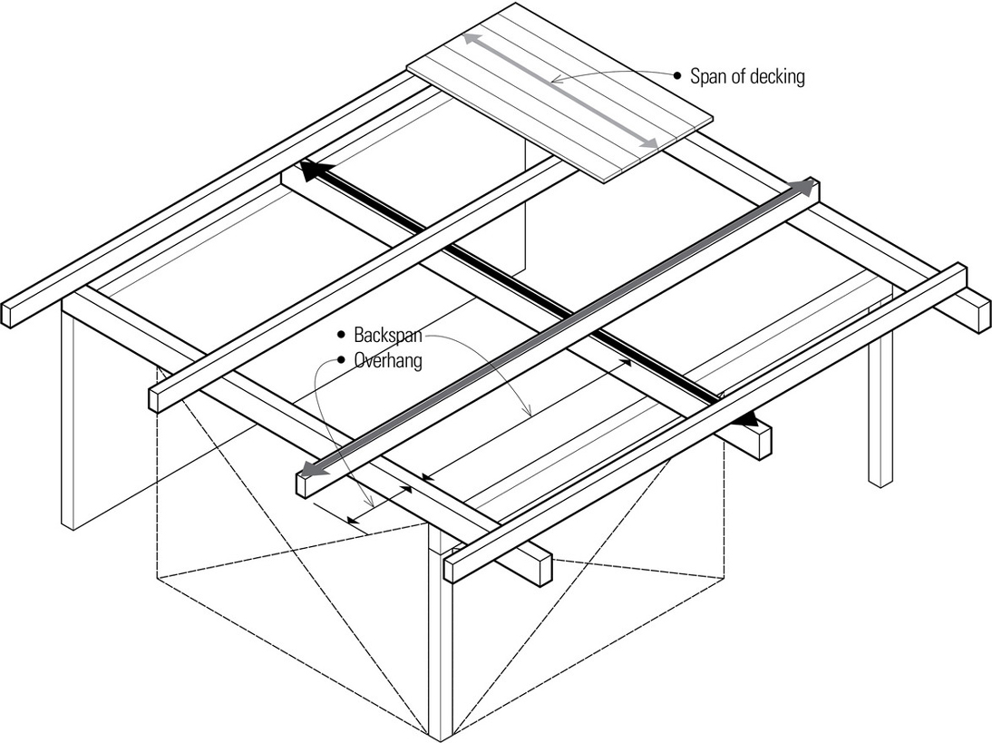
- Note that every layer of one-way spanning elements must be laid perpendicular to the supporting layer below as well as the supported layer above.
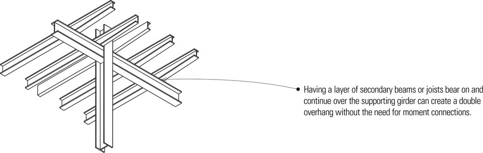
- Overhangs are possible if beams bear on and continue over their end support; limit to a quarter of the backspan.
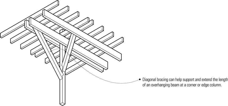
- Diagonal bracing or shear walls are required to provide lateral stability. It is not possible to develop moment-resistant connections in timber post-and-beam framing.
- The supporting grid of beams should be carefully integrated with the required placement of interior partitions for both structural and visual reasons.
- Any bearing partitions should continue down to a foundation wall or be placed directly over beams large enough to carry the imposed load.
- Openings and concentrated loads require additional framing.
- A variety of metal attachments are manufactured for wood-to-wood, wood-to-metal, and wood-to-masonry connections. These include joist and beam hangers, post bases and caps, framing angles and anchors, and floor ties and holddowns. Some provide resistance to both uplift and horizontal forces. Depending on the magnitude of the loads being resisted or transferred, the connectors may be nailed or bolted.
Wood Decking
Wood decking is typically used with plank-and-beam systems but can also form the surface layer of steel frame construction. The underside of the decking may be left exposed as a finished ceiling surface.
Types of Wood Decking
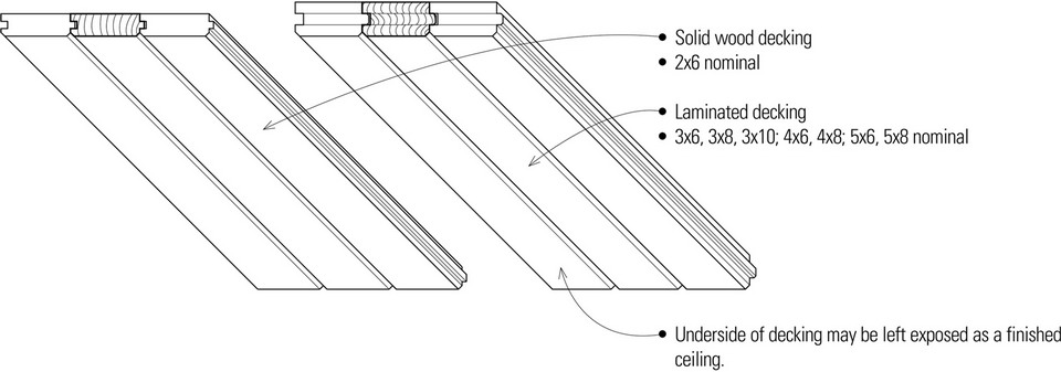
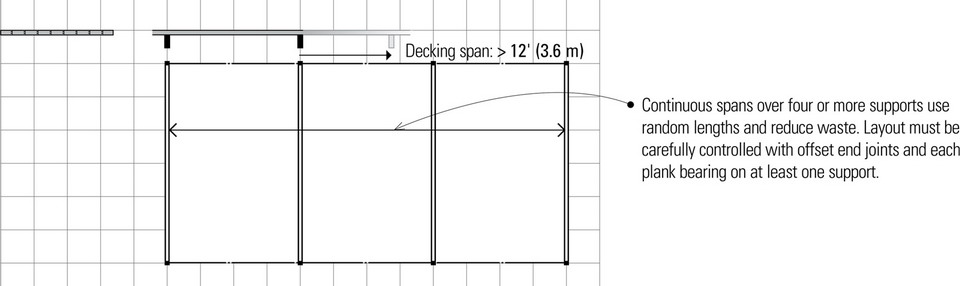
- Other options for the surface layer include 2-4-1 plywood or prefabricated stressed-skin panels.
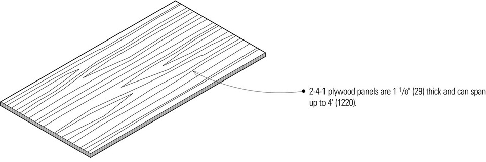
- Panels are laid continuously over two spans with face plies perpendicular to beams and end joints staggered.
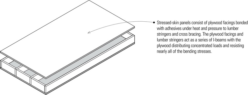
- Panels integrate thermal insulation, a vapor retarder, and an interior finish into a single component.
- Wood decking is most effective in supporting uniform loads. Openings and concentrated loads may require additional framing.
- Limited overhangs are possible.
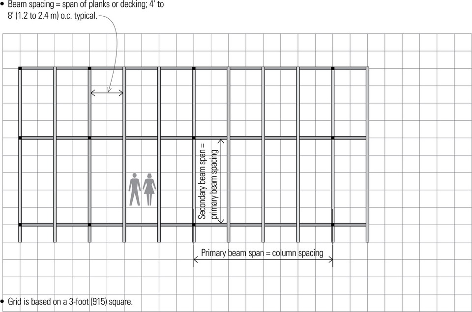
- Wood decking can span up to 12′ (3.6 m), but the most common span range is 4′ to 8′ (1.2 to 2.4 m).
- Rule of thumb for estimating depth of decking: span/30.
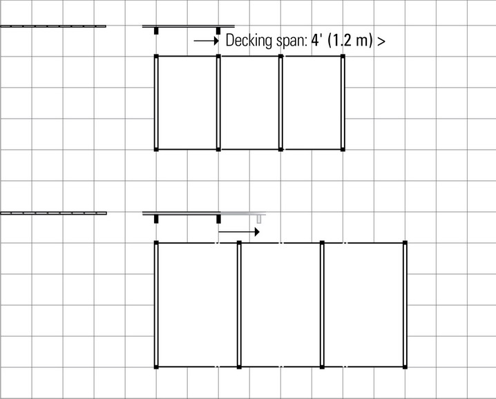
Types of Spans
Both the moment-resisting capacity and deflection of wood decking are affected by the manner in which they are laid.
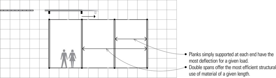
- Grid is based on a 3-foot (915) square.
Wood Joists
The term joist refers to any of various spanning members designed for closely spaced, multiple member spanning assemblies. The close spacing of joists results in a relatively small tributary load area for each member and a distributed load pattern on the supporting beam or wall.

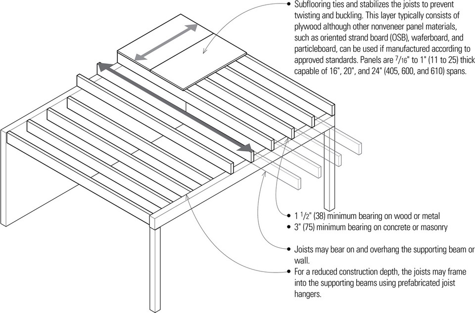
Wood joists are an essential subsystem of light wood frame construction. The dimension lumber used for joists is easily worked and can be quickly assembled on-site with simple tools. Together with wood panel sheathing or subflooring, the wood joists form a level working platform for construction. If properly engineered, the resulting floor structure can serve as a structural diaphragm to transfer lateral loads to shear walls.
- Joists are spaced 12″, 16″, or 24″ ( 305, 405, or 610) o.c., depending on the anticipated magnitude of applied load and spanning capability of the subflooring or sheathing.
- A ceiling may be applied directly to joists, or be suspended to lower ceiling area or conceal mechanical runs perpendicular to joists.
- Because wood light framing is combustible, it must rely on finish flooring and ceiling materials for its fire-resistance rating.
- Joist ends require lateral support.
- Wood joist framing is highly flexible and well suited for irregular layouts due to the workability of the material.
- Wood joist sizes: 2x6, 2x8, 2x10, and 2x12 nominal
- Dressed sizes of joists:
Subtract ½″ (13) from nominal dimensions of 2″ to 6″ (51 to 150);
Subtract ¾″ (19) from nominal dimensions greater than 6″ (150).
- Span ranges for wood joists:
2x6 up to 10′ (3 m)
2x8 8′–12′ (2.4–3.6 m)
2x10 10′–14′ (3–4.3 m)
2x12 12′–20′ (3.6–6.1 m) - Rule of thumb for estimating joist depth: span/16
- Solid wood joists are available in lengths up to 20′ (6 m).
- The stiffness of the joist framing under stress is often more critical than its strength as the joist members approach the limit of their span range.
- If the overall construction depth is acceptable, deeper joists spaced farther apart are more desirable for stiffness than shallow joists spaced more closely together.
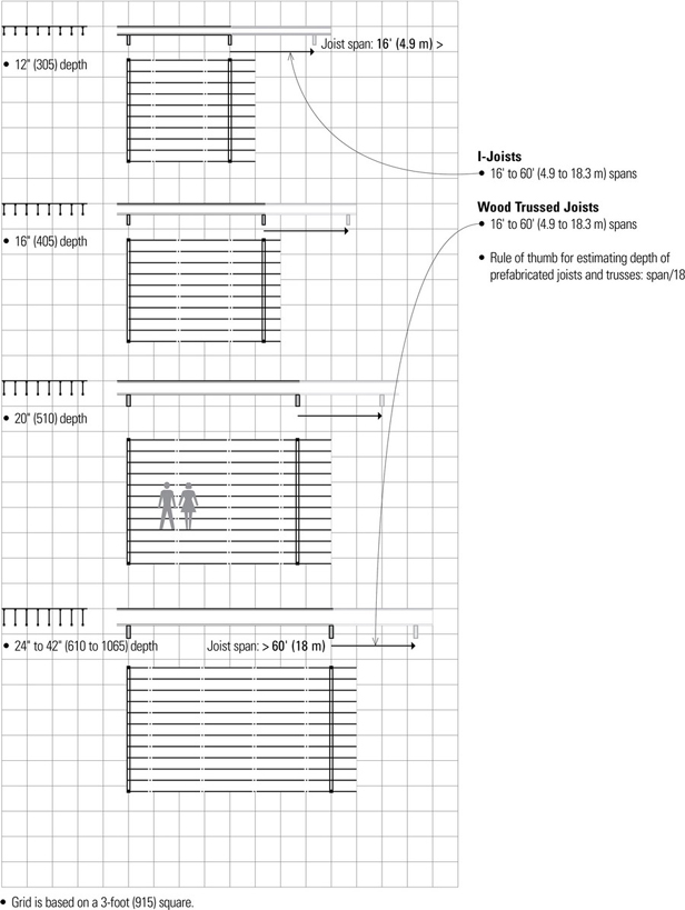
Prefabricated Joists and Trusses
Prefabricated, pre-engineered wood joists and trusses are increasingly used in the place of dimension lumber to frame floors and roofs because they are generally lighter and more dimensionally stable than sawn lumber, are manufactured in greater depths and lengths, and can span longer distances. While the precise form of a prefabricated floor joist or truss varies with the manufacturer, the way they are laid out to frame a floor is similar in principle to conventional wood joist framing. They are most appropriate for long spans and simple floor plans; complex floor layouts may be difficult to frame.
I-Joists
- Double joists provide support for parallel bearing partitions.
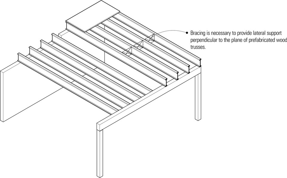
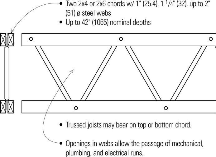
Wood Trussed Joists
CANTILEVERS
Cantilevers
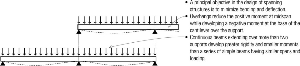
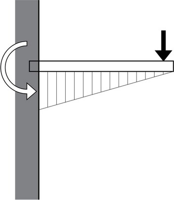
A cantilever is a beam, girder, truss, or other rigid structural framework that is securely fixed at one end and free at the other end. The fixed end of a cantilever resists loads transversely and rotationally while the other end is free to deflect and rotate. Pure cantilever beams exhibit a single downward curvature when loaded from above. The top surface of the beam will be stressed in tension while the bottom fibers are subjected to compressive stresses. Cantilever beams tend to have very large deflections and the critical bending moment develops at the support.
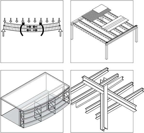
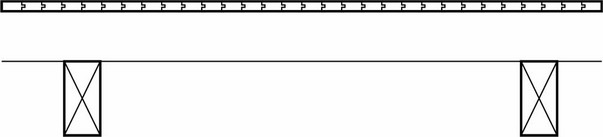
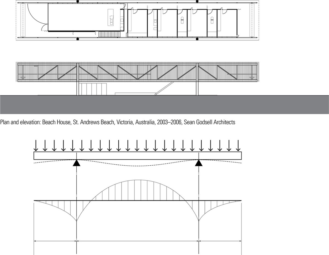
Overhanging Beams
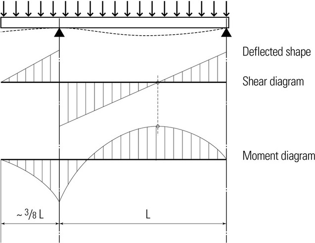
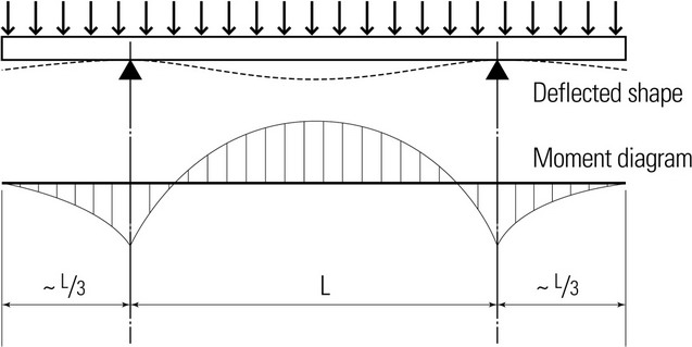
An overhanging beam is formed by extending one or both ends of a simple beam. Cantilever action results from the beam extension, which has the positive effect of counteracting the deflection present in the interior span. Overhanging beams exhibit multiple curvatures, unlike a simple cantilever beam. Tensile and compressive stresses reverse along the beam’s length corresponding to the deflected shape.
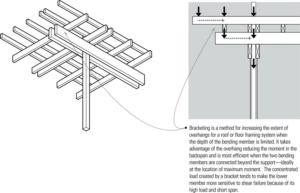
- Assuming a uniformly distributed load, the projection of a single overhanging beam for which the moment over the support is equal and opposite to the moment at midspan is approximately 3/8 of the span.
- Assuming a uniformly distributed load, the projections of a double overhanding beam for which the moments over the supports are equal and opposite to the moment at midspan are approximately 1/3 of the span.
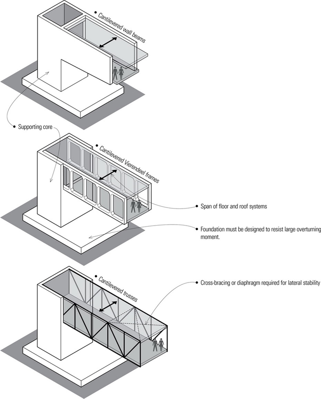
Cantilevered Buildings
Cantilevered and overhanging structures are commonly used to form a range of building components, from balconies and roof eaves to the larger-scale structures of stadium roofs. Even large portions of buildings can cantilever or overhang beyond the line of vertical column or wall supports.
The major horizontal structural elements for larger building cantilevers or overhangs may be wall beams, Vierendeel frames, or trusses, often one or more stories in depth. These horizontal structures, in turn, are supported by one or more cores, which typically contain the vertical transport and supply systems. Parallel steel trusses overhanging a concrete core appear to be the most common strategy applied in many contemporary buildings.
St. Andrew’s Beach House exemplifies a double overhanging beam formed by extending both ends of a simple beam. In this case, a pair of full-length, story-high trusses, linked by the floor and roof framing, defines and raises the volume of the main living level above the ground for better views and to provide space below for cars and storage. The cantilever action results from the extension of the trusses beyond their column supports, which has the positive effect of counteracting the deflection present in the interior span.

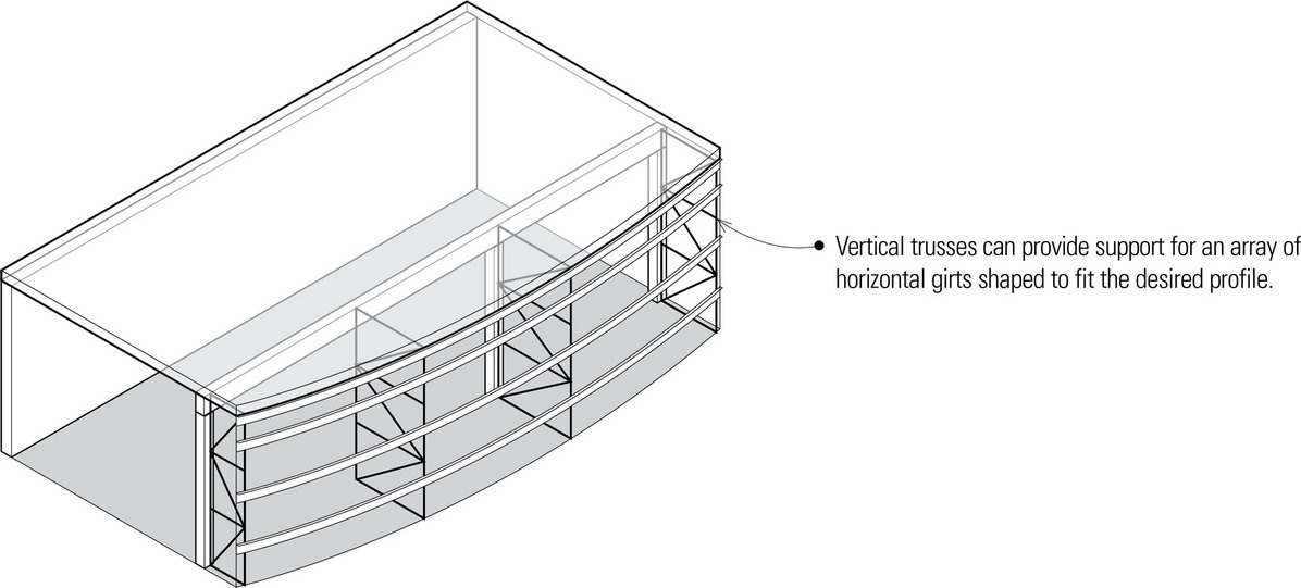
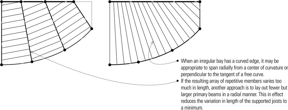
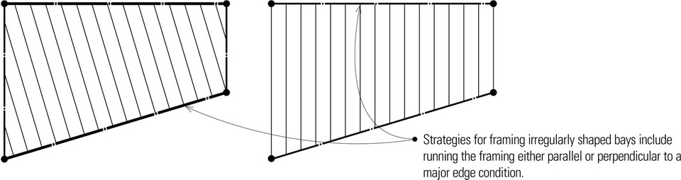
IRREGULAR BAYS
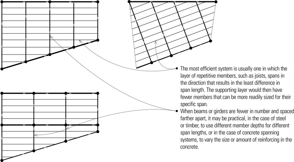
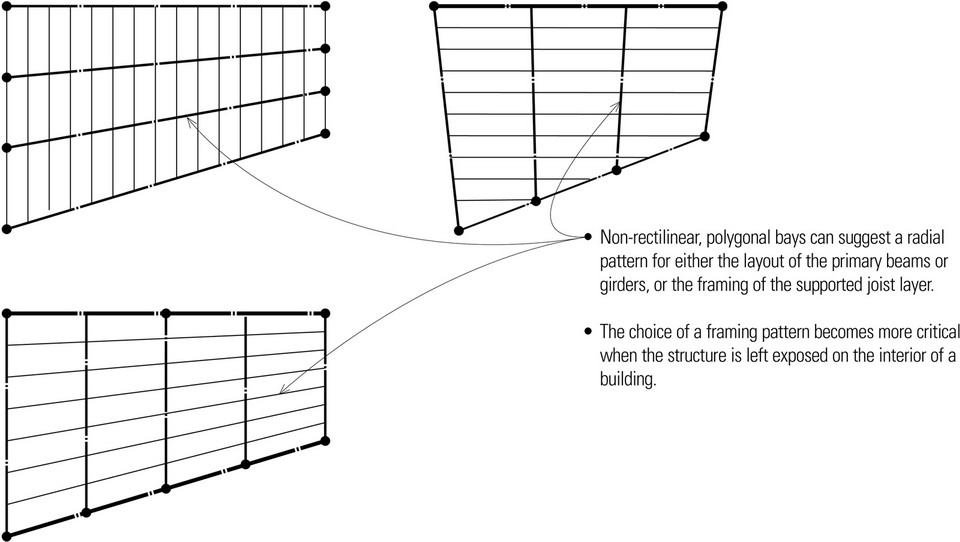
One-way spanning systems are most efficient when spanning regular, rectangular bays. In the case of two-way systems, the structural bays should not only be regular but also as nearly square as possible. Using regular bays also allows the use of repetitive members of identical cross section and length, which results in an economy of scale. However, programmatic requirements, contextual constraints, or aesthetic initiatives can often suggest the development of structural bays that are neither rectangular nor geometrically regular.
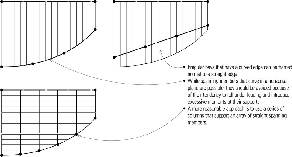
Whatever the reason for their being, irregularly shaped bays do not often exist in isolation. They often are formed along the periphery of a more regular grid or pattern of supports and spanning elements. Nevertheless, irregularly shaped bays will nearly always result in some structural inefficiency, as the spanning members must be designed for the longest span in each layer even though the lengths of each spanning member may vary.
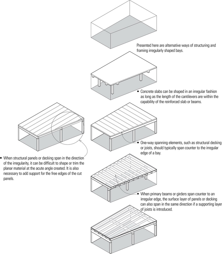
- It is usually difficult to vary the depth of one-way spanning members in a single layer. The span of the longest member therefore determines the size of all of the remaining members in the same layer.
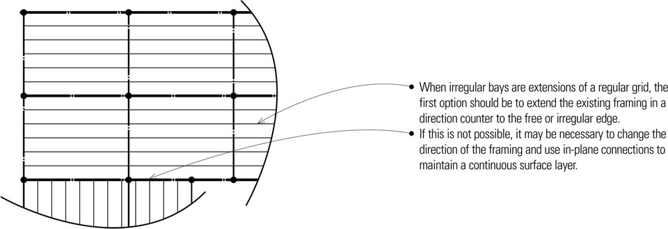
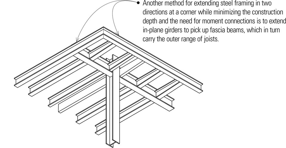
- Additional supports may be necessary if the extent of the free or irregular edge is greater than the overhanging or cantilevering capability of the spanning members.