4
Vertical Dimensions
VERTICAL DIMENSIONS
This chapter addresses the vertical dimensions of building structures—the vertical supports for horizontal spanning systems and the vertical systems of enclosure that provide shelter and protection from the climatic elements and aid in controlling the flow of air, heat, and sound into and through the interior spaces of a building.
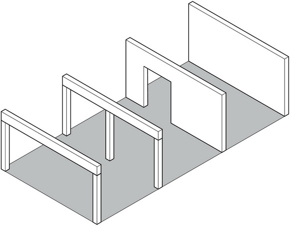
The pattern of horizontal spanning systems must, of course, be intimately related to the pattern of vertical supports, be they an array of columns and beams, a parallel series of bearing walls, or a combination of both. The pattern of these vertical supports should, in turn, be coordinated with the desired form and layout of the interior spaces of a building. Both columns and walls have a greater presence in our visual field than horizontal planes and are therefore more instrumental in defining a discrete volume of space and providing a sense of enclosure and privacy for those within it. In addition, they serve to separate one space from another and establish a common boundary between the interior and exterior environments.
The reason roof structures are included in this chapter rather than the previous chapter is that, while roof structures necessarily are inherently spanning systems, they have a vertical aspect that must be considered in terms of the impact they might have on the external form of buildings as well as the shaping of interior space.
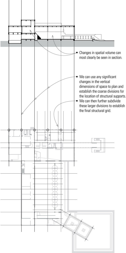
- During the design process, we use plans, sections, and elevations to establish two-dimensional planar fields on which we are able to study formal patterns and scale relationships in a composition, as well as impose an intellectual order on a design. Any single multiview drawing, whether it be a plan, a section, or an elevation, can only reveal partial information about a three-dimensional idea, structure, or construction. There is an inherent ambiguity of depth as the third dimension is flattened in these views. We therefore require a series of distinct but related views to fully describe the three-dimensional nature of a form, structure, or composition.
Building Scale
We can categorize the vertical scale of buildings into low-rise, mid-rise, and high-rise structures. Low-rise structures generally have one, two, or three stories and no elevator; mid-rise structures have a moderately large number of stories, usually five to ten floors, and are equipped with elevators; and high-rise structures have a comparatively large number of stories and must be equipped with elevators. It is useful to think in these categories when selecting and designing a structural system because the scale of a building is directly related to the type of construction required and the uses or occupancies allowed by the building code.
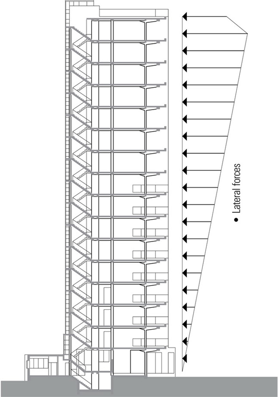
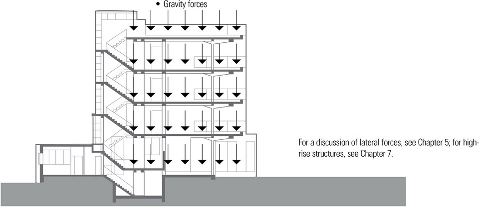
The vertical scale of a building also influences the selection and design of a structural system. For low-rise and short-span structures constructed of relatively heavy materials, such as concrete, masonry, or steel, the primary determinant of the structural form is typically the magnitude of the live load. For long-span structures constructed of similar materials, the dead load of the structure may be the principal factor in establishing the structural strategy. As buildings become taller, however, not only do gravity loads accumulate over a large number of stories but lateral wind and seismic forces become critical issues to address in the development of the overall structural system.
Human Scale
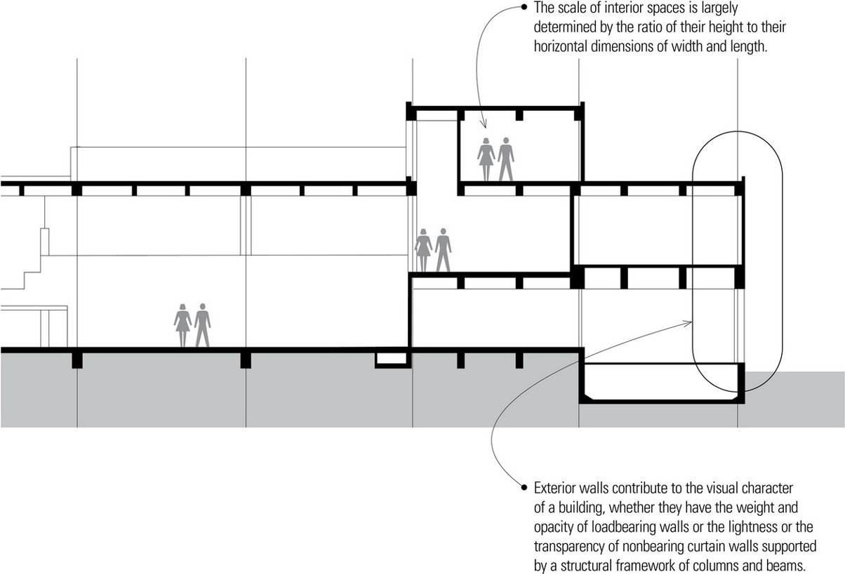
Of a room’s three dimensions, its height has a greater effect on its scale than either its width or length. While the walls of the room provide enclosure, the height of the ceiling plane overhead determines its qualities of shelter and intimacy. Raising the ceiling height of a space will be more noticeable and affect its scale more than increasing its width by a similar amount. While a modest room with a normal ceiling height might feel comfortable to most people, a large assembly space with a similar ceiling height would likely feel oppressive. Columns and bearing walls must be of sufficient height to establish the desired scale of a building story or a single space within the building. As their unsupported height increases, columns and bearing walls must necessarily become thicker to maintain their stability.
Exterior Walls
Walls are the vertical constructions that enclose, separate, and protect the interior spaces of buildings. They may be loadbearing structures of homogeneous or composite construction designed to support imposed loads from floors and roofs, or consist of a framework of columns and beams with nonstructural panels attached to or filling in between them. The interior walls or partitions, which subdivide the space within a building, may be either structural or nonloadbearing. Their construction should be able to support the desired finish materials, provide the required degree of acoustical separation, and accommodate when necessary the distribution and outlets of mechanical and electrical services.
Openings for doors and windows must be constructed so that any vertical loads from above are distributed around the openings and not transferred to the door and window units themselves. Their size and location are determined by the requirements for natural light, ventilation, view, and physical access, as well as the constraints of the structural system and modular wall materials.
Roof Structures
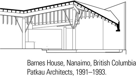
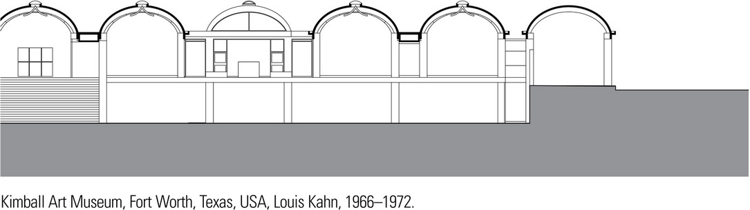
The principal sheltering element of a building is its roof structure. It not only shields the interior spaces of a building from sun, rain, and snow, but it also has a major impact on the overall form of a building and the shaping of its spaces. The form and geometry of the roof structure, in turn, is established by the manner in which it spans across space to bear on its supports and slopes to shed rain and melting snow. As a design element, the roof plane is significant because of the impact it can have on the form and silhouette of a building within its setting.
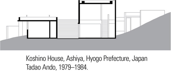
The roof plane can be hidden from view by the exterior walls of a building or merge with the walls to emphasize the volume of the building mass. It can be expressed as a single sheltering form that encompasses a variety of spaces beneath its canopy, or comprise a number of hats that articulate a series of spaces within a single building.
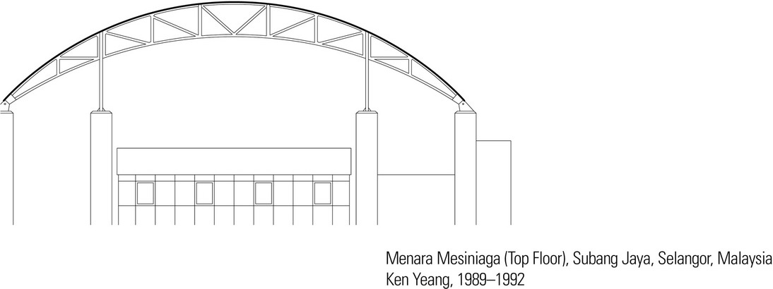
A roof plane can extend outward to form overhangs that shield door and window openings from sun or rain, or continue downward further still to relate itself more closely to the ground plane. In warm climates, it can be elevated to allow cooling breezes to flow across and through the interior spaces of a building.
VERTICAL SUPPORTS
Throughout history, developments in building materials and construction technology have resulted in the transformation of vertical supports for buildings, from bearing walls of stacked stones to masonry walls penetrated with linteled or arched openings, from post-and-beam frames of timber to rigid frames of reinforced concrete and steel.
Because exterior walls serve as a protective shield against the weather for the interior spaces of a building, their construction should control the passage of heat, infiltrating air, sound, moisture, and water vapor. The exterior skin, which may be either applied to or integral with the wall structure, should be durable and resistant to the weathering effects of sun, wind, and rain. Building codes specify the fire-resistance rating of exterior walls, loadbearing walls, and interior partitions. In addition to supporting vertical loads, exterior wall constructions must be able to withstand horizontal wind loading. If rigid enough, they can serve as shear walls and transfer lateral wind and seismic forces to the ground foundation.
- Transformation from bearing walls capable of carrying imposed floor and roof loads to a structural framework of columns and beams.
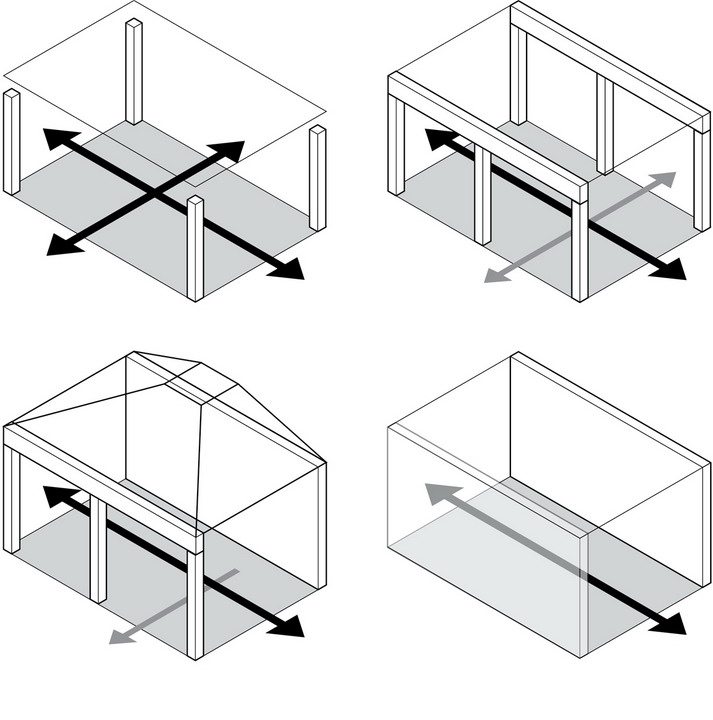
Columns and walls have a greater presence in our visual field than horizontal planes and are therefore more instrumental in defining a discrete volume of space and providing a sense of enclosure and privacy for those within it. For example, a structural frame of timber, steel, or concrete columns and beams would give us the opportunity to establish relationships with adjacent spaces on all four sides of the volume. To provide enclosure, we could use any number of nonloadbearing panel or wall systems that would be tied to the structural frame and designed to withstand wind, shear, and other lateral forces.
- Also influencing the physical qualities of a space is the ceiling plane, which is out of our reach and almost always a purely visual event. It can express the form of an overhead floor or roof structure as it spans the space between its supports, or be suspended as a detached lining to alter the scale of a space or to define spatial zones within a room.
If a pair of parallel bearing walls of masonry or concrete were used instead of the structural frame, then the volume would take on a directional quality and be oriented toward the open ends of the space. Any openings in the bearing walls would have to be limited in size and location so as not to weaken the walls’ structural integrity. If all four sides of the volume were enclosed by bearing walls, the space would become introverted and rely entirely on openings to establish relationships with adjacent spaces.
In all three cases, the spanning system required to provide overhead shelter could be flat or sloped in any number of ways, further modifying the spatial and formal qualities of the volume.
Structural Frames
- Concrete frames are typically rigid frames and qualify as noncombustible, fire-resistive construction.
- Noncombustible steel frames may use moment connections and require fireproofing to qualify as fire-resistive construction.
- Timber frames require diagonal bracing or shear planes for lateral stability. They may qualify as heavy timber construction if used with noncombustible, fire-resistive exterior walls and the members meet the minimum size requirements specified in the building code.
- Steel and concrete frames are able to span greater distances and carry heavier loads than timber structures.
- Structural frames can support and accept a variety of nonbearing or curtain-wall systems.
- The detailing of connections is critical for structural and visual reasons when the frame is left exposed.
Concrete and Masonry Bearing Walls
- Concrete and masonry walls qualify as noncombustible construction and rely on their mass for their load-carrying capability.
- While strong in compression, concrete and masonry require reinforcing to handle tensile stresses.
- Height-to-width ratio, provisions for lateral stability, and proper placement of expansion joints are critical factors in wall design and construction.
- Wall surfaces may be left exposed.
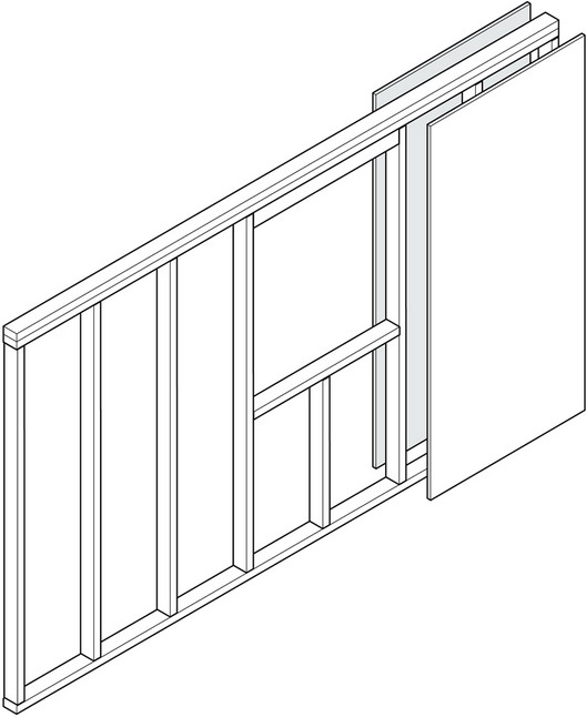
Metal and Wood Stud Walls
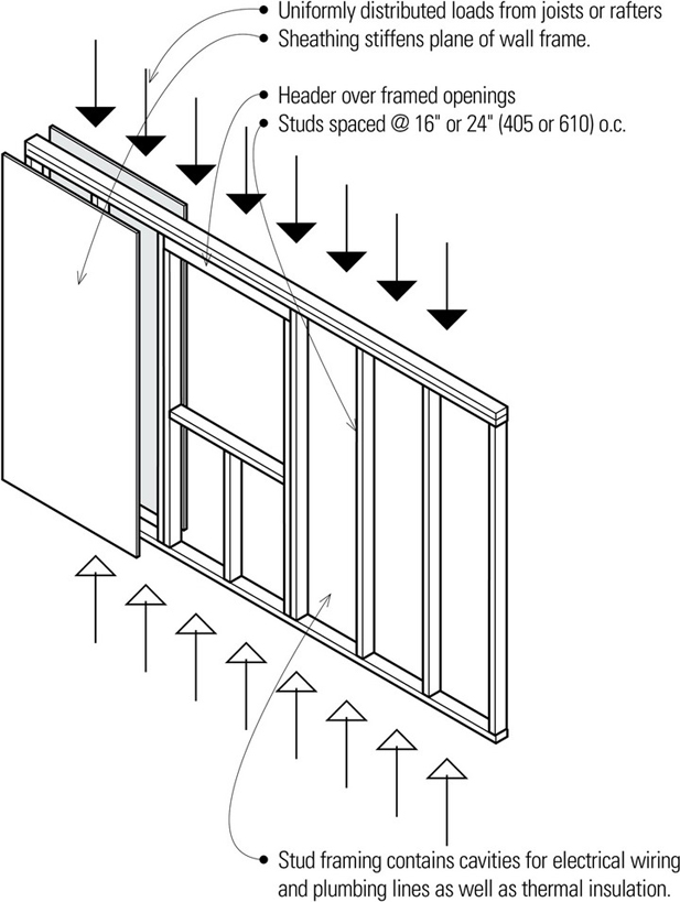
- Studs of cold-formed metal or wood are normally spaced @ 16″ or 24″ (406 or 610) o.c.; this spacing is related to the width and length of common sheathing materials.
- Studs carry vertical loads while sheathing or diagonal bracing stiffens the plane of the wall.
- Cavities in the wall frame can accommodate thermal insulation, vapor retarders, and mechanical distribution and outlets of mechanical and electrical services.
- Stud framing can accept a variety of interior and exterior wall finishes; some finishes require a nail-base sheathing.
- The finish materials determine the fire-resistance rating of the wall assembly.
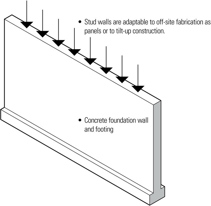
- Stud wall frames may be assembled on-site or panelized off-site.
- Stud walls are flexible in form due to the workability of relatively small pieces and the various means of fastening available.
Tributary Loads
Determining the tributary area for loads on vertical supports must take into account the layout of the structural grid and the type and pattern of horizontal spanning systems being supported. Bearing walls and columns are designed to collect gravity loads from trusses, girders, beams, and slabs and redirect these loads vertically down to the foundation. Braced frames, rigid frames, and shear walls may also induce lateral loads on bearing walls and columns, which have to be redirected downward in a vertical direction.
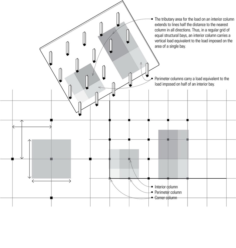
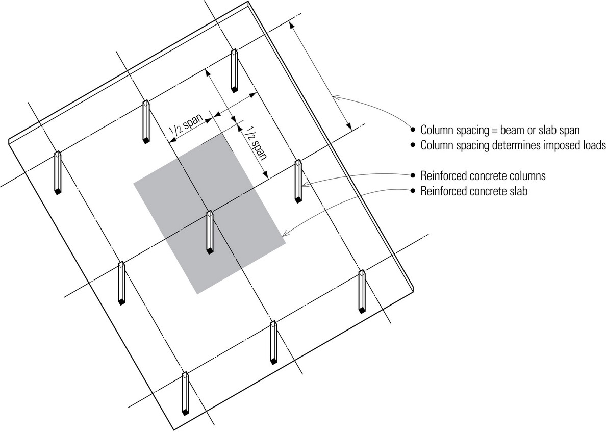
- The tributary area of the gravity load on a particular bearing wall or column is determined by the distance from the bearing wall or column to adjacent vertical supports, which is equivalent to the length of the span of the floor or roof structure being carried.
- Omitting a column from the grid essentially transfers the load it would have carried to adjacent columns. This also results in a doubling of the floor or roof span and deeper spanning members.
- Columns located at outside corners carry the equivalent of one-fourth of the load of an interior bay.
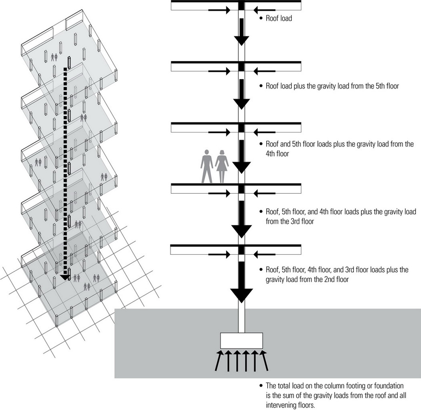
Load Accumulation
Columns redirect the gravity loads collected from beams and girders as vertical concentrated loads. In multistory buildings these gravity loads accumulate and increase as they are directed downward along bearing walls and columns through successive floors from the roof through to the foundation.
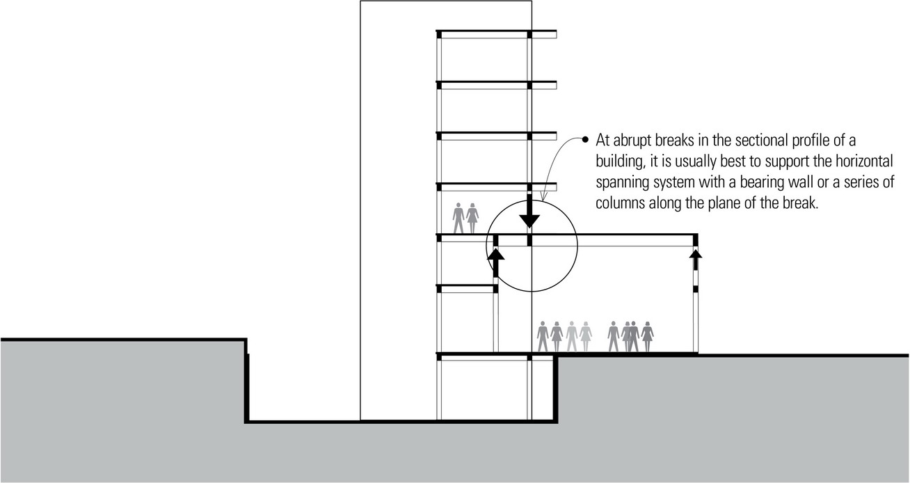
Vertical Continuity
The most efficient path for gravity loads is directly downward through vertically aligned columns and bearing walls to the foundation. This means that the same grid should control the placement of vertical supports for all of the floor structures as well as the roof structure of a building. Any deviation in the path of a vertical load requires that the load be redirected horizontally through a transfer beam or truss to alternative vertical supports, resulting in an increased load and depth for the spanning member.
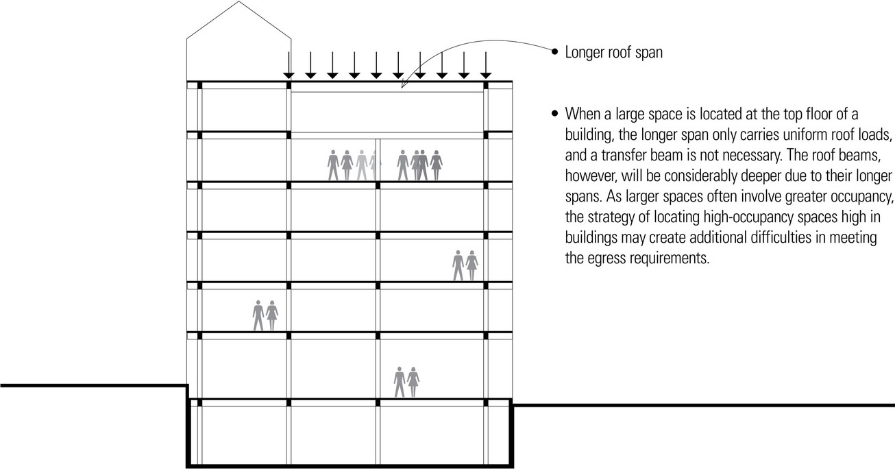
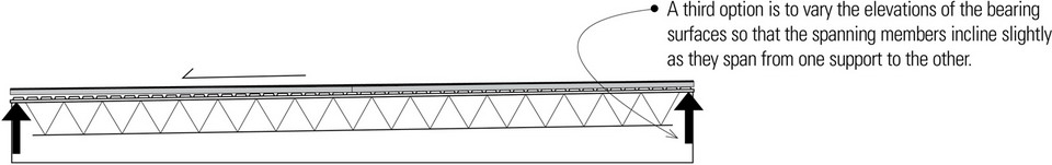
While a regular grid of vertically aligned supports is always desirable, a design program may call for a spatial volume much larger than can be accommodated by the normal grid spacing. Illustrated on this and the facing page are several options for accommodating exceptionally large spaces within a building.
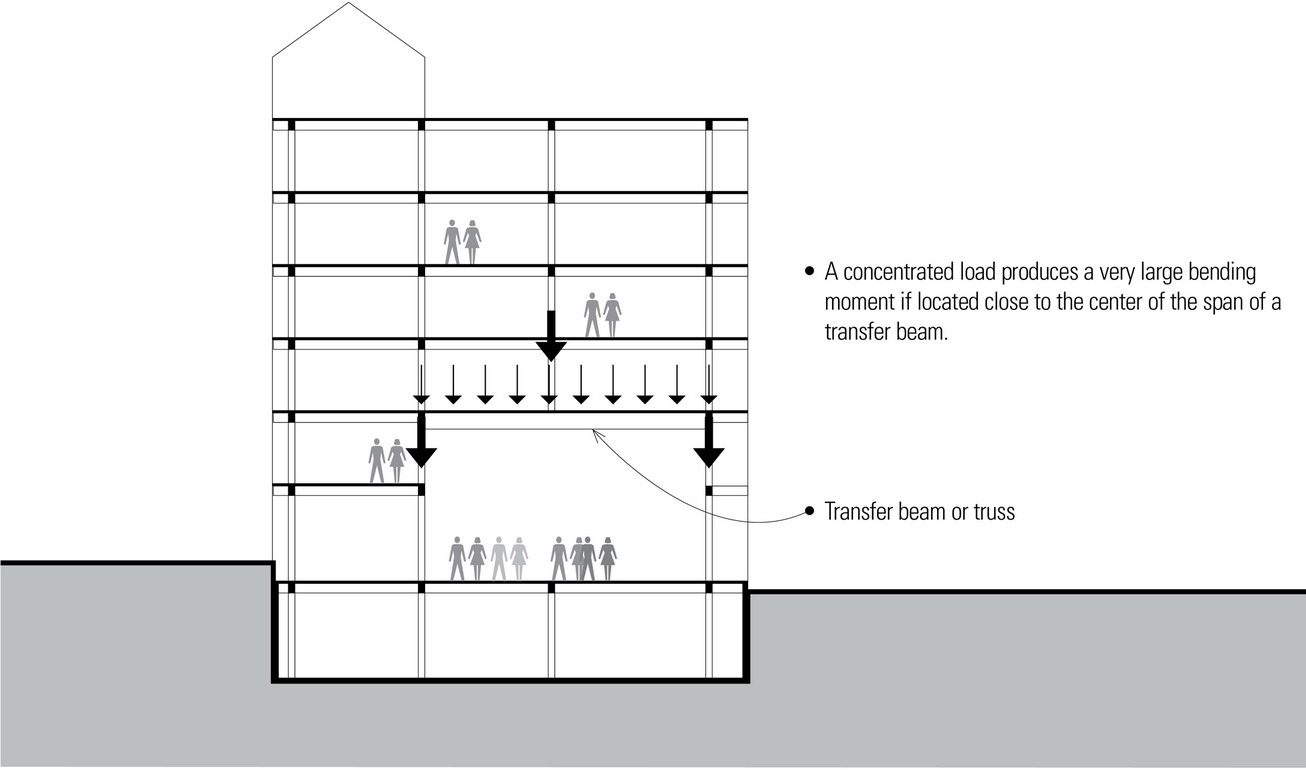
- Transfer beams or trusses are often required to accommodate spaces that require exceptional volume or larger clear spans within a more regular bay spacing.
- Transfer beams should have as short a span as possible.
- A concentrated load applied close to the end support of a transfer beam generates extremely high shear forces.
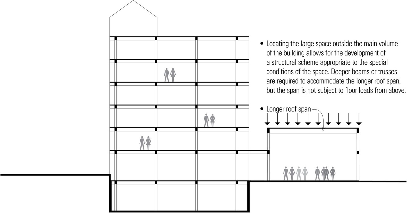
- Locating a large space below multiple floors requires transfer beams to carry the gravity loads from the upper floors and transfer them to supporting columns, which must be enlarged to accommodate the increased load.
COLUMNS
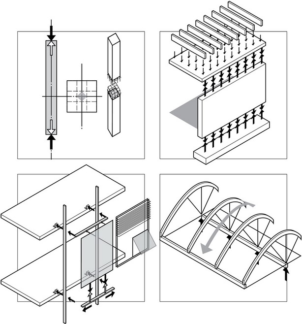
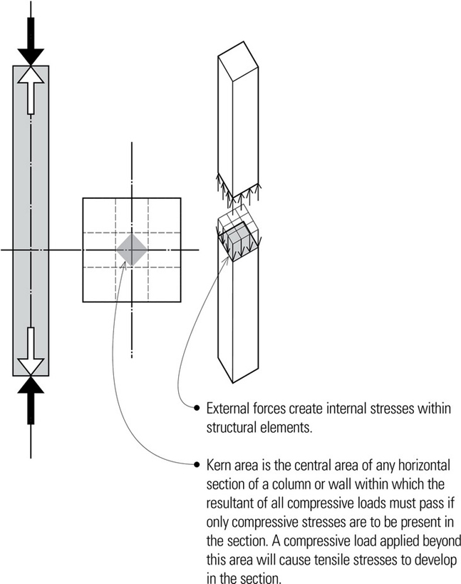
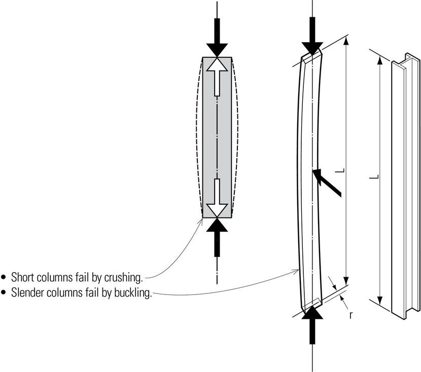
Columns are rigid, relatively slender structural members designed primarily to support axial compressive loads applied to the ends of the members. Relatively short, thick columns are subject to failure by crushing rather than by buckling. Failure occurs when the direct stress from an axial load exceeds the compressive strength of the material available in the cross section. An eccentric load, however, can produce bending and result in an uneven stress distribution in the section.
Long, slender columns are subject to failure by buckling rather than by crushing. As opposed to bending, buckling is the sudden lateral or torsional instability of a slender structural member induced by the action of an axial load before the elastic limit of the material is reached. Under a buckling load, a column begins to deflect laterally and cannot generate the internal forces necessary to restore its original linear condition. Any additional loading would cause the column to deflect further until collapse occurs in bending. The higher the slenderness ratio of a column, the lower is the critical stress that will cause it to buckle. A primary objective in the design of a column is to reduce its slenderness ratio by shortening its effective length or maximizing the radius of gyration of its cross section.
Intermediate columns have a mode of failure between that of a short column and a long column, often partly inelastic by crushing and partly elastic by buckling.
- Radius of gyration (r) is the distance from an axis at which the mass of a body may be assumed to be concentrated. For a column section, the radius of gyration is equal to the square root of the quotient of the moment of inertia and the area.
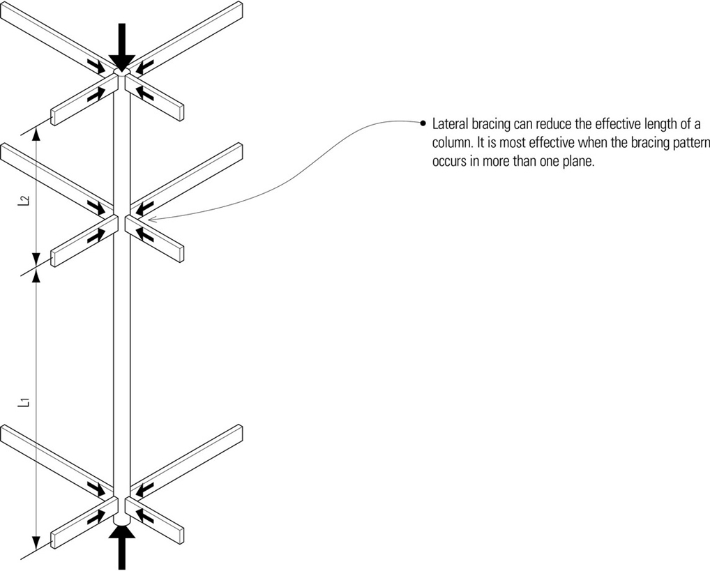
- The slenderness ratio of a column is the ratio of its effective length (L) to its least radius of gyration.
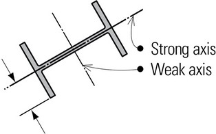
- For asymmetrical column sections, buckling will tend to occur about the weaker axis or in the direction of the least dimension.
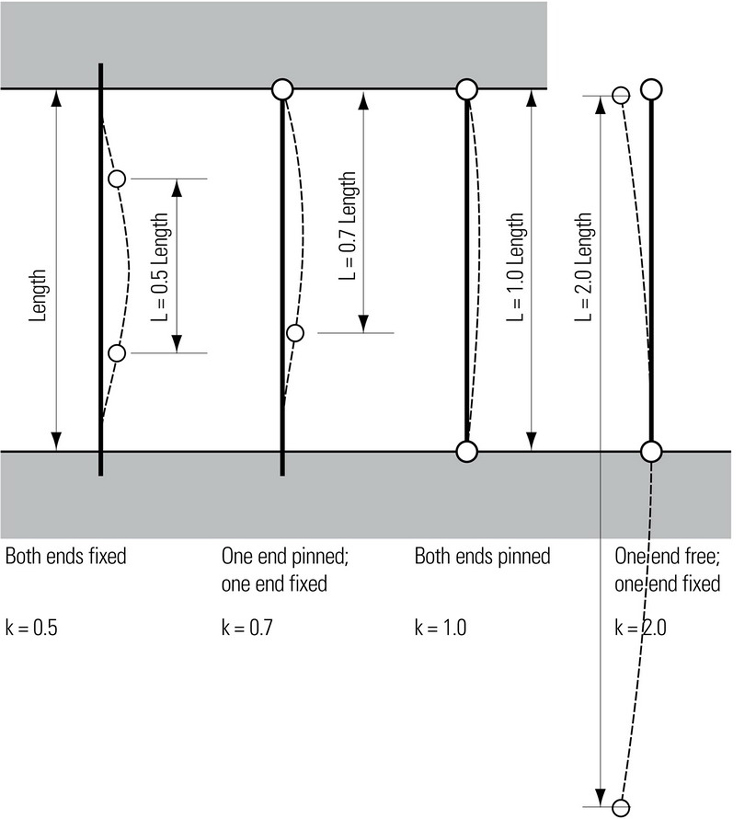
Effective length (L) is the distance between hinge and/or inflection points in a column subject to buckling. When this portion of a column buckles, the entire column fails. The effective length factor (k) is a coefficient for modifying the actual length of a column according to its end conditions in order to determine its effective length. Fixing both ends of a long column reduces its effective length by half and increases its load-carrying capacity by a factor of 4.
- In general, the most efficient column cross sections for axial loads are those having an equal radius of gyration about the x- and y-axes. Both axes are equivalent and thus result in the same slenderness ratio for the column.
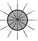
- A circular cross section possesses an unlimited number of buckling axes, all being equal. None is weaker or stronger than the others.
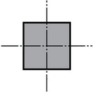
- A square cross section has the same radius of gyration and slenderness ratio about the x- and y-axes and so buckling could result about either axis.
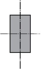
- A rectangular cross section has two different radii of gyration. The smaller radius of gyration about its weaker axis produces a larger slenderness ratio, thereby resulting in a smaller axial load capacity.
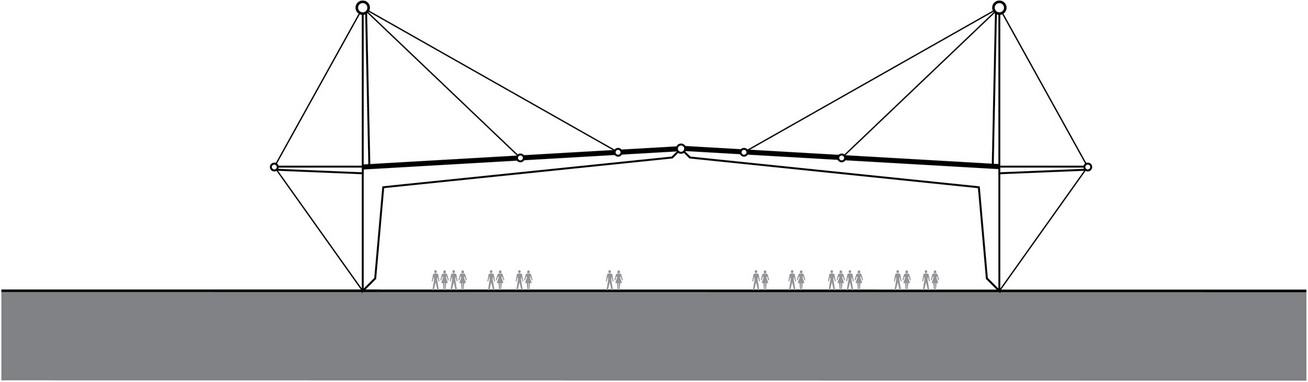
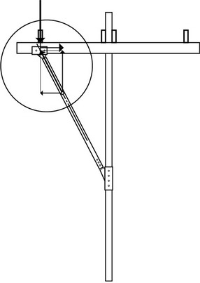
Inclined Columns
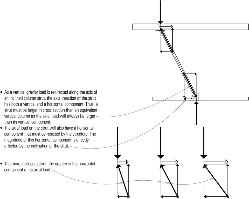
Columns may be inclined to transfer otherwise misaligned concentrated loads. An important secondary effect of inclining a column is the introduction of a horizontal component of the axial load into the supporting beam, floor slab, or footing, which must be incorporated into the design of these elements.
- Inclined columns can be designed as vertical columns while taking into account the additional moments resulting from the column’s self weight and the additional shear forces due to its inclination.
- Only the vertical component of the strut’s reaction can resist the gravity load.
Struts
While inclined columns that carry gravity loads are often referred to as struts, struts can refer to any inclined member subjected to compressive or tensile loads along its length, such as a component connected at its ends to other members of a trussed framework to maintain the rigidity of the structure. Struts fail primarily due to elastic buckling but are capable of resisting tension as well.
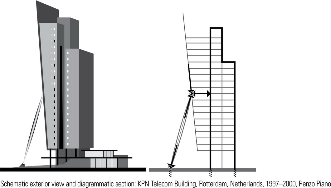
The examples on this page illustrate the various scales at which inclined columns can be used. The KPN Telecom Building is composed of three sections—a central vertical core and two adjacent towers. The second tallest section has a 5.9° incline, similar to the cables of the nearby Erasmus bridge. A glass curtain wall covers the inclined face and functions as a billboard using 896 specially manufactured lights. A distinctive feature is a 164-foot (50-m) inclined steel column, shaped like an elongated cigar, which is attached to the center point of the facade to assist in stabilizing the tower against lateral forces. If for some reason the inclined column were to be damaged, the building would not collapse.
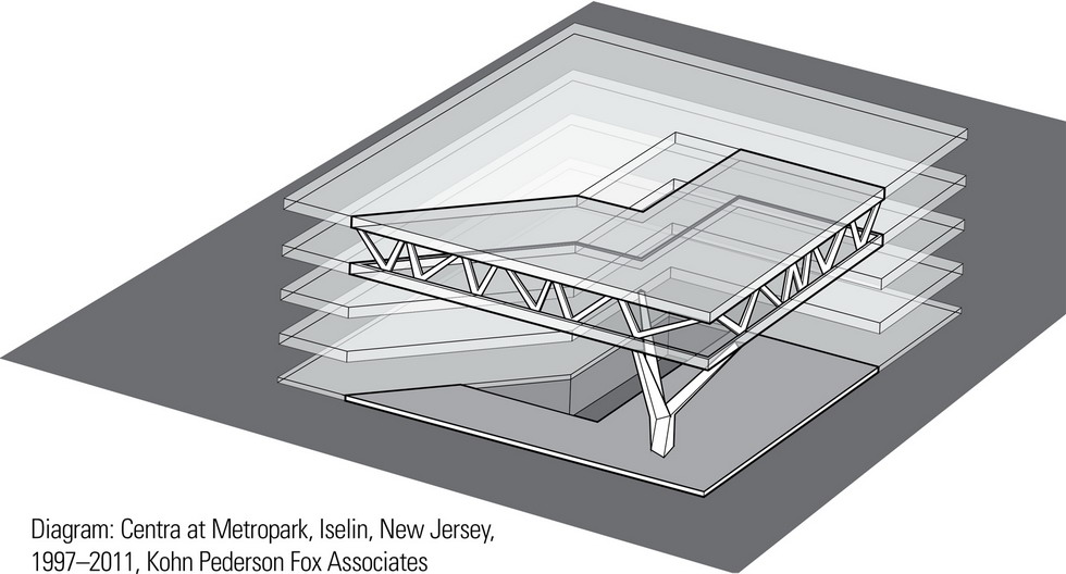
Centra at Metropark employs an asymmetrical tree column and full floor-to-ceiling trusses, 20 feet (6 m) deep and spanning 120 feet (36 m), to support a large overhang of the fourth floor. The fourth floor is suspended from the roof structure, enabling a rectangular opening in the center to be created to allow light to enter the plaza area below. The tree column was prefabricated in four sections out of thick steel plates, which were then welded together on site and injected with concrete.
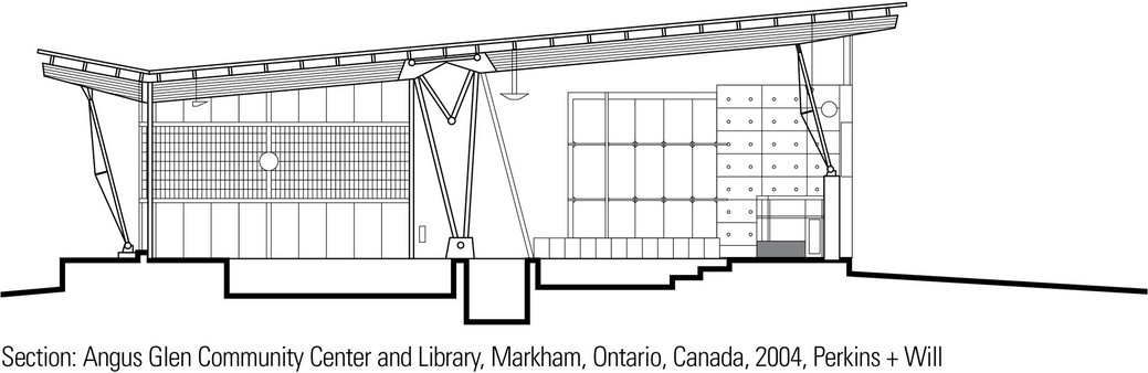
The roof of the Angus Glen Community Center and Library relies on a primary truss that spans the length of the swimming pool. Designed as a tension arch constructed of hollow tubular steel members without diagonals, the truss supports major glue-laminated beams and decking. Inclined columns support the truss only at its ends; there are no interior columns to create physical barriers in the space. Inclined trussed columns are also used to support the exterior ends of the glue-laminated beams.
Concrete columns are designed to act together with vertical and lateral reinforcement in resisting applied forces.
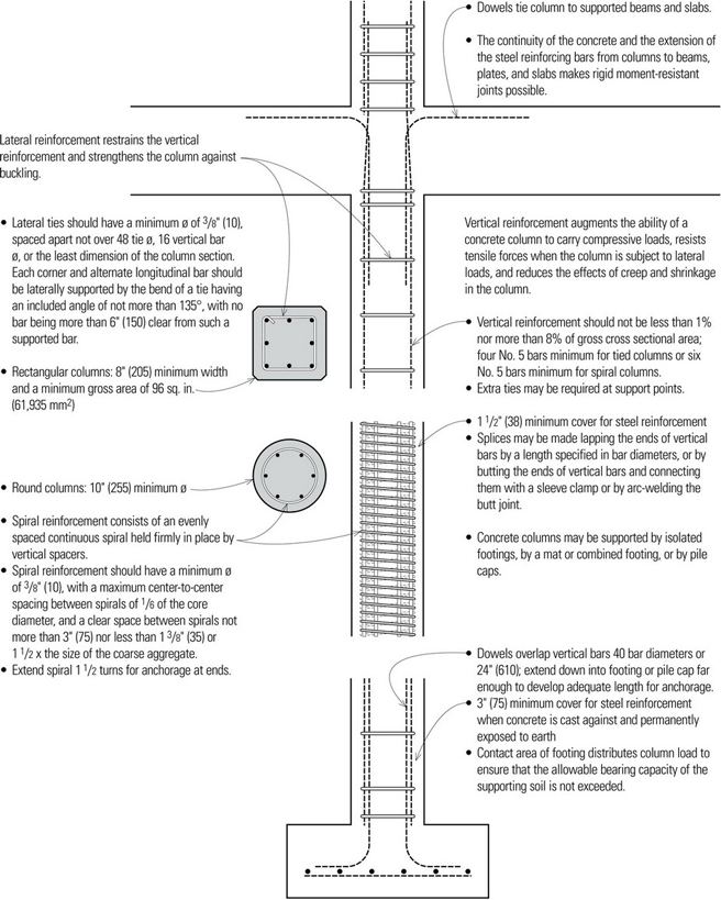
Reinforced concrete columns are usually cast with concrete beams and slabs to form a monolithic frame structure.
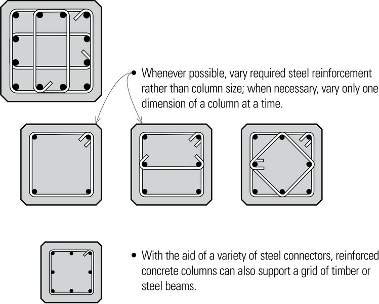
- Lay out columns along a regular grid for economical forming of beams and slabs.
- Columns should be continuous to the building foundation.
The following estimates for preliminary design assume a 12′ (3.6 m) height.
- 12″ column can support up to 2000 sf (185 m2) of floor and roof area.
- 16″ column can support up to 3000 sf (280 m2) of floor and roof area.
- 20″ column can support up to 4000 sf (372 m2) of floor and roof area.
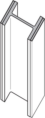
The most frequently used steel section for columns is the wide-flange (W) shape. It is suitable for connections to beams in two directions, and all of its surfaces are accessible for making bolted or welded connections. Other steel shapes used for columns are round pipes and square or rectangular tubing. Column sections may also be fabricated from a number of shapes or plates to fit the desired end use of a column.
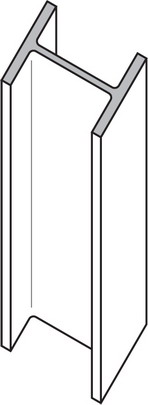
- W shape
- W shape w/ cover plates
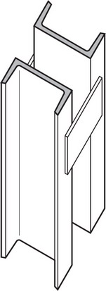
- Spaced channels
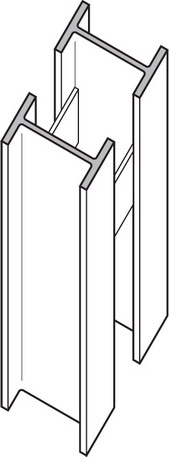
- Spaced W shapes
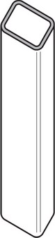
- Rectangular or square tubing

- Round pipes
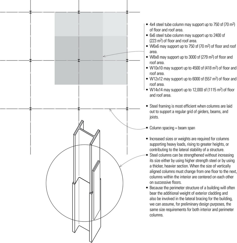
- Orient the webs of columns parallel to the short axis of the structural frame or the direction along which the structure is most susceptible to lateral forces.
- Orient the flanges on perimeter columns to the outside to facilitate the attachment of curtain walls to the structural frame.
- Resistance to lateral wind and seismic forces requires the use of shear planes, diagonal bracing, or rigid framing with moment-resisting connections.
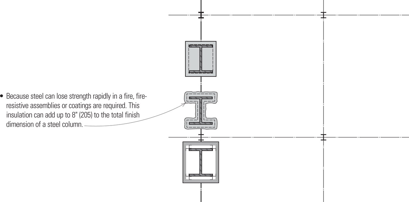
- In some construction types, structural steel may be left exposed if the building is protected by an automatic sprinkler system.
The allowable load on a steel column depends on its cross sectional area and its slenderness ratio (L/r), where (L) is the unsupported length of the column in inches and (r) is the least radius of gyration for the cross section of the column.
The following estimating guidelines for steel columns assumes an effective length of 12′ (3.7 m).
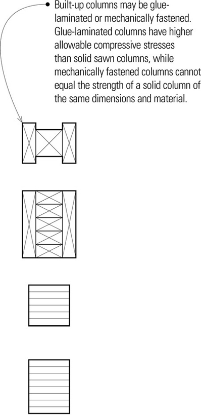
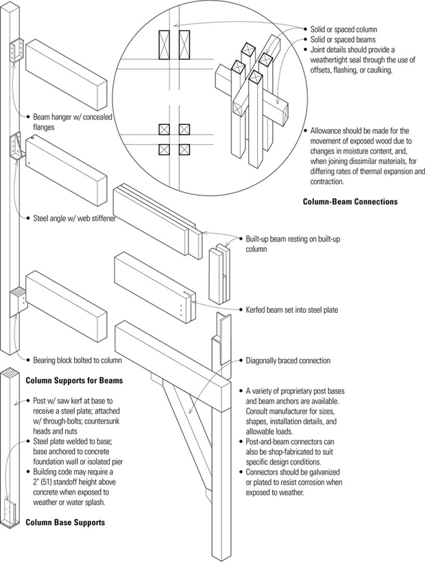
Wood Columns
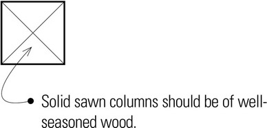
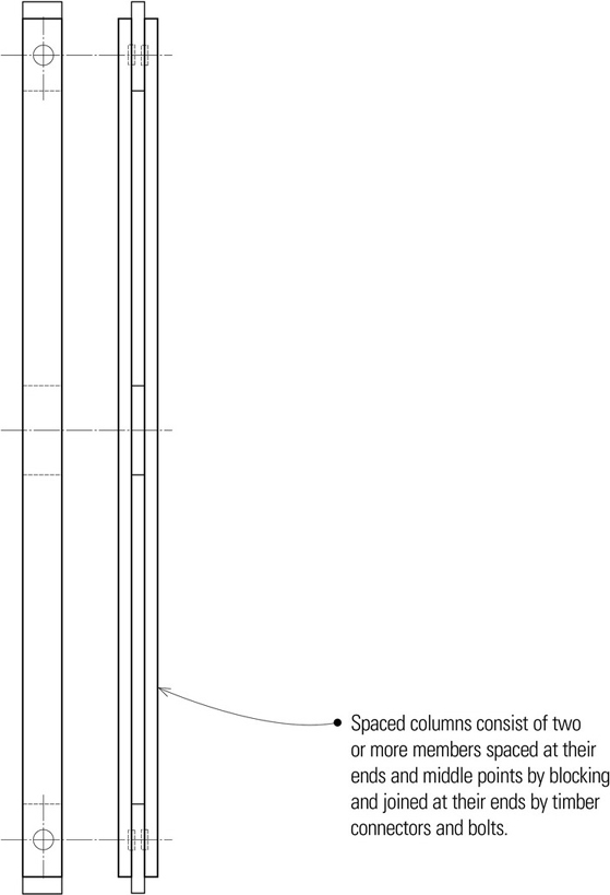
Wood columns may be solid, built-up, or spaced. In selecting a wood column, the following should be considered: lumber species; structural grade; modulus of elasticity; and allowable compressive, bending, and shear stress values permitted for the intended use. In addition, attention should be paid to the precise loading conditions and the types of connections used. The lack of old-growth lumber has reduced the availability of the higher structural grades of solid lumber, placing greater reliance on manufactured glue-laminated and parallel-strand-laminated (PSL) lumber for larger member sizes and higher structural grades.
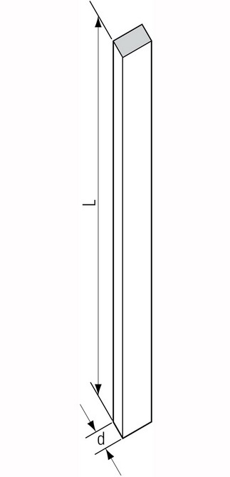
Wood columns and posts are loaded axially in compression. Failure can result from crushing of the wood fibers if the maximum unit stress exceeds the allowable unit stress in compression parallel to the grain. The load capacity of a column is also determined by its slenderness ratio. As the slenderness ratio of a column increases, a column can fail from buckling.
- L/d < 50 for solid or built-up columns
- L/d < 80 for individual member of a spaced column
- L = unsupported length in inches
- d = the least dimension of the compression member in inches
The following are estimating guidelines for wood columns.
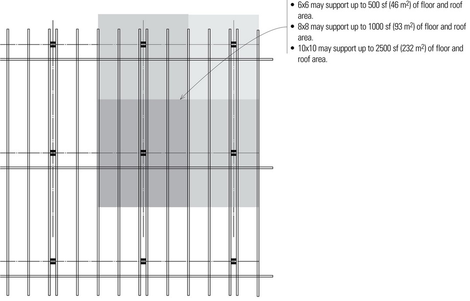
- Columns are assumed to have an unsupported height of 12′ (3.6 m).
- Increased sizes are required for columns supporting heavy loads, rising to greater heights, or resisting lateral forces.
- In addition to selecting a larger cross section, the capacity of a wood column can be increased by using a species with a greater modulus of elasticity or allowable stress in compression parallel to the wood grain.
Timber Connectors
If there is insufficient surface contact area to accommodate the required number of bolts, timber connectors can be used. Timber connectors are metal rings, plates, or grids for transferring shear between the faces of two timber members, used with a single bolt that serves to restrain and clamp the assembly together. Timber connectors are more efficient than bolts or lag screws used alone because they enlarge the area of wood over which a load is distributed and develop lower stresses.
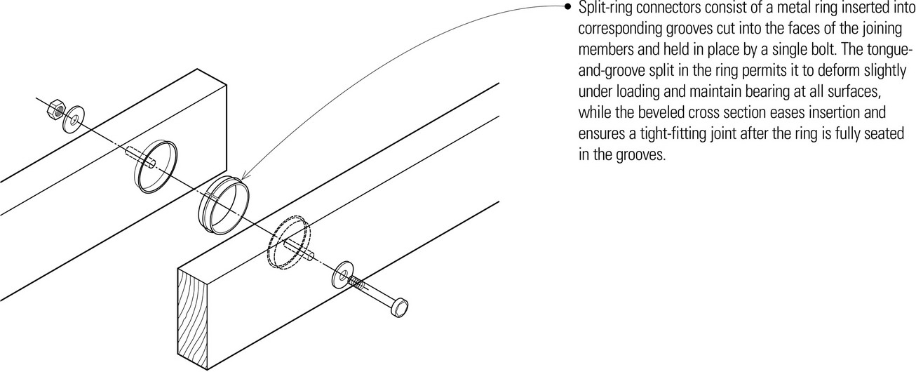
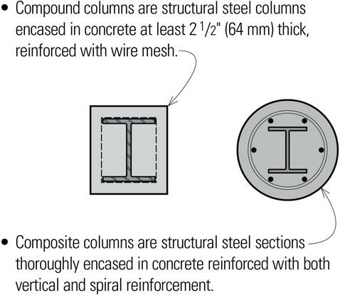
- Available in 2 ½″ and 4″ (64 and 100) diameters
- 3 ⅝″ (90) minimum face width for 2 ½″ (64) split rings; 5 ½″ (140) minimum for 4″ (100) split rings
- ½″ (13) ø bolt for 2 ½″ (64) split rings; ¾″ (19) ø for 4″ (100) split rings
- Shear plates consist of a round plate of malleable iron inserted into a corresponding groove, flush with the face of a timber, and held in place by a single bolt. Shear plates are used in back-to-back pairs to develop shear resistance in demountable wood-to-wood connections, or singly in a wood-to-metal connection.
Bearing Walls
A bearing wall is any wall construction capable of supporting an imposed load, as from a floor or roof of a building, and transmitting the compressive forces through the plane of the wall down to the foundation. Bearing wall systems can be constructed of masonry, cast-in-place concrete, site-cast tilt-up concrete, or wood or metal studs.
Bearing walls should be continuous from floor to floor and be aligned vertically from the roof to the foundation. Because of this continuity, bearing walls can act as shear walls and provide lateral resistance against earthquake or wind forces acting parallel to the plane of the walls. However, due to their relative thinness, bearing walls are unable to provide significant shear resistance to lateral forces acting perpendicular to their plane.
In addition to resisting the crushing or buckling from gravity loads, exterior bearing walls are subject to bending from horizontal wind loads. These forces are transferred to horizontal roof and floor planes and then to lateral force-resisting elements acting perpendicular to the bearing walls.
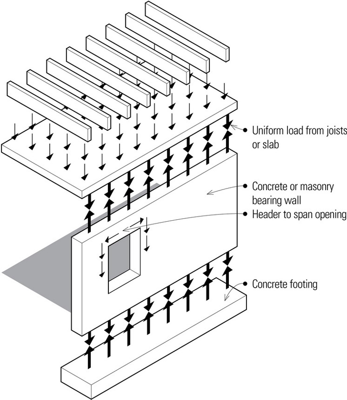
- Concrete slabs and roof or floor joists impose a uniformly distributed load along the top of a bearing wall. If there are no openings to disrupt the load path from the top of the wall, a uniform load will result on the top of the footing.
- Vertical loads must be redirected to either side of openings through the use of header beams in light-frame construction; arches or lintels in masonry construction; or additional reinforcing steel in concrete construction.
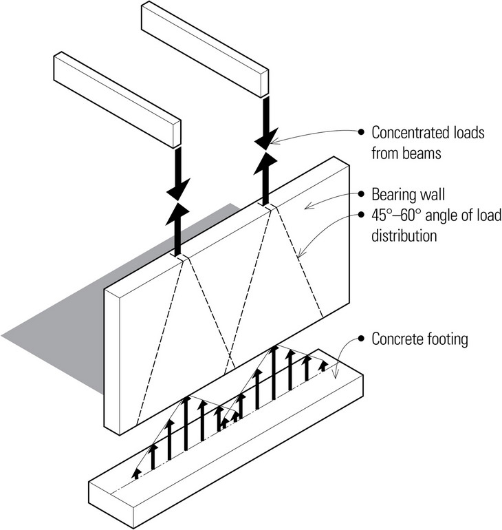
- Concentrated loads develop at the top of a wall when the columns or beams they support are spaced at wide intervals. Depending on the wall material, the concentrated load is distributed along an angle of 45º to 60º as it moves down the wall. The resulting footing load will be nonuniform, with the largest forces directly under the applied load.
- Building codes specify the required fire-resistance of exterior walls based on location, type of construction, and occupancy. Often walls meeting these requirements are also appropriate as bearing walls.
WALLS
Concrete Walls
Concrete walls may be precast, either on-site or off-site; more often, they are cast in place. The advantage of precast walls is in the high quality of concrete finishes that can be achieved and the fact that they can be prestressed. Typically, precast panels are used when the concrete wall will provide the finish wall surfaces. Precast wall panels are particularly appropriate for low-rise buildings that are not subject to high lateral loads.
- Site-cast concrete walls may be used as the primary vertical loadbearing elements of a structure or in conjunction with steel or concrete frames.
- The high fire resistance of concrete makes it an ideal material for enclosing building cores and shafts, and for serving as shear walls.
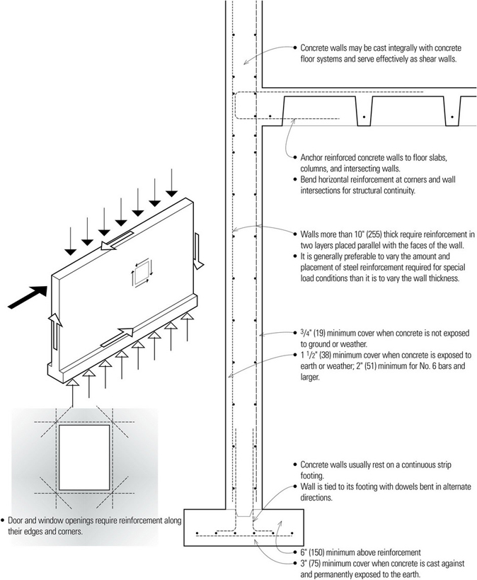
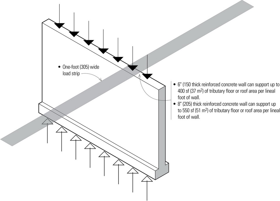
With the possible exception of multistory buildings, the bearing capacity of reinforced concrete walls typically will not be the critical factor in determining the thickness of the wall. Concrete walls must be supported laterally at regular intervals, both vertically and along their length. Intersecting floors or roofs stabilize the height of concrete walls while perpendicular walls or pilasters stabilize their length.
Minimum Wall Thicknesses:
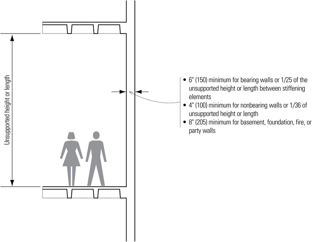
For multistory buildings and assuming a maximum height of 12′ (3.6 m) between floors:
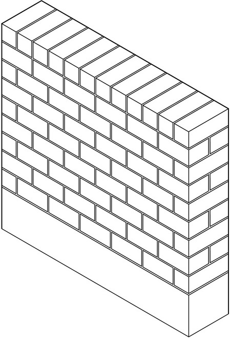
Masonry Walls
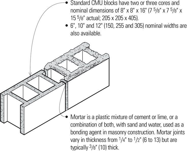
Masonry construction refers to building with units of various natural or manufactured products, such as stone, brick, or concrete block, usually with the use of mortar as a bonding agent to form walls that are durable, fire-resistant, and structurally efficient in compression. The most common structural masonry units are precast concrete masonry units (CMU) or concrete block. Because concrete block is more economical and easily reinforced, it has generally replaced fired clay brick and tile for bearing walls. Brick and clay tile are used primarily for their appearance as a finished surface, typically as a veneer on light frame or concrete block bearing walls.
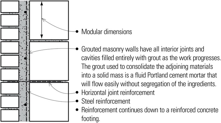
Masonry bearing walls may be constructed as solid walls, cavity walls, or veneered walls. While they can be constructed without reinforcing, masonry bearing walls should be reinforced in seismic zones by embedding steel reinforcing bars placed in thickened joints or cavities with a fluid grout mix of portland cement, aggregate, and water for greater strength in carrying vertical loads and increased resistance to buckling and lateral forces. It is essential that a strong bond develop between the reinforcing steel, grout, and masonry units.
- Exterior masonry walls must be weather-resistant and control heat flow.
- Water penetration must be controlled through the use of tooled joints, cavity spaces, flashing, and caulking.
- Cavity walls are preferred for their increased resistance to water penetration and improved thermal performance.
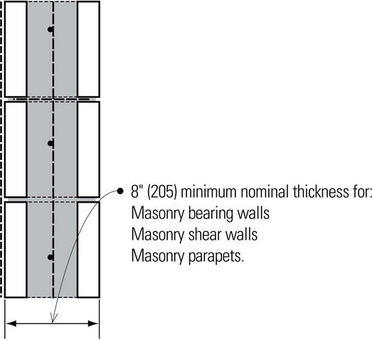
- 6″ (150) minimum nominal thickness for reinforced masonry bearing walls; masonry walls relied upon for resistance to lateral loading are limited to 35′ (10 m) in height.
- Masonry bearing walls are typically arranged in parallel sets to support steel, wood, or concrete spanning systems.
- Common spanning elements include open-web steel joists, timber or steel beams, and sitecast or precast concrete slabs.
- Masonry bearing walls must be laterally supported horizontally and vertically.
- Lateral support may be provided by cross walls, pilasters, or structural framing in the horizontal direction, and by floor or roof diaphragms in the vertical direction.
- Pilasters not only stiffen masonry walls against lateral forces and buckling, they can also provide support for large concentrated loads.
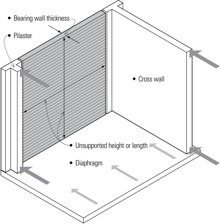
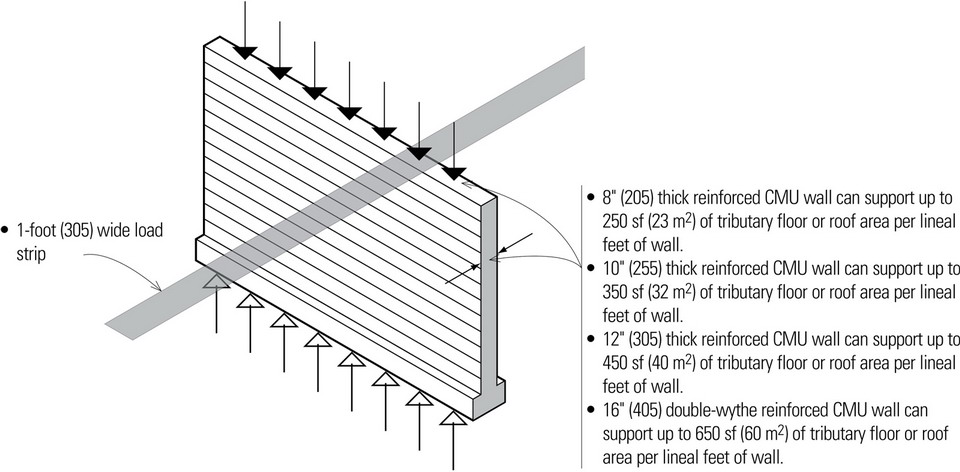
- A fully grouted bearing wall can have an unsupported height or length 20 times its thickness. All other masonry bearing walls can have an unsupported height or length up to 18 times its thickness.
- Differential movements in masonry walls due to changes in temperature or moisture content, or to stress concentrations, require the use of expansion and control joints.
Stud-Framed Walls
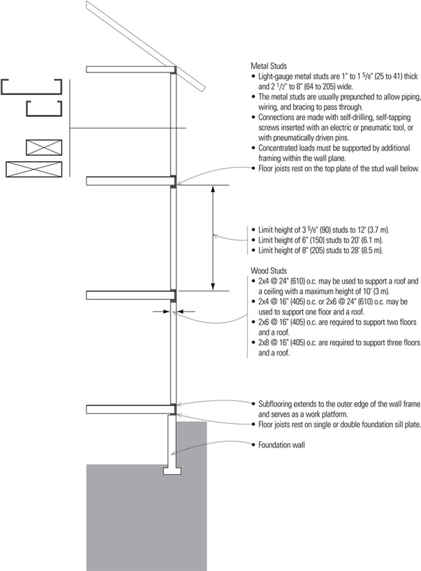
Light frame walls are constructed of light-gauge metal or wood studs that are typically spaced 12″, 16″, or 24″ (305, 405, or 610) on center, depending on the desired wall height and the size and spanning capability of common sheathing and surfacing materials. Light frame construction is typically used for bearing walls in low-rise structures that take advantage of the lightweight components and ease of assembly. The system is particularly well suited for buildings that are irregular in form or layout.
Light-gauge metal studs are manufactured by cold-forming sheet or strip steel. The cold-formed metal studs can be easily cut and assembled with simple tools into a wall structure that is lightweight, noncombustible, and dampproof. Metal stud walls may be used as nonloadbearing partitions or as bearing walls supporting light-gauge steel joists. Unlike wood light framing, metal light framing can be used for fabricating partitions in noncombustible construction. However, the fire-resistance rating of both wood and metal light frame wall assemblies is based on the fire resistance of the surfacing materials.
Both metal and wood stud walls can be idealized as monolithic walls when loaded uniformly from above. The studs carry the vertical and horizontal bending loads while the sheathing stiffens the plane of the wall and distributes both horizontal and vertical loads between individual studs. Any opening in the wall framing requires the use of header beams that redirect the loads to either side of the openings. Concentrated loads from the header reactions must be supported by a build-up of studs resembling a column.
Platform Framing
Platform framing is a light wood frame having studs only one story high, regardless of the stories built, with each story resting on the top plates of the story below or on the sill plates of the foundation wall.
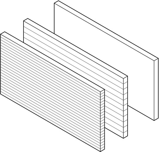
Curtain Walls
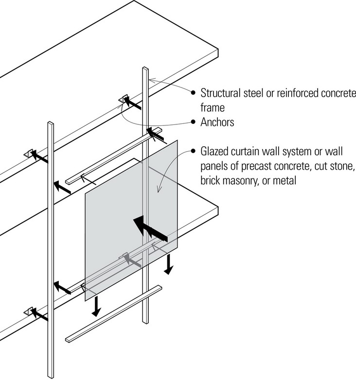
Curtain walls are exterior walls supported wholly by the steel or concrete structural frame of a building and carrying no loads other than their own weight and lateral loads. A curtain wall cannot contribute to the stability of the structure.
A curtain wall may consist of metal framing holding either vision glass or opaque spandrel units, or of thin veneer panels of precast concrete, cut stone, masonry, or metal. The wall units may be one, two, or three stories in height, and may be preglazed or glazed after installation. Panel systems offer controlled shop assembly and rapid erection, but are bulky to ship and handle.
While simple in theory, curtain wall construction is complex and requires careful development, testing, and erection. Close coordination is also required between the architect, structural engineer, contractor, and a fabricator who is experienced in curtain wall construction.
As with other exterior walls, a curtain wall must be able to withstand the following elements:
Loads and Wind
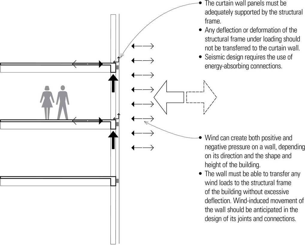
- Curtain walls must be capable of carrying their own weight as well as resisting lateral wind forces.
Sun
- Brightness and glare should be controlled with shading devices or the use of reflective or tinted glass.
- The ultraviolet rays of the sun can also cause deterioration of joint and glazing materials and fading of interior furnishings.
Temperature
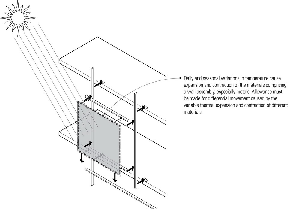
- Joints and sealants must be able to withstand the movement caused by thermal stresses.
- Heat flow through glazed curtain walls should be controlled by using insulating glass, insulating opaque panels, and by incorporating thermal breaks into metal frames.
- Thermal insulation of veneer panels may also be incorporated into the wall units, attached to their backsides, or provided with a backup wall constructed on site.
Water
- Rain can collect on the wall surface and be wind-driven under pressure through the smallest openings.
- Water vapor that condenses and collects within the wall must be drained to the outside.
- Pressure-equalized design principles become critical in the detailing of curtain walls, especially in larger and taller buildings, where the pressure differential between the outside atmosphere and an interior environment can cause rainwater to migrate through even the smallest openings in wall joints.
Fire
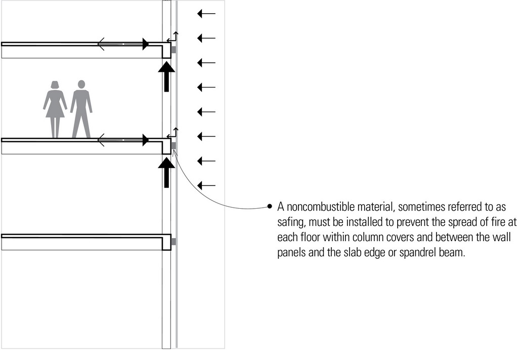
- The building code also specifies the fire-resistance requirements for the structural frame and the curtain wall panels themselves.
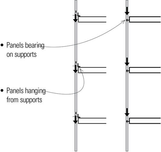
The curtain wall assembly must incorporate members that span either horizontally between columns or vertically between floors. While spanning horizontally from column to column is possible, the spans dictated by the column spacing of the structural frame are usually much greater than the floor-to-floor heights. For this reason, curtain wall systems typically span vertically from floor to floor and are suspended from steel or concrete spandrel beams or from the edge of cantilevered concrete slabs.
The primary spanning members of a curtain wall assembly may be aluminum extrusions, smaller steel channels and angles, or light-gauge metal framing. In panelized curtain walls, the spanning members form the strong-back that allows that panel to be handled as a unit.
If desired, secondary framing perpendicular to the primary spanning members can subdivide the module of the curtain wall design into smaller parts and incorporate a variety of devices that serve varying functions, such as opaque, insulated panels, operable windows for natural ventilation, and louvers or other sunscreening devices.
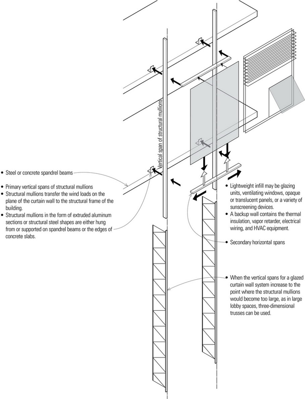
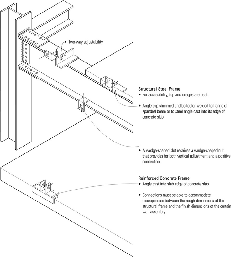
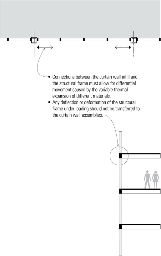
There are a variety of metal devices that may be used to secure a curtain wall to the structural frame of a building. Some connections are fixed to resist loads applied from any direction. Others are designed to resist only lateral wind loads. These joints typically permit adjustment in three dimensions in order to allow for discrepancies between the dimensions of the curtain wall units and the structural frame, as well as to accommodate the differential movement when the structural frame deflects under loading or when the curtain wall reacts to thermal stresses and changes in temperature.
Shim plates and angles with slotted holes allow adjustments to be made in one direction; a combination of angles and plates allows adjustments to be made in three dimensions. After final adjustments are made, the connections can be permanently secured by welding if a fixed connection is required.
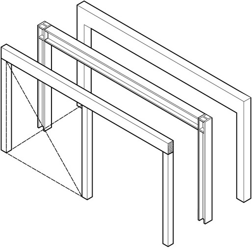
Relation of Curtain Wall to Structural Frame
The ability to separate the weather enclosure of the curtain wall from the structural function of the building frame leads to an important design decision—determining the position of the curtain wall in relation to the structural frame.
A curtain wall assembly can be related to the structural frame of a building in three fundamental ways:
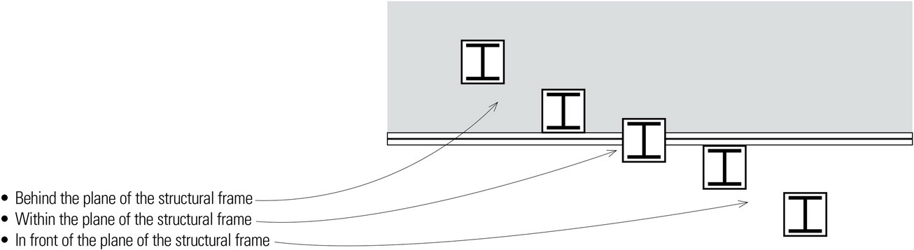
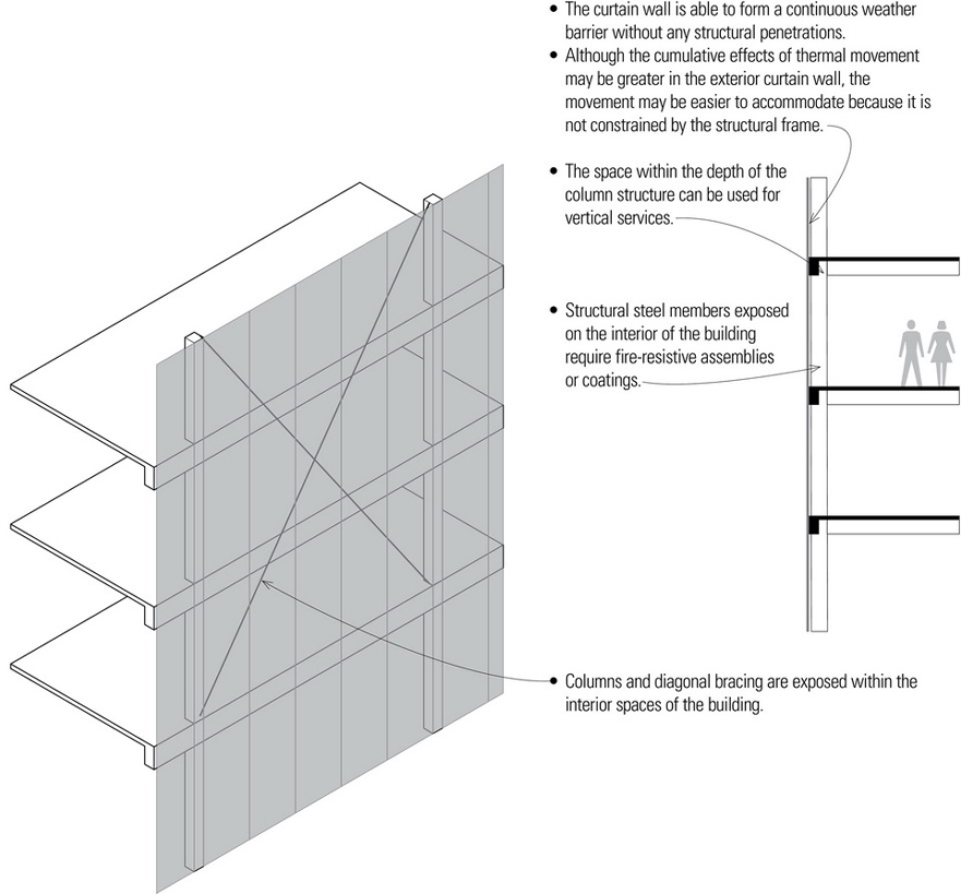
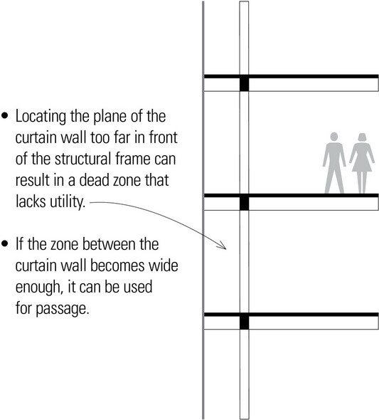
Curtain Walls in Front of the Structural Frame
The most common arrangement is to position the curtain wall assembly in front of the structural frame. Setting the plane of the curtain wall in this relation to the building structure allows the design of the exterior cladding to either emphasize the grid of the structural frame or offer a counterpoint to the pattern of columns and beams or slabs.
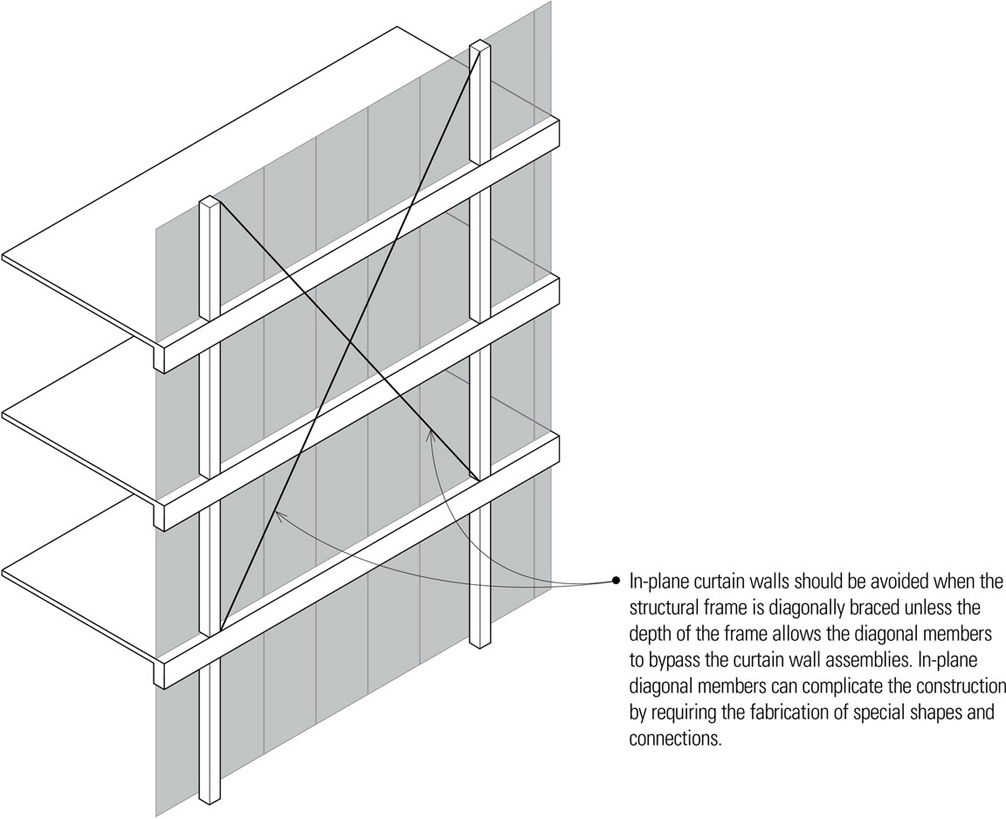
In-Plane Curtain Walls
Positioning the curtain wall panels or assemblies within the plane of the structural frame will express the scale, proportions, and visual weight of the column-and-beam frame in the building facade.
- The exposed columns and beams or slab edges may require weather-resistant cladding that incorporates a thermal barrier.
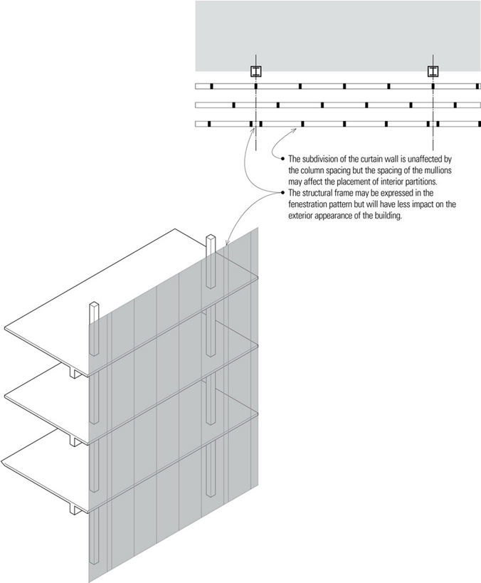
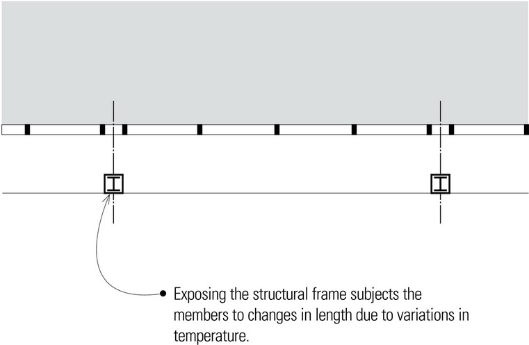
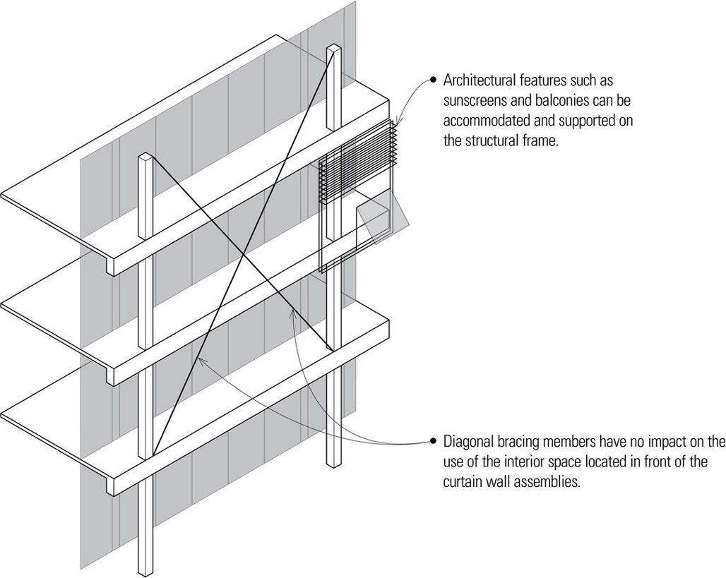
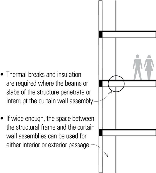
Curtain Walls Behind the Structural Frame
When the curtain wall is positioned behind the structural frame, the design of the structural frame becomes the major expressive feature of the exterior facade.
Structural Glass Facades
Curtain walls and structural glass facades are closely related but differ in their manner of support. Typically, curtain walls span from floor to floor, attached to and supported by the primary structure of a building. Aluminum extrusions are generally used as part of a framework that secures some type of panel material—glazing, composite metal, stone, or terra cotta.
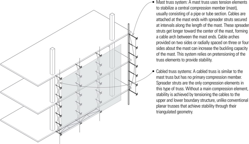
Structural glass facades have emerged over the past several decades as a means of providing maximum transparency in buildings. Structural glass facades integrate structure and cladding and can be used in long-span applications. The structural systems used to support the glazing are exposed and distinct from the building’s primary structure. Structural glass facades are generally categorized by the nature of the underlying support structure.
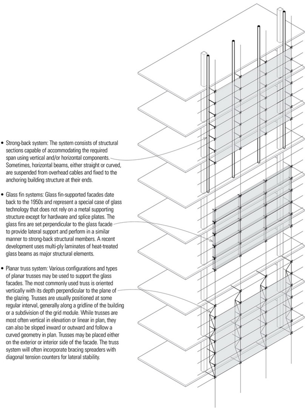
- Gridshells: Gridshells, a structural type pioneered in the 1940s by Frei Otto, are form-active structures that derive their strength from double-curved (synclastic or anticlastic) surface geometry. The system uses a network of in-plane prestressed cables to provide stability and shear resistance to the thin shell grid. Vaulted, domed, and other double-curved configurations can be used in vertical and overhead applications as well as to form complete building enclosures.
- Cable net systems: Cable nets represent one of the most recent developments in structural glass technology, minimizing the visible structural system and maximizing transparency. Horizontal and vertical cables yielding a net form are capable of spanning in two directions. The glass is supported by the net geometry of pretensioned cables. While the design of a cable net system can be flat, the nets are more often tensioned into double-curvature forms. Dual-function clamping components lock the cables together at their intersections as well as clamp the edges or corners of adjacent glass panes on the glazing grid.
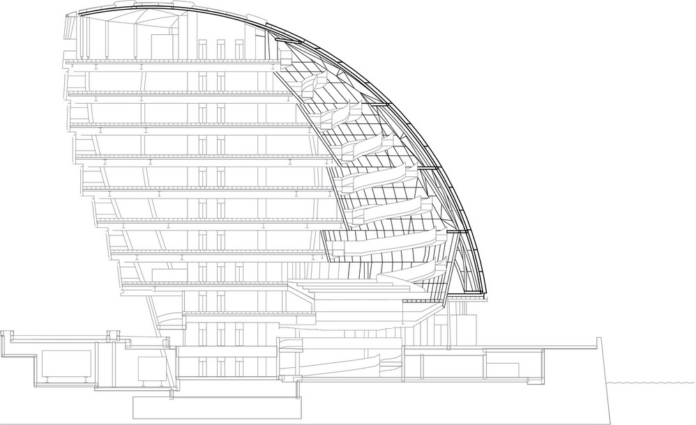
Section: London City Hall, London, England, 1998–2003, Foster + Partners
Diagrids
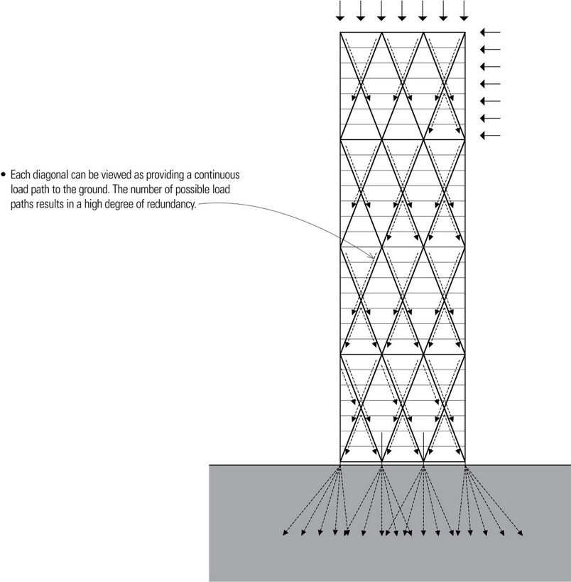
A diagrid refers to a structure of intersecting members that form a diagonal grid, connected at specially jointed nodes to create an integral network across a building surface capable of resisting lateral forces as well as gravity loads. This exoskeletal framework allows for the possible reduction of the number of internal supports, saving on space and building materials and providing for greater flexibility in interior layouts. Horizontal rings that tie all of the triangulated pieces together into a three-dimensional framework are necessary to provide buckling resistance to the exoskeletal grid.
- A diagrid pairs the structure of a continuous rigid shell, which resists loads in any direction, with the constructability afforded by the use of discrete elements.
- See also the discussion of diagrids and their application in stabilizing high-rise structures.
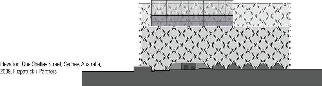
The One Shelley Street project uses a structural diagrid system to create a visually unique exterior. Because the diagrid is positioned on the outside of and very close to the glass facade, close monitoring, management, and coordination during fabrication and installation was required.
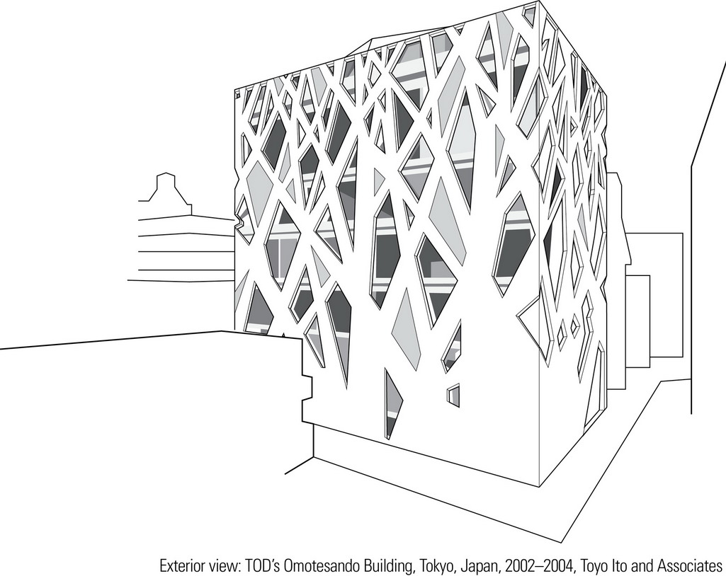
Unlike the geometric regularity of One Shelley Street’s diagrid, the concrete diagrid used in TOD’s Omotesando Building is based on a pattern of overlapping tree silhouettes that mimic the branch structure of nearby elm trees. Similar to the growth pattern of trees, the diagrid members get thinner and more numerous with a higher ratio of openings as you move up higher in the building. The resulting structure supports floor slabs spanning 32 to 50 feet (10 to 15 meters) without any internal columns. To minimize sway during an earthquake, the structure rests on a shock-absorbing foundation.
ROOF STRUCTURES
Roof structures, like floor structures, are horizontal spanning systems. However, while floor structures provide flat and level platforms for the support of our activities and furnishings, roof structures have a vertical aspect that can dramatically impact the exterior form of a building as well as the quality of the spatial volumes beneath their canopy. A roof structure may be flat or pitched, gabled or hipped, broad and sheltering, or rhythmically articulated. It may be exposed with edges flush with or overhanging the exterior walls, or it may be concealed from view, hidden behind a parapet. If its underside remains exposed, the roof also transmits its form to the upper boundaries of the interior spaces below.
Because the roof system functions as the primary sheltering element for the interior spaces of a building, its form and slope must be compatible with the type of roofing—shingles, tiles, or a continuous membrane—used to shed rainwater and melting snow to a system of drains, gutters, and downspouts. The construction of a roof should also control the passage of moisture vapor, the infiltration of air, and the flow of heat and solar radiation. Depending on the type of construction required by the building code, the roof structure and assembly may have to resist the spread of fire.
Like floor systems, a roof must be structured to span across space and carry its own weight as well as the weight of any attached equipment and accumulated rain and snow. Flat roofs used as decks are also subject to live occupancy loads. In addition to these gravity loads, the planes of the roof may be required to resist lateral wind and seismic forces, as well as uplifting wind forces, and transfer these forces to the supporting structure.
Because the gravity loads for a building originate with the roof system, its structural layout must correspond to that of the column and bearing wall systems through which its loads are transferred down to the foundation system. This pattern of roof supports and the extent of the roof spans, in turn, influences the layout of interior spaces and the type of ceiling that the roof structure may support. Long roof spans would open up a more flexible interior space while shorter roof spans might suggest more precisely defined spaces.
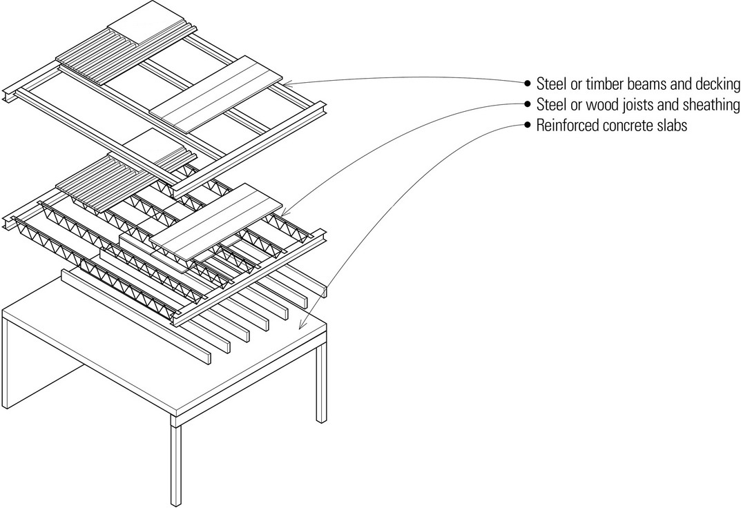
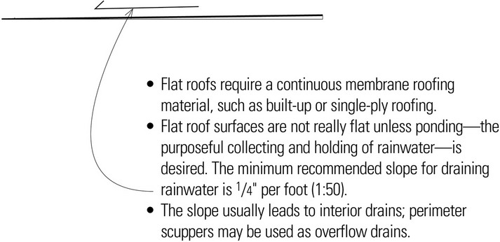
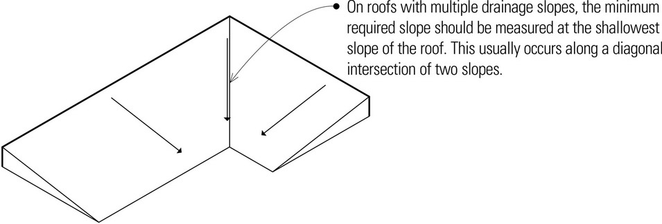
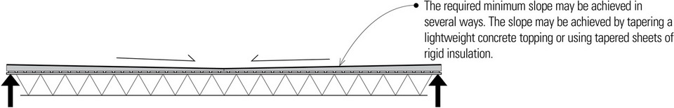
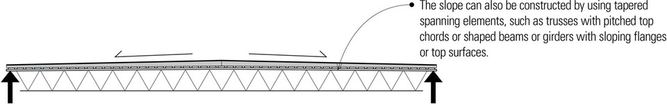
Flat Roofs
Flat roofs are analogous to floor structures in how they are structured and constructed. Their structure may consist of:
Sloping Roofs
The roof slope affects the choice of roofing material, the requirements for underlayment and eave flashing, and design wind loads. Some roofing materials are suitable for low-slope roofs; others must be laid over roof surfaces with steeper pitches to shed rainwater properly.
- Sloping roofs shed rainwater more easily to eave gutters more easily than flat roofs.
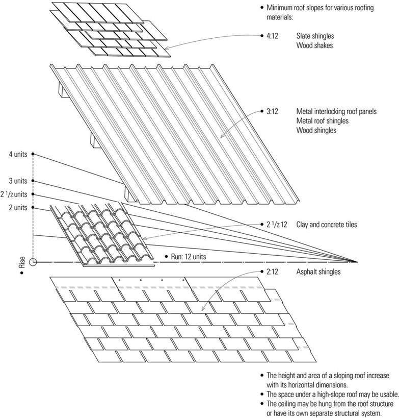
As with floor structures, the nature of the roofing material and the manner in which it is laid to shed rainwater determines the pattern of the secondary supports, which in turn dictates the direction and spacing of the primary spanning members of the roof structure. Understanding these relationships aids in developing the framing pattern for a roof structure.
- Roofing shingles, tiles, or panels may require either solid or spaced sheathing.
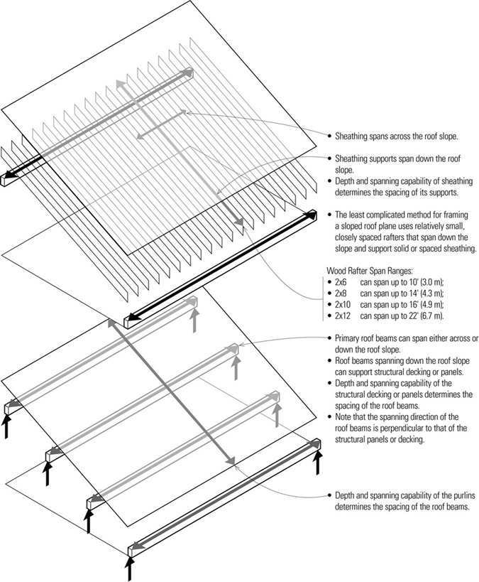
There are alternative ways in which to frame steel and timber roof structures, depending on the direction and spacing of the roof beams, the elements used to span the beam spacing, and the overall depth of the construction assembly.
Roof Beams Parallel with Slope
The steel or timber roof beams may be spaced 4′ to 8′ (1220 to 2440) o.c. and spanned with steel or wood decking. The beams may be supported by girders, columns, or a reinforced concrete or masonry bearing wall.
In a two-layer system, the roof beams may be spaced farther apart and support a series of purlins. These purlins, in turn, are spanned with roof decking or a rigid, sheet roofing material.
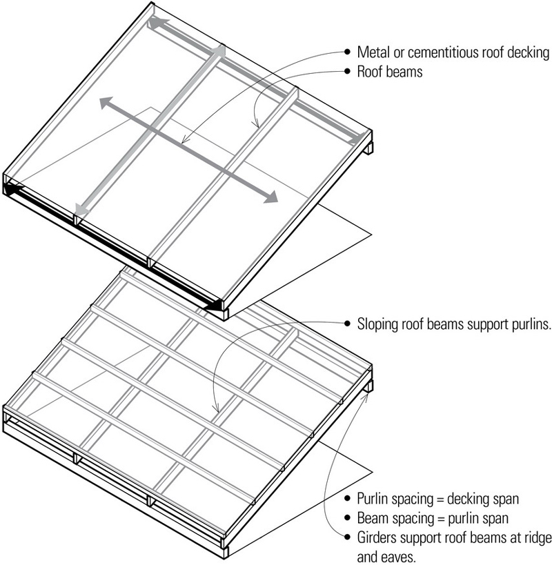
Roof Beams Perpendicular to Slope
In this example of a two-layer structure, the roof beams support a conventional system of rafters.
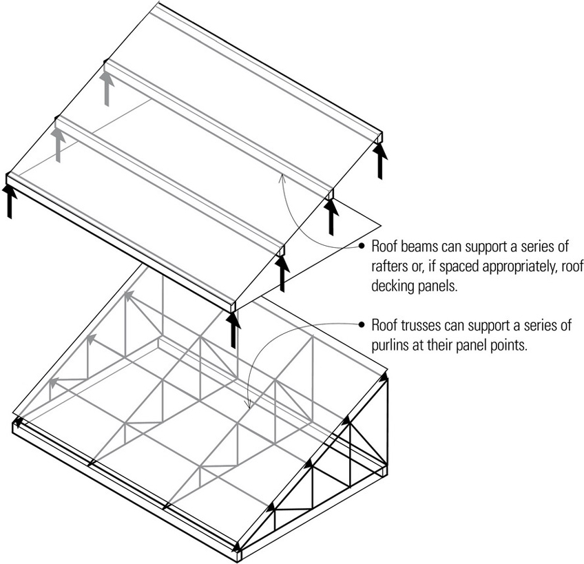
The roof beams may be spaced close enough to be spanned with roof decking. Spaced farther apart, the beams can support a series of secondary beams parallel with the slope.
When a series of shaped roof trusses is used in place of the primary roof beams, the lower chords and webs of the trusses will materially affect the quality of the space.
Multiple-Slope Roofs
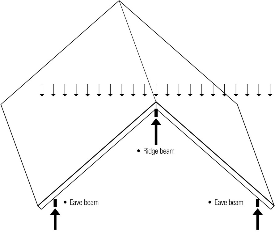
Sloping roof planes can be combined to create a variety of roof forms. One of the most common is the gable roof, consisting of two roof planes that slope downward from a central ridge.
There are two principal ways for framing a gable roof. A ridge beam supported by two or more columns can support a series of simple rafter spans.
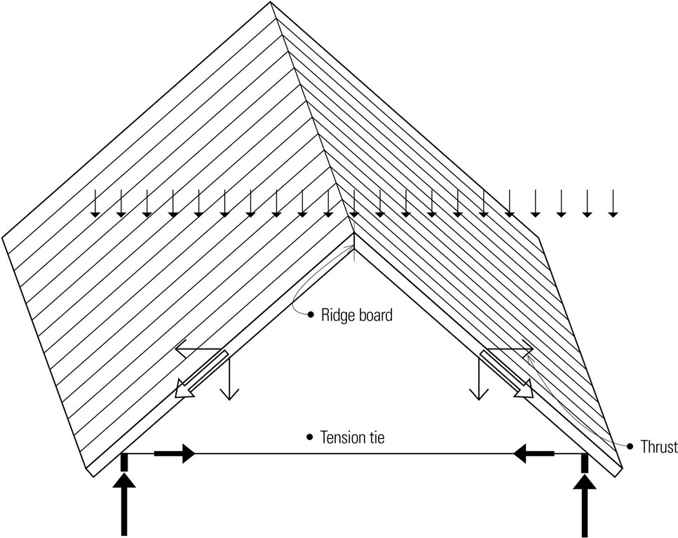
Alternatively, one series of rafters can rise and oppose the rafters rising from the other side, eliminating the need for a beam at the ridge. A ridge board is used instead simply to aid in aligning the rafters during construction. This method produces horizontal thrusts at the base of both sets of sloping rafters, which must be resisted by a tension tie connecting each pair of opposing rafters.
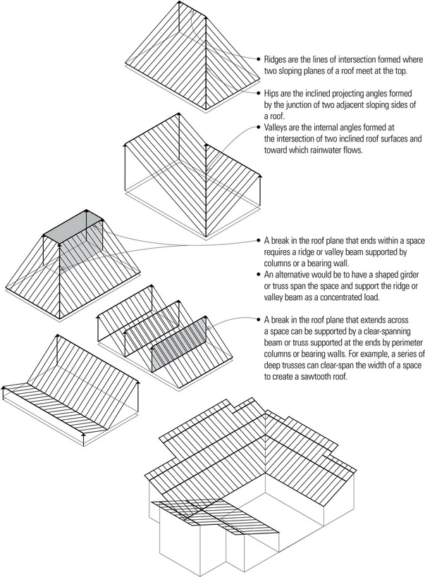
It is useful to think of any roof composition as a number of sloping planes that meet or intersect at either ridges, hips, or valleys, keeping in mind the resulting drainage pattern for shedding rainwater and melting snow. Ridges, hips, and valleys all represent breaks in a roof plane that require a line of support, which may be in the form of a beam or truss supported by columns or bearing walls.
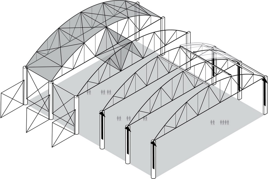
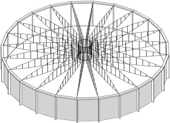
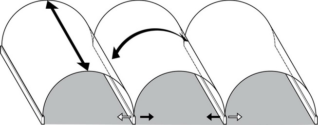
The spanning elements of hip roofs, domes, and similar roof forms can oppose and buttress each other at their peak. To counteract the horizontal thrust that results at their base supports, however, tension ties or rings, or a series of linked horizontal beams are required.
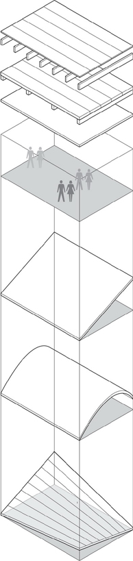
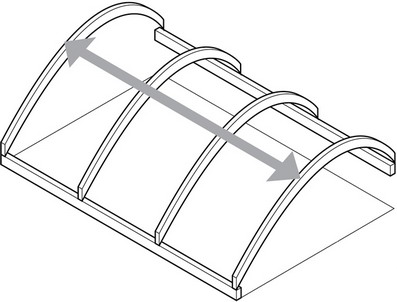
Vaulted Roofs
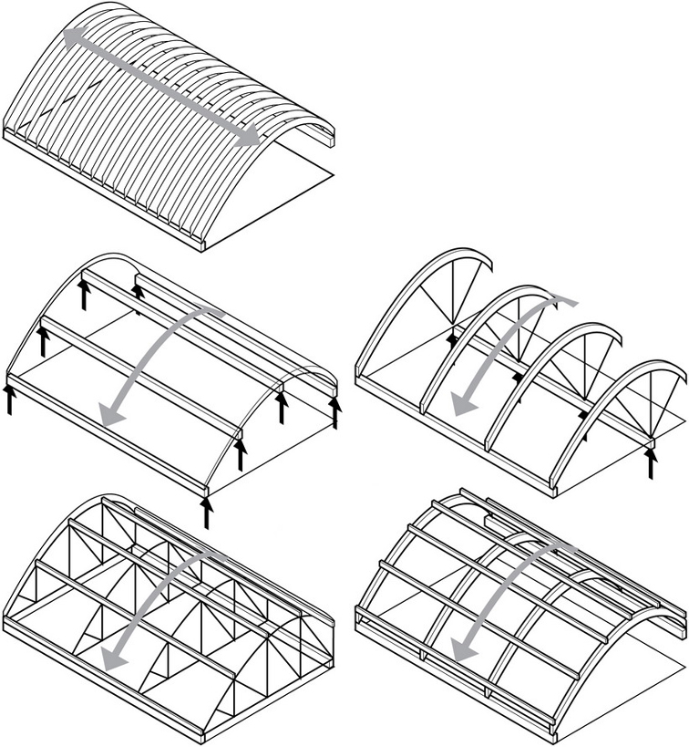
Curved roof surfaces may be structured by using spanning elements, such as built-up or custom-rolled steel beams, glue-laminated timber beams, or trusses that are shaped to match the desired profile of the form or space.
- Concrete slabs can also be formed to the desired curvature and extruded in the longitudinal direction. For example, a barrel shell can be extruded to behave as a deep beam with a curved section spanning in the longitudinal direction. If the barrel shell is relatively short, however, it exhibits archlike action and tie rods or transverse rigid frames are required to counteract the outward thrusts of the arching action.
- Shaped concrete members may be cast in place, but this would be economical only in situations where the spans are large and repetition minimal. For repetitive elements, precast concrete members are more economical. A shaped structural element is most efficient when its profile reflects the moment diagram for its span. For example, a section should be deeper where the bending moment is greater.
- When framing a curved roof with one-way spanning elements, the same considerations regarding roofing material and the direction of primary and secondary spans apply as they do for flat and sloping roofs.
As the scale of a structure increases, interior lines of support may become necessary to keep the roof spans within reasonable limits. Whenever possible, these lines of support should reinforce the spatial quality of the volumes being developed by the roof form. Where interior supports would interfere with the functioning of a space and clear spans are desirable, as in sports arenas and concert halls, long-spanning roof structures become necessary. For more information on long-span structures, see Chapter 6.