6
Long-Span Structures
LONG-SPAN STRUCTURES
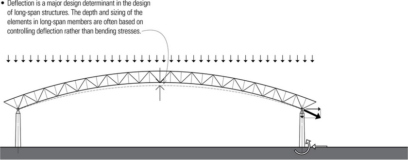
While span is a major problem in most large buildings, it dominates the design of auditoriums, exhibition halls, and similar facilities requiring a large expanse of column-free space. For buildings that have such requirements, designers and engineers have the task of selecting an appropriate structural system capable of resisting the large bending moments and deflections of long spans in as efficient a manner as possible without sacrificing safety.
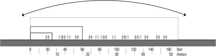
No specific definition exists for what constitutes a long-span structure. In this text, we are considering any span in excess of 60 feet (18 m) to be a long span. Long-span structures are used most often to shape and support the roofs of large, open floor spaces for a variety of building types, such as sports arenas, theaters, swimming centers, and airplane hangars. They can also be used to support the floors of buildings if a large space is embedded within a building structure.
- Stadiums used for football, baseball, or soccer may be either open or enclosed. Some enclosed stadiums have roof systems that shelter 50,000 to 80,000 spectators and have spans in excess of 800 feet (244 m).
- The size and shape of sports arenas are related to that of the central floor space and the configuration and capacity of the spectator seating area. The shape of the roof may be circular, oval, square, or rectangular, with critical spans generally in the range of 150 to 300 feet (45.7 to 91 m) or more. Almost all modern venues are column-free for unobstructed viewing.
- Theaters and performance halls are generally smaller than sports arenas but still require long-span roof systems to achieve column-free spaces.
- Exhibition and convention halls generally include a large space reserved for exhibits or consumer shows with floor area requirements ranging from 25,000 sf to more than 300,000 sf (2323 to 27,870 m2). Columns are spaced as far apart as feasible to provide maximum flexibility in layout. Although a column spacing of 20 to 35 feet (6.1 to 10.7 m) is used quite frequently for standard types of occupancies, exhibition halls may have a column spacing in excess of 100 feet (30 m) or more.
- Other building types that typically use long-span systems include warehouses, industrial and manufacturing facilities, airport terminals and hangars, and large retail stores.
Structural Issues
Scale plays a major role in the determination of structural form. For relatively small structures, such as a single-family residence or utility buildings, the structural requirements can be met through simple structural systems using a variety of materials. However, for very large structures, vertical gravity forces and lateral forces of wind and earthquakes often limit the structural materials that can be used, and the limitations of construction methods begin to dominate the concept of the structural system.
- Some long-span structures, such as domes and cable systems, are effective in supporting distributed loads but are sensitive to concentrated loads from heavy equipment.
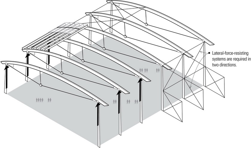
- Stabilizing long-span structures against lateral forces is especially critical because of the large occupancies they typically house.
- Long-span structures have little redundancy and are subject to catastrophic failure if a key element or elements fail. Columns, frames, and walls supporting long-span members have very large tributary loads, and little opportunity exists for a redistribution of these loads to other members if a localized failure occurs.
- Ponding is one of the most critical conditions in the design of long-span roofs. If a roof experiences deflection that prevents normal water runoff, additional water might collect in the middle of the span and cause even more deflection, which allows even more load to accumulate. This progressive cycle can continue until structural failure results. Roofs should be designed with sufficient slope or camber to ensure proper drainage or be designed to support maximum loads that include ponding.
Design Issues
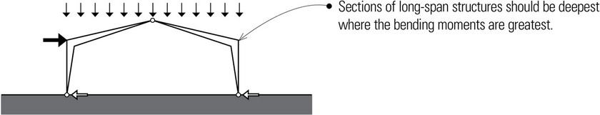
For economy and efficiency, long-span structures should be shaped according to an appropriate structural geometry. For example, their sections should be deepest where the largest bending moments occur and thinnest at pin joints where bending moments are at a minimum or nonexistent. The resulting profile can have a powerful impact on the exterior of a building, and in particular its roof profile, as well as on the form of the interior space they house.
The choice of an appropriate long-span structural system is a matter of the span range desired or required by the activities to be housed, the formal and spatial implications on the building design, and the economic factors related to material, fabrication, shipping, and erection. Any one of these factors may limit the possible choices of a long-span structure.
Another decision a designer faces is to what extent the long-span structure is expressed or even celebrated. Because of the large scale of long-span structures, it would be difficult to conceal their presence. Nevertheless, some long-span structures more clearly express how they soar across space while others are more muted in their structural role. Thus the decision can be made as to whether the building design exploits the structural mechanics of a long-span system or moderates its impact so that the focus is on the activities within a space.
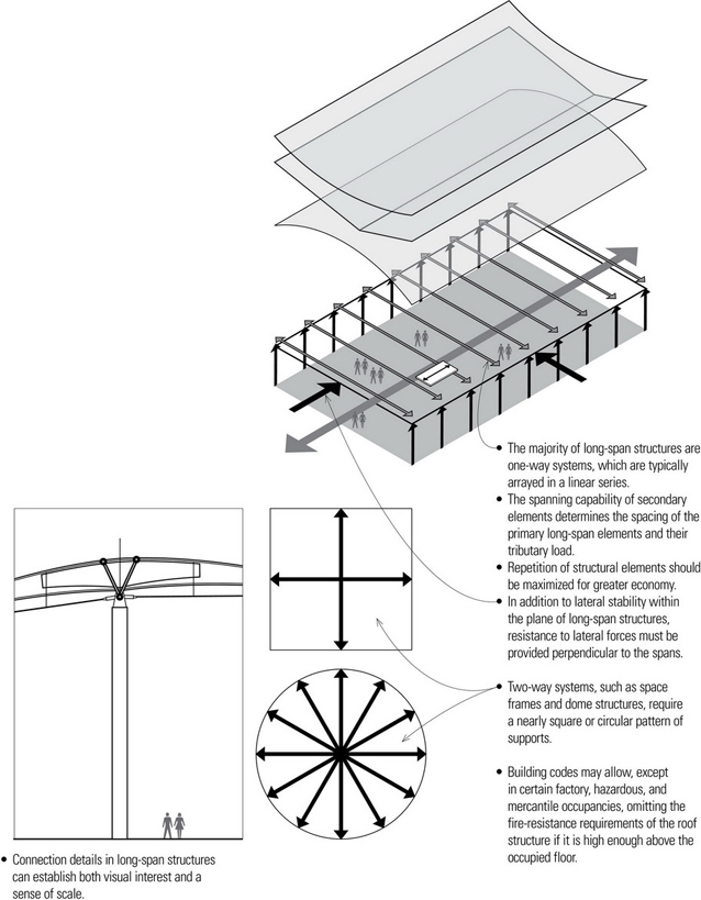
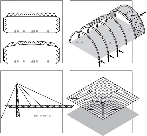
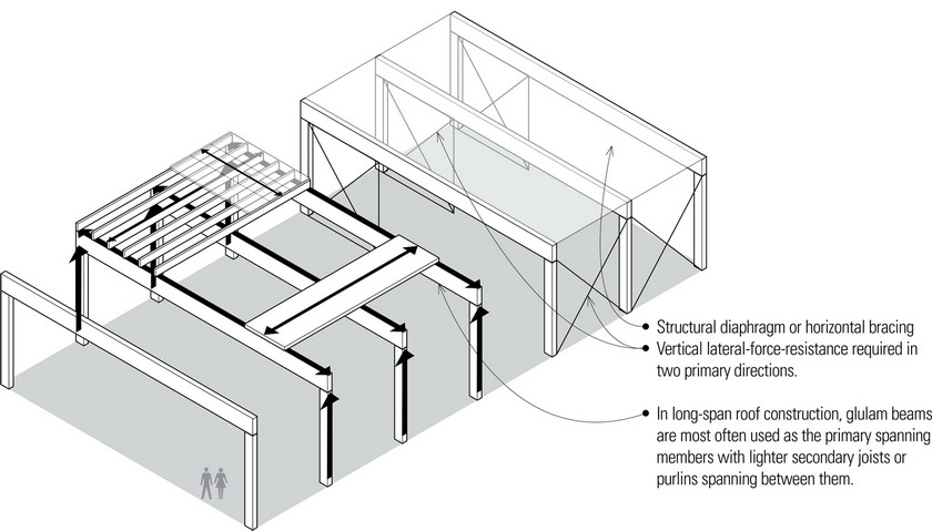
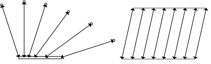
- Because the majority of long-span structures are one-way systems, their profile is an important design consideration.
- Flat beam and trussed structures permeate both exterior forms and interior spaces with a rectilinear geometry.
- Vaulted and domed structures give rise to convex exterior forms and concave interior spaces.
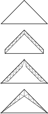
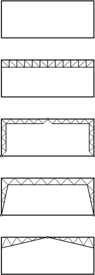
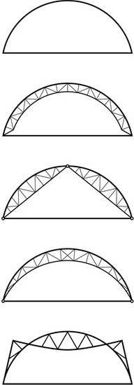
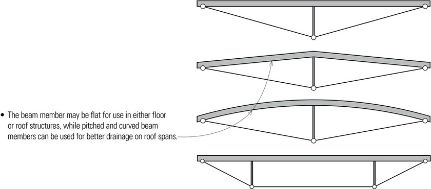
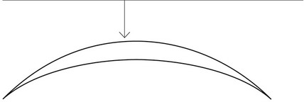
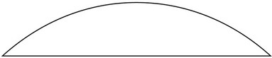
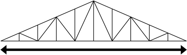
- Trussed, arched, and cable systems offer a variety of profiles. For example, illustrated here are a few of the many possible profiles for long-span trusses and trussed arches.
Construction Issues
- Long-span members are difficult to ship and require significant space for storage at the construction site. The maximum length is typically 60 feet (18.3 m) for truck transport and approximately 80 feet (24.4 m) for rail transport. The depth of long-span beams and trusses can also cause problems in shipping. The maximum width for highway transport is about 14 feet (4.3 m).
- Because of transport limitations, field assembly is generally required for long-span members. The assembly of long-span members normally occurs on the ground, before they are hoisted into place with a crane. The total weight of each long-span member is therefore a major consideration when specifying the capacity of the crane at the site.
ONE-WAY SYSTEMS
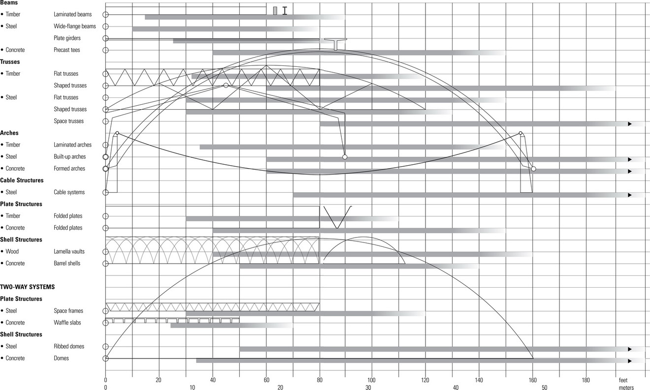
Listed in the table below are span ranges for the basic types of long-span structures.
LONG-SPAN BEAMS
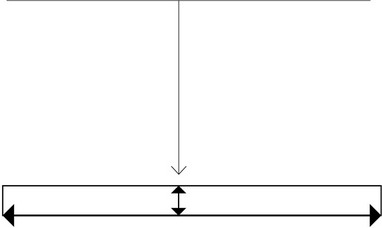
Flat beam structures are most appropriate when the minimum volume of space is required within the desired clear height. The achievable span is then directly related to the depth of the beams which, for normal loadings, would require a depth-to-span ratio of approximately 1:20 for glue-laminated beams and steel girders. Although solid web beam structures have a depth-to-span advantage, they have a high self-weight and do not easily accommodate mechanical services as do open-web or trussed beam structures.
Glue-Laminated Beams
Solid-sawn timber beams are not available for long spans but glue-laminated (glulam) timber beams are capable of spanning up to 80 feet (24.4 m). Glulam beams have superior strength and can be manufactured with large cross sections and curved or tapered profiles.
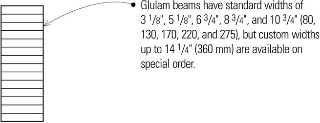
- Glulam beam depths range in multiples of 1 ⅜″ or 1 ½″ (35 or 38) laminations up to 75″ (1905). Curved members can be laminated in ¾″ (19) laminations to create tighter curvature.
- Because of their length, long-span glulam beams require special transport from the fabricating facility to the job site.
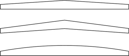
- Various profiles are available to allow for roof drainage.
- The cross sectional size of long-spanning glulam beams is large enough to qualify their use in Type IV or “heavy timber” construction, which is roughly the equivalent of one-hour fire-resistive construction.
Steel Beams
Wide-flange steel sections are capable of spanning up to 70 feet (21 m) with a depth of 44 inches (1120). Deeper sections for longer spans are possible by fabricating plate girders built up from steel plates and sections welded together to create the equivalent of a rolled beam.
Both plate girders and rolled wide-flange sections are not very efficient in long-span applications because the amount of material necessary to meet the bending and deflection requirements becomes excessive. It is often economical to vary the profile of the plate girder to provide the largest section for the maximum bending moment and reduce the section where the bending moment is low, thus reducing the beam’s dead load by removing material where it is not necessary. Such tapered profiles are especially useful in accommodating the drainage of rainwater on roof structures.
Concrete Beams
Conventional reinforced concrete members can be used to span long distances but in doing so, they become very large and bulky. Prestressing the concrete results in more efficient, smaller, and lighter cross sections that experience less cracking than standard reinforced concrete.
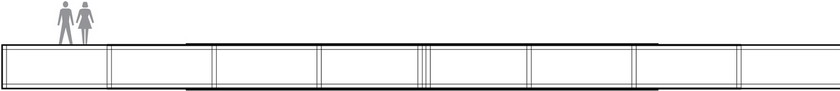
Concrete members may be prestressed by either pretensioning at a factory site or posttensioning at the construction site. Precast, pretensioned members require carefully planned handling and transport. An advantage of on-site posttensioning of a concrete beam or girder is the elimination of the transport of very long precast members to the job site.
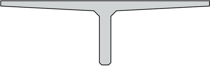
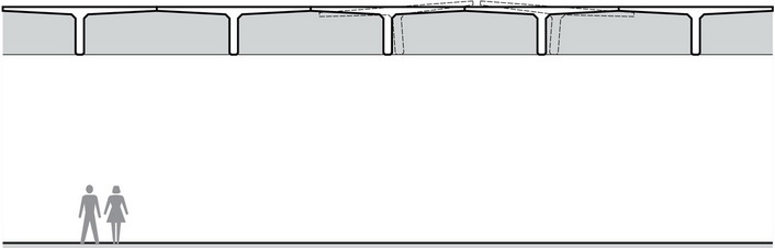
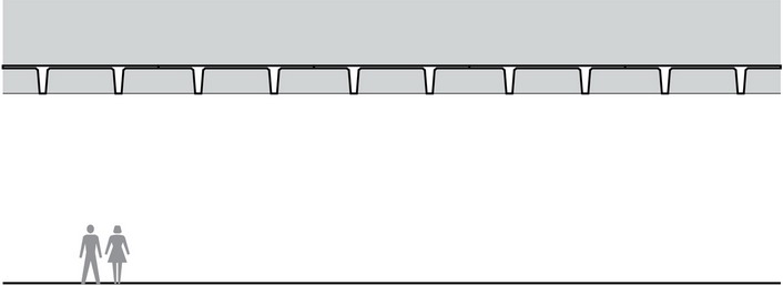
Precast, prestressed concrete members come in standard shapes and dimensions. The two most commonly used shapes are the single-tee and double-tee. Double-tees are commonly used for spans up to 70 feet (21 m) while single-tees are used for spans up to 100 feet (30 m) or more. Special shapes are also possible but are only economical when there is enough repetition to justify the cost of the specialized forms necessary for their casting.
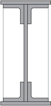
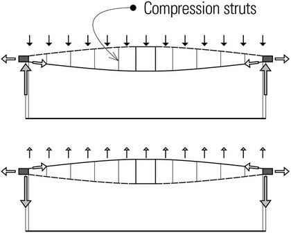
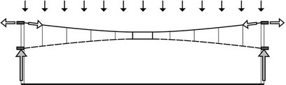
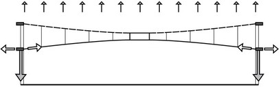
Trussed Beams
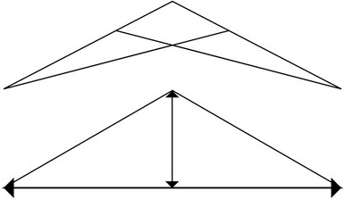
A trussed beam is a continuous beam stiffened by a combination of compression struts and diagonal tension rods. The vertical struts provide intermediate support points for the beam member, reducing its bending moments, while the resulting trussing action increases the load-carrying capacity of the beam.
- Trussed beams are an efficient and relatively economical way of increasing the load and span capability of glue-laminated and rolled steel beams.
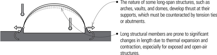
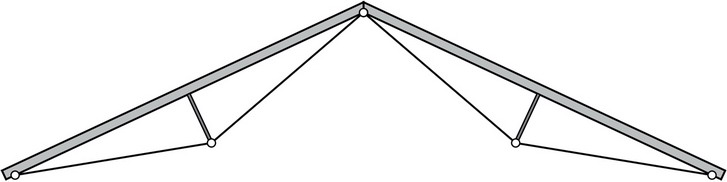
- Longer spans are possible when trussed beams are used in combination to form three-hinged arches. Because three-hinged arches (see page 256) develop horizontal thrust at each support, abutments or tension ties may be required for thrust resistance.
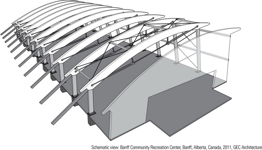
The roof of the Banff Community Recreation Center is supported by glue-laminated trussed arches salvaged from the old curling rink. Salvaged glue-laminated members were also used for columns throughout the complex. All salvaged members were inventoried, inspected, and tested to modern standards to determine the suitability of the members for reuse. In some cases, members were cut to create two smaller members.
LONG-SPAN TRUSSES
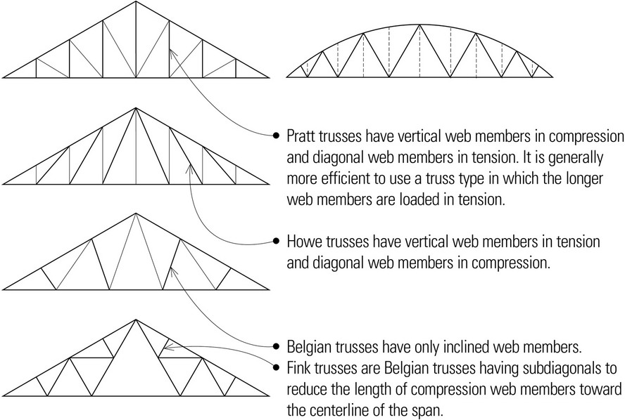
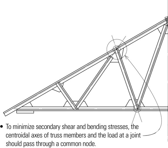
Trusses are pin-jointed and triangulated assemblies of simple struts stressed in either tension or compression. Truss bending moments are resolved into tension and compression forces in the bottom and top chords. Shear forces are resolved into tension and compression forces in the diagonal and vertical members.
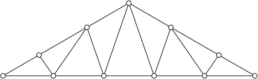
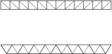
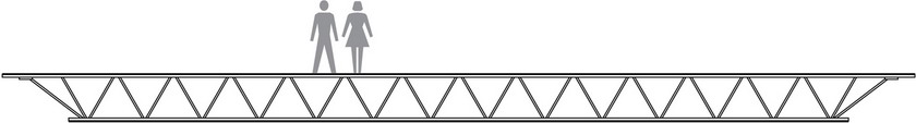
- Flat trusses have parallel top and bottom chords. Flat trusses are generally not as efficient as pitched or bowstring trusses.
- Span range for flat trusses: up to 120′ (37 m)
- Depth range for flat trusses: span/10 to span/15
- Scissors trusses have tension members extending from the foot of each top chord to an intermediate point on the opposite top chord.
- Span range for shaped trusses: up to 150′ (46 m)
- Depth range for shaped trusses: span/6 to span/10
- Crescent trusses have both top and bottom chords curving upward from a common point at each side.
- Bowstring trusses have a curved top chord meeting a straight bottom chord at each end.
- Warren trusses have inclined web members forming a series of equilateral triangles. Vertical web members are sometimes introduced to reduce the panel lengths of the top chord, which is in compression.
Trusses use material more economically and are more efficient in spanning long distances than solid beams but are relatively expensive to fabricate because of the number of connections and the complexity of the joints. They become more economical when spanning 100 feet (30 m) or more and when used as primary structural members supporting secondary trusses or beams.
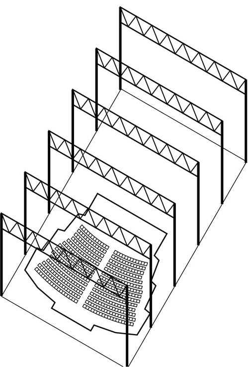
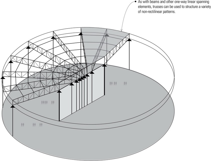
- Long-span trusses are used most often for roof structures and come in a multitude of profiles. When used occasionally for floors, the trusses have parallel chords.
- The spacing of major long-span trusses is a function of the spanning capability of the secondary framing elements running perpendicular to the truss span. Commonly used truss spacing ranges from 6 to 30 feet (1.8 to 9 m) on center.
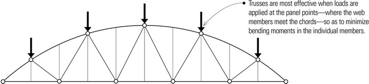
- The spacing of the secondary elements is controlled by the panel spacing of the major trusses to enable the load transfer to occur at those panel joints.
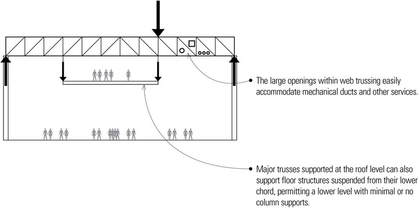
- Parallel-chord trusses are also useful in carrying large loads over a long span, as when columns are removed from a lower level and floor trusses transfer column loads from above to the truss supports. These major trusses are referred to as transfer trusses.
Trusses are generally constructed out of timber, steel, and sometimes a combination of timber and steel. Due to its weight, concrete is seldom used for trusses. The decision to use timber or steel depends on the desired appearance, compatibility with the roof framing and roofing materials, and the required type of construction.
Steel Trusses
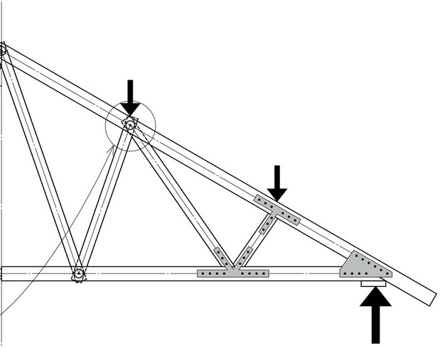
Steel trusses are generally fabricated by welding or bolting structural angles and tees together to form the triangulated framework. Because of the slenderness of these truss members, connections usually require the use of steel gusset plates. Heavier steel trusses may utilize wide-flange shapes and structural tubing.
- Members are bolted or welded with gusset plate connectors.
- Any knee bracing should also connect to the top or bottom chord at a panel point.
- The cross sectional size of compression members, being governed by buckling, is larger than that of tension members, which is controlled by tensile stresses. It is better to place shorter truss members in compression and longer ones in tension.
Wood Trusses
In contrast to monoplanar trussed rafters, heavier wood trusses can be assembled by layering multiple members and joining them at the panel points with split-ring connectors. These wood trusses are capable of carrying greater loads than trussed rafters and are therefore spaced farther apart.
- Solid wood members may be joined with steel plate connectors.
- Composite trusses have timber compression members and steel tension members.
- Member sizes and joint details are determined by engineering calculations based on truss type, load pattern, span, and grade and species of lumber used.
Open-Web Joists
- Commercially manufactured open-web timber and steel joists are much lighter than regular trusses and are capable of spans up to 120 feet (37 m).
- Composite open-web joists have top and bottom wood chords and a web of diagonal steel tubing. Composite joists suitable for spans in excess of 60 feet (18.3 m) have depths from 32″ to 46″ (810 to 1170). Heavier weight composite joists range in depth from 36″ to 60″ (915 to 1525).
- The LH and DLH series of open-web steel joists are suitable for long-span applications. The LH series are suitable for the direct support of both floors and roof decks while the DLH series are suitable only for the direct support of roof decks.
- LH series joists have depths from 32″ to 48″ (810 to 1220) for spans in the 60- to 100-foot (18- to 30-m) range. The DLH-series ranges in depth from 52″ to 72″ (1320 to 1830) with spanning capabilities in the 60- to 140-foot (18.3- to 42.7-m) range.
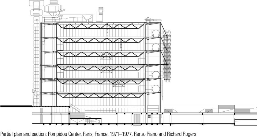
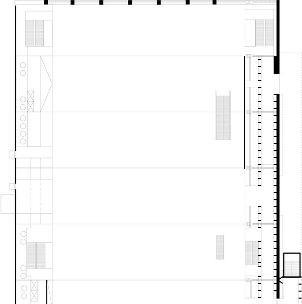
The major steel trusses of the Pompidou Center are spaced at 42-foot (12-m) intervals and span approximately 157 feet (48 m). On top of the supporting columns at each level are custom molded steel hangers, each measuring 26 feet (8 m) in length and weighing 20,000 pounds. Composite concrete and steel wide-flange beams span the major trusses.
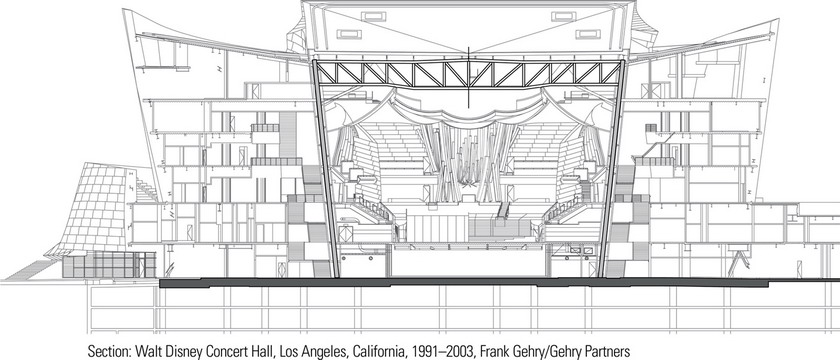
The Walt Disney Concert Hall is a complex steel framework of curves and shapes that required the use of a sophisticated software program developed for the French aerospace industry. The centerpiece of the building is the auditorium that is home to the Los Angeles Philharmonic and the Los Angeles Master Chorale. Long-span steel trusses span the large column-free space.
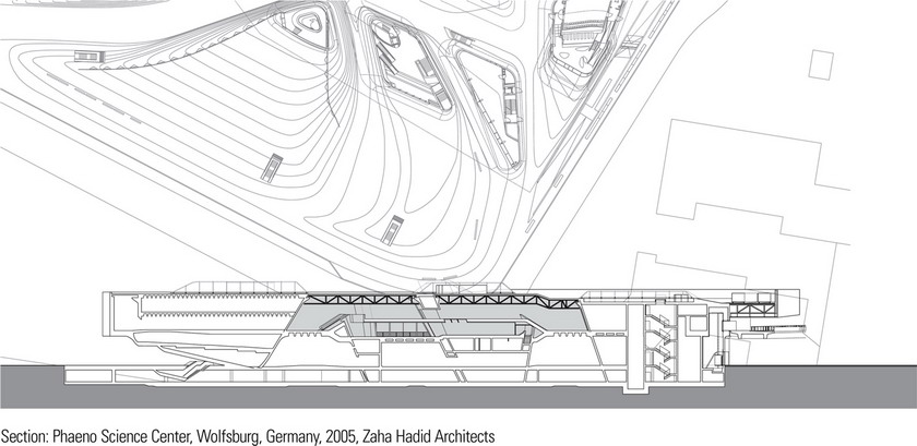
The roof of the central space of the Phaeno Science Center is supported by a long-spanning space frame. The center’s intricate forms were made possible by the use of advanced finite-element analysis modeling software developed by structural engineers Adams Kara Taylor. Complex forces within the entire structure were calculated and resolved as a single element, thus optimizing the integrity and material efficiency of the structure. If engineered in the traditional manner a few years ago, the structural systems would have been engineered separately, resulting in a significantly over-designed structure.
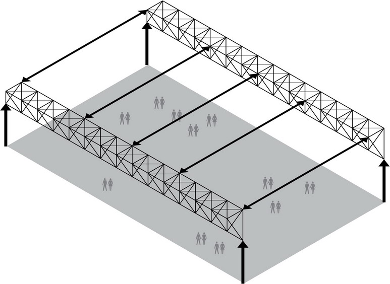
Space Trusses
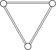
A space truss is a one-way structure that can be visualized as two planar trusses meeting each other at the bottom chord with the top two chords being framed as a third truss. This three-dimensional truss is now capable of resisting vertical, horizontal, as well as torsional forces.
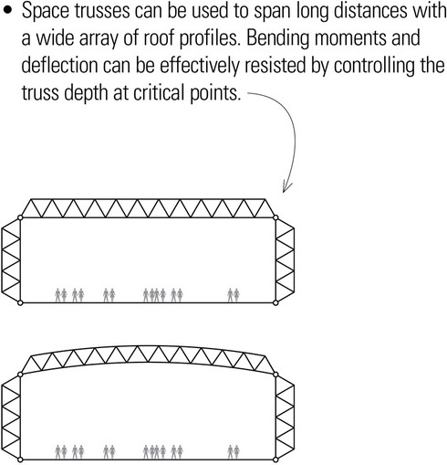
- The depth of space trusses fall in the range of span/5 to span/15, depending on the tributary load being carried and the magnitude of the deflection permitted for the long span.
- The spacing of space trusses depends on the spanning capability of secondary members. Loads from the secondary members should occur at panel joints to avoid inducing localized bending moments in the individual members.
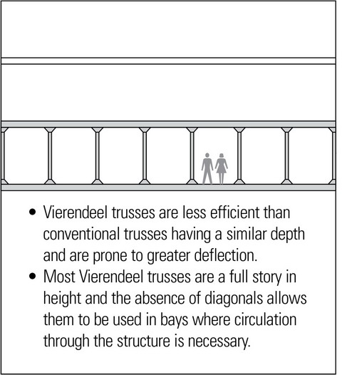
Vierendeel Trusses
A Vierendeel truss has vertical web members rigidly connected to parallel top and bottom chords. Because it has no diagonals, it is not a true truss and behaves structurally as a rigid frame structure. The top chord resists compression forces while the bottom chord is stressed in tension, similar to a true truss. However, because no diagonals are present, the chords must also resist shear forces and bending moments develop at the joints between the chords and vertical web members.
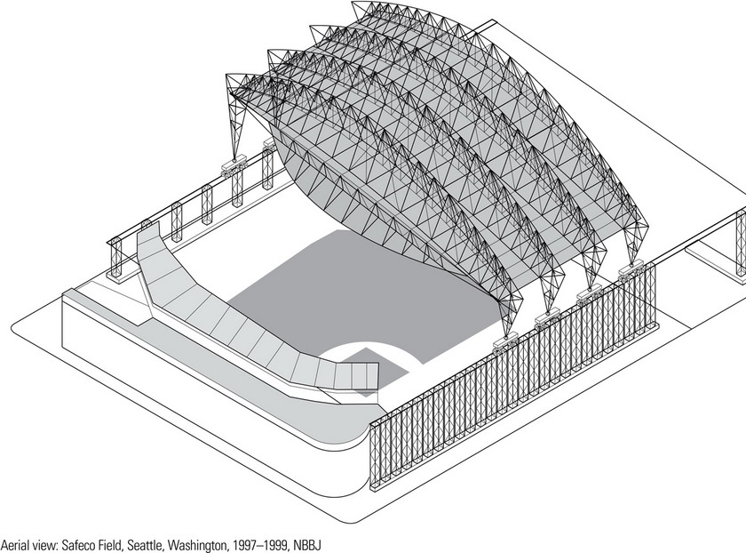
The retractable roof of Safeco Field consists of three moveable panels covering an area of 9 acres when closed. The roof panels are supported by four space trusses that glide on 128 steel wheels powered by 96 ten-horsepower electric motors; a push of a button can close or open the roof in 10 to 20 minutes. For closing, roof panels 1 and 3, which span 631 feet (192 m) tuck inside panel 2, which spans 655 feet (200 m).
The roof was designed to support 80 to 90 psf or up to 7 feet (2.1 m) of snow and operate in sustained winds of up to 70 mph. The moveable trusses supporting the three roof panels have fixed moment connections on one side and pinned and dampened connections on the other side. This enables the roof to flex in high winds or during seismic events without overstressing truss components or carrying horizontal forces down to the runway tracks.
LONG-SPAN ARCHES
Arches are designed to support vertical loads primarily by axial compression. They use their curvilinear form to transform the vertical forces of a supported load into inclined components and transmit them to abutments on either side of the archway.
Fixed Arches
A fixed arch is designed as a continuous member, rigidly connected to both base supports. The arch must be designed to resist bending stresses throughout its length and at both of its supports. The shape of the fixed arch will generally exhibit a deeper section at the supports and a gradual decrease in the cross section at the crown. Fixed arches are generally constructed of reinforced, prestressed concrete or of steel sections.
- While circular arches are generally easier to construct, funicular arches are subject to a minimum of bending stresses.
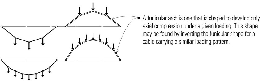
- There is no single funicular shape for an arch since it may be subject to many possible load conditions. If the loading pattern for which a funicular arch is designed changes, it would be subject to bending.
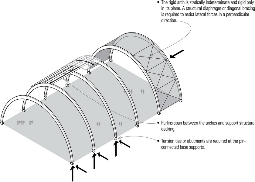
Rigid Arches
Contemporary arches consist of curved rigid structures of timber, steel, or reinforced concrete capable of carrying some bending stresses. Their structural behavior resembles that of rigid or moment-resisting frames. The geometry of the curves that replace the straight segments of the gabled rigid frame affects not only the cost of construction but also the resulting stresses in the frame members since no single funicular arch shape is possible for all possible load conditions.
Two-Hinged Arches
Two-hinged arches are designed as a continuous structure with pin connections at both base supports. The pin joints prevent high bending stresses from developing by allowing the frame to rotate as a unit when strained by support settlements, and to flex slightly when stressed by changes in temperature. They are generally designed to be thicker at the crown to allow the load path to vary while limiting the magnitude of the bending stresses and retaining an arch-like form. Glue-laminated timber, fabricated steel sections, wood and steel trusses, and concrete have all been used in the construction of two-hinged arches.
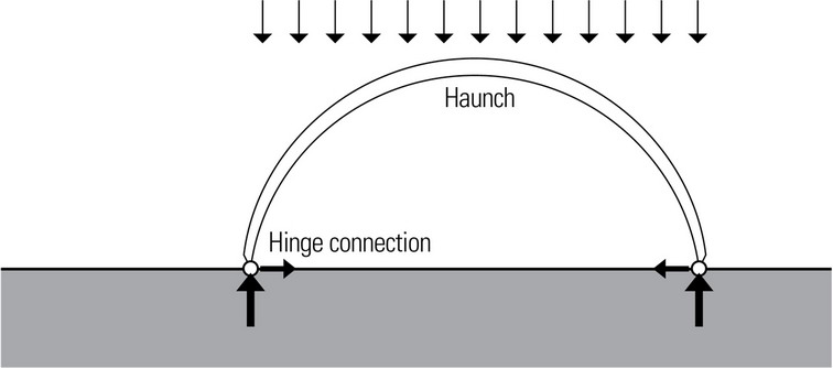
- Because the pinned connections develop no bending moments, they can usually be smaller in cross section and taper to the shoulder or haunch where the bending is largest and requires a larger section.
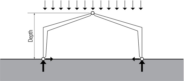
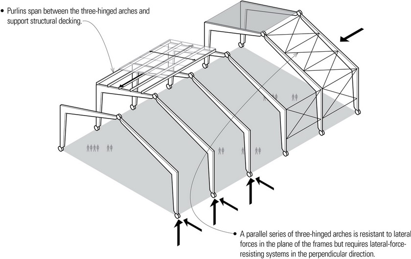
Three-Hinged Arches
Three-hinged arches are structural assemblies of two rigid sections connected to each other at the crown and to the base supports with pin joints. While more sensitive to deflection than either fixed or two-hinged frames, three-hinged arches are least affected by support settlements and thermal stresses. An advantage of three-hinged arches over two-hinged arches is their ease of fabrication as two or more rigid parts, which can then be transported to the construction site to be joined and erected.
- Long-span arches behave like rigid frames and may have either arched or gabled profiles.
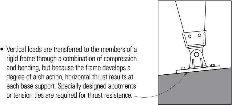
- Applied loads produce axial, bending, and shear forces in all members of a rigid frame because the use of moment-resisting joints restrain the ends of members from rotating freely.
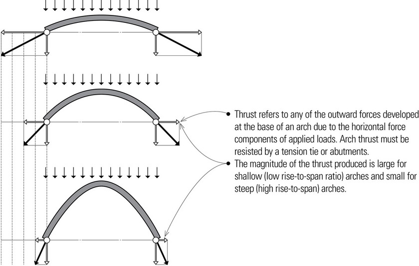
- Vertical loads are transferred to the vertical members of a rigid frame through a combination of compression and bending, but because the frame develops a degree of arch action, horizontal thrust results at each base support. Specially designed abutments or tension ties are required for thrust resistance.
- Glue-laminated timber arches are capable of spanning from 100 to 250 feet (30 to 76 m) with a depth to span ratio of about span/40. Transportation from the fabrication site to the construction site may be the limiting factor.
- Steel arches are capable of spanning in excess of 500 feet (152 m), especially if a trussed-arch system is used. Their depth range varies from span/50 to span/100.
- Concrete arches can span up to 300 feet (91 m) and have a depth range of about span/50.
Trussed arches and arched frames can often be a more economical alternative to monolithic rigid arches. They are more adaptable to fabrication in multiple sections for transportation to and joining at the construction site. Spans are generally under 150 feet (45.7 m) but can be made longer.
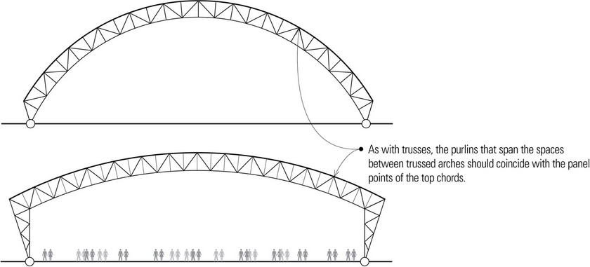
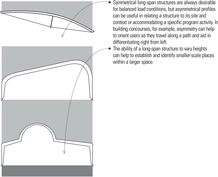
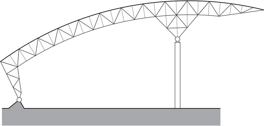
- The profiles of trussed arches alter both the form of the interior space as well as the exterior form of the structure.
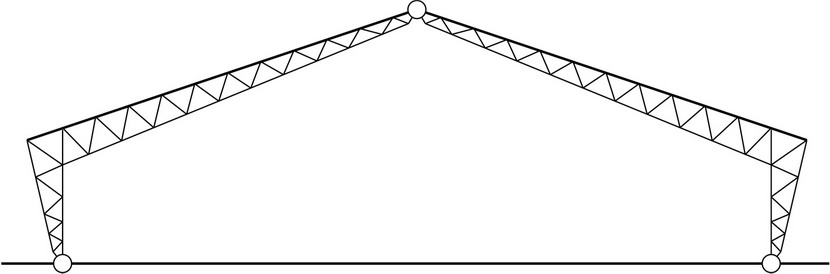
- While appropriate for sheltering an exterior space, this asymmetrical structure may be difficult to enclose and weatherproof.
The arch-shaped glue-laminated members that form the soaring roof of America’s Car Museum represent one of the world’s largest wood moment-frame systems.The arched timbers vary in size to accommodate the asymmetrical roof taper at the front and rear of the structure. Because the roof curves in two directions, each of the 757 purlins were cut to unique dimensions.
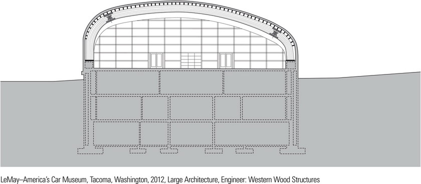
Special steel connections were designed to provide ductility in the arch systems, allowing the steel to yield plastically during a seismic event. The aim was to prevent the glue-laminated members from failing in a brittle fashion.
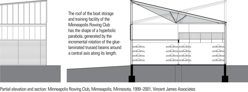
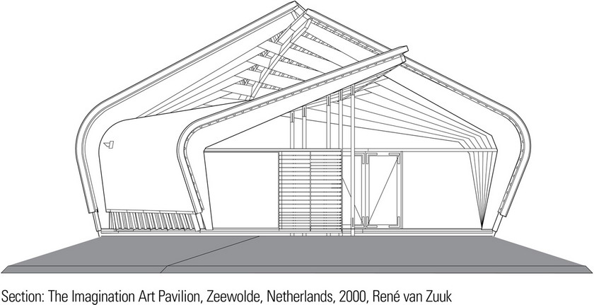
A limited budget led the architects to use three-hinged arched frames, patterned after those often used in local barn structures. All of the bents are identical but tilted at a slightly different angle relative to the ground plane. The resulting shifting and twisted roof surfaces almost meet along a fractured ridge line, which is glazed to admit indirect daylight.
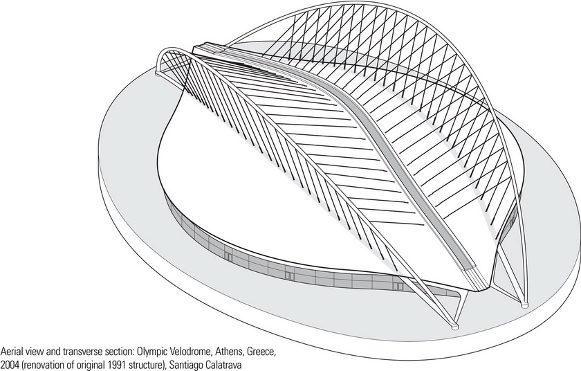
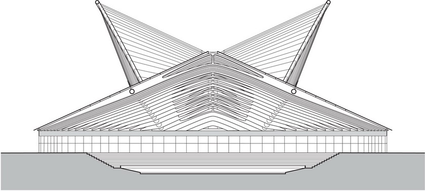
The roof structure of the Olympic Velodrome is composed of two massive tubular arches, each weighing 4000 tons, from which 40 transverse ribs are suspended. There are 23 unique ribs, each used twice in the symmetrical structure. The last three ribs at each end are supported by the rim tube. The doubled cables from the upper arch not only carry part of the roof load but also help stabilize the structure laterally through its triangulated geometry.
CABLE STRUCTURES
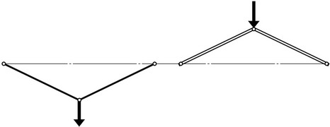
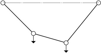
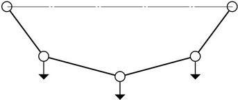
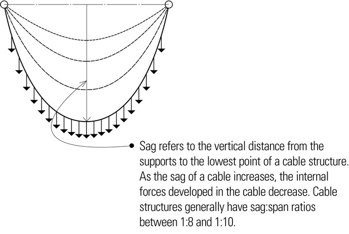
Cable structures use the cable as the principal means of support. Because cables have high tensile strength but offer no resistance to compression or bending, they must be used purely in tension. When subject to concentrated loads, the shape of a cable consists of straight-line segments. Under a uniformly distributed load, it will take on the shape of an inverted arch.
- A funicular shape is one that is assumed by a freely deforming cable in direct response to the magnitude and location of external forces. A cable always adapts its shape so that it is in pure tension under the action of an applied load.
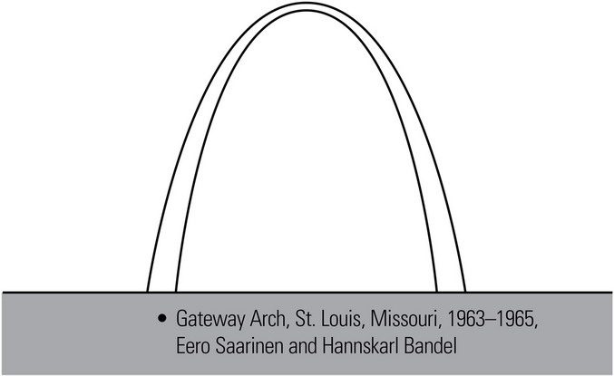
- A catenary is the curve assumed by a perfectly flexible, uniform cable suspended freely from two points not in the same vertical line. For a load that is uniformly distributed in a horizontal projection, the curve approaches that of a parabola.
- Single-cable structures must be carefully designed for uplift due to wind gusts and turbulence. Flutter or vibration present serious concerns in relatively light tensile structures.
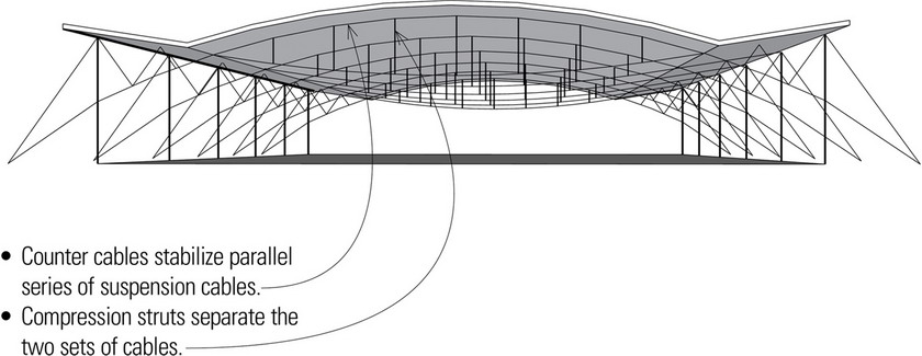
- Double-cable structures have upper and lower sets of cables of different curvatures, pretensioned by ties or compression struts to make the system more rigid and resistant to flutter.
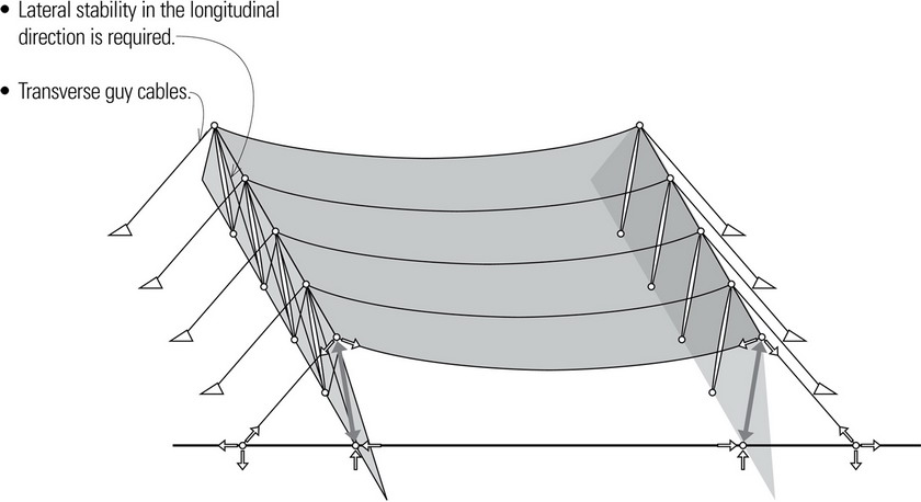
Singly-Curved Structures
Single-curvature structures use a parallel series of cables to support surface-forming beams or plates. They are susceptible to flutter induced by the aerodynamic effects of wind. This liability can be reduced by increasing the dead load on the structure and anchoring the primary cables to the ground with transverse guy cables.
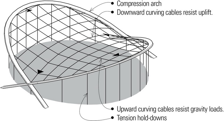
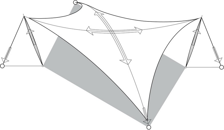
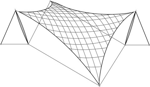
Double-Curvature Structures
Double-curvature structures consist of a field of crossed cables of different and often reverse curvatures. One set of cables counteracts wind-induced uplift while the other set of reverse curvature resists gravity loads from above.
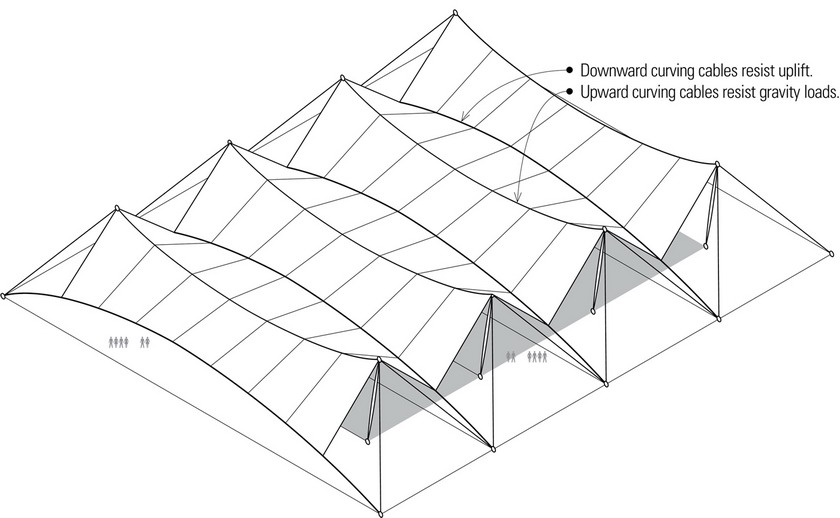
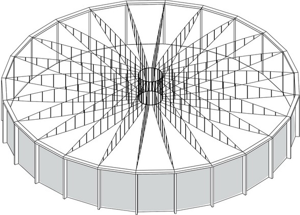
Structural cables of high-strength steel can be stretched, crisscrossed, and combined with surfacing materials to achieve relatively lightweight, long-span roof structures. Illustrated on this page are three of the numerous cable structure configurations that are possible.
- Surface consists of fabric material of woven high-strength fibers, coated to resist ultraviolet rays and weathering.
- Forces perpendicular to the surface can cause large cable forces and deformations, which must be countered by cables of opposing curvature.
- Vertical gravity forces
- Wind-induced uplifting forces
- Ponding rainwater or drifting snow can cause localized or unbalanced loading on roof structure.
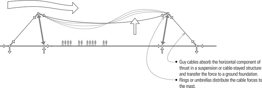
Cable-Stayed Structures
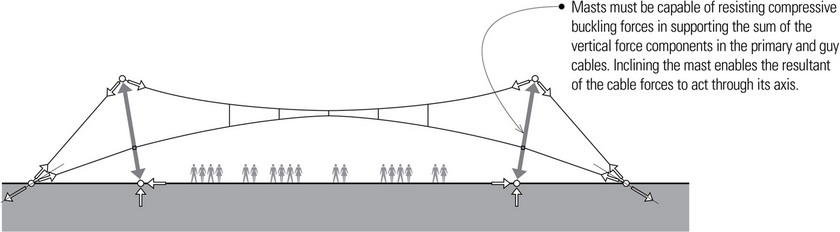
Cable-stayed structures consist of towers or masts from which cables extend to support horizontally spanning members. The cables must have not only sufficient capacity to carry the dead load of a structure, but also enough reserve capacity to carry the live load as well. The supported structural surface must be sufficiently stiff to transfer or resist the lateral and torsional stresses induced by wind, unbalanced live loads, and the normal force created by the upward pull of the stays.
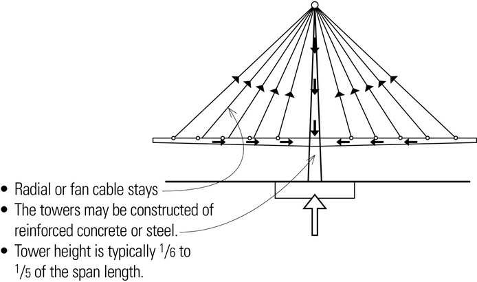
The cable stays are usually attached symmetrically to a single tower or mast with an equal number of stays on both sides so that the horizontal force component of the inclined cables will cancel each other out and minimize the moment at the top of the tower or mast.
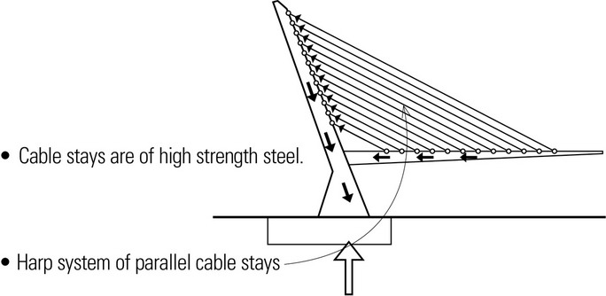
There are two primary cable configurations: radial or fan patterns and parallel or harp systems. Radial systems attach the upper ends of the cable stays to a single point at the top of the tower, while parallel systems secure the upper ends of the cable stays to the mast at different heights. The radial system is usually preferred because the single point of attachment minimizes the bending moment in the tower.
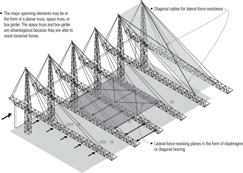
This cable-stayed structure supports a very large roof area with a minimal amount of supporting structure at the ground level. However, large uplifting wind forces may require a restraint system along the overhanging roof edge.
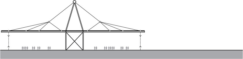
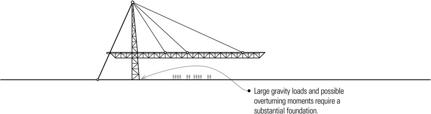
The cable-stayed structure defines large column-free spaces to either the side of the central support system. Tension members or hold-downs are required to resist uplifting wind forces.
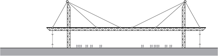
This cable-stayed system uses two of the structures in the top example to increase the coverage and provide a very large column-free space.
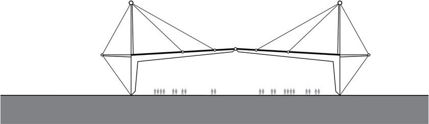
This concept uses a three-hinged frame whose horizontal span is increased through the use of the cable stays.
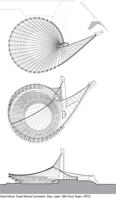
Arena Minore is the smaller of the two arenas that comprise the Yoyogi National Gymnasium designed by architect Kenzo Tange for the 1964 Olympics in Toyko. The structural scheme for both arenas involves the suspension of roof cables from two masts in the case of Arena Maggiore (page 73) and a single mast for Arena Minore.
The single main suspension cable of the Arena Minore spirals in a helix from the top of a concrete mast down to a concrete abutment at the entry. From this cable, which is held off of the mast by compression struts, are suspended lightweight trusses that span the main space to the perimeter abutment. A continuous foundation connects this abutment and the base of the mast to counter the extreme tensile force in the main cable.
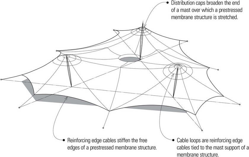
MEMBRANE STRUCTURES
Membrane Structures
Membrane structures consist of thin, flexible surfaces that carry loads primarily through the development of tensile stresses.
Tent structures are membrane structures prestressed by externally applied forces so that they are held completely taut under all anticipated load conditions. To avoid extremely high tensile forces, a membrane structure should have relatively sharp curvatures in opposite directions.
Net structures are membrane structures that have a surface of closely spaced cables instead of a fabric material.
Pneumatic structures are membrane structures that are placed in tension and stabilized by the pressure of compressed air.
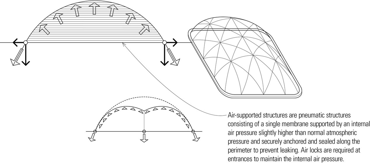
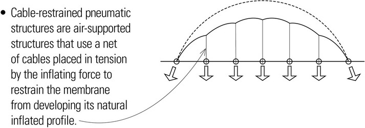
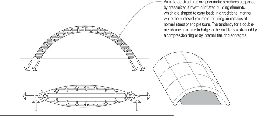
PLATE STRUCTURES
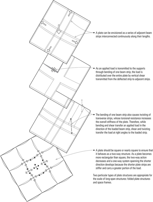
Plate structures are rigid, planar, often monolithic structures that disperse applied loads in a multidirectional pattern, with the loads generally following the shortest and stiffest routes to the supports. A common example of a plate structure is a two-way reinforced concrete slab.
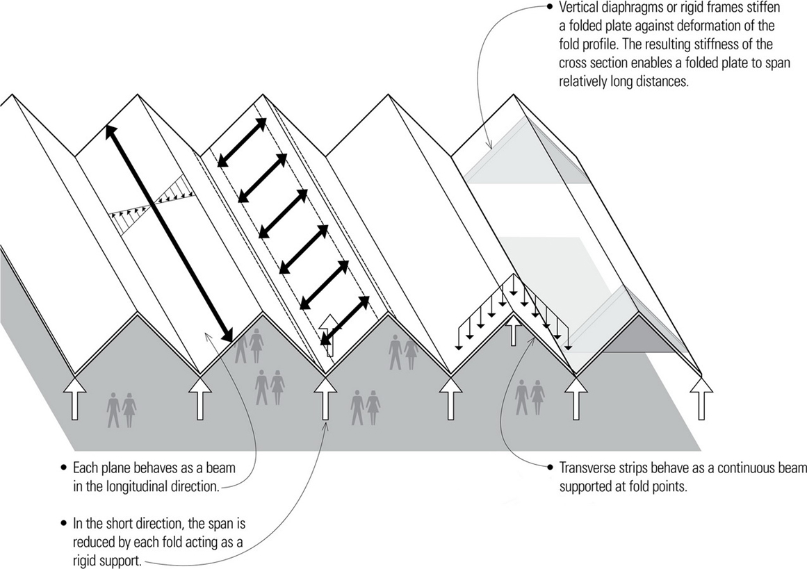
Folded Plate Structures
Folded plate structures are composed of thin, deep elements joined rigidly along their boundaries and forming sharp angles to brace each other against lateral buckling.
- Folded plate structures are usually constructed of reinforced concrete but stiffened plywood plates can also be used.
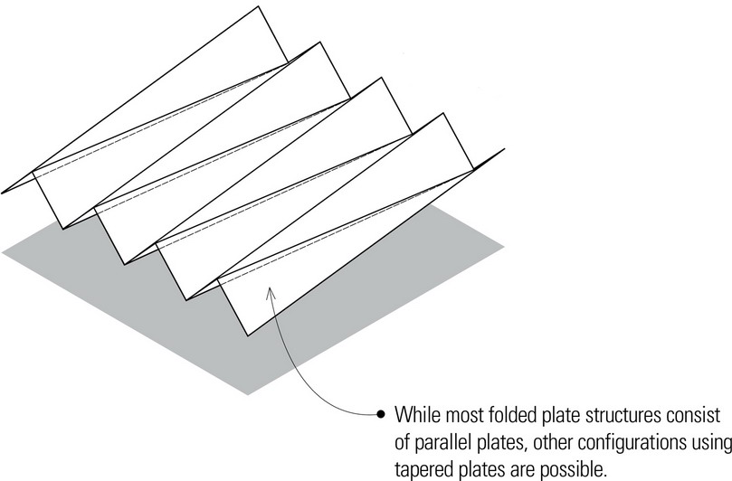
- The greater the depth of a folded plate structure, the more resistant it is to bending. The shallower the structure, the more susceptible it will be to bending.
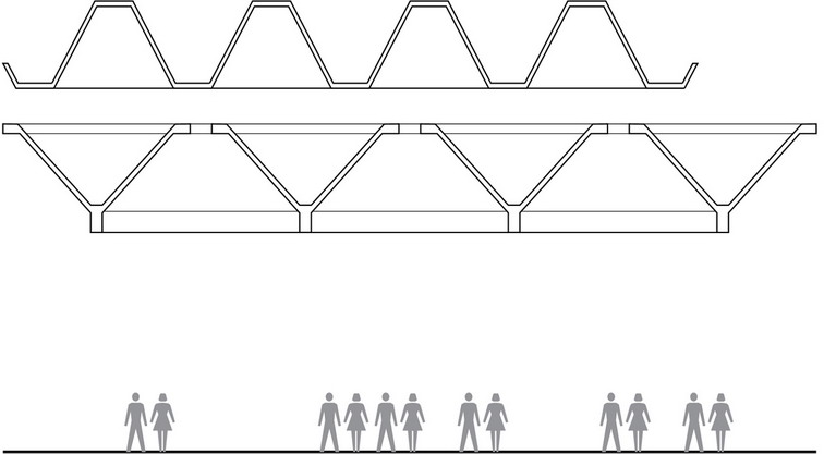
- Illustrated are two of numerous possible profiles.
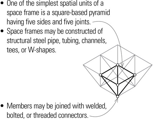
Space Frames
Space frames are three-dimensional structural frames based on the rigidity of the triangle and composed of linear elements subject only to axial tension or compression. The relatively lightweight, long-span structures are used primarily for roof construction and often at least partially glazed for natural daylighting. The constituent parts can be assembled on-site at the ground level and lifted or jacked into position; no large equipment is required for erection. As with plate structures, the supporting bay for a space frame should be square or nearly square to ensure that it acts as a two-way structure.
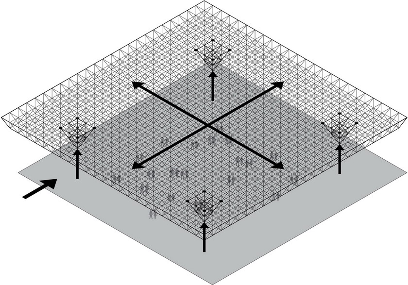
- Space frame should be sloped or cambered to drain.
- Roof connections should be made at panel points.
- Steel construction may be left exposed if at least 20′ (6.1 m) above the occupied floor; consult the building code for requirements.
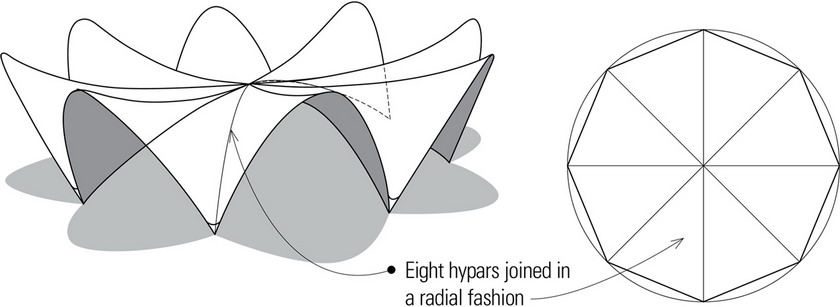
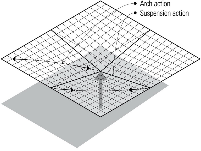
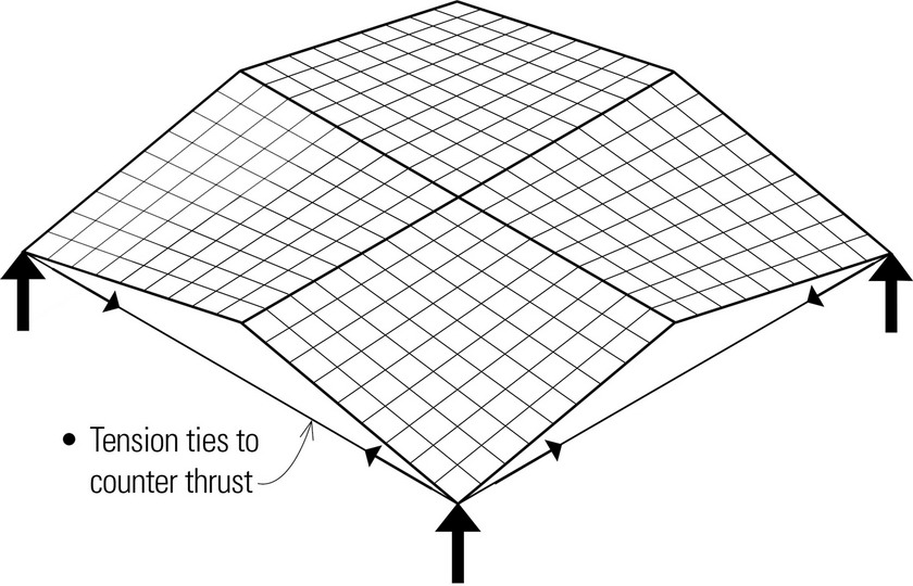
SHELL STRUCTURES
Shells are thin, curved plate structures typically constructed of reinforced concrete and used for the roofs of buildings. They are shaped to transmit applied forces by membrane stresses—the compressive, tensile, and shear stresses acting in the plane of their surfaces. A shell can sustain relatively large forces if uniformly applied. Because of its thinness, however, a shell has little bending resistance and is unsuitable for concentrated loads.
Types of Shell Surfaces
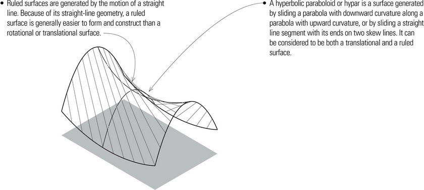
- Translational surfaces are generated by sliding a plane curve along a straight line or over another plane curve.
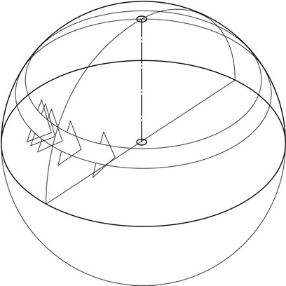
- Rotational surfaces are generated by rotating a plane curve about an axis. Spherical, elliptical, and parabolic dome surfaces are examples of rotational surfaces.
Any number of formal and spatial compositions can be created by combining geometric surfaces. For constructibility, the intersection of any two shells should be coincident and continuous.
Gridshells
Gridshells consist of discrete members connecting nodal points that lie on the surface of an imaginary shell. Whereas solid shell surfaces have an infinite number of load paths, gridshells have internal forces that are carried by the grid members along a finite number of load paths. Gridshells are often free-form and due to the presence of some bending stresses, the wood or steel members are required to resist loading through their cross section.
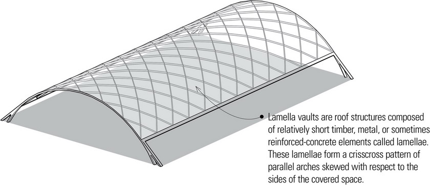
- Diagrids are a subset of gridshells. See In-Plane Curtain Walls and Diagrid Structures.
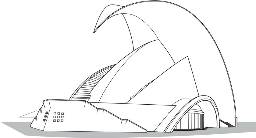
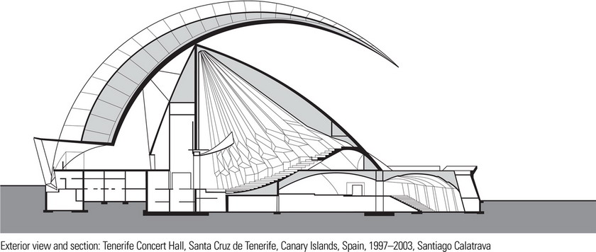
Tenerife Concert Hall is a reinforced concrete structure that houses a main auditorium that seats 1600 and a smaller chamber music hall that seats 400. The cantilevered roof shell, constructed from two intersecting cone segments and designed to be supported on only five points, soars to a height of 190 feet (58 m) over the main auditorium before curving downward to a point. The symmetrical inner shell of the concert hall, 165 feet (50 m) high, is a rotational body, generated by rotating a curve to describe an ellipse. A wedge of approximately 15° has been removed from the center of this body so that its two segments form a pronounced ridge like that of a folded plate. Wide arches spanning 165 feet (50 m) on each side serve as the artists’ entrances.
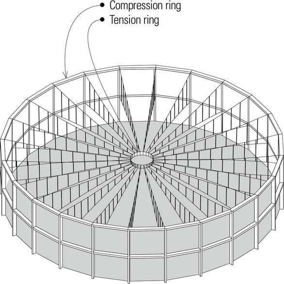
Domes
A dome is a spherical surface structure having a circular plan and constructed of a continuous rigid material like reinforced concrete, or of short, linear elements, as in the case of a geodesic dome. A dome is similar to a rotated arch except that circumferential forces are developed which are compressive near the crown and tensile in the lower portion.

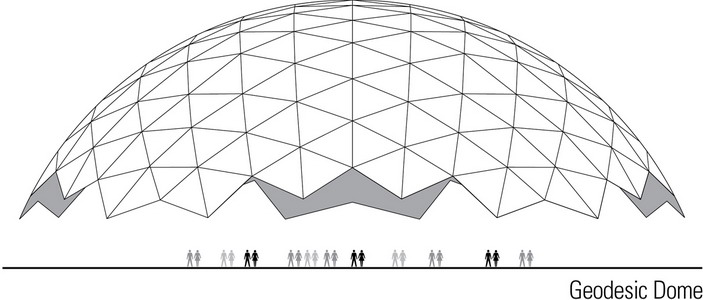
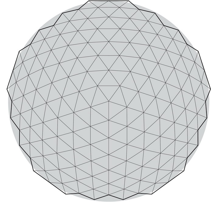
- Geodesic domes are steel dome structures having members that follow three principal sets of great circles intersecting at 60°, subdividing the dome surface into a series of equilateral spherical triangles.
- Unlike lattice and Schwedler domes, geodesic domes have irregular base profiles, which can create difficult support conditions.
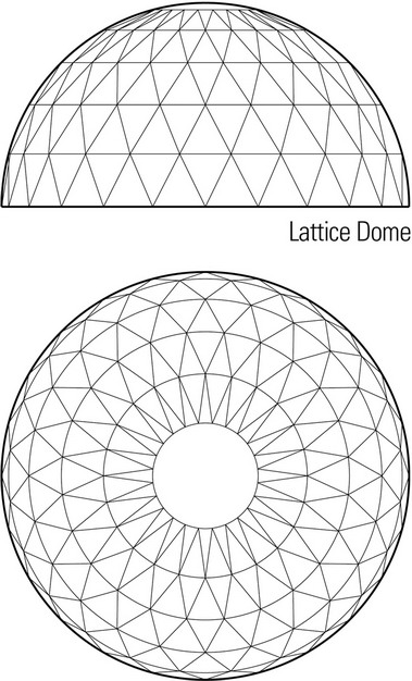
- Lattice domes are steel dome structures having members that follow the circles of latitude, and two sets of diagonals forming a series of isosceles triangles.
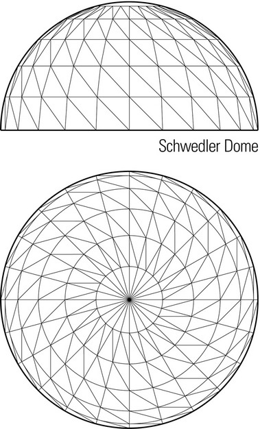
- Schwedler domes are steel dome structures having members that follow the lines of latitude and longitude, and a third set of diagonals completing the triangulation.
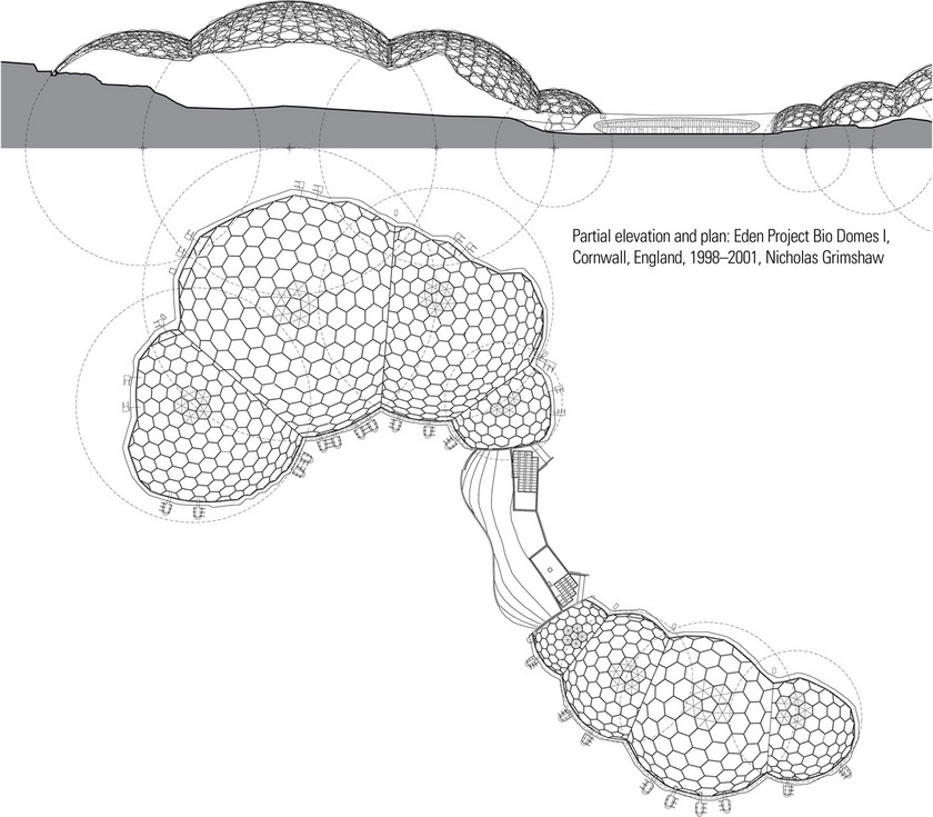
The Eden Project, the world’s largest greenhouse, covers an area of 5.4 acres (2.2 hectares). It consists of two climate-controlled biomes, built up from eight interconnected geodesic spheres ranging in radius from 59 feet (18 m) to 213 feet (65 m). Each geodesic shell is braced with a secondary structure of diagonal tubing and enclosed with a high-strength and corrosion-resistant polymer foil of ethylene tetrafluoroethylene or (ETFE) that maximizes surface area while minimizing perimeter detailing.
The design required that the length of each steel section be calculated using a three-dimensional computer model, enabling each section to be prefabricated off-site and assembled in its unique position on-site. The final design is highly efficient, providing maximum strength with minimum steelwork and defining maximum volume with minimum surface area.