Modeling a Single Neuron
Pascal Wallisch
Neurons communicate with each other by transmitting and receiving electrochemical signals called action potentials. These action potentials are transient fluctuations in the cell’s membrane potential, which propagate down a cell’s axon without attenuation. In the central nervous system, action potentials have a duration on the order of milliseconds (1–2 msec usually) and can often be divided into three phases. The first phase of the action potential is a rapid depolarization of the membrane called the rising phase or upstroke of the action potential. This is followed by a repolarization of the membrane called the falling phase or downstroke of the action potential. The last phase follows a hyperpolarization of the membrane and is called the undershoot. This chapter will result in a system of four ordinary differential equations that model action potential generation in neurons.
Keywords
action potentials; rising phase; upstroke; falling phase; downstroke; undershoot; sodium reversal potential; Ohmic resistors
27.1 Goal of This Chapter
The goal of this chapter is to incorporate previous models of voltage-gated ion channels into a model of single neuron dynamics. This chapter will continue to follow work done by Hodgkin and Huxley (1952) resulting in a system of four ordinary differential equations that model action potential generation in neurons.
27.2 Background
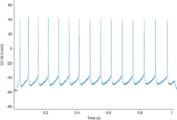
Neurons communicate with each other by transmitting and receiving electrochemical signals called action potentials. These action potentials are transient fluctuations in the cell’s membrane potential, which propagate down a cell’s axon without attenuation. In the central nervous system, action potentials have a duration on the order of milliseconds (1–2 msec usually) and can often be divided into three phases. The first phase of the action potential is a rapid depolarization of the membrane called the rising phase or upstroke of the action potential. This is followed by a repolarization of the membrane called the falling phase or downstroke of the action potential. The last phase follows a hyperpolarization of the membrane and is called the undershoot. A depiction of the action potential is shown in Figure 27.1.

Figure 27.1 Intracellular action potential spike train from a deep pyramidal neuron recorded from the frontal cortex of a mouse. (Courtesy of Amber Martell)
Some of the earliest experiments to elucidate the mechanism underlying action potentials were performed by Hodgkin and Katz (1949), who showed that reducing the extracellular concentration of sodium led to a shorter upstroke phase of the action potential in giant squid axon. They inferred from this that the upstroke of the action potential depends on the cell increasing its permeability to sodium. They also suggested that the falling phase was due to an increase in potassium permeability. Therefore, they concluded that the action potential was generated by selective changes in membrane permeability to sodium and potassium. We now know that ion channels are responsible for this selective permeability. These experiments were later followed up by Hodgkin and Huxley (1952), who performed voltage-clamp experiments to characterize the dynamics of these changes in permeability and then proposed the mathematical model of action potential generation outlined in the following section.
27.2.1 The Model
Neurons are incredibly complex. Like all eukaryotic cells, they are composed of many organelles, including a nucleus, mitochondria, an endoplasmic reticulum, etc. Each of these organelles has a role that enables the cell as a whole to perform its functions, including generating action potentials. Trying to capture all the complexity of a real neuron in a single model is impossible. Fortunately, it is also unnecessary, since, for purposes of this chapter, you are interested only in understanding action potential generation in neurons, and not any of the other complex processes that neurons undergo. Therefore, you should restrict your neuron model to include only those elements that contribute most directly to generating action potentials and ignore elements of a neuron that contribute less to action potential generation. In general, it is often not clear what elements of a complex biological system are most directly related to a behavior of interest, and the choices you make in constructing a model are often not validated until the results of the model can be compared to experiments.
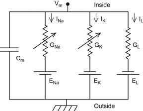
In this model, assume that action potential generation in neurons is mainly carried out by the electrical properties of the cell membrane. Several factors contribute to the electrical properties of the cell membrane. For instance, ion channels such as Nav, Kv, and leak channels span the membrane and selectively pass ions across it. The voltage-gated channels are represented in Figure 27.2 as variable resistors (the resistors with an arrow going through them) because the amount of resistance to flow depends on the membrane potential, whereas the leak channel, which has a constant resistance to ion flow, is represented by an ordinary resistor. The phospholipids that comprise the membrane, which do not conduct electric charges, allow for most of the cell membrane to function as a dielectric, an insulative material that separates ions in the cytoplasm from those in the extracellular milieu. Although ions cannot flow through the phospholipid bilayer of the cell directly, charge can accumulate on one side of the cell membrane, inducing an opposed charge buildup on the opposite side of the membrane just as a capacitor does. This charge buildup involves charges moving toward the membrane and represents a capacitive current. Finally, the cell membrane contains many other transmembrane proteins such as the Na+/K+-ATPase that helps maintain ion concentration gradients across the cell membrane. The presence of a sodium concentration gradient, for example, ensures that when sodium ions have equilibrated across the Nav channels of the neuron, there will be a nonzero potential across the membrane. This potential is called the sodium reversal potential. Similarly, there will be a reversal potential for the Kv channel. The electrical properties mentioned so far can be summarized by creating an electric circuit equivalent to the neuronal model. The circuit is shown in Figure 27.2. Notice that current flows from the inside of the cell (at the top of the electrical circuit) to the outside of the cell by either inducing a charge buildup at the membrane (represented by the capacitor) or by flowing through one of the three ion channels present in the membrane. From simple electrical circuit theory, you can represent the following circuit using a set of equations. In the next section, we will review the important concepts of electrical circuits needed to understand the circuit in Figure 27.2.

Figure 27.2 An electrical circuit diagram of a single axonal compartment of a neuron. (Bower JM, Beeman D. The Book of Genesis: Exploring Realistic Neural Models with the GEneral NEural SImulation System, 2003)
To express the circuit as a set of equations, you need to know four fundamental laws of electronics. The first is Ohm’s law, which states that for some resistors (called Ohmic resistors) the voltage drop across the resistor, VR, is related to the current flowing through the resistor, I, and the resistance of the resistor, R, by the equation:
 (27.1)
which can also be written as:
 (27.2)
where g is the conductance of the resistor (note g1/R). The second law you will need states that the voltage drop across a capacitor, VC, is related to the current induced by the capacitor, I, and the capacitance of the capacitor, C, by the equation
 (27.3)
The last two laws that you will need are collectively known as Kirchhoff’s Loop Rules. The first rule, Kirchhoff’s Current Rule, states that the sum of current entering a circuit junction equals the sum of current exiting it, and a circuit junction is any intersection of wire where current has more than one path to flow down. The equation for this rule is given by:
 (27.4)
The second rule, Kirchoff’s Voltage Rule, states that the potential drop between any two points on a circuit is independent of what path was taken to arrive there. If you assume that the start and end point are the same, then this rule implies that the voltage drop across any closed loop is zero, and can be written as:
 (27.5)
Now you can use these simple rules to calculate the membrane potential of the circuit in Figure 27.2. The membrane potential is defined as the potential difference between the inside and the outside of the cell. Therefore, in Figure 27.2 the membrane potential is the potential drop across any path from the inside of the cell to the outside. Beginning with the path that includes the capacitor, you see that the voltage drop across the capacitor is just the membrane potential, so Equation 27.3 becomes:
 (27.6)
which can be rearranged to give:
 (27.7)
Now examine the potential drop across the second path (the sodium channel), which consists of two elements, a resistor and a battery. The total drop across both these elements is just the potential difference between the inside and outside of the cell, VM, so:
 (27.8)
Upon substitution into Equation 27.2, you have:
 (27.9)
Following the same process across the last two paths produces equations nearly identical to Equation 27.9 for IK and IL:
 (27.10)
 (27.11)
Finally, use Kirchhoff’s Current Rule to see that if you inject a current into the cell of Iinj, then:
 (27.12)
Rearranging Equation 27.12 and substituting in Equations 27.7 and 27.9 through 27.11 gives:
 (27.13)
Recall that the sodium and potassium channels are voltage-gated, so their conductances are functions of voltage. In Chapter 25, “Voltage-Gated Ion Channels,” you modeled the potassium conductance as:
 (27.14)
where
 (27.15)
and the sodium conductance by:
 (27.16)
where
 (27.17)
If you substitute Equation 27.14 and 27.16 into Equation 27.13 and collect Equations 27.15 and 27.17, you get the following system of equations:
 (27.18)
In the original Hodgkin-Huxley model, the final equations proposed were as follows:
 (27.19)
The changes to the first equation were made so that the model would better fit with the experimental data, although some explanation of the addition of these exponents has since been made from first principles.
Many of the parameter values needed to evaluate the system of Equation 27.19 are mentioned in Chapter 25, “Voltage-Gated Ion Channels.” Table 27.1 identifies these parameter values along with some additional parameter values for the leak channel and capacitance of the membrane.
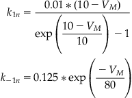
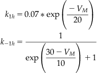
The functional forms for the transition rates between conformational states of the sodium and potassium channels are given in Equations 27.20–27.22. These rates were discussed in more detail in Chapter 25, “Voltage-Gated Ion Channels.”
 (27.20)
 (27.21)
 (27.22)
27.3 Exercises
Trying to write code to implement a set of equations such as Equation 27.19 while keeping track of all the rate functions and necessary parameters can seem daunting. The key to keeping larger coding projects manageable is to write many smaller functions first and then put them together to create larger functions until eventually the project is complete. For example, the following code is for a function n_prime that takes the current value of n and the current membrane potential V_m and returns the derivative of n according to the second equation of the Hodgkin-Huxley model:
%This function takes two arguments the membrane potential and the current value %of the state variable n, and returns the value of the derivative of n for these values.
%First calculate the values of the forward and backward rate constants, k_1n and %k_2n.
k_1n=0.01*(10-V_m)/(exp((10-V_m)/10)-1);
27.4 Project
In this project, you will model the voltage dynamics of a Hodgkin-Huxley neuron. You should perform the following:
1. Write a function hodgkin_huxley(t, I_inj) that takes a time series t and a constant representing injected current and returns the value of V at every point in t. Assume that the initial value for V is −10 mV. Assume that all channels are initially closed. Hint: See Chapter 25, “Voltage-Gated Ion Channels,” for a similar example.
2. Plot V versus t for injected currents of 5, 10, and 15 A/cm2.
3. Determine what happens to the frequency of firing as the injected current increases.
4. Indicate how the action potential generated by this model compares to the result in Figure 27.1.
