29
CHAPTER
Room Air Conditioners
Room air conditioners (RACs) are available in different sizes (rated in BTUs) and cabinet styles.1 These units can be installed in a window or through the wall, or are available as a portable unit on wheels (Figure 1-16). Manufacturers have designed RACs with electromechanical controls or electronic controls. Consumers can purchase an RAC that is straight cool only, cool with heat (electric), heat pump (reverse cycle), or a combination of cool and heat (electric heat and reverse cycle).
The room air conditioner consists of the following:
• The base pan, fan housing, divider section (bulkhead), and outer cabinet
• The sealed system, which consists of the evaporator coil, the condenser coil, the compressor, and the connecting tubing
• The electrical circuitry, including the fan motor and other electrical components
Principles of Operation
The room air conditioner, when installed and running properly, will circulate the air in a room or area, removing the heat and humidity; some models will heat the air in the winter months. At the same time, the air filter, located behind the front grille, will filter out dust particles. Most models have a fresh air intake feature, which allows fresh outside air to enter the room when the unit is running. The thermostat will control the comfort level in the room or area, and cycle the air conditioner on and off according to the temperature setting.
Before continuing, take a moment to refresh your memory of Chapter 9. These two chapters combined will make servicing room air conditioners a breeze.
Safety First
Any person who cannot use basic tools or follow written instructions should not attempt to install, maintain, or repair any room air conditioners. Any improper installation, preventive maintenance, or repairs could create a risk of personal injury or property damage. If you do not fully understand the installation, preventive maintenance, or repair procedures in this chapter, or if you doubt your ability to complete the task on your room air conditioner, please call your service manager.
This chapter covers the electrical components and how to diagnose the sealed system. The actual repair or replacement of any sealed-system component is not included in this chapter. It is recommended that you acquire refrigerant certification (or call an authorized service company) to repair or replace any sealed-system component, as the refrigerant in the sealed system must be recovered properly.
Before continuing, take a moment to refresh your memory on the safety procedures in Chapter 2.
Room Air Conditioners in General
Much of the troubleshooting information in this chapter covers room air conditioners in general, rather than specific models, in order to present a broad overview of service techniques. The illustrations that are used in this chapter are for demonstration purposes only, to clarify the description of how to service these appliances. They in no way reflect on a particular brand’s reliability.
Electrical Requirements
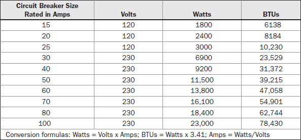
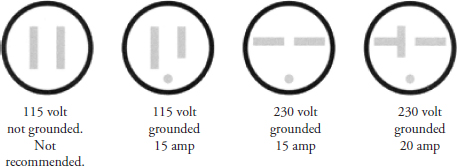
One of the most common problems that I have encountered over the years is when a consumer plugs the room air conditioner into an existing 115-volt receptacle only to find out that the circuit breaker keeps tripping. Most people do not take into account that this receptacle is connected to the other receptacles and/or lights in the same room and on the same branch circuit. This means that there is a limit to how many items can be connected to one branch circuit. Before a consumer purchases a room air conditioner, he or she needs to add up the total amperage or wattage of the items that are plugged into the branch circuit where the air conditioner is going to be plugged in. For example, on a 15-amp circuit, the total wattage on a 120-volt circuit should not exceed 1800 watts (Table 29-1). For safety reasons, all of the items, including the air conditioner, should stay below the amperage rating on the circuit breaker by 20 percent. The 115-volt, 15-amp circuit is reserved for lights, computers, televisions, stereos, etc. The 115-volt, 20-amp circuit is reserved for a refrigerator, dishwasher, automatic washer, or a garbage disposer only. Most 230-volt, 15- to 60-amp receptacles are on a single branch circuit. Figure 29-1 illustrates the type of plug connections needed for a room air conditioner. All room air conditioners and portable air conditioners must have a properly polarized and grounded receptacle, with the correct operating voltage for the unit purchased, preferably on its own branch circuit (Table 29-2). If the consumer only has multiple receptacles on one branch circuit, advise him or her to calculate the total amperage or wattage of each item (for example: television, computer, printer, computer monitor, lamps, microwave oven, etc.). Advise the consumer not to exceed the rated branch circuit, circuit breaker, or fuse. If the consumer does not correct the problem, this could lead to a possible fire hazard if the home wiring overheats.
TABLE 29-1 Conversion Formulas for Amps, Volts, Watts, and BTUs
FIGURE 29-1 An electrical receptacle guide illustrating the type of receptacle needed for the amperage rating.
TABLE 29-2 The Minimum/Maximum Operating Voltages for an Air Conditioner
Location and Installation of Room Air Conditioner
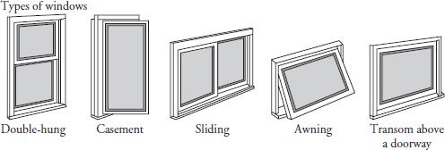
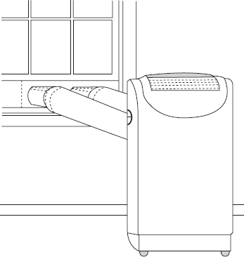
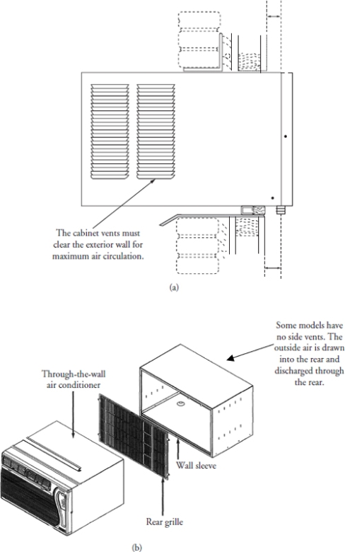
Room air conditioners and portable models can be installed in various types of windows (Figures 29-2 and 29-3) or through the wall (Figure 29-4) for permanent installation. It is the installer’s responsibility to make sure that the air conditioner is installed properly according to the manufacturer’s specifications and local building codes. If the air conditioner is installed in a window, the installer must make sure that the air conditioner is secured to the window so that it will not fall out, causing injury, death, or property damage. Through-the-wall models should be secured to the wall to prevent the unit from being pushed out of the wall when the unit is installed or serviced. Portable air conditioners are much easier to install. The air intake and discharge hoses are installed through a small opening in the window. This type of unit can be moved around from room to room easily.
FIGURE 29-2 Room air conditioners can be installed in these types of windows. When selecting an air conditioner to purchase, measure the window opening.
FIGURE 29-3 A typical portable air conditioner installation.
FIGURE 29-4 (a) A typical wall installation. The air conditioner must be installed with a slight pitch so that the condensate water can drain to the rear of the unit. (b) If the outside vents cannot clear the wall structure, purchase an air conditioner with a sleeve without side vents.
The following are some helpful tips when considering a location to install a window air conditioner:
• Make sure you have the correct size (BTUs) for the area being cooled.2
• When selecting an air conditioner, make sure that the air vents will be able to point to the center of the room for better air circulation.
• When purchasing a window air conditioner, purchase one that is designed for the type of window in the home (see Figure 29-2). This will make for an easier installation.
• Make sure the unit will fit the window opening. Measure the opening of the window.
• Check the electrical outlet voltage. The voltage should match the operating voltage of the unit being installed.
• The electrical outlet should not be farther away than the length of the service cord.
• For larger air conditioners, install the brackets that come with the air conditioner. These brackets will reduce the stress on the window.
• Make sure there is adequate airflow with no obstructions on the outside of the building.
• Do not install a room air conditioner in an area where the temperature will exceed 120 degrees Fahrenheit.
The following are some helpful tips when considering a location to install a through-the-wall air conditioner:
• Make sure you have the correct size (BTUs) for the area being cooled.2
• When selecting an air conditioner, make sure that the air vents will be able to point to the center of the room for better air circulation.
• Measure the depth of the wall where the air conditioner will be installed. Make sure that the outside louvers will not be blocked (see Figure 29-4).
• Purchase an air conditioner with a slide-out chassis or with a wall sleeve for easier installation.
• Check the electrical outlet voltage. It should match the operating voltage of the unit being installed.
• The electrical outlet should not be farther away than the length of the service cord.
• Make sure there is adequate airflow with no obstructions on the outside of the building.
• Do not install a room air conditioner in an area where the temperature will exceed 120 degrees Fahrenheit.
Step-by-Step Troubleshooting by Symptom Diagnosis
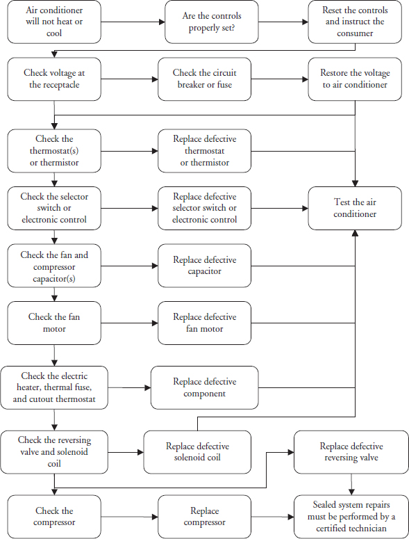
When servicing an air conditioner, don’t overlook the simple things that might be causing the problem. Step-by-step troubleshooting by symptom diagnosis is based on diagnosing malfunctions, with possible causes arranged into categories relating to the operation of the room air conditioner. This section is intended only to serve as a checklist to aid you in diagnosing a problem. Look at the symptom that best describes the problem you are experiencing with the air conditioner, and then correct the problem.
Air Conditioner Will Not Run
• Is the unit service cord plugged in?
• Check for voltage at the receptacle.
• Are the controls set properly?
• Check for a blown fuse or tripped circuit breaker. Check for total wattage on the branch circuit.
• Check the selector switch or electronic control board.
• Check all wiring connections and wiring.
Air Conditioner Will Not Cool or Cools Slightly
• Check for a dirty filter.
• Check for a dirty or restricted evaporator coil.
• Check for a dirty or restricted condenser coil.
• Check fan speed setting. Are the louvers adjusted correctly?
• Check the thermostat setting.
• Check the refrigeration cycle for leaks or an undercharge.
• Is the air conditioner the right size for the area to be cooled?2
• Is the fresh air intake or exhaust door open?
Compressor Will Not Run
• Check for the correct voltage at the receptacle.
• Check the control settings.
• Check the wiring connectors and wiring.
• Check the thermostat setting.
• Check the selector switch or electronic control board.
• Test the compressor for an open, short, or grounded winding.
• Test the overload.
• Test the compressor capacitor for an open, short, or ground.
Fan Motor Will Not Run
• Check the fan selector switch, main selector switch, or electronic control board.
• Check the wiring connectors and wiring.
• Test the fan capacitor for an open, short, or ground.
• Test the fan motor windings for an open, short, or ground.
Evaporator Coil Freezes Up
• Check for a dirty filter.
• Check for a dirty or restricted evaporator coil.
• Check the thermostat.
• Check fan motor.
• Check the refrigeration cycle for leaks, undercharge, or capillary tube restriction.
Condenser Coil Frozen (Heat Pump Models Only)
• Check defrost thermostat (outdoor thermostat) switch contacts and the capillary tube placement.
• Check the solenoid coil on the reversing valve.
• Check the reversing valve.
• Check the control settings.
Compressor Runs Continually and Will Not Cycle Off
• Check for excessive heat load. Is the air conditioner the right size for the area to be cooled?2
• Check for a partial refrigeration restriction in the line. Is the evaporator coil partially iced up?
• Check for a refrigerant leak.
• Check the running amperage against the model number identification plate on the air conditioner.
• Check the thermostat for proper operation.
Thermostat Will Not Cycle Off the Air Conditioner
• Check for stuck thermostat contacts.
• Check the thermostat setting.
• Check the wiring connections. Is the thermostat wired correctly?
• Is the air conditioner the right size for the area to be cooled?2
Thermostat Will Not Cycle the Air Conditioner On
• Check the thermostat bulb and capillary tube for loss of charge.
• Test the thermostat.
• Check the wiring connections and wiring.
• Check the control settings.
Thermostat Will Short-Cycle
• Is the air conditioner the right size for the area to be cooled?2
• Check for a dirty or restricted evaporator coil.
• Check for a dirty filter.
• Check the positioning of the thermostat bulb. Test the thermostat differential.
• Check and make sure that the plenum gasket is sealing properly.
• Check for outside air leakage into the air conditioner.
Compressor Runs and then Cycles on Overload
• Check for low voltage at the receptacle.
• Check the compressor overload.
• Did the compressor restart before the sealed system had a chance to equalize? Advise the customer to wait about three or four minutes after the air conditioner cycles off before restarting the compressor.
• Check the wiring connections and wiring.
• Check the compressor capacitor for an open, short, or ground.
• Check for a dirty or restricted condenser coil.
• Check the amperage of the air conditioner.
• Check for a kinked discharge line.
Air Conditioner Is Noisy
• Check the air conditioner installation.
• Make sure the fan blade and blower wheel are not striking the chassis.
• Check the compressor mounts and tubing.
• Inspect for loose cabinet parts.
Water Leaks Inside the Home
• Check the evaporator drain pan and drain for a blockage.
• Check weather sealing around the outer cabinet. Reseal if necessary.
• Check for water droplets on the outside of the base pan. If so, the evaporator drain pan might be cracked. Inspect the evaporator drain pan.
• Check the back side of the discharge grille. If it is wet, the evaporator coil might be dirty.
• Inspect all gaskets between the unit, outer cabinet, and window panes for air leakage.
• Check the angle of slope on the air conditioner installation.
• Check for a dirty evaporator coil.
Water Leaks on the Outside of the Home
• Check for water droplets on the outside of the base pan. If so, the evaporator drain pan might be cracked. Inspect the evaporator drain pan.
• Check for water between the condenser fan shroud and the compressor. If the water has collected around the compressor, inspect the fan shroud. Is it detached from the condenser coil?
• Check for a dirty condenser coil.
• Inspect the condenser fan blade—is the slinger ring in the correct position?
Air Conditioner Will Not Heat or There Is Not Enough Heat
• On electric heat models, check the electric heater and thermostats.
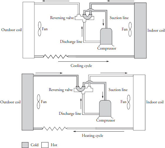
• On heat pump models, check the reversing valve, reversing valve solenoid coil, and thermostats.
• Check for a dirty filter.
• Check for an open fresh air intake or exhaust vent.
• Is the air conditioner the right size for the area?2
• Check for a dirty evaporator coil.
• Check the wiring connections and wiring.
• Check selector switch or electronic control board.
Heat Pump Will Not Go Into Defrost
• Check the defrost control and thermostats.
• Check the reversing valve and solenoid coil.
• Check the wiring connections and wiring.
• Check the electronic control board.
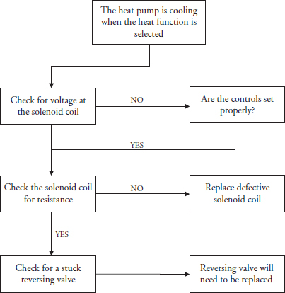
Air Conditioner Is Cooling When the Controls Are Set for Heat
• Check the wiring connections and wiring.
• Check the reversing valve and solenoid coil.
• Check the selector switch or electronic control board.
• Check the thermostats.
Room Air Conditioner Maintenance
Room air conditioners (including portable models) have air filters that need cleaning every 225 to 360 fan-hours of operation. The discharge grille area also needs vacuuming to remove the dust buildup. Twice a year, the following areas need to be inspected and cleaned:
• The evaporator coil
• The condenser coil
• The evaporator pan and base pan
• The indoor blower housing and blower wheel
• All the wiring connections and wiring
• The electrical and mechanical controls
• The voltage at the receptacle
• The inside and outside of the air conditioner
• All gaskets
• The drain system (clean it, too)
• The cabinet seal (clean the outer cabinet)
• The copper tubing
Twice a year you must inspect all control components: electrical and mechanical, electronic, as well as the power supply. The technician must use the proper testing instruments (voltmeter, ohmmeter, ammeter, wattmeter, etc.) to perform electrical tests. The technician should also use an air conditioner or refrigeration thermometer to test the room, outdoor, and coil operating temperatures. Use a sling psychrometer to measure the wet bulb temperatures indoors and outdoors.
When cleaning the air conditioner, use an approved cleaner to wash the unit. Remember to protect the electrical components and fan motor with plastic to prevent the water from damaging the components. Refer to the use and care manual that comes with every air conditioner for further maintenance instructions on the model you are servicing. Do not plug in or run the air conditioner after using water to clean the unit. Wait a few hours, allowing the air conditioner to completely dry out. To prevent electrical mishaps, the air conditioner must be totally dry before you can plug it in.
Performance Data
After you have completed the maintenance or repair on the air conditioner, perform an electrical test by checking the amperage or wattage on the unit, and compare the readings with the information on the model number data tag. At the same time, perform readings on the following:
• The room temperature and outside temperature.
• The temperature differential of the intake and discharge air through the evaporator coil. Take a reliable thermometer, place it in front of the air intake (where the air filter is located), and take a reading. Then place the thermometer in the discharge grille, and take a reading of the air blowing into the room. The difference between the two readings will be the temperature drop. This reading will vary among manufacturers and models. The temperature drop should be between 18 and 31 degrees Fahrenheit.
• The temperature differential of the intake and discharge air through the condenser coil. Use the same reliable thermometer to take the readings.
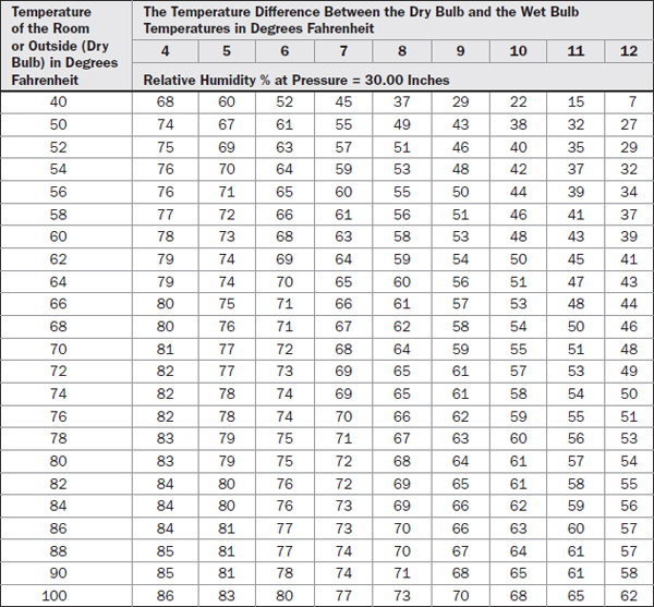
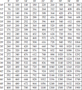
• Use a sling psychrometer to measure the indoor and the outdoor wet bulb temperatures. The sling psychrometer will measure the relative humidity in the room and outside (Table 29-3).
TABLE 29-3 Psychrometric Table. A Wet Bulb Depression Chart. Formula: DB − WB = WDB
• Measure the operating voltage.
• Measure the startup and cycling amperage or wattage of the unit.
Take the readings and match them against the manufacturer’s performance data. You can locate the air conditioner performance data on the manufacturer’s Web site or in the manufacturer’s service manual. The data that you accumulated should match—if it doesn’t, adjustments will have to be made to bring the air conditioner up to manufacturer’s standards. You might have to replace a component, clean the unit, or correct the installation.
Repair Procedures
Each repair procedure is a complete inspection and repair process for a single room air conditioner component. It contains the information you need to test and replace components.
Electronic Components
The electronic components consist of the following: electronic control board, touchpad, and remote control unit.
The typical complaints associated with the electronic components are:
• Unable to program the touchpad panel functions.
• The display board will not display anything.
• Unusual display readouts.
• Unable to control the temperatures.
• The compressor will not run.
• The fan motor will not run.
To prevent electrostatic discharge (ESD) from damaging expensive electronic components, follow the steps in Chapter 11.
To handle these problems, perform the following steps:
1. Verify the complaint. Verify the complaint by operating the air conditioner controls. Turn off the electricity to the air conditioner, and wait for two minutes before turning it back on. If a fault code appears, look up the code. If the air conditioner will not power up, locate the technical data sheet behind the control panel for diagnostics information. It will be helpful if you can locate the actual service manual for the air conditioner model you are working on to properly diagnose the air conditioner. The service manual will assist you in properly placing the air conditioner in the service test mode for testing the air conditioner functions.
2. Check for external factors. You must check for external factors not associated with the air conditioner. Is there electricity to the air conditioner? The voltage at the wall receptacle must be within ±10 percent of the voltage rating on the model and serial data plate. Do you have the correct polarity? (See Chapter 6.) Is the electrical receptacle polarized and properly grounded?
3. Disconnect the electricity. Before working on the air conditioner, disconnect the electricity. This can be done by pulling the plug out of the wall receptacle. Or disconnect the electricity at the fuse panel or circuit breaker panel. Turn off the electricity.
WARNING Some diagnostic tests will require you to test the components with the power turned on. When you disassemble the control panel or remove the outer cabinet, you can position the panel in such a way that the wiring will not make contact with metal. This will allow you to test the components without electrical mishaps.
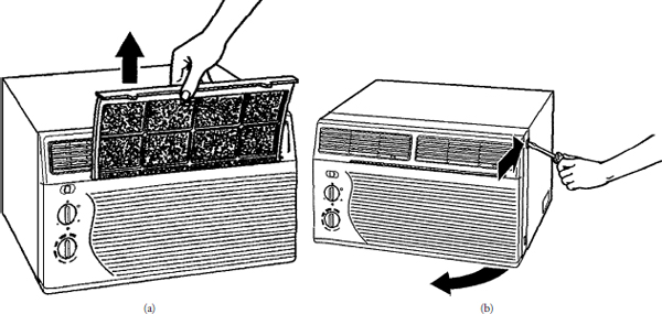
4. Gain access to the electronic components. You can gain access to the electronic components by removing the front grille and the screws on the control panel. Some units have either a one-piece or a two-piece grille with locking tabs and/or screws (Figure 29-5). Be careful not to break the tabs on the grille. On window models, you might have to remove the air conditioner from the window to gain access to the controls. On other models, you should be able to gain access by removing the screws that secure the control panel to the air conditioner frame. Next, tilt the control panel away from the air conditioner, making sure not to pull any of the wires off the controls.
FIGURE 29-5 On some models, the air filter can be removed by sliding it out of the unit or by removing the front grille. Be careful not to damage the tabs on the grille.
WARNING Do not touch the wiring or capacitor until it is discharged.
WARNING A capacitor will hold a charge indefinitely, even when it is not currently in use. A charged capacitor is extremely dangerous. Discharge all capacitors immediately any time that work is being conducted in their vicinity. Redischarge after repowering the equipment if further work must be done. Many capacitors are internally fused. If you are not sure, you can use a 20,000 ohm 2-watt resistor to discharge the capacitor. Do not use a screwdriver to short out the capacitor. By doing so, you will blow out the fuse in the capacitor and the capacitor will not work. Safely use an insulated pair of pliers to remove the wires from the capacitor and place the resistor across the capacitor terminals. When checking a dual capacitor with a capacitor analyzer or ohmmeter, you must test both sides of the capacitor.
5. Test the electronic components. If you are able to run the air conditioner test mode, check the different functions of the air conditioner. Use the technical data sheet for the model you are servicing to locate the test points on the wiring schematic. Check all wiring connections and wiring. Using the technical data sheet, test the electronic control and display board, input voltages, and output voltages.
6. Remove the defective component. To remove the defective component, remove the screws that secure the printed circuit board to the air conditioner frame. Disconnect the connectors from the electronic control board and display.
7. Install the new component. To install a new component, just reverse the disassembly procedure, and reassemble. Reinstall all panels and the front grille, and restore the electricity to the air conditioner. Test the room air conditioner operation. To prevent ESD from damaging expensive electronic components, simply follow the steps in Chapter 11.
Thermistor
The thermistors used in the electronic models plug into the electronic control board, and they monitor the ambient and outdoor temperatures and troubleshooting capabilities.
The typical complaints associated with failure of the thermistor are:
• The air conditioner will not cool or heat.
• Erratic temperature control.
• The air conditioner doesn’t run at all.
To handle these problems, perform the following steps:
1. Verify the complaint. Verify the complaint by checking the control setting. Turn the control to the lowest setting for cool or the highest setting for heat; then turn it back to a normal setting to see if the air conditioner starts cooling or heating. It will be helpful if you can locate the actual service manual for the air conditioner model you are working on to properly diagnose the air conditioner. The service manual will assist you in properly placing the air conditioner in the service test mode for testing the air conditioner functions.
2. Check for external factors. You must check for external factors not associated with the air conditioner. Is the air conditioner installed properly? Is the exhaust or fresh air intake vent open? Explain to the user how to set the controls. The voltage at the wall receptacle must be within ±10 percent of the voltage rating on the model and serial data plate. Do you have the correct polarity? (See Chapter 6.)
3. Disconnect the electricity. Before working on the air conditioner, disconnect the electricity to the unit. This can be done by pulling the plug from the receptacle. Or disconnect the electricity at the fuse panel or at the circuit breaker panel. Turn off the electricity.
WARNING Some diagnostic tests will require you to test the components with the power turned on. When you disassemble the control panel or remove the outer cabinet, you can position the panel in such a way that the wiring will not make contact with metal. This will allow you to test the components without electrical mishaps.
4. Gain access to the thermistor. To access the thermistor, remove the front grille and filter. Some units have either a one-piece or a two-piece grille with locking tabs and/or screws (see Figure 29-5). Be careful not to break the tabs on the grill. On window models, you might have to remove the air conditioner from the window to gain access to the controls. On other models, you should be able to gain access by removing the screws that secure the control panel to the air conditioner frame. Next, tilt the control panel away from the air conditioner, making sure not to pull any of the wires off the controls.
WARNING Do not touch the wiring or capacitor until it is discharged. A capacitor will hold a charge indefinitely, even when it is not currently in use. A charged capacitor is extremely dangerous. Discharge all capacitors immediately any time that work is being conducted in their vicinity. Redischarge after repowering the equipment if further work must be done. Many capacitors are internally fused. If you are not sure, you can use a 20,000 ohm 2-watt resistor to discharge the capacitor. Do not use a screwdriver to short out the capacitor. By doing so, you will blow out the fuse in the capacitor and the capacitor will not work. Safely use an insulated pair of pliers to remove the wires from the capacitor and place the resistor across the capacitor terminals. When checking a dual capacitor with a capacitor analyzer or ohmmeter, you must test both sides of the capacitor.
5. Test the thermistor. The thermistor is attached to the evaporator coil; trace the thermistor wire back to the electronic control board. Disconnect the thermistor connector from the board. Set the ohmmeter on R × 10K, and place the probes on the connector pin terminals. Measure the resistance of the thermistor. Using the technical data sheet, look for the reading and see if the results match. The reading can vary ±10 percent on the chart. Remove the thermistor from the evaporator coil, and submerge the thermistor in ice water for five minutes—the resistance will increase. As the thermistor warms up to ambient temperature, the resistance should return to the original reading. If you suspect an erratic thermistor, replace it with a duplicate of the original.
6. Install a new thermistor. To install the new thermistor, just reverse the order of disassembly, and reassemble. Then test the thermistor. Remember to reinstall the sensor in the same location from which it was removed. If you do not, the air conditioner will not cycle properly.
Thermostat (Operating)
The operating thermostat is located in the control panel. The operating thermostat monitors the ambient room temperature and cycles the air conditioner on and off.
The typical complaints associated with failure of the thermostat are:
• The air conditioner will not cool enough.
• The room or area is too cold.
• The air conditioner runs all the time.
• The air conditioner doesn’t run at all.
To handle these problems, perform the following steps:
1. Verify the complaint. Verify the complaint by checking the control setting. Turn the control to the lowest setting for cool or the highest setting for heat; then turn it back to a normal setting to see if the air conditioner starts cooling or heating. It will be helpful if you can locate the actual service manual for the air conditioner model you are working on to properly diagnose the air conditioner.
2. Check for external factors. You must check for external factors not associated with the air conditioner. Is the air conditioner installed properly? Is the exhaust or fresh air intake vent open? Explain to the user how to set the controls. The voltage at the wall receptacle must be within ±10 percent of the voltage rating on the model and serial data plate. Do you have the correct polarity? (See Chapter 6.)
3. Disconnect the electricity. Before working on the air conditioner, disconnect the electricity to the unit. This can be done by pulling the plug from the receptacle. Or disconnect the electricity at the fuse panel or at the circuit breaker panel. Turn off the electricity.
WARNING Some diagnostic tests will require you to test the components with the power turned on. When you disassemble the control panel or remove the outer cabinet, you can position the panel in such a way that the wiring will not make contact with metal. This will allow you to test the components without electrical mishaps.
4. Gain access to the thermostat. To access the thermostat, remove the front grille and filter. Some units have either a one-piece or a two-piece grille with locking tabs and/or screws (see Figure 29-5). Be careful not to break the tabs on the grille. On window models, you might have to remove the air conditioner from the window to gain access to the controls. On other models, you should be able to gain access by removing the screws that secure the control panel to the air conditioner frame. Next, tilt the control panel away from the air conditioner, making sure not to pull any of the wires off the controls.
WARNING Do not touch the wiring or capacitor until it is discharged. A capacitor will hold a charge indefinitely, even when it is not currently in use. A charged capacitor is extremely dangerous. Discharge all capacitors immediately any time that work is being conducted in their vicinity. Redischarge after repowering the equipment if further work must be done. Many capacitors are internally fused. If you are not sure, you can use a 20,000 ohm 2-watt resistor to discharge the capacitor. Do not use a screwdriver to short out the capacitor. By doing so, you will blow out the fuse in the capacitor and the capacitor will not work. Safely use an insulated pair of pliers to remove the wires from the capacitor and place the resistor across the capacitor terminals. When checking a dual capacitor with a capacitor analyzer or ohmmeter, you must test both sides of the capacitor.
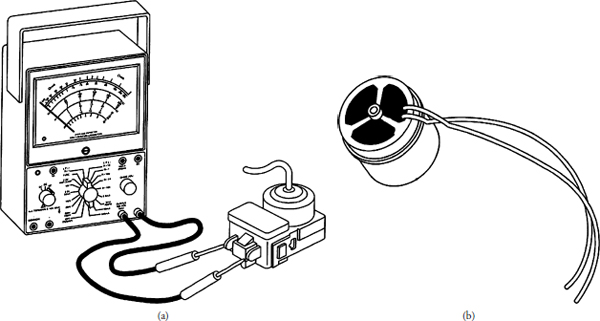
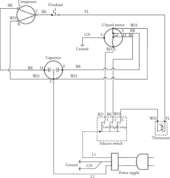
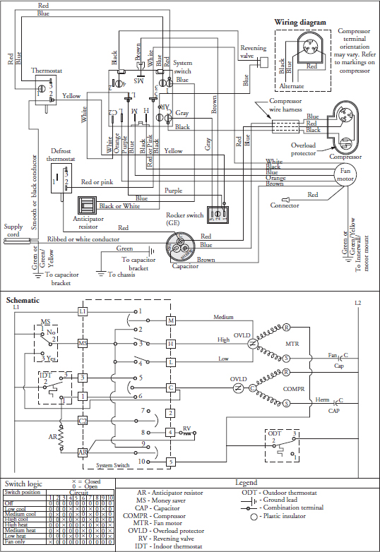
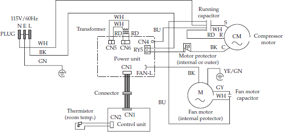
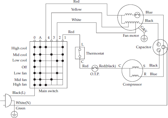
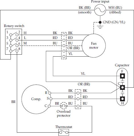
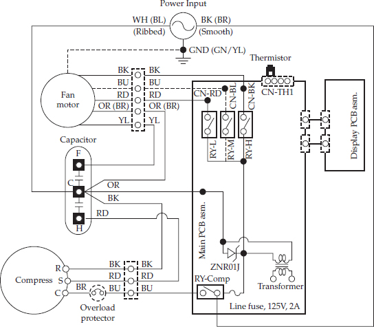
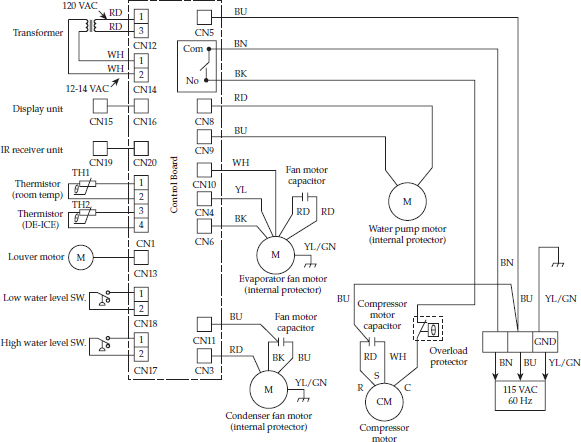
5. Test the thermostat. To test the thermostat, disconnect the wires from the thermostat terminals. On two-wire thermostats, remove the wires from the control, label them, and place the ohmmeter probes on the terminals (Figure 29-6). Set the range scale on R x 1, and test for continuity. With the thermostat set in the warmest (off) position, you should not read continuity. When the thermostat is set to the coldest (highest) position, you should read continuity. Inspect the capillary tube for any damage. If the thermostat capillary tube has lost its charge, the air conditioner will not function properly. For thermostats with more than two terminals (heat models) on the control, you must refer to the wiring diagram on the technical data sheet for the correct terminals to test (Figures 29-7, 29-8, 29-9, 29-10, 29-11, 29-12, 29-13, and 29-14). If the thermostat is good, the problem must be elsewhere.
FIGURE 29-6 (a) Testing the thermostat. (b) Bimetal defrost thermostat.
FIGURE 29-7 A typical wiring schematic for a straight-cool-only air conditioner.
FIGURE 29-8 A typical wiring diagram for a straight-cool air conditioner with electric heat.
FIGURE 29-9 A typical wiring diagram for a straight-cool air conditioner with reverse cycle (heat pump).
FIGURE 29-10 A typical wiring diagram, straight-cool air conditioner with electronic controls.
FIGURE 29-11 A typical wiring diagram, straight-cool air conditioner without electronic controls.
FIGURE 29-12 A typical wiring diagram, straight-cool air conditioner with rotary control.
FIGURE 29-13 A typical wiring diagram for a straight-cool air conditioner with electronic controls.
FIGURE 29-14 A typical wiring diagram for a portable air conditioner.
6. Remove the thermostat. With the thermostat exposed and the wires already removed, the capillary tube must now be removed from the evaporator coil. The capillary tube is held in place on the coil with clips. Remove the capillary tube from the clips. If the clips come off the evaporator coil, remember where the clips go back. The placement of the clips is crucial for the air conditioner to function properly. Now remove the screws that secure the thermostat body to the control panel.
7. Install a new thermostat. To install the new thermostat, just reverse the order of disassembly, and reassemble. Then test the thermostat. Remember to reinstall the capillary tube in the same location from which it was removed. If you do not, the air conditioner will not cycle properly.
Thermostat (Defrost)
The defrost thermostat is only used on heat pump models. On heat pump models with electric heat, this control is a dual-purpose control that acts as an outdoor thermostat and a defrost control. When the thermostat sensing bulb, attached to the condenser coil, senses enough icing on the outdoor coil, it will shut off the compressor and turn on the electric heating element until the outdoor coil temperature reaches above 43 degrees Fahrenheit; then the electric heater will turn off and the air conditioner will resume in the reverse cycle mode (heat). When the outdoor coil temperature drops below 20 degrees Fahrenheit, the air conditioner will operate in electric heat mode continuously until the outdoor coil temperature rises above 43 degrees Fahrenheit. The fan motor will not turn off when defrost occurs, and the reversing four-way valve will not reverse. On models without electric heat, the reversing four-way valve will reverse until the ice has defrosted. Some models use a bimetal type of thermostat, which initiates the defrost cycle.
The typical complaints associated with failure of the defrost thermostat (heat pump models only) are:
• Ice buildup on the outdoor coil.
• The air conditioner will not heat.
To handle these problems, perform the following steps:
1. Verify the complaint. Verify the complaint by checking the control setting. Turn the control to the highest setting for heat, and then turn it back to a normal setting to see if the air conditioner starts heating. It will be helpful if you can locate the actual service manual for the air conditioner model you are working on to properly diagnose the air conditioner.
2. Check for external factors. You must check for external factors not associated with the air conditioner. Is the air conditioner installed properly? Is the exhaust or fresh air intake vent open? Explain to the user how to set the controls. The voltage at the wall receptacle must be within ±10 percent of the voltage rating on the model and serial data plate. Do you have the correct polarity? (See Chapter 6.)
3. Disconnect the electricity. Before working on the air conditioner, disconnect the electricity to the unit. This can be done by pulling the plug from the receptacle. Or disconnect the electricity at the fuse panel or at the circuit breaker panel. Turn off the electricity.
WARNING Some diagnostic tests will require you to test the components with the power turned on. When you disassemble the control panel or remove the outer cabinet, you can position the panel in such a way that the wiring will not make contact with metal. This will allow you to test the components without electrical mishaps.
4. Gain access to the defrost thermostat. To access the defrost thermostat, remove the front grille and filter. Some units have either a one-piece or a two-piece grille with locking tabs and/or screws (see Figure 29-5). Be careful not to break the tabs on the grille. On window models, you might have to remove the air conditioner from the window to gain access to the defrost thermostat. On other models, you should be able to gain access by removing the screws that secure the control panel to the air conditioner frame. Next, tilt the control panel away from the air conditioner, making sure not to pull any of the wires off the controls. Some manufacturers might place the defrost thermostat control behind the bulkhead of the unit. The easiest way to locate that type of control is to follow the capillary tube from the condenser coil to the defrost thermostat body. The defrost thermostat is a nonadjustable thermostat without a stem or knob attached to it. On other models, the defrost thermostat might be a bimetal thermostat that is clamped to the end of the condenser coil with two wires coming out of it that lead back to the control panel.
WARNING Do not touch the wiring or capacitor until it is discharged. A capacitor will hold a charge indefinitely, even when it is not currently in use. A charged capacitor is extremely dangerous. Discharge all capacitors immediately any time that work is being conducted in their vicinity. Redischarge after repowering the equipment if further work must be done. Many capacitors are internally fused. If you are not sure, you can use a 20,000 ohm 2-watt resistor to discharge the capacitor. Do not use a screwdriver to short out the capacitor. By doing so, you will blow out the fuse in the capacitor and the capacitor will not work. Safely use an insulated pair of pliers to remove the wires from the capacitor and place the resistor across the capacitor terminals. When checking a dual capacitor with a capacitor analyzer or ohmmeter, you must test both sides of the capacitor.
5. Test the defrost thermostat. To test the defrost thermostat, disconnect the wires from the defrost thermostat terminals or from the selector control switch, label them, and place the ohmmeter probes on the terminals (see Figure 29-6a). Set the range scale on R x 1, and test the thermostat for continuity. Refer to the technical data sheet for the model you are servicing for the position of the switch contacts (open or closed position in the heat cycle) so that you can get the correct ohmmeter reading. Inspect the capillary tube for any damage. If the thermostat capillary tube has lost its charge, the air conditioner will not function properly. For defrost thermostats with more than two terminals on the control, you must refer to the wiring diagram on the technical data sheet for the correct terminals to test (see Figures 29-7, 29-8, 29-9, 29-10, 29-11, 29-12, 29-13, and 29-14). If the defrost thermostat is good, the problem must be elsewhere.
6. Remove the thermostat. With the thermostat exposed and the wires already removed, the capillary tube must now be removed from the condenser coil. The capillary tube is held in place on the coil with clips. Remove the capillary tube from the clips. If the clips come off the condenser coil, remember where the clips go back. The placement of the clips is crucial for the air conditioner to function properly. Now remove the screws that secure the thermostat body to the control panel. If you are servicing a model that has a bimetal clamp-on defrost thermostat (see Figure 29-6b), remove the clamp that secures the thermostat to the condenser coil. Remember where the thermostat was secured.
7. Install a new thermostat. To install the new defrost thermostat, just reverse the order of disassembly, and reassemble. Then test the defrost thermostat by running the heat cycle. Just remember to reinstall the capillary tube or bimetal clamp in the same location from which it was removed. If you do not, the air conditioner will not cycle properly.
Capacitor
A capacitor is a device that stores electricity to provide an electrical boost for motor starting. Most high-torque motors need a capacitor connected in series with the start winding circuit to produce the desired rotation under a heavy starting load. Some manufacturers will also add a run capacitor in the circuit for motor efficiency.
The typical complaints associated with failure of the capacitor are:
• Fuse is blown or the circuit breaker trips.
• Fan motor will not run.
• Fan motor has a burning smell.
• Motor tries to start and then shuts off on overload.
To handle these problems, perform the following steps:
1. Verify the complaint. Verify the complaint by operating the air conditioner. Listen carefully, and you will hear if there are any unusual noises or if the circuit breaker trips. If you smell something burning, immediately turn off the air conditioner, and pull out the plug. It will be helpful if you can locate the actual service manual for the air conditioner model you are working on to properly diagnose the air conditioner.
2. Check for external factors. You must check for external factors not associated with the air conditioner. Is the air conditioner installed properly? Does it have the correct voltage? The voltage at the wall receptacle must be within ±10 percent of the voltage rating on the model and serial data plate. Do you have the correct polarity? (See Chapter 6.)
3. Disconnect the electricity. Before working on the air conditioner, disconnect the electricity. This can be done by pulling the plug from the electrical outlet. Be sure that you only remove the air conditioner plug. Or disconnect the electricity at the fuse panel or at the circuit breaker panel. Turn off the electricity.
WARNING Some diagnostic tests will require you to test the components with the power turned on. When you disassemble the control panel or remove the outer cabinet, you can position the panel in such a way that the wiring will not make contact with metal. This will allow you to test the components without electrical mishaps.
4. Gain access to the capacitor. Some models have the capacitor mounted on the fan motor; on other models, it is mounted behind the electrical controls. Remove the front grille and filter. Some units have either a one-piece or a two-piece grille with locking tabs and/or screws (see Figure 29-5). Be careful not to break the tabs on the grille. On window models, you might have to remove the air conditioner from the window to gain access to the controls. On other models, you should be able to gain access by removing the screws that secure the control panel to the air conditioner frame. Next, tilt the control panel away from the air conditioner, making sure not to pull any of the wires off the controls.
WARNING Do not touch the wiring or capacitor until it is discharged. A capacitor will hold a charge indefinitely, even when it is not currently in use. A charged capacitor is extremely dangerous. Discharge all capacitors immediately any time that work is being conducted in their vicinity. Redischarge after repowering the equipment if further work must be done.
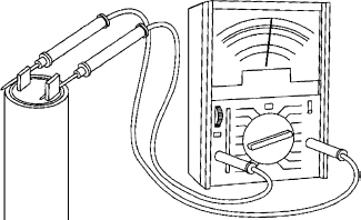
5. Test the capacitor. Many capacitors are internally fused. If you are not sure, you can use a 20,000 ohm 2-watt resistor to discharge the capacitor. Do not use a screwdriver to short out the capacitor. By doing so, you will blow out the fuse in the capacitor and the capacitor will not work. Safely use an insulated pair of pliers to remove the wires from the capacitor and place the resistor across the capacitor terminals. When checking a dual capacitor with a capacitor analyzer or ohmmeter, you must test both sides of the capacitor. Set the ohmmeter on the highest scale, and then place one probe on one terminal and the other probe on the other terminal (Figure 29-15). Observe the meter action. While the capacitor is charging, the ohmmeter will read nearly zero ohms for a short period of time. Then the ohmmeter reading will slowly return toward infinity. If the ohmmeter reading deflects to zero and does not return to infinity, the capacitor is shorted and should be replaced. If the ohmmeter reading remains at infinity and does not dip toward zero, the capacitor is open and should be replaced.
FIGURE 29-15 Testing a capacitor for an open or short circuit.
To test for a grounded capacitor, leave one meter probe on the capacitor terminal, and attach the other probe to the outer casing of the capacitor or air conditioner chassis ground. There should be no reading if the capacitor is not grounded. Next, remove the probe from the capacitor terminal, and place the probe on the other terminal. Again, there should be no reading indicated if the capacitor is not grounded.3
When using a capacitor analyzer to test capacitors, it will show whether the capacitor is “open” or “shorted.” It will tell whether the capacitor is within its microfarads rating, and it will show whether the capacitor is operating at the proper power-factor percentage. The instrument will automatically discharge the capacitor when the test switch is released.
6. Remove the capacitor. Remove the capacitor from its mounting bracket.
7. Install a new capacitor. To install the new capacitor, just reverse the disassembly procedure, and reassemble.
NOTE A capacitor is rated by its working voltage (WV or WVac) and by its storage capacity in microfarads (µF). Always replace a capacitor with one that has the same voltage rating and the same (or up to 10 percent greater) microfarad rating.
Fan Motor
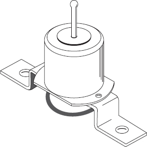
Most air conditioner models use a single fan motor with a double shaft for the fan blade and blower wheel. There are some models that use two fan motors, powered by AC or DC volts. Review the wiring diagram to see what type of motor(s) you are dealing with.
The typical complaints associated with failure of the fan motor are:
• No air is blowing out of the discharge grille.
• There is no cooling or heating.
• When the motor runs, there are loud noises.
• The fuse or circuit breaker trips when the air conditioner is started.
To handle these problems, perform the following steps:
1. Verify the complaint. Verify the complaint by operating the air conditioner. Listen carefully, and you will hear if there are any unusual noises or if the circuit breaker trips. It will be helpful if you can locate the actual service manual for the air conditioner model you are working on to properly diagnose the air conditioner.
2. Check for external factors. You must check for external factors not associated with the air conditioner. Is the air conditioner installed properly? Does it have the correct voltage? The voltage at the wall receptacle must be within ±10 percent of the voltage rating on the model and serial data plate. Do you have the correct polarity? (See Chapter 6.)
3. Disconnect the electricity. Before working on the air conditioner, disconnect the electricity. This can be done by pulling the plug out of the wall receptacle. Be sure that you only remove the air conditioner plug. Or disconnect the electricity at the fuse panel or at the circuit breaker panel. Turn off the electricity.
WARNING Some diagnostic tests will require you to test the components with the power turned on. When you disassemble the control panel or remove the outer cabinet, you can position the panel in such a way that the wiring will not make contact with metal. This will allow you to test the components without electrical mishaps.
4. Gain access to the fan motor. Before you begin to remove the fan motor, test the motor windings. Remove the front grille and filter. Some units have either a one-piece or a two-piece grille with locking tabs and/or screws (see Figure 29-5). Be careful not to break the tabs on the grille. On window models, you might have to remove the air conditioner from the window to gain access to the controls. On other models, you should be able to gain access by removing the screws that secure the control panel to the air conditioner frame. Next, tilt the control panel away from the air conditioner, making sure not to pull any of the wires off the controls.
WARNING Do not touch the wiring or capacitor until it is discharged. A capacitor will hold a charge indefinitely, even when it is not currently in use. A charged capacitor is extremely dangerous. Discharge all capacitors immediately any time that work is being conducted in their vicinity. Redischarge after repowering the equipment if further work must be done. Many capacitors are internally fused. If you are not sure, you can use a 20,000 ohm 2-watt resistor to discharge the capacitor. Do not use a screwdriver to short out the capacitor. By doing so, you will blow out the fuse in the capacitor and the capacitor will not work. Safely use an insulated pair of pliers to remove the wires from the capacitor and place the resistor across the capacitor terminals. When checking a dual capacitor with a capacitor analyzer or ohmmeter, you must test both sides of the capacitor.
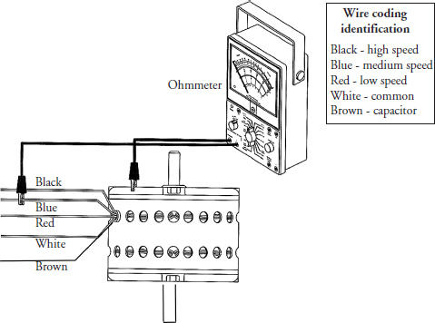
5. Disconnect the motor wire leads. Disconnect the motor wire leads from the selector switch, and label them. Check the motor windings for continuity (Figure 29-16). Check for resistance from the common wire lead (white) to the high-speed (black) wire lead (Figure 29-16a). Then check the resistance from the common wire lead (white) to the medium-speed (blue) and the common wire lead (white) to the low-speed (red) winding (Figures 29-16b and 29-16c). If the fan motor has a capacitor wire (brown), check for resistance from the brown wire lead to the common wire lead (white).4 To check for a grounded winding in the motor, take the ohmmeter probes and check from each motor wire lead to the motor housing (Figure 29-17). The ohmmeter will indicate continuity if the windings are grounded.
FIGURE 29-16 (a) Check from the common winding to the high-speed winding. (b) Check from the common winding to the medium-speed winding. (c) Check from the common winding to the low-speed winding.
FIGURE 29-17 Checking for a grounded motor.
Finally, spin the motor shaft—it should turn freely. If the shaft is hard to turn, replace the fan motor. Now move the motor shaft in an up-and-down motion perpendicular to the motor body. The shaft should have virtually no movement. If there is a lot of play in the end bell bearings, replace the fan motor.5
6. Remove the fan motor. To remove the fan motor, the air conditioner will have to be uninstalled or the chassis slid out of the outer case and placed on a solid table or workbench.
WARNING This procedure will require two people to uninstall and move the air conditioner.
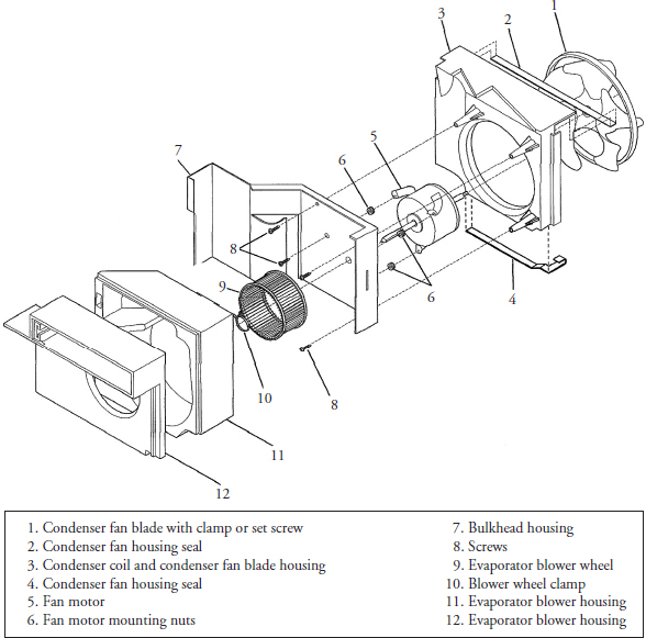
Depending on which model you are servicing, the removal of the fan motor will vary from manufacturer to manufacturer. However, the basic steps are the same for every air conditioner: The fan motor is secured to the bulkhead (Figure 29-18). In order to remove it, you must first remove the condenser fan blade. To gain access to the fan blade, remove the screws and brackets6 that secure the condenser coil to the fan shroud. On some models, the upper housing has a cover—remove it. The condenser coil will have to be lifted up out of the base pan and gently moved out of the way to gain access to the fan blade. You only have to move the condenser coil enough to gain access to the fan blade and to provide room to remove the fan blade without damaging the condenser coil.
FIGURE 29-18 An exploded view of the fan motor, condenser fan blade, blower wheel, and the housings.
WARNING When moving the condenser coil away from the fan blade, do not kink or break the copper tubing. Remember that there is high-pressure refrigerant in the lines.
Remove the setscrew or clamp from the condenser fan blade. When removing the fan blade, be careful not bend or damage it. To gain access to the evaporator blower wheel (see Figure 29-18), remove the screws from the evaporator blower housing, exposing the blower wheel. Depending on which model you are servicing, you may have to remove part of the housing to gain access. Next, remove the clamp from the blower wheel. You will not be able to remove the blower wheel at this time until the fan motor is removed from the bulkhead. With the condenser fan blade removed and the evaporator blower wheel loose on the motor shaft, you are now ready to remove the motor. Remove the fan motor wiring from the control area, making sure to free up the fan motor wiring harness that may be secured to the chassis. Now remove the fan motor nuts or bolts that secure the fan motor to the bulkhead. Grab hold of the fan motor, and pull it out of the air conditioner while removing the evaporator blower wheel from the motor shaft. The blower wheel will remain in the evaporator blower housing.
NOTE Replace the fan motor with a duplicate of the original for easier installation. With the fan motor removed from the unit, it is the perfect time to chemically clean the remainder of the air conditioner. Everything will be exposed, and it will be easier to clean the unit.
7. Reinstall the fan motor. To reinstall the fan motor, just reverse the instructions in step 6, and reassemble. When you reinstall the condenser fan blade, make sure to place it back on the motor shaft in the same position. Most room air conditioner condenser fan blades have a slinger ring that is attached to the paddles. The slinger ring will sit in a sump area in the base pan, allowing the fan blade to pick up the condensate water, flinging it against the condenser coil. Before reinstalling the outer cabinet or installing the air conditioner in the wall, test the air conditioner first. Make sure the fan blade and the blower wheel are not hitting against anything.
Compressor and Overload Protector
The compressor (reciprocating or rotary type) is the heart of the vapor compression refrigeration system. It is used to circulate the refrigerant throughout the sealed system. The overload is attached to the compressor housing and protects the compressor.
The typical complaints associated with failure of the compressor are:
• The air conditioner will not cool.
• The room temperature is warm.
• The air conditioner does not run at all.
• The compressor makes a humming or buzzing noise and stops.
• The circuit breaker trips when the air conditioner starts up.
To handle these problems, perform the following steps:
1. Verify the complaint. Verify the complaint by asking the customer to describe what the air conditioner is doing. It will be helpful if you can locate the actual service manual for the air conditioner model you are working on to properly diagnose the air conditioner.
2. Check for external factors. You must check for external factors not associated with the air conditioner. Is the air conditioner installed properly? Does it have the correct voltage? Check for a voltage drop during air conditioner startup. The voltage at the wall receptacle must be within ±10 percent of the voltage rating on the model and serial data plate. Do you have the correct polarity? (See Chapter 6.)
3. Disconnect the electricity. Before working on the air conditioner, disconnect the electricity. This can be done by pulling the plug from the receptacle. Or disconnect the electricity at the fuse panel or at the circuit breaker panel. Turn off the electricity.
WARNING Before you begin to service any high-voltage components within the air conditioner, you must discharge the high-voltage capacitors first.
WARNING A capacitor will hold a charge indefinitely, even when it is not currently in use. A charged capacitor is extremely dangerous. Discharge all capacitors immediately any time that work is being conducted in their vicinity. Redischarge after repowering the equipment if further work must be done. Many capacitors are internally fused. If you are not sure, you can use a 20,000 ohm 2-watt resistor to discharge the capacitor. Do not use a screwdriver to short out the capacitor. By doing so, you will blow out the fuse in the capacitor and the capacitor will not work. Safely use an insulated pair of pliers to remove the wires from the capacitor and place the resistor across the capacitor terminals. When checking a dual capacitor with a capacitor analyzer or ohmmeter, you must test both sides of the capacitor.
WARNING Some diagnostic tests will require you to test the components with the power turned on. When you disassemble the control panel or remove the outer cabinet, you can position the panel in such a way that the wiring will not make contact with metal. This will allow you to test the components without electrical mishaps.
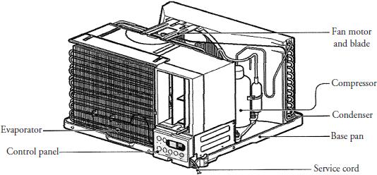
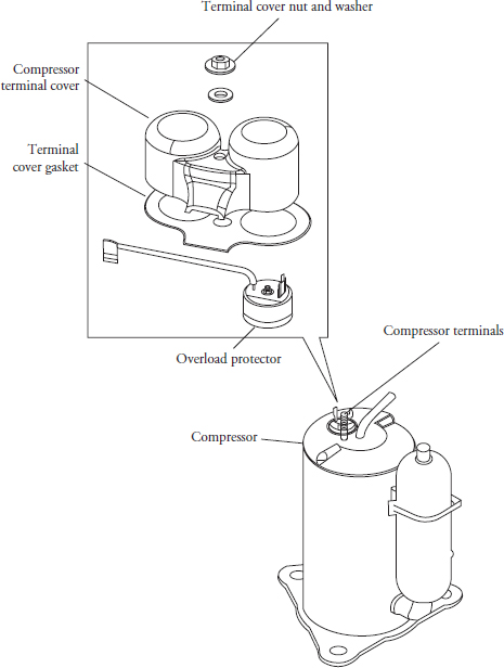
4. Gain access to the compressor. To access the compressor, pull the air conditioner out and away from the window or wall. Remove the outer cabinet (on some models). This will expose the compressor, fan motor, and electrical controls (Figure 29-19). Next, remove the compressor terminal cover (Figure 29-20) by removing the retaining nut or clip that secures the cover. Remove the terminal cover and washer.
FIGURE 29-19 An illustration of the component location on a slide-out chassis wall air conditioner.
FIGURE 29-20 An exploded view of a rotary compressor, overload protector, and terminal cover.
5. Test the overload protector. To test the overload protector, remove the wires from the overload and compressor terminals. Next, place the probes of the ohmmeter on the overload terminals (see Figure 29-20). Set the meter scale on R x 1. The reading will show continuity. If not, replace the overload protector.
6. Test the compressor. The compressor terminals are marked C, S, and R: C indicates the common winding terminal, S indicates the start winding terminal, and R indicates the run winding terminal. Refer to the wiring diagram for the model that you are servicing. Set the meter scale on R × 1, touch the probes together, and adjust the needle setting to indicate a zero reading. Next, place the probes of the ohmmeter on the terminals marked S and R (see Figure 25-37a). The meter reading will show continuity. Now place the meter probes on the terminals marked C and S. The meter reading will show continuity. Finally, place the meter probes on the terminals marked C and R. The meter reading will show continuity. The total number of ohms measured between S and R is equal to the sum of C to S plus C to R. The compressor should be tested for proper resistance, as indicated on the wiring diagram.
To test the compressor for ground, place one probe on a compressor terminal, and attach the other probe to the compressor housing or to any good ground (see Figure 25-37b). Set the meter scale to R x 1000. The meter reading will show no continuity. Repeat this for the remaining two terminals. The meter reading will show no continuity. If you get a continuity reading from any of these terminals to ground, the compressor is grounded. Replace it.
WARNING This procedure may require two people to uninstall and move the air conditioner.
Electric Heater Element
Air conditioner heating elements are made with a nickel-chromium wire, having both tensile strength and high resistance to current flow. The resistance and voltage can be measured with a multimeter to verify if the element is functioning properly. Some manufacturers are also using calrod heaters instead of nickel-chromium wire heaters. This type of heater can be tested for resistance and voltage, too.
The typical complaint associated with failure of the electric heater element is that the air conditioner will not heat at all. To handle this problem, perform the following steps:
1. Verify the complaint. Verify the complaint by checking the control setting. Turn the control to the highest setting for heat; then turn it back to a normal setting to see if the air conditioner starts heating. It will be helpful if you can locate the actual service manual for the air conditioner model you are working on to properly diagnose the air conditioner.
2. Check for external factors. You must check for external factors not associated with the air conditioner. Is the air conditioner installed properly? Is the exhaust or fresh air intake vent open? Check for the correct voltage to the air conditioner. The voltage at the wall receptacle must be within ±10 percent of the voltage rating on the model and serial data plate. Do you have the correct polarity? (See Chapter 6.) Explain to the user how to set the controls.
3. Disconnect the electricity. Before working on the air conditioner, disconnect the electricity to the unit. This can be done by pulling the plug from the receptacle. Or disconnect the electricity at the fuse panel or at the circuit breaker panel. Turn off the electricity.
WARNING Some diagnostic tests will require you to test the components with the power turned on. When you disassemble the control panel or remove the outer cabinet, you can position the panel in such a way that the wiring will not make contact with metal. This will allow you to test the components without electrical mishaps.
4. Gain access to the electric heater element circuitry. To access the electric heater element circuitry, remove the front grille and filter. Some units have either a one-piece or a two-piece grill with locking tabs and/or screws (see Figure 29-5). Be careful not to break the tabs on the grill. On window models, you might have to remove the air conditioner from the window to gain access to the controls. On other models, you should be able to gain access by removing the screws that secure the control panel to the air conditioner frame. Next, tilt the control panel away from the air conditioner, making sure not to pull any of the wires off the controls.
WARNING Do not touch the wiring or capacitor until it is discharged. A capacitor will hold a charge indefinitely, even when it is not currently in use. A charged capacitor is extremely dangerous. Discharge all capacitors immediately any time that work is being conducted in their vicinity. Redischarge after repowering the equipment if further work must be done. Many capacitors are internally fused. If you are not sure, you can use a 20,000 ohm 2-watt resistor to discharge the capacitor. Do not use a screwdriver to short out the capacitor. By doing so, you will blow out the fuse in the capacitor and the capacitor will not work. Safely use an insulated pair of pliers to remove the wires from the capacitor and place the resistor across the capacitor terminals. When checking a dual capacitor with a capacitor analyzer or ohmmeter, you must test both sides of the capacitor.
5. Test the electric heater element. At this point, you do not have to disassemble the air conditioner to determine if the electric heater element is defective. Locate the wiring diagram (see Figure 29-8), and trace the electric heater element circuit. You will notice that the heater element, thermal fuse, and heater limit control (thermostat) are wired in series with the selector switch and operating thermostat. These five components make up the heating circuit. Locate the electric heater element wiring, and disconnect the wires from the terminals. For example, in the wiring diagram shown in Figure 29-8, the orange and red wires from the electric heater element go to the capacitor common terminal and to the number 4 terminal on the selector switch. If you remove those two wires from their terminals, you have just isolated the electric heater element, thermal fuse, and the heater limit control. Set your ohmmeter to the R x 1 scale, and check for continuity between those two wires.7 If the ohmmeter reads resistance in the circuit, then the problem is elsewhere. If your ohmmeter reads an open circuit, you will have to remove the electric heater assembly for further testing.
6. Remove the electric heater assembly. The electric heater assembly is located in the evaporator blower housing on the discharge side. It may be behind a metal screen on older models. For newer models, the heater element is located behind the evaporator coil. To remove the heater assembly, the air conditioner will have to be uninstalled.
WARNING This procedure may require two people to uninstall and move the air conditioner.
Remove the screws that secure the top panel on the evaporator blower housing (see Figure 29-18). On some models, part of the evaporator housing can be removed for easy access to the heater assembly. Once you gain access to the heater assembly, remove the screws that secure the assembly to the air conditioner. Replace with a duplicate of the original.
NOTE With the electric heater assembly removed from the unit, it is the perfect time to chemically clean the remainder of the air conditioner. Everything will be exposed, and it will be easier to clean the unit. Just remember to protect the electrical components and fan motor.
7. Install the heater assembly. To install a new electric heater assembly, just reverse the disassembly procedure, and reassemble. Reinstall all panels and the front grille, and restore the electricity to the air conditioner. Test the room air conditioner heat operation.
Reversing Valve Solenoid Coil
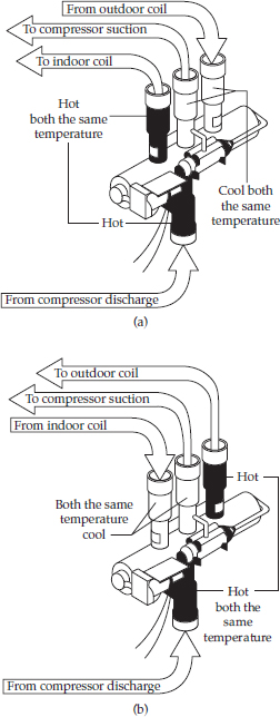
A reversing valve solenoid is a device used to convert electrical energy into mechanical energy. When the solenoid is energized, it acts like an electromagnet and is positioned to move a predesignated metal object within the reversing valve.
The typical complaint associated with failure of the reversing valve solenoid coil is that the air conditioner will not heat. To handle this problem, perform the following steps:
1. Verify the complaint. Verify the complaint by checking the control setting. Turn the control to the lowest setting for cool or the highest setting for heat; then turn it back to a normal setting to see if the air conditioner starts cooling or heating. It will be helpful if you can locate the actual service manual for the air conditioner model you are working on to properly diagnose the air conditioner.
2. Check for external factors. You must check for external factors not associated with the air conditioner. Is the air conditioner installed properly? Is the exhaust or fresh air intake vent open? Explain to the user how to set the controls. The voltage at the wall receptacle must be within ±10 percent of the voltage rating on the model and serial data plate. Do you have the correct polarity? (See Chapter 6.)
3. Disconnect the electricity. Before working on the air conditioner, disconnect the electricity to the unit. This can be done by pulling the plug from the receptacle. Or disconnect the electricity at the fuse panel or at the circuit breaker panel. Turn off the electricity.
WARNING Some diagnostic tests will require you to test the components with the power turned on. When you disassemble the control panel or remove the outer cabinet, you can position the panel in such a way that the wiring will not make contact with metal. This will allow you to test the components without electrical mishaps.
4. Gain access to the reversing valve solenoid coil. To access the reversing valve solenoid coil wiring, remove the front grille and filter. Some units have either a one-piece or a two-piece grill with locking tabs and/or screws (see Figure 29-5). Be careful not to break the tabs on the grille. On window models, you might have to remove the air conditioner from the window to gain access to the controls. On other models, you should be able to gain access by removing the screws that secure the control panel to the air conditioner frame. Next, tilt the control panel away from the air conditioner, making sure not to pull any of the wires off the controls.
WARNING Do not touch the wiring or capacitor until it is discharged. A capacitor will hold a charge indefinitely, even when it is not currently in use. A charged capacitor is extremely dangerous. Discharge all capacitors immediately any time that work is being conducted in their vicinity. Redischarge after repowering the equipment if further work must be done. Many capacitors are internally fused. If you are not sure, you can use a 20,000 ohm 2-watt resistor to discharge the capacitor. Do not use a screwdriver to short out the capacitor. By doing so, you will blow out the fuse in the capacitor and the capacitor will not work. Safely use an insulated pair of pliers to remove the wires from the capacitor and place the resistor across the capacitor terminals. When checking a dual capacitor with a capacitor analyzer or ohmmeter, you must test both sides of the capacitor.
5. Test the reversing valve solenoid coil. To test the solenoid coil, disconnect the wires from the selector switch terminals. Look on the wiring diagram for the correct wires to remove. Set the ohmmeter on the R x 10K scale, and place the meter probes on the solenoid coil wire terminals. You should read resistance in the coil. If not, replace the solenoid coil with a duplicate of the original.
6. Replace the reversing valve solenoid coil. To access the solenoid coil, pull the air conditioner out and away from the window or wall. Remove the outer cabinet (on some models). This will expose the compressor, reversing valve, fan motor, and electrical controls (see Figure 29-19). The reversing valve is located near the compressor. Remove the retaining nut and washer from the pilot valve stem on the reversing valve, and remove the solenoid coil.
7. Install the reversing valve solenoid coil. To install a new solenoid coil, just reverse the disassembly procedure, and reassemble. Reinstall all panels and the front grille, and restore the electricity to the air conditioner. Test the room air conditioner heat operation.
Selector Switch
The selector switch is mounted in the control panel. Its main purpose is to select which cycle to run—for example: heat, cool, or fan only.
The typical complaints associated with failure of the selector switch are:
• The air conditioner will not cool or heat.
• The air conditioner doesn’t run at all.
To handle these problems, perform the following steps:
1. Verify the complaint. Verify the complaint by checking the control setting to see if the air conditioner starts cooling or heating. It will be helpful if you can locate the actual service manual for the air conditioner model you are working on to properly diagnose the air conditioner.
2. Check for external factors. You must check for external factors not associated with the air conditioner. Is the air conditioner installed properly? Is the exhaust or fresh air intake vent open? Is the voltage correct to the air conditioner? The voltage at the wall receptacle must be within ±10 percent of the voltage rating on the model and serial data plate. Do you have the correct polarity? (See Chapter 6.) Explain to the user how to set the controls.
3. Disconnect the electricity. Before working on the air conditioner, disconnect the electricity to the unit. This can be done by pulling the plug from the receptacle. Or disconnect the electricity at the fuse panel or at the circuit breaker panel. Turn off the electricity.
WARNING Some diagnostic tests will require you to test the components with the power turned on. When you disassemble the control panel or remove the outer cabinet, you can position the panel in such a way that the wiring will not make contact with metal. This will allow you to test the components without electrical mishaps.
4. Gain access to the selector switch. To access the selector switch, remove the front grille and filter. Some units have either a one-piece or a two-piece grill with locking tabs and/or screws (see Figure 29-5). Be careful not to break the tabs on the grille. On window models, you might have to remove the air conditioner from the window to gain access to the controls. On other models, you should be able to gain access by removing the screws that secure the control panel to the air conditioner frame. Next, tilt the control panel away from the air conditioner, making sure not to pull any of the wires off the controls.
WARNING Do not touch the wiring or capacitor until it is discharged. A capacitor will hold a charge indefinitely, even when it is not currently in use. A charged capacitor is extremely dangerous. Discharge all capacitors immediately any time that work is being conducted in their vicinity. Redischarge after repowering the equipment if further work must be done. Many capacitors are internally fused. If you are not sure, you can use a 20,000 ohm 2-watt resistor to discharge the capacitor. Do not use a screwdriver to short out the capacitor. By doing so, you will blow out the fuse in the capacitor and the capacitor will not work. Safely use an insulated pair of pliers to remove the wires from the capacitor and place the resistor across the capacitor terminals. When checking a dual capacitor with a capacitor analyzer or ohmmeter, you must test both sides of the capacitor.
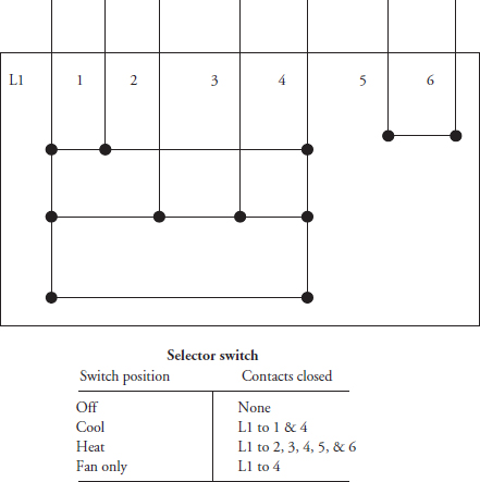
5. Test the selector switch. To test the selector switch, locate the selector switch circuit on the wiring diagram (see Figures 29-7, 29-8 29-9 29-10, 29-11, 29-12, 29-13, and 29-14). Identify the terminals that turn on the different components to be tested. Only remove those wires for the switch contacts you are testing. Set the ohmmeter on the R x 1 scale. Next, place the ohmmeter probes on those terminals. Then select the setting by either rotating the dial or by pressing the proper button on the switch (Figure 29-21). If the switch contacts are good, your meter will show continuity. Test all of the remaining component settings on the selector switch. Remember to check the wiring diagram for the correct switch contact terminals (those that correspond to the setting that you are testing).
FIGURE 29-21 The selector switch contact test points.
6. Remove the selector switch. To remove the selector switch, remove all of the wires from the switch and label them, remove the screws that hold the switch to the control panel, and remove the switch.
7. Install the new selector switch. To install the new selector switch, just reverse the disassembly procedure, and reassemble. Then reattach the wires to the switch terminals according to the wiring diagram. Reassemble the control panel. When you are reassembling the control panel, make sure that the wires do not become pinched between the control panel and the air conditioner frame.
Troubleshooting Sealed-System Problems
If you suspect a sealed-system malfunction, be sure to check out all external factors first. These include:
• Thermostats
• Compressor
• Overload on the compressor
• Fan motor
• Evaporator and condenser coils getting good air circulation
• Air conditioner installation
• Make sure the heater is not on at the same time as cooling
• Make sure that the reversing valve and solenoid coil are operating properly
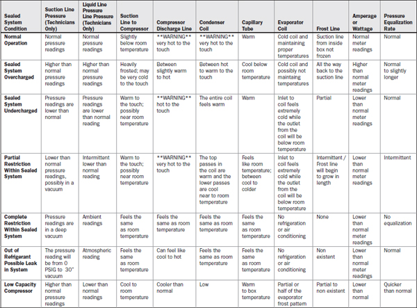
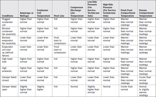
After eliminating all of these external factors, you will then systematically check the sealed system. This is accomplished by comparing the conditions found in a normally operating air conditioner. These conditions are:
• Room temperature
• Wattage
• Condenser temperature
• Evaporator inlet sound (gurgle, hiss, etc.)
• Evaporator cooling pattern
• Pressure equalization time
One thing to keep in mind: No single indicator is conclusive proof that a particular sealed-system problem exists. Rather, a combination of findings must be used to definitively pinpoint the exact problem.
Low-Capacity Compressor
Symptoms of a low-capacity compressor in the sealed system are:
• Temperatures in the room or area will be above normal.
• The wattage and amperage will be below normal, as indicated on the model/serial plate.
• The temperature of the condenser coil will be below normal.
• At the evaporator coil, you will hear a slightly reduced gurgling noise.
• The evaporator coil will show a normal cooling pattern.
• The high-side pressure will be below normal, and the low-side pressure will be above normal.8
• The pressure equalization time might be normal or shorter than normal.
Refrigerant Leak
Symptoms of a refrigerant leak in the sealed system are:
• Temperatures in the room or area will be below normal.
• The wattage and amperage will be below normal, as indicated on the model/serial plate.
• The condenser coil will be cool to the touch at the last pass, or even as far as midway through the coil.
• At the evaporator coil, you will hear a gurgling noise, a hissing noise, or possibly an intermittent hissing or gurgling noise.
• The evaporator coil will show a frost pattern in the lower rungs of the coil.
• The high- and low-side pressures will be below normal.8
• The pressure equalization time might be normal or shorter than normal.
Overcharged Air Conditioner
If the sealed system is overcharged, the symptoms are:
• The room temperature will be higher than normal.
• The wattage and amperage will be above normal, as indicated on the model/ serial plate.
• The temperature of the condenser coil will be above normal.
• At the evaporator coil, you will hear a constant gurgling noise—generally, a higher sound level than normal.
• The evaporator coil will show a full frost pattern. If you remove the cover, you will possibly see the suction line frosted back to the compressor.
• The high- and low-side pressures will be above normal.8
• The pressure equalization time will be normal.
Slight Restriction
Symptoms of a slight restriction in the sealed system are:
• The room temperature will be below normal.
• The wattage and amperage will be below normal, as indicated on the model/ serial plate.
• The temperature of the condenser coil will be slightly below normal.
• At the evaporator coil, you will hear a constant gurgling noise and a low sound level.
• The evaporator coil cooling pattern will be receded.
• The high- and low-side pressures will be below normal.8
• The pressure equalization time will be longer than normal.
Partial Restriction
Symptoms of a partial restriction in the sealed system are:
• The room temperature will be higher than normal.
• The wattage and amperage will be below normal, as indicated on the model/serial plate.
• The temperature of the condenser coil will be below normal more than halfway on the coil.
• At the evaporator coil, you will hear a constant gurgling noise and a considerably lower sound level.
• The evaporator coil cooling pattern will be considerably receded.
• The high- and low-side pressures will be below normal.8
• The pressure equalization time will be longer than normal.
Complete Restriction
Symptoms of a complete restriction in the sealed system are:
• The room temperature will be warm.
• The wattage and amperage will be considerably below normal, as indicated on the model/serial plate.
• The temperature of the condenser coil will be cool or at room temperature.
• At the evaporator coil, you will hear no sounds.
• The evaporator coil will not be cool.
• The high-side pressure will be equal to the pressure of refrigerant at room temperature.
• The low-side pressure will be in a deep vacuum.8
• There will be no pressure equalization time.
Moisture Restriction
Symptoms of a moisture restriction in the sealed system are:
• The room temperature will be above normal.
• The wattage and amperage will be considerably below normal, as indicated on the model/serial plate.
• The temperature of the condenser coil will be below normal.
• At the evaporator coil, you will hear a constant gurgle, low sound level, or no sound at all.
• The evaporator coil might have some frost on the evaporator inlet.
• The high-side pressure will be below normal.8
• The low-side pressure will be below normal or in a deep vacuum.8
• The pressure equalization time will be longer than normal or there will be no equalization at all.
Reversing Valve (Heat Pump Models)
In a straight-cool air conditioner, the refrigerant flows from the compressor discharge through the condenser coil, capillary tube, evaporator coil, and back through the suction line to the compressor. The ability of an air conditioner to reverse the direction of the refrigerant flow is achieved with a reversing valve installed in the refrigerant circuit. The reversing valve is designed as a single-port, double-throw valve. It turns the function of the evaporator coil from a heat absorption coil into a heat dissipation coil (condenser coil) (Figure 29-22). When the solenoid coil is energized, the valve will reverse the refrigerant flow. For cooling, in a heat-pump air conditioner, the refrigerant flows from the compressor discharge through the reversing valve to the outdoor coil, through the capillary tube and indoor coil, and back through the reversing valve to the suction port on the compressor. For heating, the refrigerant will flow from the compressor discharge, through the reversing valve, indoor coil, capillary tube, and outdoor coil, and then back through the reversing valve to the suction port on the compressor (Figures 29-23 and 29-24).
FIGURE 29-22 The refrigerant flow in a reverse-cycle valve. (a) The reversing valve solenoid coil is de-energized in the cooling mode. (b) The reversing valve solenoid coil is energized in the heating mode.
FIGURE 29-23 The refrigerant flow in a heat pump for cooling and heating.
FIGURE 29-24 (a) Illustrates the reversing valve in the heating mode. (b) Illustrates the reversing valve in the cooling mode. The reversing valve is also known as a four-way valve.
The reversing valve itself is a non-serviceable component and must be replaced with a duplicate of the original if it fails. It is recommended that a qualified technician with refrigerant certification replace the reversing valve. The refrigerant in the sealed system must be recovered properly.
Diagnostic Charts
The following diagnostic flowcharts, tables, and wiring diagrams will help you to pinpoint the likely causes of problems with room air conditioners (see Tables 29-4, 29-5, and 29-6 and Figures 29-7, 29-8, 29-9, 29-10, 29-11, 29-12, 29-13, 29-14, 29-25, and 29-26).
TABLE 29-4 Reversing Valve Touch Test Chart
TABLE 29-5 Refrigeration Sealed System Diagnosis Chart
TABLE 29-6 Conditions That Will Mimic Sealed System Failures
FIGURE 29-25 The diagnostic flowchart: The air conditioner is cooling when the heat function is selected.
FIGURE 29-26 The diagnostic flowchart: Air conditioner will not heat or cool.
Cooling Capacity
Using the charts in Figures 29-27 and 29-8, follow the guidelines listed here to choose the correct size air conditioner.
FIGURE 29-27 Floor area table.
1. Use the chart in Figure 29-27 to determine the square footage of the area to be cooled. If the room to be cooled is next to an adjacent area to be cooled, this will count as two areas. Determine the square footage of each area and then add the two totals.
2. Locate the square footage on the left or right side of the cooling capacity chart (Figure 29-28), and then draw a horizontal line across the chart. Select the correct air conditioner capacity from one of the three diagonal bands on the chart, and then go straight down the chart to the correct daytime cooling capacity BTU/hr.
FIGURE 29-28 Air conditioner sizing chart. If the area to be cooled includes a kitchen area, add 4000 BTU/hr. If more than two people occupy the area, add 600 BTU/hr per person. If only one person occupies the area, then subtract 600 BTU/hr.
The diagonal bands on the chart help compensate for variations in cooling applications. The bands indicate a range of BTU/hr capacities normally required to cool such an area.
Drain Pan Valve
During the cooling mode of operation, condensate water, which collects in the base pan, is picked up by the condenser fan blade slinger ring and sprayed onto the condenser coil where it evaporates and cools the refrigerant.
During the heating mode of operation, it is necessary to remove the standing water from the base pan to prevent it from freezing during cold months. To provide a means to drain this water from the base pan, a bellows type of thermostat (drain valve) is installed in the base pan of the air conditioner (Figure 29-29). This thermostat (drain valve) is temperature sensitive (nonelectric component) and will open when the outside temperature reaches approximately 40 degrees Fahrenheit. The thermostat (drain valve) will close gradually as the outside temperature rises above 40 degrees Fahrenheit. For the valve to fully close, the outside temperature must reach approximately 60 degrees Fahrenheit.
FIGURE 29-29 A bellows type thermostat (drain pan valve), which is located in the base pan of the air conditioner. This is a nonelectric component.
Endnotes
1. Room air conditioners (RACs) are available with top or side discharge air grilles.
3. Capacitors with a metal outer case can only be checked for a ground. Start capacitors are encased in plastic and they cannot be checked for a ground.
4. Some fan motor manufacturers may use different wiring colors to indicate the various speeds. Check the technical data sheet for the model you are servicing for the correct fan motor winding wiring identification and color coding.
5. When the bearings wear out in the end bell of the motor, the motor will begin to make a vibrating sound or a growling noise.
6. On some models, there may be a brace that secures the condenser fan shroud to the bulkhead. This brace must be removed to allow access to the condenser fan blade.
7. If you did not read resistance, it does not mean that the electric heater element is defective. After removing the heater assembly, test the thermal fuse and the heater limit control (thermostat mounted to heater frame) for continuity separately. The thermal fuse is a non-resetable fuse—it will open the heating circuit if the heating temperature or amperage exceeds its rating, indicating that there may be other problems with the air conditioner (for example, a defective fan motor, dirty filter, or dirty evaporator coil). The thermal fuse acts as the last line of defense if the heater limit control fails. The heater limit control will also open the circuit, limiting the heating, if there is a reduction in airflow. On some models, this device will reset automatically, allowing the electric heater to come back on again. Both of these devices are installed in the heating circuit to prevent the heating element from causing a fire in the air conditioner and home. These safety devices must remain in the circuitry. Do not bypass these safety devices. Replace the defective component with a duplicate of the original.
8. If you open up the sealed system, you will void your warranty. The sealed system must be repaired by an authorized service company and by an EPA certified technician.
