11
CHAPTER
Electronic Parts
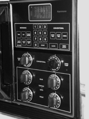
Did you ever wonder what happens when you touch a function on the touch panel keypad on a microwave, range, washer, or room air conditioner? In this chapter, I will explain the sequence of events from behind the control panel (Figure 11-1) that occurs when you turn on the appliance or room air conditioner for the first time. In addition, I will discuss the service techniques needed to service electronic components in appliances and air conditioners.
FIGURE 11-1 A typical oven control panel with manual and electronic controls.
With the introduction of electronic components in appliances and room air conditioners, there are consumers, first-time repairers, and even some technicians who do not have a clue as to the operation of the sequence of events that takes place after the product is programmed.
On standard appliances and room air conditioners, consumers will turn knobs and press buttons to set the functions, and sometimes they will have to manually turn their appliances on or off. Appliances and room air conditioners with electronic touch panels (see Figure 11-1) can now be programmed to perform a single event or multiple events and to automatically turn on or off.
Electronic Components in General
Much of the information in this chapter covers electronic components in general, rather than specific models, in order to present a broad overview of operation and service techniques. The pictures and illustrations that are used in this chapter are for demonstration purposes to clarify the description of how to service these appliances and room air conditioners. They in no way reflect a particular brand’s reliability.
How Electronic Appliances and Air Conditioners Operate
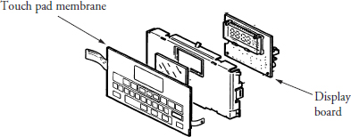
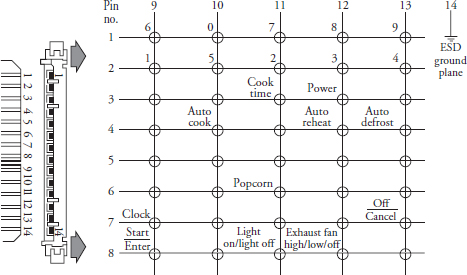
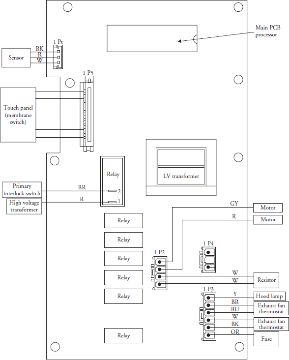
Beginning with the electronic touch panel on the product, the individual will place his or her finger on a function or number to begin the process of programming the product or telling it what action to perform. The electronic touch panel is made up of a thin membrane with a matrix configuration of pressure-sensitive resistive elements that are sealed. When you touch any key pad, you are closing a circuit in the touch panel membrane to be transmitted to the printed circuit board (PCB), called a display board (Figure 11-2). The display board consists of LEDs (light-emitting diodes) or an LCD (liquid crystal display) that shows the consumer what functions have been stored. In Figure 11-3, the schematic illustrates the matrix configuration of the touch panel membrane. A technician can test the individual key pad functions with the electricity off to the product. For example, if you hold down the cook time key pad and place the ohmmeter probes on pins 11 and 13 on the ribbon connector, you should measure a resistance from 50 to 200 ohms. If you measure zero ohms, the touch panel membrane is faulty and must be replaced. Depending on what model you are servicing, the display board may be part of the main processor PCB or it may be a separate PCB entirely. This PCB is powered by a low-voltage transformer that is either mounted on the PCB or mounted somewhere within the appliance. The touch panel and display board are connected to the main processing board (Figure 11-4) by a ribbon cable that is plugged into the main processor board. On some models, all of the components discussed so far may be assembled on to one printed circuit board. After the commands have been entered into the touch panel, the signal is transferred to the main processing PCB to be stored in the main microcomputer chip (CPU) that is mounted on the board (see Figure 11-4). When the user presses the start button, a signal goes to the main CPU chip on the main PCB to initiate the start cycle. The main CPU chip will then select the correct relays to turn on or off the functions that were programmed into it. On some models, the main processor board will send a signal to other PCBs within the appliance to initiate the cycle of events.
FIGURE 11-2 An exploded view of the touch pad membrane, bracket, and the display board.
FIGURE 11-3 A technician can test the matrix configuration of the touch panel membrane at the ribbon connector.
FIGURE 11-4 A pictorial diagram of a main processor printed circuit board.
Electrostatic Discharge
To prevent electrostatic discharge (ESD) from damaging expensive electronic components, simply follow these steps:
• Turn off the electricity to the appliance or air conditioner before servicing any electronic component.
• Before servicing the electronics in an appliance or air conditioner, discharge the static electricity from your body by touching your finger repeatedly to an unpainted surface on the appliance or air conditioner. Another way to discharge the static electricity from your body is to touch your finger repeatedly to the green ground connection on that product.
• The safest way to prevent ESD is to wear an antistatic wrist strap.
• When replacing a defective electronic part with a new one, touch the antistatic package that the part comes in to the unpainted surface of the appliance or air conditioner or to the green ground connection of the appliance or air conditioner.
• Always avoid touching the electronic parts or metal contacts on an integrated board.
• Always handle integrated circuit boards by the edges.
Testing Printed Circuit Boards
Before disassembling or testing can begin, look for the technical data sheets. These are typically attached to the outer cabinet under the appliance, behind the control panel, or behind an access panel. These data sheets will provide you with a lot of helpful information when diagnosing and testing procedures for the appliance or room air conditioner. Most technical data sheets will provide you with a self-diagnostic test sequence that can be programmed through the touch panel. On some models, you can isolate and operate the components through the electronic control to see if they operate. When you initiate the diagnostic test, the main PCB will respond, in most cases, with a code that will indicate where the problem lies. On other models, the fault code appears when a malfunction occurs. In addition, the technical data sheet provides other important information, such as the position of the switch contacts, color-coding of wires, performance data tests, a wiring schematic, and other information that might be helpful to the technician.
The most common problem with electronic components in appliances is loose plug connections and corrosion. Before you begin to replace any component, it is recommended that you disconnect the plug connections from the circuit boards and reconnect them. This process will eliminate any corrosion buildup on the plug connectors or pin connections on the circuit board. In addition, if any plug connections were loose, they will be reattached when you plug them back into the circuit board. Most printed circuit boards have fuses soldered to the circuit board. These fuses must be tested first before condemning the component.
Touch Panel Membrane
Before condemning the touch panel, you need to perform certain inspections. The following is a list of procedures to follow:
• Examine the touch panel membrane (see Figure 11-1) for dents or scratches in the panel. This might cause a short in one or more of the touch pads.
• Inspect the ribbon cable from the touch panel to the display board. Look for evidence of corrosion, tarnishing, or wear on the cable.
• Test all of the keypads and check to see if all functions are working properly.
• If you have to press hard on the touch panel to activate a function, the touch panel will have to be replaced.
• If you press a number and the display shows a different number, the touch panel may have to be replaced.
Transformer
A transformer is an electrical device that can increase (step up) or decrease (step down) the voltage and current. It works on the principle of transferring electrical energy from one circuit to another by electromagnetic induction (Figure 11-5). The primary side of the transformer is the high-voltage side, with the voltage ranging from 120 volts AC to 240 volts AC. On the secondary, or low-voltage, side, the voltage will range from 5 volts AC to 24 volts AC, depending on the amount of voltage and current needed to operate the circuit boards. Some circuit boards require DC voltage to operate, depending on the manufacturer’s requirements for the product.
FIGURE 11-5 A transformer. Most appliances and room air conditioners use a step-down transformer to supply a low voltage to electronic PCBs.
Circuit Board
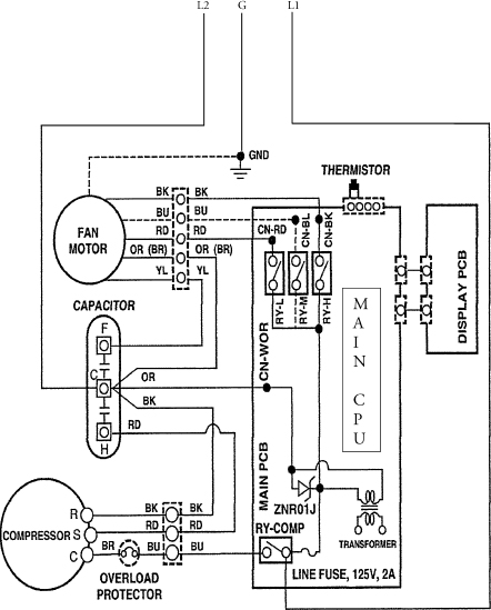
When diagnosing the circuit board, the wiring schematic for the appliance will be helpful in diagnosing, understanding wire color codes, and reading the correct voltages. For example, in Figure 11-6, the main PCB controls the on/off functions and the temperature for the air conditioner. To determine if the main PCB is defective, you would check for the correct supply voltage coming into the PCB. In this case, the voltage should be 120 V AC. In addition, you can also check the voltage at the primary winding of the transformer mounted on the PCB for 120 V AC. Next, test the secondary side of the transformer for output voltage. There is a line fuse on this printed circuit board. Turn off the electricity and check the fuse for continuity. If all checks out, test the relays on the PCB for voltage to the relay coils, or test if the switch contacts on the relays are opening and closing.
FIGURE 11-6 A sample RAC wiring schematic.
A good rule to remember when testing any printed circuit board is that there must be voltage supplied to the board and there must be voltage leaving the board to turn a function on.
Integrated Circuit Chip
An integrated circuit (IC), shown in Figure 7-24, is a miniature electric circuit consisting of transistors, diodes, resistors, capacitors, and all the connecting wiring—all of it manufactured on a single semiconductor chip.
Resistors
A resistor (Figure 7-16a), when installed into an electrical circuit, will add resistance, which will produce a specific voltage drop, or a reduction in current. Resistors can be either fixed or variable.
Sensors
A sensor (examples in Figure 12-17 and Figure 14-55a) is a device that produces a measurable response to a change in a physical condition, such as temperature or humidity, and converts it into a signal that can be read by the microcomputer chip on the printed circuit board.
Sensors are used to measure basic physical phenomena, including:
• Acceleration
• Angular/linear position
• Chemical/gas concentration
• Humidity
• Flow rate
• Force
• Magnetic fields
• Pressure
• Proximity
• Temperature
• Velocity
Temperature Detectors
Thermocouples, thermistors, and resistance temperature detectors (RTDs) are devices that sense and measure temperature. Thermocouples are useful in applications where a wide temperature operating range is anticipated. Thermistors are recommended for applications with a specified temperature range in mind. RTDs are recommended for applications where accuracy and repeatability are important.
Thermistor
A thermistor is a thermally sensitive resistor that exhibits a change in electrical resistance with a change in its temperature. They are a semiconductor composed of metallic oxides such as manganese, nickel, cobalt, copper, iron, and titanium. Thermistors can be various shapes. There are two types of thermistors: negative temperature coefficient (NTC) and positive temperature coefficient (PTC), with the most common being NTC.
Thermistors are used in the following products:
• Automatic dryers
• Automatic washers
• Refrigerators
• Ovens
Thermocouple
A thermocouple (Figure 12-16) is a measuring device manufactured by joining two dissimilar metals at one end. A voltage is generated when a temperature gradient exists between the wire junction and a reference junction. This measurable change of electric potential is the basis of the thermocouple method. Thermocouple junctions are manufactured in three forms: exposed, grounded, and ungrounded. The exposed junction was designed for a faster response.
Resistance Temperature Detector
An RTD (Figure 12-15) is a resistance temperature detector. The RTD’s function is similar to the thermistor. It is a device that provides a useable change in resistance to a specified temperature change. Unlike thermocouples, RTDs are not self-powered. A current must be passed through the RTD, the same as with thermistors, and the change of voltage with temperature is measured.
Thermopile
A thermopile is a thermoelectric device that consists of an array of thermocouple junction pairs connected electrically in series. This device does not measure temperature, but generates an output voltage proportional to the temperature difference or temperature gradient where the device is installed.
Transducer
A transducer is a sensing device that converts one type of energy to another and sends information to the microcomputer chip on the electronic control board.
Diode
A diode (Figures 6-24 and 6-25) is an electrical device that allows current to flow in one direction only. There are many types of uses for diodes besides rectification. These include capacitance that varies with the amount of voltage applied to the diode and photoelectric effects.
LED
Light-emitting diodes, or LEDs as they are usually called, generate light when a current is passed through them. LEDs are used in appliances to indicate if a control is on or off.
Bridge Rectifier
The bridge rectifier (Figure 7-21), consists of four diodes connected together in a bridge configuration on the circuit board. On electronic control boards, a bridge rectifier is used to convert alternating current into direct current for low-voltage circuitry.
Triac
A triac (Figure 7-22), is a three-terminal electronic device that is similar to a diode, except that it allows current to flow in both directions, as with alternating current. There is no anode or cathode in the triac, and it acts as a high-voltage switch on an electronic control board that will turn loads on or off in the circuit.
Transistor
A transistor is a three-element, electronic, solid-state component that is used in a circuit to control the flow of current or voltage. It opens or closes a circuit just like a switch (Figure 7-23a).
Inverter Board
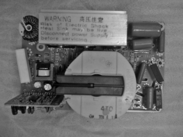
Inverter boards (Figure 11-7) are used on refrigerators, microwaves, and automatic washers. They convert 120-volt, single-phase, 60-Hertz alternating current into three-phase alternating current, either 230-volt alternating current with frequency variations from 57 Hertz to 104 Hertz, or into a specified direct current voltage, single- or three-phase, with varying frequencies.
FIGURE 11-7 A microwave inverter board.
Piezoelectric Ignitor
A piezoelectric ignitor (Figure 11-8) can generate voltages sufficient to spark across an electrode gap, and thus can be used as ignitors in gas water heaters, gas ranges, and gas ovens. Piezoelectric ignition systems are small and simple, and are made from crystalline minerals.
FIGURE 11-8 A piezoelectric ignitor used to light the gas flame in a gas water heater.
