200.2. General. Generally, all grounded conductors used in premises wiring systems must be identified as described in 200.6. As indicated in the first paragraph of this rule, some circuits and systems may be operated without an intentionally grounded conductor—that is, without a grounded neutral or a grounded phase leg. Those situations that are exempted from compliance with this rule are specifically identified here. Some NEC provisions prohibit circuits from being grounded, such as 250.22, 411.5(A), 503.155, 517.61, 668.21(A), and 680.23(A)(2) which all require use of ungrounded circuits. Ungrounded circuits are required in anesthetizing locations where flammable anesthetics are used—which include hospital operating rooms, delivery rooms, emergency rooms, and any place where flammable anesthetics are administered. Although flammable anesthetics are no longer used in the United States, they are used in some other countries that use the NEC, so the provisions are still in the Code. Other exempted sections are permitted to be grounded, but are not required to be grounded.
Grounded conductors must have the same insulation voltage rating as the ungrounded conductors in all circuits rated up to 1000 V—which means in all the commonly used 240/120-, 208/120-, and 480/277-V circuits. To correlate with 250.184 on minimum voltage rating of insulation on grounded neutrals of high-voltage systems, 250.184 and 200.2 state that where an insulated, solidly grounded neutral conductor is used with any circuit rated over 1000 V—such as in 4160/2400- or 13,200/7600-V solidly grounded neutral circuits—the neutral conductor does not have to have insulation rated for either phase-to-phase or phase-to-neutral voltage, but must have insulation rated for at least 600 V. See 250.184. (Of course, a bare, solidly grounded neutral conductor may be used in such circuits that constitute service-entrance conductors, are direct-buried portions of feeders, or are installed overhead, outdoors—as specified in Sec. 250.184. But when an insulated neutral is used, the previously noted rule on 600-V rating applies.) Both 250.184 and 200.2 represent exceptions to 310.2(A) requiring conductors to be insulated.
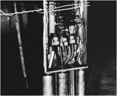
Part (B) of this section is new in the 2008 NEC. The continuity of a grounded circuit conductor must not depend on connections to enclosures, raceways, or cable armor. This problem frequently arises in service panelboards with multiple busbars. Figure 200-1 shows an example of the problem, and how to correct it. The NEC Committee has spent considerable effort in recent years, trying to assure that normal circuit current is confined to recognized conductors, and does not pass over raceways and enclosures that were never designed to be current-carrying conductors.
Fig. 200-1. Violation! The feeder neutral has been terminated on the equipment grounding bus in this service panelboard. The neutral current must flow over the enclosure in order to reach the service neutral, thereby making the continuity of the grounded conductor depend on the enclosure. The feeder neutral must be reterminated on the neutral busbar above.
200.3. Connection to Grounded System. Here the Code prohibits “connection” of a grounded conductor in a premises wiring system to any supply system—the utility feed or generator—that does not also have a grounded conductor. The second sentence clarifies that the “connection” referred to here is a direct connection. Supply of grounded conductor through a transformer is acceptable, even if the supply system does not contain a grounded conductor.
200.6. Means of Identifying Grounded Conductors. The basic rule in part (A) requires that any grounded neutral conductor or other circuit conductor that is operated intentionally grounded must have a white or gray outer finish for the entire length of the conductor, or a conductor with three white stripes encircling other than green insulation is also permitted, or colored threads in white or gray insulation, if the conductor is 6 AWG size or smaller. See Fig. 200-2.
Fig. 200-2. Generally any grounded circuit conductor that is No. 6 size or smaller must have a continuous white or gray outer finish. [Sec. 200.6(A).]
Exempted by parts (A)(1) through (A)(4) from the requirement of 200.6 for a white, gray, or three white striped neutral are mineral-insulated, metal-sheathed cable; single conductors used as the grounded conductor in photovoltaic systems provided the conductor’s insulation is rated for outdoor use and is “sunlight resistant”; fixture wires as covered by 402.8; and neutrals of aerial cable—which may have a raised ridge on the exterior of the neutral to identify them.
The rule of 200.6(B) requires any grounded conductor larger than No. 6 to either comply with the usual identification rules, or to be marked with white or gray identification (such as white tape) encircling the conductor at all terminations at the time of installation. This is the usual approach in the field, since colored insulation is seldom available as a stock item on larger conductors. See Fig. 200-3.
In the rule of part (D), color coding must distinguish between grounded circuit conductors where branch circuits and/or feeders of different systems are in the same raceway or enclosure. This rule ensures that differentiation between grounded circuit conductors of different wiring systems in the same raceway or other enclosure is provided for feeder circuits as well as branch circuits. (See Fig. 200-4.) Because gray is now permitted as a color choice for grounded conductors, identifying two systems in an enclosure is easily done with white wire for one system and gray for the other. You can also use white or gray wire with a stripe, which would become a requirement if there are three or more systems in a common enclosure, although such wires are usually only available on special order and with a very large minimum length.
Fig. 200-3. Conductors of colors other than white or gray—in sizes larger than No. 6—may be used as grounded neutrals or grounded phase legs if marked white at all terminations—such as by white tape on the grounded feeder neutrals, at left. [Other color tapes are used on other circuit conductors to identify the three phases as A, B, and C—as required by 210.5(C) for branch circuits and 215.12(C) for feeders.] [Sec. 200.6(B).]
For approximately 75 years (since 1923) the NEC described the customary identification rule in terms of “white or natural gray” coloring. This originally referred to the color of latex insulation and the unbleached muslin put over it. It wasn’t exactly either white or gray, but installers knew what it was. It was never intended to be the controlled color gray, and conductors manufactured in this way have not been produced for many decades. In fact, the controlled color gray could always have been used, and occasionally was used as an ungrounded conductor. However, with the advent of 480Y/277-V systems, the controlled color gray was increasingly used as an identified conductor based on an improper interpretation of the old terminology “natural gray.” The 2002 NEC ratified what had become the convention, dropped the term “natural gray” completely, and recognized the controlled color gray as a permitted color for identified conductors for the first time. However, since gray wires were permitted, at least theoretically, for use as ungrounded conductors, the NEC advises caution when working with gray wires on existing systems.
Fig. 200-4. Grounded circuit conductors must have color identification and must be distinguishable by system wherever they enter a cable assembly, common raceway, or other common enclosure. [Sec. 200.6(D).]
The basic rules of 200.6(A) and (B) require the use of continuous white or gray or three continuous white stripes running the entire length of an insulated grounded conductor (such as grounded neutral). But the Code permits the use of a conductor of other colors (black, purple, yellow, etc.) for a grounded conductor in a multiconductor cable under certain conditions (see Fig. 200-5):
1. That such a conductor is used only where qualified persons supervise and do service or maintenance on the cable—such as in industrial and mining applications.
2. That every grounded conductor of color other than white or gray will be effectively and permanently identified at all terminations by distinctive white marking or other effective means applied at the time of installation.
This permission for such use of grounded conductors in multiconductor cable allows the practice in those industrial facilities where multiconductor cables are commonly used—although the rule does not limit the use to industrial occupancies. Be aware that this permission does not apply to conductors in a raceway, regardless of the degree of supervision. In a raceway, it is assumed there is no good reason why a conductor with the wrong color insulation cannot be replaced with one having the appropriate color insulation if its function changes. See also Sec. 200.7 and Fig. 200-6.
Fig. 200-5. [Sec. 200.6(E).]
Fig. 200-6. A white- or gray-colored conductor must normally be used only as a grounded conductor (the grounded circuit neutral or grounded phase leg of a delta system). (Sec. 200.7.)
200.7. Use of White or Gray Color or Three Continuous White Stripes. The previous section covered how to identify grounded conductors, the usual, but not the only approach being white or gray color coding. This section has the reciprocal function of covering how the colors white and gray are to be limited in their allowable uses. It is a subtle difference, but taking these sections together definitively covers white/gray usage in the NEC.
The basic rule here limits conductors with outer covering colored white or gray or with three continuous white stripes on other colors to use only as grounded conductors (i.e., as grounded neutral or grounded phase or line conductors [see Fig. 200-6]). In addition, those conductors reidentified at the time of installation as “grounded” conductors (usually the neutral of a grounded system) must actually be grounded conductors. [200.7(A).]
Figure 200-7 shows a white-colored conductor used for an ungrounded phase conductor of a feeder to a panelboard. As shown in the left side of the panel bottom gutter, the white conductor has black tape wrapped around its end for a length of a few inches. The Code used to permit a white conductor to be used for an ungrounded (a hot phase leg) conductor if the white is “permanently reidentified”—such as by wrapping with black or other color tape—to indicate clearly and effectively that the conductor is ungrounded. However, the permission given for such application of white or gray, or even the three white stripes on conductors of other colors, has been eliminated for other than cable assemblies, multiconductor flexible cord, and for circuits “of less than 50 V.”
Fig. 200-7. Violation! White conductor in lower left of panel gutter is used as an ungrounded phase conductor of a feeder, with black tape wrapped around the conductor end to “reidentify” the conductor as not a grounded conductor. Although such practice was previously permitted, the NEC no longer recognizes it. (Sec. 200.7.)
Part (B) of 200.7 covers the use of conductors whose insulation is white, gray, or has three continuous white stripes for circuits operating at 50 V, or less. Circuit conductors in such systems that have an insulation coloring or configuration reserved for “grounded” conductors are not required to be grounded unless required by 250.20, which identifies those systems that must be operated with a grounded conductor. If the low-voltage system in question is supplied from a transformer whose primary supply voltage is over 150 V to ground; or if the supply transformer’s primary conductors are not grounded; or where the low-voltage system is run overhead outdoors, 250.20(A) would mandate grounding of one of the circuit conductors. And therefore, reidentifying a conductor with an overall outer covering or insulation that is one of the colors or configurations reserved for grounded conductors, as an ungrounded conductor, is prohibited.
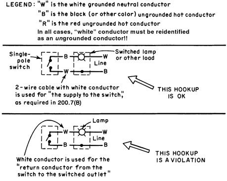
Part (C)(1) indicates conditions under which a white conductor in a cable (such as BX or nonmetallic-sheathed cable) may be used for an ungrounded (hot-leg) conductor. When used as described, the white conductor is acceptable even though it is not a grounded conductor, provided it is reidentified (such as by painting or taping). Figure 200-8 shows examples of correct and incorrect hookups of switch loops where the hot supply is run first to the switched outlet, then to switches, which is covered by Part (C)(2) of 200.7.
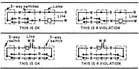
Fig. 200-8. For switch loops from load outlets with hot supply to the load outlet, white conductor in cable must be the “supply to the switch.” Also, the white conductors must be reidentified at the time of installation. [Sec. 200.7(C)(2).]
The former unrestricted allowance to use the white wire in a cable assembly as the supply side of a switch leg, something every apprentice learns in the first year, is still in the Code but now the white wire must be reidentified at terminations and other places where it is “visible and accessible.” The substantiation for this change was the experience of a manifestly unqualified person who got a shock because he was confused by the function of the white wire in a switch loop.
200.7(C)(3) covers flexible cords for connecting any equipment recognized by 400.7 for cord-and-plug connection to a receptacle outlet.
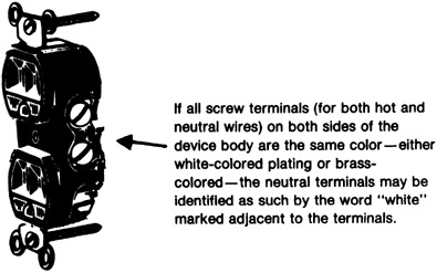
200.10. Identification of Terminals. Part (B) permits a grounded terminal on a receptacle to be identified by the word “white” or the letter “W” marked on the receptacle as an alternative to the use of terminal parts (screw, etc.) that are “substantially white in color.”
Marking of the word “white” or the letter “W” provides the required identification of the neutral terminal on receptacles that require white-colored plating on all terminals of a receptacle for purposes of corrosion resistance or for connection of aluminum conductors. Obviously, if all terminals are white-colored, color no longer serves to identify or distinguish the neutral as it does if the hot-conductor terminals are brass-colored. And as the rule is worded, the marking “white” or the letter “W” may be used to identify the neutral terminal on receptacles that have all brass-colored terminal screws. See Fig. 200-9.
Fig. 200-9.
Subpart (2) of part (B) permits a push-in-type wire terminal to be identified as the neutral (grounded) conductor terminal either by marking the word “white” or the letter “W” on the receptacle body adjacent to the conductor entrance hole or by coloring the entrance hole white—as with a white-painted ring around the edge of the hole.
The rule of part (C) is shown in Fig. 200-10.
Part (E) of Sec. 200.10 requires that the grounded conductor terminal of appliances be identified—to provide proper connection of field-installed wiring (either fixed wiring connection or attachment of a cord set).
The rule applies to “appliances that have a single-pole switch or a single-pole overcurrent device in the line or any line-connected screw-shell lampholder” and requires simply that some “means” (instead of “marking”) be provided to identify the neutral. As a result, use of white color instead of marking is clearly recognized for such neutral terminals of appliances.
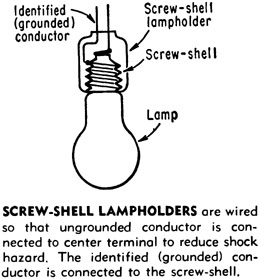
Fig. 200-10. Screw-shell sockets must have the grounded wire (the neutral) connected to the screw-shell part. [Sec. 200.10(C).]
200.11. Polarity of Connections. This rule makes failure to observe the proper polarity when terminating conductors a Code violation. Installers are required to ensure that each and every grounded conductor is connected to the termination specifically identified as the neutral point of connection. Any connection either of grounded conductors to “other” termination points, or the connection of an ungrounded conductor to an identified “grounded” conductor connection point, is clearly and specifically prohibited.
210.1. Scope. Article 210 covers all branch circuits other than those “specific-purpose branch circuits” such as those that supply only motor loads, which are covered in Art. 430. This section makes clear that the article covers branch circuits supplying lighting and/or appliance loads as well as branch circuits supplying any combination of those loads plus motor loads or motor-operated appliances, unless the branch circuit is one identified in Table 210. 2, “Specific-Purpose Branch Circuits.” Where motors or motor-operated appliances are connected to branch circuits supplying lighting and/or appliance loads, the rules of both Arts. 210 and 430 apply. Article 430 alone applies to branch circuits that supply only motor loads.
210.2. Other Articles for Specific-Purpose Branch Circuits. This rule provides correlation with specific branch-circuiting requirements in other articles. There are a number of “specific-purpose” circuits identified in this rule that must be laid-out and installed in compliance with the specific requirements of those rules shown. However, all the rules of Art. 210 continue to apply, except to the extent modified by the other provisions.
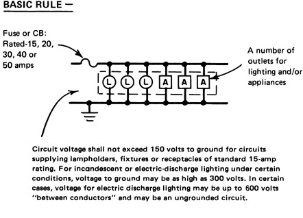
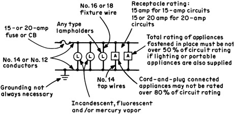
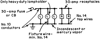
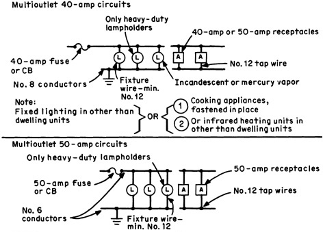
210.3. Rating. A branch circuit is rated according to the rating of the overcurrent device used to protect the circuit. A branch circuit with more than one outlet must normally be rated at 15, 20, 30, 40, or 50 A (see Fig. 210-1). That is, the protective device must generally have one of those ratings for multioutlet circuits, and the conductors must meet the other size requirements of Art. 210.
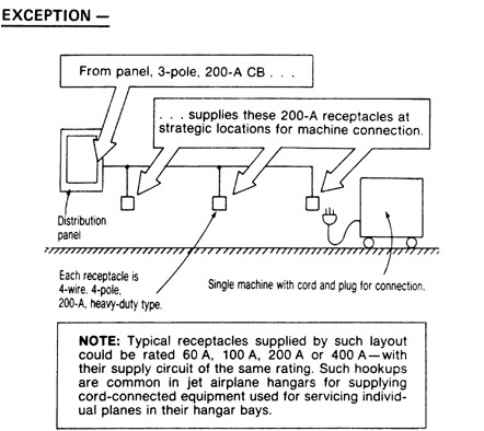
Fig. 210-1. A multioutlet branch circuit must usually have a rating (of its overcurrent protective device) at one of the five values set by 210.3. (Sec. 210.3.)
Under the definition for “receptacle” in NE Code Art. 100, it clearly provides that a duplex receptacle is two receptacles and not one—even though there is only one box and therefore one outlet. However, a circuit that supplies only one duplex receptacle is still usually not an “individual branch circuit” because it normally will be likely to supply more than one utilization equipment through its separate receptacles, and therefore flunk the definition of “individual branch circuit” in Art. 100. If an individual branch circuit is required for any reason, and the purpose is to supply cord-and-plug connected utilization equipment, a single receptacle must be installed. One example is the individual branch-circuit required in 422.16(B)(4)(5) for a cord-and-plug connected range hood.
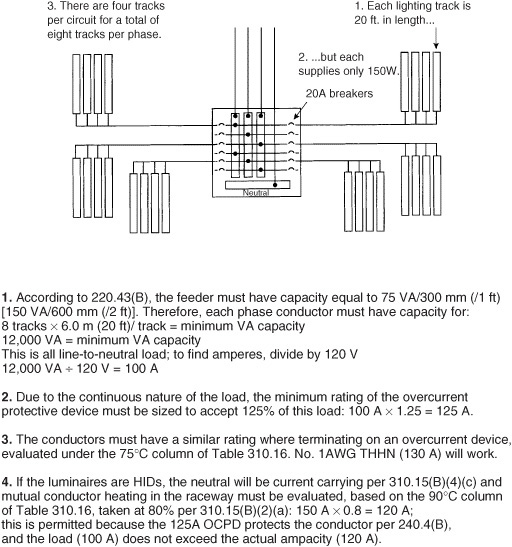
The Exception to the rule of 210.3 gives limited permission to use multioutlet branch circuits rated over 50 A—but only to supply nonlighting loads and only in industrial places where maintenance and supervision ensure that only qualified persons will service the installation. This Exception recognizes a real need in industrial plants where a machine or other electrically operated equipment is going to be provided with its own dedicated branch circuit of adequate capacity—in effect, an individual branch circuit—but where such machine or equipment is required to be moved around and used at more than one location, requiring multiple points of outlet from the individual branch circuit to provide for connection of the machine or equipment at any one of its intended locations (see Fig. 210-2). For instance, there could be a 200-A branch circuit to a special receptacle outlet or a 300-A branch circuit to a single machine. In fact, the wording used here actually recognizes the use of such a circuit to supply more than one machine at a time, but other realities of application make such an approach impractical.
Fig. 210-2. A circuit to a single load device or equipment may have any rating. (Sec. 210.3.)
It is important to note that it is the size of the overcurrent device that actually determines the rating of any circuit covered by Art. 210, even when the conductors used for the branch circuit have an ampere rating higher than that of the protective device. In a typical case, for example, a 20-A circuit breaker in a panelboard might be used to protect a branch circuit in which 10 AWG conductors are used as the circuit wires. Although the load on the circuit does not exceed 20 A, and 12 AWG conductors would have sufficient current-carrying capacity to be used in the circuit, the 10 AWG conductors with their rating of 30 A were selected to reduce the voltage drop in a long homerun. The rating of the circuit is 20 A because that is the size of the overcurrent device. The current rating of the wire does not enter into the ampere classification of the circuit.
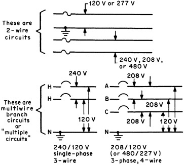
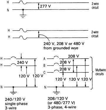
210.4. Multiwire Branch Circuits. A “branch circuit,” as covered by Art. 210, may be a 2-wire circuit or may be a “multiwire” branch circuit. A “multiwire” branch circuit consists of two or more ungrounded conductors having a potential difference between them and an identified grounded conductor having equal potential difference between it and each of the ungrounded conductors and which is connected to the neutral conductor of the system. Thus, a 3-wire circuit consisting of two opposite-polarity ungrounded conductors and a neutral derived from a 3-wire, single-phase system or a 4-wire circuit consisting of three different phase conductors and a neutral of a 3-phase, 4-wire system is a single multiwire branch circuit. This is only one circuit, even though it involves two or three single-pole protective devices in the panelboard (Fig. 210-3). This is important, because other sections of the Code refer to conditions involving “one branch circuit” or “the single branch circuit.” (See 250.32 Exception and 410.65.)
Fig. 210-3. Branch circuits may be 2-wire or multiwire type. (Sec. 210.4.)
The wording of part (A) of this section makes clear that a multiwire branch circuit may be considered to be either “a single circuit” or “multiple circuits.” This coordinates with other Code rules that refer to multiwire circuits as well as rules that call for two or more circuits. For instance, 210.11(C)(1) requires that at least two 20-A small appliance branch circuits be provided for receptacle outlets in those areas specified in 210.52(B)—that is, the kitchen, dining room, pantry, and breakfast room of a dwelling unit. The wording of this rule recognizes that a single 3-wire, single-phase 240/120-V circuit run to the receptacles in those rooms is equivalent to two 120-V circuits and satisfies the rule of 210.11(C)(1).
In addition, a “multiwire” branch circuit is considered to be a single circuit of multiple-wire makeup. That will satisfy the rule in 410.65, which recognizes that a multiwire circuit is a single circuit when run through end-to-end connected lighting fixtures that are used as a raceway for the circuit conductors. Only one principal circuit—either a 2-wire circuit or a multiwire (3- or 4-wire) circuit—may be run through fixtures connected in a line.
The FPN following part (A) of 210.4 warns of the potential for “neutral overload” where line-to-neutral nonlinear loads are supplied. This results from the additive harmonics that will be carried by the neutral in multiwire branch circuits. In some cases, where the load to be supplied consists of, or is expected to consist of, so-called nonlinear loads that are connected line-to-neutral, it may be necessary to use an oversized neutral (up to two sizes larger), or each phase conductor could be run with an individual full-size neutral. Either way, a derating of 80 percent would be required for the number of conductors [see 310.15(B)(4)(c)].
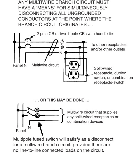
Part (B) of this section requires a “means” to simultaneously disconnect all ungrounded conductors of a multiwire branch circuit “at the point where the branch circuit originates.” Although at one time this was a dwelling unit provision for split-wired receptacles, and then it applied in all occupancies to multiple devices on one yoke, it now applies to all multiwire circuits serving any loads in all occupancies. There is a long and unfortunate history of unqualified persons creating havoc when working on multiwire circuits without protecting against the consequences of open neutrals and of voltage backfeeding into an outlet from a different leg than the one thought to be at issue. Now a common disconnecting means will be in an obvious and prominent location when the branch circuit is being disconnected.
A multipole circuit breaker (CB) certainly complies with this rule, as would a multipole fused switch. Single-pole circuit breakers connected together with approved handle ties presumably qualify, although this is not perfectly clear from the Code text. Remember that handle ties are for operation by hand; they are not rated to automatically open the companion breaker if only one leg trips. Even less clear is a multipole switch located immediately adjacent to the panel where the circuit originates. This would be the only practical option on an existing fusible panelboard.
The objective is to assure that when someone goes to deenergize an ungrounded conductor of some equipment being maintained or replaced, that person will open all the conductors and thereby preclude line voltage from appearing on the load-side neutral conductor through loads connected on another leg of the circuit. In other words, this rule serves a maintenance function. If the purpose were electrical, even fuses in a multipole fused switch, would have been disallowed because they are inherently single-pole devices and if one opens, the others still provide power to the other legs. In this regard, note that the wording here differs from the requirement in 210.4(C) Exception No. 2, which serves an electrical function and clearly does require a multipole circuit breaker for other reasons. On this basis a good case can be made for the multipole switch adjacent to the panel, but this is certainly subject to local interpretation.
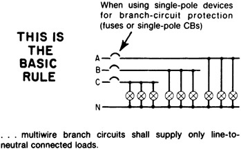
The basic rule of part (C) addresses the need for personnel safety. To help minimize the possibility of shock or electrocution during maintenance or repair, this section states that multiwire branch circuits (such as 240/120-V, 3-wire, single-phase and 3-phase, 4-wire circuits at 208/120 or 480/277 V) may be used only with loads connected from a hot or phase leg to the neutral conductor (Fig. 210-4). However, while generally prohibited, where additional measures are taken to protect personnel, the two exceptions to this rule permit supplying “other than line-to-neutral loads” from multiwire branch circuits. The two exceptions to that rule are shown in Fig. 210-5.
Fig. 210-4. With single-pole protection only line-to-neutral loads may be fed. (Sec. 210.4.)
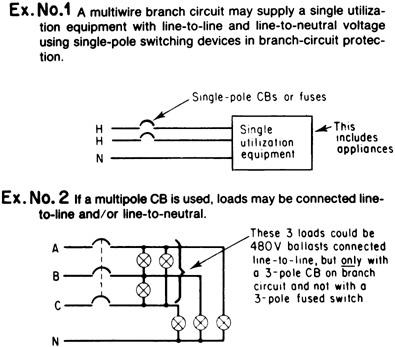
Fig. 210-5. Line-to-line loads may only be connected on multiwire circuits that conform to the Exceptions given. (Sec. 210.4.)
Exception No. 1 permits use of single-pole protective devices for an individual circuit to “only one utilization equipment”—in which the load may be connected line-to-line as well as line-to-neutral. “Utilization equipment,” as defined in Art. 100, is “equipment which utilizes electric energy for electronic, electromechanical, chemical, heating, lighting, or similar purposes.” The definition of “appliance,” in Art. 100, notes that an appliance is “utilization equipment, generally other than industrial, that is normally built in standardized sizes or types and is installed or connected as a unit to perform one or more functions such as washing clothes, air conditioning, food mixing, deep frying, and so forth.” Because of those definitions, the wording of Exception No. 1 opens its application to commercial and industrial equipment as well as residential. It should be noted that 210.4(B) applies in these cases, and therefore means must still be provided, such as handle ties, to provide for simultaneous opening of a set of single-pole breakers installed for this equipment.
Exception No. 2 permits a multiwire branch-circuit to supply line-to-line connected loads, but only when it is protected by a multipole circuit breaker (CB). The intent of Exception No. 2 is that line-to-line connected loads may be used (other than in Exception No. 1) only where the poles of the circuit protective device operate together, or simultaneously. A multipole CB satisfies the rule, but a fused multipole switch would not comply because the hot circuit conductors are not “opened simultaneously by the branch-circuit overcurrent device.” This rule requiring a multipole CB for any circuit that supplies line-to-line connected loads as well as line-to-neutral loads was put in the Code to prevent equipment loss under the conditions shown in Fig. 210-6. Use of a 2-pole CB in the sketch would cause opening of both hot legs on any fault and prevent the condition shown.
Fig. 210-6. Single-pole protection can expose equipment to damage. (Sec. 210.4.)
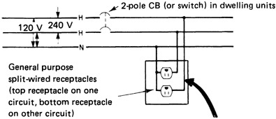
Figure 210-7 shows that a 2-pole CB, two single-pole CBs with a handle tie that enables them to be used as a 2-pole disconnect, or a 2-pole switch ahead of branch-circuit fuse protection will satisfy the requirement that both hot legs must be interrupted when the disconnect means is opened to deenergize a multiwire circuit to a split-wired receptacle. This Code rule provides the greater safety of disconnecting both hot conductors simultaneously to prevent shock hazard in replacing or maintaining any piece of electrical equipment where only one of two hot supply conductors has been opened.
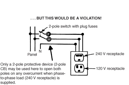
Fig. 210-7.
It should also be noted that although a 2-pole switch ahead of fuses may satisfy as the simultaneous disconnect required ahead of split-wired receptacles, such a switch does not satisfy as the simultaneous multipole “branch-circuit protective device” that is required by Exception No. 2 of 210.4 when a multi-wire circuit supplies any loads connected phase-to-phase. In such a case, a 2-pole CB must be used because fuses are single-pole devices and do not ensure simultaneous opening of all hot legs on overcurrent or ground fault.
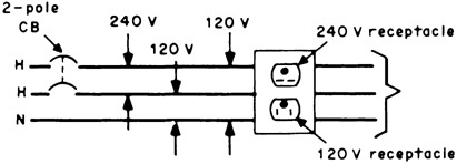
It should be noted that the threat of motor burnout, shown in the diagram of Fig. 210-6, may exist just as readily where the 230-V resistance device and the 115-V motor are fed from a dual-voltage (240-V, 120-V) duplex receptacle as where loads are fixed wired. As shown in Fig. 210-8, the rule of 210.4 does clearly call for a 2-pole CB (and not single-pole CBs or fuses) for a circuit supplying a dual-voltage receptacle. In such a case, a line-to-line load and a line-to-neutral load could be connected and subjected to the condition shown in Fig. 210-6.
Fig. 210-8. A dual-voltage receptacle requires a 2-pole CB on its circuit. (Sec. 210.4.)
At the end of part (C), a fine-print note calls attention to 300.13(B), which requires maintaining the continuity of the grounded neutral wire in a multiwire branch circuit by pigtailing the neutral to the neutral terminal of a receptacle. Exception No. 2 of 210.4(C) and 300.13(B) are both aimed at the same safety objective—to prevent damage to electrical equipment that can result when two loads of unequal impedances are series-connected from hot leg to hot leg as a result of opening the neutral of an energized multiwire branch circuit or are series-connected from hot leg to neutral. 300.13(B) prohibits dependency upon device terminals (such as internally connected screw terminals of duplex receptacles) for the splicing of neutral conductors in multiwire (3- or 4-wire) circuits. Grounded neutral wires must not depend on device connection (such as the break-off tab between duplex-receptacle screw terminals) for continuity. White wires can be spliced together, with a pigtail to the neutral terminal on the receptacle. If the receptacle is removed, the neutral will not be opened.
This rule is intended to prevent the establishment of unbalanced voltages should a neutral conductor be opened first when a receptacle or similar device is replaced on energized circuits. In such cases, the line-to-neutral connections downstream from this point (farther from the point of supply) could result in a considerably higher-than-normal voltage on one part of a multiwire circuit and damage equipment, because of the “open” neutral, if the downstream line-to-neutral loads are appreciably unbalanced. Refer to the description given in 300.13 of this book.
Part (D) of this section, new in the 2008 NEC, requires that all conductors of a multiwire branch circuit, including the associated neutral conductor, be grouped in the panelboard or other point of circuit origination. If the conductors enter in a cable assembly that makes the grouping obvious, or in a raceway containing only to one multiwire circuit so that the grouping is obvious, then the rule is satisfied. However, if multiple multiwire circuits enter through a common raceway, then you must keep track of which white (or gray) wire goes with which ungrounded conductors, and group those wires together at least once using wire ties or similar methods. Note that if two cable assembles enclosing multiwire circuits enter a panel through a duplex cable connector, additional grouping within the panel would probably be required because the cable grouping would no longer qualify as “obvious.”
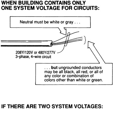
210.5. Identification for Branch Circuits. For grounding and grounded conductors this section simply directs the reader to comply with other Code rules that cover conductor color-coding or color-identification schemes. It directs that “grounded” and “grounding” conductors in branch circuits utilize the specific color identification given in 200.6 and 250.119. Those rules generally reserve the color green for equipment grounding conductors and white, gray, or three continuous white stripes on other than green-colored insulation for the grounded conductors in branch circuits.
It should be noted that rules on color coding of conductors given in Art. 210 apply only to branch-circuit conductors and do not directly require color coding of feeder conductors. But the rules given in 200.6 and 250.119 must generally be observed, and would apply to feeder and service conductors. 215.12 also requires identification of phase legs of feeders to panelboards, switchboards, and so forth—and that requires some technique for marking the phase legs; those provisions are now harmonized with the ones here for branch circuits. Note that many design engineers have insisted on color coding of feeder conductors all along to afford effective balancing of loads on the different phase legs.
Color identification for branch-circuit conductors is divided into three categories:
Grounded conductor As indicated, grounded conductors must satisfy 200.6. That rule generally requires that the grounded conductor of a branch circuit (the neutral of a wye system or a grounded phase of a delta) must be identified by a continuous white or gray color for the entire length of the conductor, or have three continuous white stripes for its entire length on other than green insulation. Where wires of different systems (such as 208/120 and 480/277) are installed in the same raceway, box, or other enclosure, the neutral or grounded wire of one system must be white or gray or have the three continuous white stripes on other than green insulation; and the neutral of the other system must be white with a color stripe, or be gray if the first one is white, etc., or it must be otherwise distinguished—such as by painting or taping. The point is that neutrals of different systems must be distinguished from each other when they are in the same enclosure [200.6(D) and Fig. 210-9]. For more, See 200.6.

Fig. 210-9. Separate identification of ungrounded conductors is required only if a building utilizes more than one nominal voltage system. Neutrals must be color-distinguished if circuits of two voltage systems are used in the same raceway, but not if different voltage systems are run in separate raceways. [Sec. 210.5(C).]
Hot conductor The NE Code requires that individual hot conductors be identified where a building has more than one nominal voltage system. In contrast to the rule for grounded circuit conductors, the coding rules for these wires apply anytime multiple voltage systems exist in a building, whether or not they happen to share an enclosure. Another difference is that the grounded conductor identification scheme applies over the entire length of the conductor for 6 AWG and smaller conductors, but the ungrounded conductors need only be identified at “termination, connection, and splice points.”
Grounding conductor An equipment grounding conductor of a branch circuit (if one is used) must be color-coded green or green with one or more yellow stripes—or the conductor may be bare [250.119].
In part (C), an important rule for branch circuits requires some means of identification of hot (ungrounded) conductors of branch circuits in a building that contains wiring systems operating at two or more different voltage levels. That means that one needs to identify all branch circuits including individual branch circuits, as well as single-phase and three-phase power circuits whether or not a neutral is part of the branch circuit. However, every branch-circuit panelboard—in both the 208Y/120-V system and the 408Y/277-V system—must have the means of identification marked on it—but in a key clarification for 2008, the panel identification label need only specify the system in use for circuits originating within it. It is not necessary to create complicated, fully reciprocal labels that describe every color code for every voltage system in the building. Such identification is also required in 215.12 for feeders, including the marking of feeder panels.
This Code rule and that given in 215.12 restore the need to identify phase legs of branch and feeder circuits where more than one voltage system is used in a building. For instance, a building that utilizes both 208Y/120-V circuits and 480Y/277-V circuits must have separate and distinct color coding of the hot legs of the two voltage systems—or must have some means other than color coding such as tagging, marking tape (color or numbers), or some other identification that will satisfy the inspecting agency. And this new rule further states that the “means of identification must be permanently posted at each branch-circuit panelboard or similar branch-circuit distribution equipment”—to tell how the individual phases in each of the different voltage systems are identified (Fig. 210-9).
The wording of the new rule requires that the “means of identification” must distinguish between all conductors “by system.” But, if a building uses only one voltage system—such as 208Y/120 V or 240/120 V single phase, no identification is required for the circuit phase (the “hot” or ungrounded) legs. And where a building utilizes two or more voltage systems, the separate, individual identification of ungrounded conductors must be done whether the circuits of the different voltages are run in the same or separate raceways.
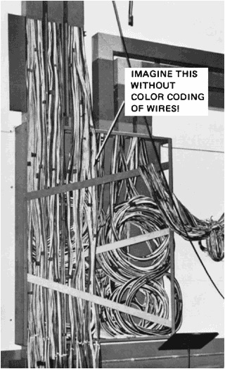
Color coding of circuit conductors (or some other method of identifying them), as required by 210.5(C), is a wiring consideration that deserves the close, careful, complete attention of all electrical people. Of all the means available to provide for the ready identification of the two- or three-phase legs and neutrals in wiring systems, color coding is the easiest and surest way of balancing loads among the phase legs, thereby providing full, safe, effective use of total circuit capacities. In circuits where color coding is not used, loads or phases get unbalanced, many conductors are either badly underloaded or excessively loaded, and breakers or fuses sometimes are increased in size to eliminate tripping due to overload on only one-phase leg. Modern electrical usage—for reasons of safety and energy conservation, as well as full, economic application of system equipment and materials—demands the many real benefits that color coding can provide.
For the greater period of its existence, the NE Code required a very clear, rigid color coding of branch circuits for good and obvious safety reasons. Color coding of hot legs to provide load balancing is a safety matter. 210.11(B) requires balancing of loads from branch-circuit hot legs to neutral. The rule of 220.61 bases sizing of feeder neutrals on clear knowledge of load balance in order to determine “maximum unbalance.” And mandatory differentiation of voltage levels is in the safety interests of electricians and others maintaining or working on electrical circuits, to warn of different levels of hazard.
Because the vast majority of electrical systems involve no more than two voltage configurations for circuits up to 600 V, and because there has been great standardization in circuit voltage levels, there should be industry-wide standardization on circuit conductor identifications. A clear, simple set of rules could cover the preponderant majority of installations, with exceptions made for the relatively small number of cases where unusual conditions exist and the local inspector may authorize other techniques. Color coding should follow some basic pattern—such as the following:
 120-V, 2-wire circuit: grounded neutral—white; ungrounded leg—black
240/120-V, 3-wire, single-phase circuit: grounded neutral—white; one hot leg—black; the other hot leg—red
208Y/120-V, 3-phase, 4-wire: grounded neutral—white; one hot leg—black; one hot leg—red; one hot leg—blue
240-V, delta, 3-phase, 3-wire: one hot leg—black; one hot leg—red; one hot leg—blue
240/120-V, 3-phase, 4-wire, high-leg delta: grounded neutral—white; high leg (208-V to neutral)—orange; one hot leg—black; one hot leg—blue
480Y/277-V, 3-phase, 4-wire: grounded neutral—gray, one hot leg—brown; one hot leg—orange; one hot leg—yellow
480-V, delta, 3-phase, 3-wire: one hot leg—brown; one hot leg—orange; one hot leg—yellow
By making color coding a set of simple, specific color designations, standardization will ensure all the safety and operating advantages of color coding to all electrical systems. Particularly today, with all electrical systems being subjected to an unprecedented amount of alterations and additions because of continuing development and expansion in electrical usage, conductor identification is a regular safety need over the entire life of the system. (Fig. 210-10.)
Of course, there are alternatives to “color” identification throughout the length of conductors. Color differentiation is almost worthless for color-blind electricians. And it can be argued that color identification of conductors poses problems because electrical work is commonly done in darkened areas where color perception is reduced even for those with good eyesight. The NE Code already recognizes white tape or paint over the conductor insulation end at terminals to identify neutrals (200.6). Number markings spaced along the length of a conductor on the insulation (1, 2, 3, etc.)—particularly, say, white numerals on black insulation—might prove very effective for identifying and differentiating conductors. Or the letters “A,” “B,” and “C” could be used to designate specific phases. Or a combination of color and markings could be used. But some kind of conductor identification is essential to safe, effective hookup of the ever-expanding array of conductors used throughout buildings and systems today. And the method used for identifying ungrounded circuit conductors must be posted at each branch-circuit panelboard to comply with requirements of 210.5(C). Although not required by 210.5(A), the method used to distinguish the grounded (neutral) conductors for the different systems should also be included with that information required for the ungrounded (phase) conductors.
Fig. 210-10. Although only required for branch circuits in buildings with more than one nominal voltage, color identification of branch-circuit phase legs is needed for safe and effective work on grouped circuits. [Sec. 210.5(C).]
The 2008 NEC addresses this by recognizing that some occupancies with very sophisticated operations maintain the circuit identification protocols in documentation at central points. If such documentation is “readily available,” Sec. 210.5(C) allows such on-site records or manuals to substitute for panel-board markings. This degree of sophistication becomes important when, for example, multiple branch circuits running at the same voltage but derived from differing separately derived systems happen to arrive in a common enclosure for some reason. In such cases it may be very useful to know which wire is which, and the simple use of color would probably not be adequate for this purpose.
210.6. Branch-Circuit Voltage Limitations. Voltage limitations for branch circuits are presented here in 210.6. In general, branch circuits serving lampholders, fixtures, cord-and-plug-connected loads up to 12 A, or motor loads rated ¼ hp or less are limited to operation at a maximum voltage rating of 120 V. It should be noted that these rules, for the most part, are aimed at the manufacturers. But designers and installers should be aware of these limitations so that they do not unwittingly apply a given piece of equipment in an other than acceptable manner.
Part (A), Occupancy Limitation, applies specifically to dwelling units—one-family houses, apartment units in multifamily dwellings, and condominium and co-op units—and to guest rooms and suites in hotels and motels and similar residential occupancies, including college dormitories. In such occupancies, any luminaire or any receptacle for plug-connected loads rated up to 1440 VA or for motor loads of less than ¼ hp must be supplied at not over 120 V between conductors.
Note: The 120-V supply to these types of loads may be derived from (1) a 120-V, 2-wire branch circuit; (2) a 240/120-V, 3-wire branch circuit; or (3) a 208/120-V, 3-phase, 4-wire branch circuit. Appliances rated more than 1440 VA, (i.e., ranges, dryers, water heaters, etc.) may be supplied by 240/120-V or 208/120-V circuits in accordance with 210.6(C)(6).
Caution: The concept of maximum voltage not over “120 V . . . between conductors,” as stated in 210.6(A), has caused considerable discussion and controversy in the past when applied to split-wired receptacles and duplex receptacles of two voltage levels. It can be argued that split-wired general-purpose duplex receptacles are not acceptable in dwelling units and in hotel and motel guest rooms because they are supplied by conductors with more than 120 V between them—that is, 240 V on the 3-wire, single-phase, 120/240-V circuit so commonly used in residences. The two hot legs connect to the brass-colored terminals on the receptacle, with the shorting tab broken off, and the voltage between those conductors does exceed 120 V. The same condition applies when a 120/240-V duplex receptacle is used—the 240-V receptacle is fed by conductors with more than 120 V between them.
That interpretation is not supported by the definition of a receptacle, by which a duplex receptacle is actually two receptacles on a single yoke, and each of those receptacles is considered as a separate device. In addition, the rule limits loads over 1440 VA, not devices, and until the load is plugged in, there is no issue. This rule is primarily of interest to manufacturers, who are obliged not to manufacture appliances in violation of these limits. All of that said, there is a legitimate concern with respect to the voltage on the strap when maintenance is being performed, but the current requirements for a common disconnecting means in 210.4(B) and 210.7(B) fully addresses those issues. See Fig. 210-11.
Fig. 210-11. Split-wired receptacles are permitted in residential occupancies (“dwelling units”) and in all other types of occupancies (commercial, institutional, industrial, etc.).
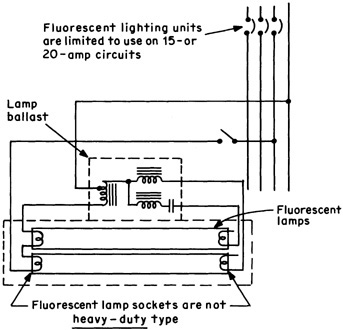
Part (B) begins a sequence of four voltage classifications that apply to all occupancies and that are limiting by reason of voltage alone. This part permits a circuit with not over 120 V between conductors to supply medium-base screw-shell lampholders, ballasts for fluorescent or HID lighting fixtures, and plug-connected or hard-wired appliances—in any type of building or on any premises (Fig. 210-12).
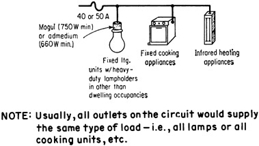
Part (C) applies to circuits with over 120 V between conductors (208, 240, 277, or 480 V) but not over 277 V (nominal) to ground. This is shown in Fig. 210-13, where all of the circuits are “circuits exceeding 120 V, nominal, between conductors and not exceeding 277 V, nominal, to ground.” Circuits of any of those voltages are permitted to supply incandescent lighting fixtures with mogul-base screw-shell lampholders, ballasts for electric-discharge lighting fixtures or plug-connected or hard-wired appliances, or other utilization equipment.
It is important to note that this section no longer contains the requirement for a minimum 8-ft (2.5-m) mounting height for incandescent or electric-discharge fixtures with mogul-base screw-shell lampholders used on 480/277-V systems. However, this still has to be correlated with 225.7(C), which requires that luminaires connected to circuits over 120 V to ground up to 277 V not be located within 3 ft of “windows, platforms, fire escapes, and the like.” So, you can walk up and hug a 277-V bollard-style luminaire on the edge of a sidewalk, but a comparable luminaire on the side of a building must be out of reach.
A UL-listed electric-discharge luminaire rated at 277 V nominal may be equipped with a medium-base screw-shell lampholder and does not require a mogul-base screw-shell. The use of the medium-base lampholder, however, is limited to “listed electric-discharge fixtures.” For 277-V incandescent fixtures, 210.6(C)(3) continues the requirement that such fixtures be equipped with “mogul-based screw-shell lampholders.”
Fig. 210-12. In any occupancy, 120-V circuits may supply these loads. [Sec. 210.6(B).]
Fluorescent, mercury-vapor, metal-halide, high-pressure sodium, low-pressure sodium, and/or incandescent fixtures may be supplied by 480/277-V, grounded-wye circuits—with loads connected phase-to-neutral and/or phase-to-phase. Such circuits operate at 277 V to ground even, say, when 480-V ballasts are connected phase-to-phase on such circuits. Or lighting could be supplied by 240-V delta systems—either ungrounded or with one of the phase legs grounded, because such systems operate at not more than 277 V to ground.
On a neutral-grounded 480/277-V system, incandescent, fluorescent, mercury-vapor, metal-halide, high-pressure sodium, and low-pressure sodium equipment can be connected from phase-to-neutral on the 277-V circuits. If fluorescent or mercury-vapor fixtures are to be connected phase-to-phase, some Code authorities contend that autotransformer-type ballasts cannot be used when these ballasts raise the voltage to more than 300 V, because, they contend, the NE Code calls for connection to a circuit made up of a grounded wire and a hot wire. (See 410.138.) On phase-to-phase connection these ballasts would require use of 2-winding, electrically isolating ballast transformers according to this interpretation. However, the actual wording in 410.138 states the restriction in terms not of whether the supply conductors are grounded, but rather that the supply system be a grounded one, and a 480-V luminaire connected to a 480Y/277-V system is connected to a grounded system.
Fig. 210-13. These circuits may supply incandescent lighting with mogul-base screw-shell lampholders for over 120 V between conductors, electric-discharge ballasts, and cord-connected or permanently wired appliances or utilization equipment. [Sec. 210.6(C).]
210.6(C)(6) clearly permits either “cord-and-plug-connected or permanently connected utilization equipment” to be supplied by a circuit with voltage between conductors in excess of 120 V, and permission is intended for the use of 277-V heaters in dwelling units, as used in high-rise apartment buildings and similar large buildings that may be served at 480/277 V. This is OK in such locations as long as such equipment, if cord-and-plug-connected, is larger than the 1440 VA threshold set in the occupancy limitation in 210.6(A).
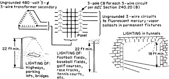
In 210.6(D), the NE Code permits fluorescent and/or high-intensity discharge units to be installed on circuits rated over 277 V (nominal) to ground and up to 600 V between conductors—but only where the lamps are mounted in permanently installed luminaires on poles or similar structures for the illumination of areas such as highways, bridges, athletic fields, parking lots, at a height not less than 22 ft, or on other structures such as tunnels at a height not less than 18 ft (5.5 m). (See Fig. 210-14.) Part (D) covers use of lighting fixtures on 480-V ungrounded circuits—such as fed from a 480-V delta-connected or wye-connected ungrounded transformer secondary.
Fig. 210-14. Ungrounded circuits, at up to 600 V between conductors, may supply lighting only as shown. [Sec. 210.6(D).]
This permission for use of fluorescent and mercury units under the conditions described is based on phase-to-phase voltage rather than on phase-to-ground voltage. This rule has the effect of permitting the use of 240- or 480-V ungrounded circuits for the lighting applications described. But as described previously, autotransformer-type ballasts may not be permitted on an ungrounded system if they raise the voltage to more than 300 V (410.138). In such cases, ballasts with 2-winding transformation would have to be used.
Certain electric railway applications utilize higher circuit voltages. Infrared lamp industrial heating applications may be used on higher circuit voltages as allowed in 422.14 of the Code. 210.6(D)(2) allows utilization equipment other than luminaires to be connected at these voltages, whether hard-wired or cord-and-plug-connected. 210.6(D)(3) allows dc luminaires operating at these voltage, provided they are listed with an isolating ballast that only allows conventional voltages on the lamp circuit and where there would otherwise be a shock hazard while changing lamps. This provision addresses luminaires that can run directly off photovoltaic circuits that easily run over 300 V dc; such luminaires can now be connected directly instead of relying on the inverter.
Part (E) covers medium voltage circuits, limited to locations with qualified maintenance and supervision. Such circuits generally supply motors running at 2300, 4160, or even 13,800 V.
210.7. The first paragraph is a minor piece of housekeeping to correlate the general part of the article with the required outlet part (Part III). The second paragraph, 210.7(B) is very important because it extends the common-disconnect principle for multiwire branch circuits [210.4(B)] to all devices on a single strap or yoke. If a multiwire branch circuit arrives at a split receptacle, 210.4(B) will require that a common disconnect be installed because that is now a requirement for all multiwire branch circuits in all occupancies. However, what if two 2-wire branch circuits arrive at the same location? This provision assures that both of these circuits will have a common disconnect as well, also for maintenance purposes.
This rule is functionally identical to the rule in 210.4(B) in terms of how the disconnect is defined. It is reasonably clear that handle ties could be used, or even a multipole fused switch. The rule is pointedly not written like 210.4(C) Exception No. 2, which requires an actual multipole circuit breaker to meet the electrical requirements that lie behind that provision. And, just as covered in the earlier discussion on this point under the 210.4(B) heading, a multipole switch immediately adjacent to the panel would be the only option for a fusible panel. It is also the only option when the two branch circuits leave the same panel from nonadjacent locations.
For example, suppose you wanted to use a snap-switch controlled receptacle for the lighting outlet in a dining room. The NEC specifically permits this arrangement in 210.52(B)(1) Exception No. 1; however, the required receptacle placements must still be observed, and this switched receptacle must not be on a small-appliance branch circuit (covered later). One way to do this is to split both sides of the receptacle, with the switch-controlled receptacle on the lighting circuit and the always-on receptacle connected to the appliance circuit. There are three options at this point. First, you can rearrange the panel so the lighting and the appliance circuits come off adjacent breakers and handle-tie those breakers together. That would definitely meet code. You could use a 2-gang opening, with one receptacle (either single or duplex) entirely controlled by the snap switch, and the receptacles on the adjacent strap being connected to the appliance circuit. That would definitely meet Code.
Of course, the snap-switch-controlled receptacle(s) could even be in their own wall openings, as long as the switch-controlled receptacle(s) were not relied upon to meet the receptacle spacing rules in Sec. 210.52 generally. Remember that any receptacle outlet not controlled by a wall switch in a dining room must be on the small appliance circuit. Finally, you could use a two-pole snap switch immediately adjacent to the panel, and have it disconnect both circuits. This last option requires a local interpretation of whether immediately adjacent to the panel satisfies the “at the point at which the branch circuits originate” wording in this section. As was discussed under 210.4(B), the case for allowing this practice is strong but not conclusive.
210.8. Ground-Fault Circuit-Interrupter Protection for Personnel. Part (A) of Sec. 210.8 of the NE Code is headed “Dwelling Units.” The very clear and detailed definition of those words, as given in Art. 100 of the NE Code, indicates that all the ground-fault circuit interruption rules apply to:
All one-family houses
Each dwelling unit in a two-family house
Each apartment in an apartment house
Each dwelling unit in a condominium
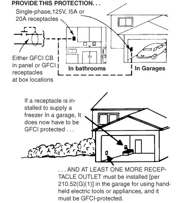
GFCI protection is required by 210.8 for all 125-V, single-phase, 15- and 20-A receptacles installed in bathrooms of dwelling units [part (A)(1)] and all other occupancies [part (B)(1)] and in garages of dwelling units (Fig. 210-15). The requirement for GFCI protection in “garages” is included because home owners do use outdoor appliances (lawn mowers, hedge trimmers, etc.) plugged into garage receptacles. Such receptacles require GFCI protection for the same reason as “outdoor” receptacles. In either place, GFCI protection may be provided by a GFCI circuit breaker that protects the whole circuit and any receptacles connected to it, or the receptacle may be a GFCI type that incorporates the components that give it the necessary tripping capability on low-level ground faults.
As just noted, GFCI protection is required by 210.8(B)(1) in bathrooms of all occupancies. This includes commercial office buildings, industrial facilities, schools, dormitories, theaters—bathrooms in ALL nondwelling occupancies. The rule here extends the same protection of GFCI breakers and receptacles to bathrooms in all nondwelling-type occupancies as for receptacles in bathrooms of dwelling units. It should be noted that there is no requirement to install a receptacle in bathrooms of other than dwelling units. But, if a 15- or 20-A, 125-V receptacle is installed in the bathroom of, say, an office building, then GFCI protection is required.
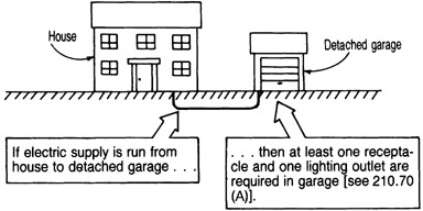
The rule of 210.8(A)(2) requiring GFCI protection in garages applies to both attached garages and detached (or separate) garages associated with “dwelling units”—such as one-family houses or multifamily houses where each unit has its own garage. In 210.52 the Code requires at least one receptacle in an attached garage and in a detached garage if electric power is run out to the garage.
Part (A)(2) of Sec. 210.8 says that 15- and 20-A receptacles in tool huts, workshops, storage sheds, and other “accessory buildings” with a “floor located at or below grade level” at dwellings must be GFCI-protected. In addition to requiring GFCI protection for receptacles installed in a garage at a dwelling unit, other outbuildings, such as tool sheds and the like, must have GFCI protection for all 15- and 20-A, 125-V receptacles. In the 1996 NEC, the rule only applied to receptacles installed at “grade level portions.” The rewording in the 1999 NEC requires GFCI protection for all 15- and 20-A, 125-V receptacles installed in an accessory building where the building has a floor that is “at or below grade level.” Obviously, that wording would eliminate the need for GFCI protection if the building’s floor is raised above “grade level,” such as by use of cinder blocks or stilts. Note, however, that the garage requirement applies wherever it is located in relation to grade level, even if you have to drive up a ramp.
It should be noted that this rule in no way requires a receptacle to be installed in such a building. But, where a 15- or 20-A, 125-V receptacle is installed in such a location and if the area is “not intended as (one or more) habitable rooms” but instead “limited to storage areas, work areas, and areas of similar use,” it must be GFCI-protected.
Note that the former exceptions for receptacles that were not readily accessible, such as for garage door openers, and single receptacles for dedicated uses such as freezers, have been entirely eliminated for the 2008 NEC edition. Any receptacle of the specified amperage and voltage and phasing as described must have GFCI protection. The panel made the decision that the reliability of these

Fig. 210-15. GFCI protection is required for receptacles in garages as well as in bathrooms. [Sec. 210.8(A)(2).]
devices has reached the point where special allowances need not be given. This is extremely controversial and time will be the judge of whether we are truly beyond the point where the consequences of and likelihood of a nuisance trip combine to justify the prior exceptions.
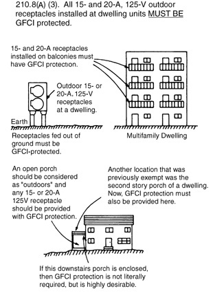
Part (A)(3) of Sec. 210.8, on outdoor receptacles, requires GFCI protection of all 125-V, single-phase, 15- and 20-A receptacles installed “outdoors” at dwelling units. Because hotels, motels, and dormitories are not “dwelling units” in the meaning of the Code definition, outdoor receptacles at such buildings do not require GFCI protection. The rule specifies that such protection of outdoor receptacles is required for all receptacles outdoors at dwellings (Fig. 210-16). The phrase “direct grade level access” was deleted from part (A)(3) a number of Code editions ago. Because the qualifier “grade level access” was deleted, apartment units constructed above ground level would need GFCI protection of receptacles installed outdoors on balconies. Likewise, GFCI protection would be required for any outdoor receptacle installed on a porch or other raised part of even a one-family house even though there is no “grade-level access” to the receptacle, as in the examples of Fig. 210-16.
The only exception to the rule of 210.8(A)(3) is for 15- and 20-A, 125-V receptacles that are installed to supply snow-melting and deicing equipment in accordance with Art. 426. Such a receptacle does not require GFCI protection as called for by Sec. 210.8(A)(3), but must have GFPE applied to the equipment as described in 426.28, provided it is installed on a dedicated circuit and in an inaccessible location. Under those circumstances to supply deicing and snow-melting equipment only, GFCI protection called for by this Code section may be omitted.
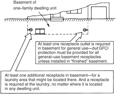
According to the rule of 210.8(A)(4) and (5), all 125-V, single-phase, 15- and 20-A receptacles installed in crawl spaces at or below grade and/or in unfinished basements must be GFCI-protected. This is intended to apply only to those basements or portions thereof that are unfinished (not habitable), and limited to “storage areas, work areas, and the like.” The rule of 210.52(G) requires that at least one receptacle outlet must be installed in the basement of a one-family dwelling, in addition to any installed for laundry equipment. The requirement that a receptacle be installed applies to basements of all one-family houses but not to apartment houses, hotels, motels, dormitories, and the like.
As in the case of garage locations, the former exceptions for dedicated use and for receptacles that were not readily accessible have been deleted, and for the same reasons. And here again this is very controversial, with particular concern registered around freezers and sump pumps. Here again, time will bring the verdict as to whether the reliability is there. Note that it is at least theoretically possible to hard-wire critical equipment and avoid the issue. Exception No. 3 specifically exempts receptacles supplying “fire alarm and burglar alarm systems” from the need for GFCI protection. However, such a receptacle must be a single receptacle. This is not a conventional line-voltage smoke detector setup; the exception refers to a full fire alarm control panel instead. The receptacle is powering the internal power supply and stand-by battery charger in the unit.
According to part (A)(6), GFCI protection is required for all 125-V, single-phase, 15- or 20-A receptacles installed in any kitchen of a dwelling unit where
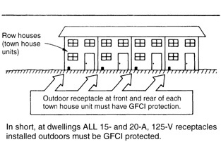
Fig. 210-16. For dwelling units, all outdoor receptacles require GFCI protection. [Sec. 210.8(A)(3).]
such receptacles are serving the countertop area. This will provide GFCI-protected receptacles for appliances used on countertops in kitchens in dwelling units. This would include any receptacles installed in the vertical surfaces of a kitchen “island” that includes countertop surfaces with or without additional hardware such as a range, grill, or even a sink. Because so many kitchen appliances are equipped with only 2-wire cords (toasters, coffee makers, electric fry pans, etc.), their metal frames are not grounded and are subject to being energized by internal insulation failure, making them shock and electrocution hazards. Use of such appliances close to any grounded metal—the range, a cooktop, a sink—creates the strong possibility that a person might touch the energized frame of such an appliance and at the same time make contact with a faucet or other grounded part—thereby exposing the person to shock hazard. Use of GFCI receptacles within the kitchen will protect personnel by opening the circuit under conditions of dangerous fault current flow through the person’s body (Fig. 210-17).
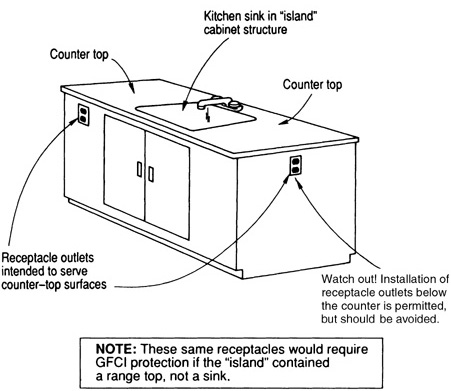
Fig. 210-17. GFCI protection must be provided for receptacles in kitchen. Receptacles in face of island cabinet structure in kitchen, if permitted, must be GFCI-protected. [Sec. 210.8(A)(6).]
Part (A)(7) requires that 15- and 20-A, 125-V countertop receptacles installed within 6 ft (1.8 m) of a laundry, utility, or wet bar sink be GFCI protected. Note that such receptacles may not be installed in the face-up position of the wet bar countertop, as covered in 406.4(E).
Although the requirement for GFCI protection of kitchen countertop receptacles is no longer based on their distance from the kitchen sink, the 6-ft (1.8 m) limitation is still the determining factor with wet bar countertop receptacles, or any receptacle located within 6 ft of a laundry, utility, or wet bar sink. Any 15- or 20-A receptacles installed within 6 ft (1.8 m) from the outside edge of a laundry, utility, or wet bar sink must be provided with GFCI protection.
210.8(A)(8) calls for GFCI protection of 15- and 20-A, 125-V rated receptacles installed at dwelling unit boathouses.
210.8(B). Other than Dwelling Units. These rules cover GFCI requirements for receptacles installed at commercial, industrial, and institutional occupancies. As given in (B)(1), all 15- and 20-A, 125-V rated receptacles installed in bathrooms of such occupancies must be GFCI protected. There is no requirement for the installation of receptacles in bathrooms of these occupancies, but if a receptacle is installed, this rule calls for GFCI protection of that receptacle.
Part (B)(2) requires GFCI protection for 15- and 20-A, 125-V rated receptacles installed in “kitchens”—regardless of accessibility or equipment supplied. The definition has been moved to Art. 100, and includes the phrase “with a sink and permanent facilities for preparing and cooking,” which excludes receptacles from the requirement for GFCI protection where installed in other areas of a commercial or institutional food service facility, such as a serving line or cafeteria area.
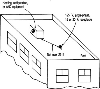
Part (B)(3) requires all 15- and 20-A, 125-V rooftop receptacles to be GFCI protected, and 210.8(B)(4) mandates GFCI protection for similar receptacles installed outdoors, now also in all locations regardless of accessibility. The only Exception to parts (3) and (4) eliminates the need for GFCI protection of receptacles installed to supply snow-melting or deicing equipment, provided the receptacles are “not readily accessible.” Note that since all outdoor and rooftop general purpose receptacles for nonresidential occupancies now require GFCI protection, there was no reason to continue the former requirement to protect the maintenance receptacle for heating, refrigeration, and air-conditioning equipment, so that provision has been deleted.
In its place is a new requirement [210.8(B)(5)] to protect any receptacle within 1.8 m (6 ft) of a sink, similar to the rule in 210.8(A)(7). This rule applies to all sinks of any description, not just laundry, utility, and wet bar sinks; however, it comes with an exception for receptacles adjacent to sinks in industrial laboratories where the removal of power could create a greater hazard. An example would be a receptacle adjacent to a lab hood sink for which a showing can be made that power to a mixer or other process is essential to the orderly, perhaps even nonexplosive, completion of reactions carried out in those locations.
A second exception exempts GFCI protections for receptacles near sinks in the patient care areas of hospitals, although the GFCI receptacle requirements in hospital bathrooms continue in effect. This allowance recognizes that in some areas, particularly in critical care areas, there will often be sinks within 6 ft of the “minimum of six receptacles” required by 517.19(B)(1). These receptacles require the very highest standard of reliability, and for that reason must be connected to two different supply sources (normal and emergency) from different transfer switches. An outage here could literally kill a critically ill patient reliant on life-support equipment of some sort that is plugged into one of these receptacles.
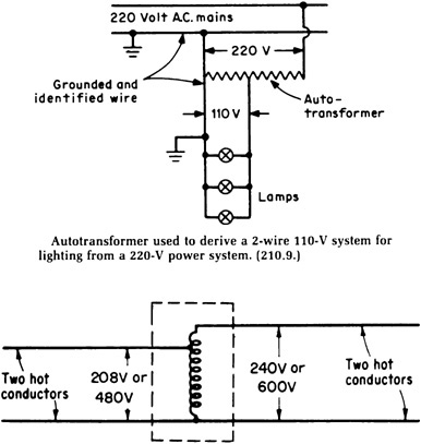
210.9. Circuits Derived from Autotransformers. The top of Fig. 210-18 shows how a 110-V system for lighting may be derived from a 220-V system by means of an autotransformer. The 220-V system either may be single phase or may be one leg of a 3-phase system. That hookup complies with the basic rule. In the case illustrated, the “supplied” system has a grounded wire solidly connected to a grounded wire of the “supplying” system: 220-V single-phase system with one conductor grounded.
Fig. 210-18. Autotransformers with and without grounded conductors are recognized. (Sec. 210.9, Exceptions No. 1 and No. 2.)
Autotransformers are commonly used to supply reduced voltage for starting induction motors.
Exception No. 1 permits the use of an autotransformer in existing installations for an individual branch circuit without connection to a similar identified grounded conductor where transforming from 208 to 240 V or vice versa (see Fig. 210-18). Typical applications are with cooking equipment, heaters, motors, and air-conditioning equipment. For such applications transformers are commonly used. This has been a long-established practice in the field of voltage ranges where a hazard is not considered to exist.
Buck or boost transformers are designed for use on single- or 3-phase circuits to supply 12/24 or 16/32-V secondaries with a 120/240-V primary. When connected as autotransformers the kVA load they will handle is large in comparison with their physical size and relative cost.
Exception No. 2 permits 480- to 600-V or 600- to 480-V autotransformers without connection to grounded conductor—but only for industrial occupancies with qualified maintenance and supervision. The reason for basic rule requiring continuity of a grounded circuit conductor has to do with predictability of voltage to ground. If the circuit in Fig. 210-18 is fed right to left (600 V ungrounded in, 480 V ungrounded out), and if the top conductor becomes grounded due to an insulation failure, the bottom conductor (common to both sides) will now be running 600 V to ground. This means that the 480 V derived system on the left will now run 480 V line-to-line, but 600 V to ground. The result is OK with appropriate supervision, and it has a very long track record of successful applications, but it must be taken into consideration at all times.
210.10. Ungrounded Conductors Tapped from Grounded Systems. This section permits use of 2-wire branch circuits tapped from the outside conductors of systems, where the neutral is grounded on 3-wire DC or single-phase, 4-wire, 3-phase, and 5-wire, 2-phase systems.
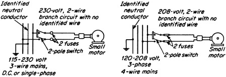
Figure 210-19 illustrates the use of unidentified 2-wire branch circuits to supply small motors, the circuits being tapped from the outside conductors of a 3-wire DC or single-phase system and a 4-wire, 3-phase wye system.
Fig. 210-19. Tapping circuits of ungrounded conductors from the hot legs of grounded systems. (Sec. 210.10.)
All poles of the disconnecting means used for branch circuits supplying permanently connected appliances must be operated at the same time. This requirement applies where the circuit is supplied by either circuit breakers or switches.
In the case of fuses and switches, when a fuse blows in one pole, the other pole may not necessarily open, and the requirement to “manually switch together” involves only the manual operation of the switch. Similarly, when a pair of circuit breakers is connected with handle ties, an overload on one of the conductors with the return circuit through the neutral may open only one of the circuit breakers; but the manual operation of the pair when used as a disconnecting means will open both poles. The words “manually switch together” should be considered as “operating at the same time,” that is, during the same operating interval, and apply to the equipment used as a disconnecting means and not as an overcurrent protective device.
Circuit breakers with handle ties are, therefore, considered as providing the disconnection required by this section. The requirement to “manually switch together” can be achieved by a “master handle” or “handle tie” since the operation is intended to be effected by manual operation. The intent was not to require a common trip for the switching device but to require that it have the ability to disconnect ungrounded conductors by one movement of the hand. For service disconnecting means, see Sec. 230-71.
210.11. Branch Circuits Required. After following the rules of 220.10 to ensure that adequate branch-circuit capacity is available for the various types of load that might be connected to such circuits, the rule in 210.11(A) requires that the minimum required number of branch circuits be determined from the total computed load, as covered in 220.10, and from the load rating of the branch circuits used.
For example, a 15-A, 120-V, 2-wire branch circuit has a load rating of 15 A times 120 V, or 1800 VA. If the load is resistive, like incandescent lighting or electric heaters, that capacity is 1800 W. If the total load of lighting that was computed from 220.12 were, say, 3600 VA, then exactly two 15-A, 120-V, 2-wire branch circuits would be adequate to handle the load, provided that the load on the circuit is not a “continuous” load (one that operates steadily for 3 h or more). Because 210.19(A) requires that branch circuits supplying a continuous load be loaded to not more than 80 percent of the branch-circuit rating, if the above load of 3600 VA was a continuous load, it could not be supplied by two 15-A, 120-V circuits loaded to full capacity. A continuous load of 3600 VA could be fed by three 15-A, 120-V circuits—divided among the three circuits in such a way that no circuit has a load of over 15 A times 120 V times 80 percent, or 2880 VA. If 20-A, 120-V circuits are used, because each such circuit has a continuous load rating of 20 times 120 times 80 percent, or 1920 VA, the total load of 3450 VA can be divided between two 20-A, 120-V circuits. The examples here use 120 V and not 115 or 110 V because 120 V is the standard voltage required to be used for load calculations in 220.5(A).
example Given the required unit load of 3 VA/sq ft for dwelling units (Table 220.12), the Code-minimum number of 20-A, 120-V branch circuits required to supply general lighting and general-purpose receptacles (not small appliance receptacles in kitchen, dining room, etc.) in a 2200-sq-ft one-family house is three circuits. Each such 20-A circuit has a capacity of 2400 VA. The required total circuit capacity is 2200 times 3 VA/sq ft, or 6600 VA. The next step is to divide 6600 by 2400, which equals 2.75. Thus, at least three such circuits would be needed.
example In 220.12, the NE Code requires a minimum unit load of 3 VA/sq ft for general lighting in a school, as shown in Table 220.12. For a small school of 1500 ft2, minimum capacity for general lighting would be
1500 ft2 × 3 VA/ft2 or 4500 VA
By using 120-V circuits, when the total load capacity of branch circuits for general lighting is known, it is a simple matter to determine how many lighting circuits are needed. By dividing the total load by 120 V, the total current capacity of circuits is determined:

But, because the circuits will be supplying continuous lighting loads (over 3 h), it is necessary to multiply that value by 1.25 in order to keep the load on any circuit to not more than 80 percent of the circuit rating. 37.5 × 1.25 = 46.9. Then, using either 15- or 20-A, 2-wire, 115-V circuits gives
which means four 15-A circuits, or

which means three 20-A circuits. And then each circuit must be loaded without exceeding the 80 percent maximum on any circuit.
Part (B) of 210.11 makes clear that a feeder to a branch-circuit panelboard and the main busbars in the panelboard must have a minimum ampacity to serve the calculated total load of lighting, appliances, motors, and other loads supplied. And the amount of feeder and panel ampacity required for the general lighting load must not be less than the amp value determined from the circuit voltage and the total voltamperes resulting from the minimum unit load from Table 220.12 (voltamperes per square foot) times the area of the occupancy supplied by the feeder—even if the actual connected load is less than the calculated load determined on the voltamperes-per-square-foot basis. (Of course, if the connected load is greater than that calculated on the voltamperes-per-square-foot basis, the greater value of load must be used in determining the number of branch circuits, the panelboard capacity, and the feeder capacity). Then, because this is actually a feeder calculation, the lighting loads determined by Table 220.12 then can be made subject to the demand factors in Table 220.42 as applicable for the specific occupancy.
It should be carefully noted that the first sentence of 210.11(B) states, “Where the load is computed on a voltamperes-per-square-foot basis, the wiring system up to and including the branch-circuit panelboard(s) shall be provided to serve not less than the calculated load.” Use of the phrase “wiring system up to and including” requires that a feeder must have capacity for the total minimum branch-circuit load determined from square-foot area times the minimum unit load (voltamperes per square foot from Table 220.12). And the phrase clearly requires that amount of capacity to be allowed in every part of the distribution system supplying the load. The required capacity would, for instance, be required in a sub-feeder to the panel, in the main feeder from which the subfeeder is tapped, and in the service conductors supplying the whole system (Fig. 210-20).
Actually, reference to “wiring system” in the wording of 210.11(B) presents a requirement that goes beyond the heading, “Branch Circuits Required,” of 210.11 and, in fact, constitutes a requirement on feeder capacity that supplements the rule of the second sentence of 215.2(A). This requires a feeder to be sized to have enough capacity for the load—as determined by part (A) of this article (which means, as computed in accordance with 220.10). However, as previously noted, the required feeder capacity can be reduced to the extent the NEC permits for the feeder in question.
Fig. 210-20. Capacity must be provided in service and feeder conductors, as well as a branch-circuit panelboard that is adequate for the calculated load.
The second part of 210.11(B) affects the required minimum number of branch circuits. Although the feeder and panelboard must have a minimum capacity to serve the calculated load, it is only necessary to install the number of branch-circuit overcurrent devices and circuits required to handle the actual connected load in those cases where it is less than the calculated load. The last sentence of 210.11(B) is clearly an exception to the basic rule of the first sentence of 210.11(A), which says that “The minimum number of branch circuits shall be determined from the total computed load. . . .” Instead of having to supply that minimum number of branch circuits, it is necessary to have only the number of branch circuits required for the actual total “connected load.” However, the branch-circuit panelboard would also need to have sufficient space to install the numbers of circuits calculated, because that panel is part of the wiring system at the feeder level.
example For an office area of 200 × 200 ft, a 3-phase, 4-wire, 480/277-V feeder and branch-circuit panelboard must be selected to supply 277-V HID lighting that will operate continuously (3 h or more). The actual continuous connected load of all the lighting fixtures is 92 kVA. What is the minimum size of feeder conductors and panelboard rating that must be used to satisfy Sec. 210.11(B)?
200 ft × 200 ft = 40,000 sq ft
40,000 sq ft @ minimum of 3.5 VA/sq ft = 140,000 VA
The minimum computed load for the feeder for the lighting is
140,000 VA ÷ [(480 V)(1.732)] = 168 A per phase
The actual connected lighting load for the area, calculated from the lighting design, is
92,000 VA ÷ [(480 V)(1.732)] = 111 A per phase
Sizing of the feeder and panelboard must be based on 168 A, not 111 A, to satisfy 210.11(B). The next step is to correlate the rules of Sec. 210.11(A) and (B) with those of 215.2(A)(1). The rule of 215.2(A)(1) requires a feeder to be sized for the “computed load” as determined by parts II, III, and IV in Art. 220. Because the entire lighting load is assumed to operate continuously in this type of occupancy, the feeder to supply the continuous calculated load of 168 A must have an ampacity at least equal to that load times 1.25. This is not for the sake of the wire, whose ampacity is by definition a continuous current-carrying capacity expressed in amperes. This is for the sake of the internal calibration of a conventional circuit breaker, which requires the heat sink effect of a cooler wire bolted to it. Therefore, 215.2(A)(1) assures that in any load calculation under conditions of continuous loading, a phantom capacity will be built into the feeder size. Further, 110.14(C)(1)(b) requires that the terminations on the circuit breaker be made based on wire sizes evaluated under the 75°C column of Table 310.16. This is true whenever using a CB or fused switch that is not UL-listed for continuous operation at 100 percent of rating, as required in 215.3. Finally, since this 3-phase, 4-wire feeder will be feeding predominantly electric discharge lighting with a strong triplen harmonic content, 310.15(B)(4)(c) will require that the neutral be counted as current carrying, and with four wires carrying current in the same raceway, 310.15(B)(2)(a) will then impose a 80 percent derating factor on the feeder conductors for mutual conductor heating.
168 A × 1.25 = 210 A [215.2(A)(1)]
1. Assuming use of a non-100 percent rated protective device, the overcurrent device must be rated not less than 1.25 × 168 A, or 210 A—which calls for a standard 225-A circuit breaker or fuses (the standard rating above 210 A).
2. Although feeder conductors with an ampacity of 210 A would satisfy the rule of 215.2(A) and be adequate for the load, they might not be properly protected (240.4) by a 225-A device after derating. The feeder must have a 75°C table ampacity that is not less than 210 A (168 A × 1.25) before derating but must also be properly protected by the 225-A rated device after derating. Additional calculations are required to make a final determination.
3. Using Table 310.16, the smallest size of feeder conductor that would be protected by 225-A protection after 80 percent derating for number of conductors is a No. 4/0 THHN or XHHW copper, with a 230 A value in the 75°C column and a 90°C ampacity of 260 A before derating (260 A × 0.8 = 208 A). Remember: To satisfy 215.2(A)(1), the 75°C column is used. And, where 90°C-insulated conductors are used, any “deratings” needed may be applied against the ampacity value shown in the 90°C column in Table 310.16.
4. Because the UL and 110.14(C)(1)(b) requires that conductors larger than No. 1 AWG must be used at no more than their 75°C ampacities to limit heat rise in equipment terminals, the selected No. 4/0 THHN or XHHW copper conductor must not operate at more than 230 A—which is the table value of ampacity for a 75°C No. 4/0 copper conductor. And the load current of 168 A is well within that 230 A maximum. Further, the 225-A circuit breaker will protect the 4/0 feeder conductors under the conditions of use, because the final ampacity of these conductors is 208 A and a 225-A overcurrent device is the next higher standard size, allowable in these size ranges by 240.4(B).
Thus, all requirements of 215.2(A) and UL are satisfied.
5. Note that the minimum feeder size came out 210 A, and the ampacity of the feeder conductors chosen came out 208 A in item 3 above. To some, this may look like the feeder size needs to be further increased, but not so. Comparing these two numbers is comparing apples and oranges. The required feeder size to overcome mutual conductor heating in distant parts of the feeder raceway is one calculation, involving the middle of the wire. And it turns out that a 4/0 feeder will carry this load safely because under the conditions of use its ampacity (continuous load capacity) is 208 A, although actually loaded to 168 A. Further, the same size wire will fulfill its heat sink responsibilities at the circuit breaker terminals because, using the 75°C column of Table 310.16, the ampacity of this wire is 230 A, and all it needs to be, inclusive of the required 25 percent phantom loading, is 210 A. These two calculations are entirely independent and should be done on separate pieces of paper.
6. The calculation of ampacities for conductors carrying continuous loads under non-standard conditions of use and correlating those calculations with other rules on allowable terminating sizing involves some of the most complex analysis of any Code application. Any such analysis involves integrating key general rules in the first three chapters of the NEC together with specific application provisions in the remainder of the NEC. For this reason, and because the end of the Code, in Annex D Example 3(a), contains a fully developed example of one of these calculations fully worked out, line-by-line and with all applicable NEC provisions specifically cited, a full explanation of this calculation process will be reserved for the end of the book. Refer to Chap. 9 for this information.
The rule in 408.30 requires the panelboard here to have a rating not less than the loads as calculated in Art. 220—which, in this case, means the panel must have a busbar rating not less than 168 A. Since the bus assembly must, in this case, be assumed to be distributing this load on a continuous basis, the 125 percent rule in 215.2(A)(1) will apply here as well, resulting in a minimum bus size of 210 A. A 225-A panelboard (i.e., the next standard rating of panelboard above the minimum calculated value of load current—210 A) is therefore required, even though it might seem that a 125-A panel would be adequate for the actual load current of 111 A.
The number of branch-circuit protective devices required in the panel (the number of branch circuits) is based on the size of branch circuits used and their capacity related to connected load. If, say, all circuits are to be 20-A, 277-V phase-to-neutral, each pole may be loaded not more than 16 A because 210.19(A)(1) requires the load to be limited to 80 percent of the 20-A protection rating. With the 111 A of connected load per phase, a single-circuit load of 16 A calls for a minimum of 111 ÷ 16, or 8 poles per phase leg after rounding up. Thus a 225-A panelboard with 24 breaker poles would satisfy the rule of 210.11(B).
Part (C)(1) of 210.11 requires that two or more 20-A branch circuits be provided to supply all the receptacle outlets required by 210.52(B) in the kitchen, pantry, dining room, breakfast room, and any similar area of any dwelling unit—one-family houses, apartments, and motel and hotel suites with cooking facilities or serving pantries. That means that at least one 3-wire, 20-A, 240/120- or 208/120-V circuit shall be provided to serve only receptacles for the small-appliance load in the kitchen, pantry, dining room, and breakfast room of any dwelling unit. Of course, two 2-wire, 20-A, 120-V circuits are equivalent to the 3-wire circuit and could be used. If a 3-wire, 240/120-V circuit is used to provide the required two-circuit capacity for small appliances, the 3-wire circuit can be split-wired to receptacle outlets in these areas, provided a common disconnecting means is installed to meet 210.4(B) and 210.7(B).
Part (C)(2) of 210.11 requires that at least one 20-A branch circuit be provided for the one or more laundry receptacles installed, as required by 210.52(F), at the laundry location in a dwelling unit. Further, the last sentence of part (C)(2), in conjunction with 210.52(F), prohibits use of the laundry circuit for supplying outlets that are not for laundry equipment. Receptacle outlets for the laundry must be located at any anticipated laundry equipment locations because 210.50(C) requires them to be within 6 ft (1.8 m) of the intended appliance location (Fig. 210-21).
Fig. 210-21. No “other outlets” are permitted on 20-A circuit required for laundry receptacles. [Sec. 210.11(C).]
Part (C)(3) of 210.11 requires a dedicated branch circuit to supply receptacle outlets within a dwelling unit’s bathrooms. This must be a 20-A circuit, and it may supply receptacles in bathrooms only! The wording recognizes supplying more than one bathroom from a single 20-A circuit. And the Exception allows limited installation of “other” outlets on this circuit where the circuit supplies only a single bathroom. So the basic rule puts all bathroom receptacles on a single circuit, or more, provided such circuits serve only bathroom receptacles. Then, as a trade-off, a 20-A circuit can supply all the loads in a bathroom, but as soon as it serves some load other than a receptacle, it must serve only a single bathroom. This exception allows for a simple and practical method of complying with listing instructions that often apply to exhaust fans over a tub, where they will generally require GFCI protection. Use the exception, and make sure that the fan is on the load side of the receptacle. Of course at this point all the wiring in a bath wired this way would need to be 12 AWG to match the 20-A circuit configuration.
210.12. Arc-Fault Circuit Interrupter Protection. The arc-fault circuit interrupter (AFCI) devices are similar to, but different from, the more commonly recognized GFCIs. But while the GFCI operates on the basis that any current difference between the hot and the neutral (or the hot and the hot for 250-V single-phase devices) greater than 5 mA is “unauthorized” current flow to ground, causing it to open the circuit under such conditions, the AFCI operates to open the circuit either on a low-level current imbalance exceeding about 30 mA or when it senses a specific waveform anomaly that is indicative of an arcing fault.
Advances in electronics have made it possible for the internal chip to recognize the specific waveform characteristics of an arcing-type fault and to operate a mechanical ratchet to open the circuit, thereby providing a greater level of protection against the potential for shock, electrocution, and property damage that these typically high-impedance, low-current malfunctions can present.
There are two broad classifications of arcing failures that can be addressed by AFCI technology, namely, a line-to-line or line-to-ground failure that can occur in parallel with a connected load or even with no energized load in operation, or a failure between two severed ends of the same conductor, or at a poor connection point for such a conductor, either one in series with a connected load. The first AFCI devices in wide usage, configured as an additional tripping provision in certain circuit breakers (and designated as “Branch/Feeder AFCIs” by UL), addressed the more common parallel events only, and the NEC permitted the use of this more limited protection until January 1, 2008. Meanwhile, the only design that addressed the series failure was configured as part of a duplex receptacle akin to a GFCI receptacle. These are designated by UL as an “Outlet/Branch Circuit AFCI,” and if located as the first outlet on a branch circuit, provide series protection for the entire branch circuit and parallel protection for all downstream portions of the circuit.
The “outlet/branch-circuit” devices have not, as of this writing been commercially manufactured although prototypes exist and at least one manufacturer has a listing. The reason for this is the restrictive nature of the NEC conditions for which such a device is permitted to qualify as the required AFCI protection for a branch circuit. Under the 2005 NEC the device had to be located not over 6 ft from the point of branch circuit origination with the distance to be measured along the conductors, and metallic wiring methods employed between the two locations. Under the 2008 NEC, the distance can be of any length, but the wiring methods must be steel, either as a cable assembly (e.g., steel Type AC, but not the usual Type MC with aluminum armoring) or as one of three specified steel tubular raceways (IMC, RMC, or EMT) but not, technically, wireways or other wiring methods even if made of steel. It remains to be seen whether this will be a sufficient concession to bring these devices to market. Wiring to a fire alarm system can omit AFCI protection entirely, provided the same wiring methods are used. Remember that this reference is to a full red-box fire alarm control panel governed by Art. 760, and not the usual 120 V reciprocally alarming residential smoke detector installation.
Effective January 1, 2008 under the 2005 NEC, and also as incorporated into the 2008 NEC, AFCI protective devices must combine the best protective features of both parallel and series protective devices. These devices are what the NEC refers to as “combination-type” to refer to both parallel and series arcing failures. This designation has nothing to do with a device that provides both AFCI and GFCI protection, although the technology is mutually compatible, and devices that provide both shock protection and arc-fault mitigation are available from some manufacturers.
Arc-fault circuit interrupters are now required (2008 NEC) to protect all circuits that supply outlets (receptacle and lighting) in dwelling unit family rooms, dining rooms, living rooms, parlors, libraries, dens, bedrooms, sun-rooms, recreation rooms, closets, hallways, or similar rooms or areas. Most receptacle outlets in bathrooms, basements, kitchens, garages, and outdoors require GFCI protection. The result is that virtually every outlet in a dwelling unit must now have some form of residual current detection, and in most areas a failure in the branch-circuit wiring itself will also be detected and opened. Although it would be theoretically possible to omit protection of a lighting circuit that only served a kitchen or bathroom or both, as a practical matter all general-purpose lighting and receptacle outlets throughout the entire dwelling must be protected on installations governed by the 2008 NEC and thereafter.
Not all manufacturers are currently making two-pole AFCI circuit breakers, although that will probably change with time. This is important because, just as in the case of GFCI protection, a two-pole device is required to be used with a multiwire branch circuit. Some, but not all manufacturers make AFCIs in bolton configurations frequently specified for commercial and multifamily residential applications. Of course, the bolt-on configuration can be used anywhere but it is more prevalent in the larger quasi-commercial applications. Until the supply chain becomes completely up to speed on current applications, this will be an issue, particularly on retrofits. Note that at least one manufacturer of two-pole AFCIs also makes classified AFCI circuit breakers that are rated for a number of competitors’ panels, so that could be another way out for now. Note that such classification ratings are limited to some extent, particularly for applications involving available fault currents over 10 kA.
210.18. Guest Rooms and Guest Suites. A guest room in a hotel or motel, if it contains permanent provisions for cooking, must meet all the rules for outlet circuiting and receptacle placements that a dwelling unit must meet. A plug-in microwave oven wouldn’t, by itself, trigger this classification, but a permanent cooktop certainly would. If so, the guest room or suite would be subject to AFCI coverage, no fewer than two small-appliance branch circuits, etc.
210.19. Conductors—Minimum Ampacity and Size. In past NEC editions, the basic rule of this section has said—and still does say—that the conductors of a branch circuit must have an ampacity that is not less than the maximum current load that the circuit will supply. Obviously, that is a simple and straightforward rule to ensure that the conductors are not operated under overload conditions. But, where the load to be served is “continuous,” other concerns must be addressed.
210.19(A)(1). General. Part (A)(1) of this section says that branch circuit wiring supplying a continuous current load must have an ampacity (the current-carrying capacity expressed in amperes as evaluated under the conditions of use) not less than 125 percent of the continuous-current load portion of the circuit, plus any noncontinuous load. The idea of the rule is that 125 percent of a total continuous-load current portion of the circuit plus the noncontinuous load gives a circuit rating such that the continuous-load current does “not exceed 80 percent of the rating of the branch circuit evaluated after subtracting the noncontinuous load.” One is the flip side of the other. (See Fig. 210-22 for a simple application.)
Fig. 210-22. Branch-circuit protective device must be rated not less than 125 percent of the continuous load current. [Sec. 210.19(A).]
The first exception covers an overcurrent device including the assembly in which it is installed that has been listed for operation at 100 percent of its rating for continuous duty. In such cases there is no derating for the continuous portion of the load. Remember that the ampacity of a conductor reflects its ability to carry current on a continuous basis. Continuous loads do not bother conductors, but they do cause problems with overcurrent devices and the NEC builds in additional capacity in the circuit wiring so, where it is connected to the overcurrent device, it will be cool and capable of providing a heat sink for the device to which it is connected. A 100 percent-rated device does not require this feature.
Note, however, that as a practical matter this allowance will never be used for branch circuits. The smallest circuit breaker with this capability has a 600-A frame size and tripping elements set for 100 or 125 A, depending on the manufacturer. Although there are industrial applications for this provision, the far more common application will be on feeder circuits. This book includes extensive coverage of this topic in its coverage of Art. 215.
There is a second exception at this point that waives the upsizing requirement for grounded conductors that are not connected to an overcurrent device, on the basis that a neutral busbar does not require a heat sink to work properly under continuous operating conditions. Although this is certainly correct, the grounded circuit conductor in question has two ends, and the equipment to which its other end is connected may not be equally forgiving. This is new in the 2008 NEC, having been added both here and in the feeder article. In the case of a feeder, where the grounded conductor usually connected busbar to busbar, there is no issue with this concept, but on branch circuits it may be better to stay with an upsized conductor until this is sorted out. Certainly the device or equipment manufacturer should be consulted to see how the end use products were tested.
The entire process of correlating NEC rules for continuously loaded conductors with the requirements for derating and with the restrictions on conductor sizing at terminations is very possibly the most complicated calculation process in the NEC, and also one of the most essential to learn correctly. After all, what do electricians do but select and install wires? Because this process involves rules from many different locations in the code, and because the NEC now includes a comprehensive example written by this author that correlates this information, please refer to the discussion at the end of this book on Annex D, Example D3(a) for a systematic walk-through of how to apply the rules. They are not simple, but there are some basic principles to keep you on the right track, such as every wire having a middle and two ends and not confusing the rules that apply to one part of a circuit with rules that apply only to another part.
This part of 210.19(A) concludes with a fine-print note addressing voltage drop. This topic is fully addressed in this book in its coverage of Art. 215.
The wording of the rule in 210.19(A)(2) requires the circuit conductors to have an ampacity not less than “the rating of the branch circuit” only for a multioutlet branch circuit that supplies receptacles for cord- and plug-connected loads. The concept here is that receptacles provide for random, indeterminate loading of the circuit; and, by matching conductor ampacity to the amp rating of the circuit fuse or CB, overloading of the conductors can be avoided. But for multioutlet branch circuits that supply fixed outlets—such as lighting fixture outlets or hard-wired connections to electric heaters or other appliances—it is acceptable to have a condition where the conductor ampacity is adequate for the load current. But where there is no standard rating of protective device that corresponds to the conductor ampacity, the circuit fuse or CB rating is the next higher standard rating of protective device above the ampacity value of the conductor (Fig. 210-23).
The receptacle limitation almost correlates with 240.4(B)(1), which disallows the use of the familiar next-higher-standard-size-device permission for circuits that supply multiple receptacle outlets, but not quite. This rule [210.19(A)(2)] requires fully sized conductors if more than one receptacle is supplied by the branch circuit; the rule in 240.4(B)(1) applies when more than one receptacle outlet is supplied. A review of the definition of the word “receptacle” in Art. 100 shows that if you consider a circuit with just one duplex receptacle, the rule in 210.19(A)(2) requires fully sized branch circuit conductors, but the wording in 240.4(B)(1) would allow the next higher standard size overcurrent device to be used. This gets even more complicated because although the rule in 210.19(A)(2) applies to plural receptacles, the title of the paragraph conflicts with the rule because it describes the coverage in terms of plural outlets. As always the local inspector will have to make the call, in this case determining whether the limitation should apply to outlets or devices.
Fig. 210-23. This is the basic rule for any multioutlet branch circuit supplying one or more receptacles. [Sec. 210.19(B).]
For multioutlet branch circuits (rated at 15, 20, 30, 40, or 50 A), the ampacities of conductors usually correspond to standard ratings of protective devices when there is only one circuit in a cable or conduit. But when circuits are combined in a single conduit so that more than three current-carrying conductors are involved, the ampacity derating factors of Table 310.15(B)(2) often result in reduced ampacity values that do not correspond to standard fuse or CB ratings. It is to such cases that the rule of 210.19(A)(2) may be applied.
For instance, assume that two 3-phase, 4-wire multioutlet circuits are run in a single conduit. Two questions arise: (1) How much load current may be put on the conductors? and (2) What is the maximum rating of overcurrent protection that may be used for each of the six hot legs? Evaluate this problem assuming that the outlets supply receptacle outlets, and then evaluate it again assuming that the circuit supplies fluorescent lighting.
The eight wires in the single conduit (six phases and two neutrals) must be taken as eight conductors when applying 310.15(B)(2) because the neutrals to electric-discharge lighting carry harmonic currents and must be counted as current-carrying conductors [310.15(B)(4)(c)]. Table 310.15(B)(2) then shows that the No. 14 wires must have their ampacity reduced to 70 percent (for 7 to 9 wires) of the 20-A ampacity given in Table 310.16 for No. 14 TW. With the eight No. 14 wires in the one conduit, then, each has an ampacity of 0.7 × 20, or 14 A. Because 210.19(A)(2) requires circuit wires to have an ampacity at least equal to the rating of the circuit fuse or CB if the circuit is supplying receptacles, use of a 15-A fuse or 15-A circuit breaker would not be acceptable in such a case because the 14-A ampacity of each wire is less than “the rating of the branch circuit” (15 A) if more than one receptacle is supplied. On the other hand, if the circuits here are supplying fixed lighting outlets, 210.19(A)(2) would not apply and 210.19(A)(1) would accept the 15-A protection on wires with 14-A ampacity. In such a case, it is not only necessary that the design load current on each phase must not exceed 14 A, but if the lighting load is continuous (operating steadily for 3 h or more), the load on each 15-A CB or fuse must not exceed 0.8 × 15, or 12 A [as required by 210.19(A)(1)].
In part (A)(3), the rule also calls for the same approach to sizing conductors for branch circuits to household electric ranges, wall-mounted ovens, counter-mounted cooking units, and other household cooking appliances (Fig. 210-24).
Fig. 210-24. Sizing circuit conductors for household electric range. [Sec. 210.19(A)(3).]
The maximum demand for a range of 12-kW rating or less is sized from NEC Table 220.55 as a load of 8 kW. And 8000 W divided by 240 V is approximately 33 A. Therefore, No. 8 conductors with an ampacity of 40 A may be used for the range branch circuit.
On modern ranges the heating elements of surface units are controlled by five-heat unit switches. The surface-unit heating elements will not draw current from the neutral unless the unit switch is in one of the low-heating positions. This is also true to a greater degree as far as the oven-heating elements are concerned, so the maximum current in the neutral of the range circuit seldom exceeds 20 A. Because of that condition, Exception No. 2 permits a smaller-size neutral than the ungrounded conductors, but not smaller than No. 10.
A reduced-size neutral for a branch circuit to a range, wall-mounted oven, or cooktop must have ampacity of not less than 70 percent of the circuit rating, which is determined by the current rating or setting of the branch-circuit protective device. This is a change from previous wording that required a reduced neutral to have an ampacity of at least 70 percent of “the ampacity of the ungrounded conductors.” Under that wording, a 40-A circuit (rating of protective device) made up of No. 8 TW wires for the hot legs could use a No. 10 TW neutral—because its 30-A ampacity is at least 70 percent of the 40-A ampacity of a No. 8 TW hot leg (0.7 × 40 A = 28 A). But if No. 8 THHN (55-A ampacity) is used for the hot legs with the same 40-A protected circuit, the neutral ampacity would have to be at least 70 percent of 55 A (0.7 × 55 A = 38.5 A) and a No. 10 TW (30 A) or a No. 10 THW (35 A) could not have been used. The newer wording bases neutral size at 70 percent of the protective-device rating (0.7 × 40 A = 28 A), thereby permitting any of the No. 10 wires to be used, and does not penalize use of higher-temperature wires (THHN) for the hot legs.
Exception No. 1 permits taps from electric cooking circuits (Fig. 210-25). Because Exception No. 1 says that taps on a 50-A circuit must have an ampacity of at least 20 A, No. 14 conductors—which have an ampacity of 20 A in Table 310.16—may be used.
Fig. 210-25. Tap conductors may be smaller than wires of cooking circuit. [Sec. 210.19(A)(3), Exception No. 1.]
Exception No. 1 applies to a 50-A branch circuit run to a counter-mounted electric cooking unit and wall-mounted electric oven. The tap to each unit must be as short as possible and should be made in a junction box immediately adjacent to each unit. The words “not longer than necessary for servicing the appliance” mean that it should be necessary only to move the unit to one side in order that the splices in the junction box become accessible.
210.19(A)(4) sets No. 14 as the smallest size of general-purpose circuit conductors. But tap conductors of smaller sizes are permitted as explained in Exceptions No. 1 and No. 2 (Fig. 210-26). No. 14 wire, not longer than 18 in. (450 mm), may be used to supply an outlet unless the circuit is a 40- or 50-A branch circuit, in which event the minimum size of the tap conductor must be No. 12.
The wording of 210.19(A)(4), Exception No. 1, specifically excludes receptacles from being installed as indicated here because they are not tested for such use. That is, when tested for listing, receptacles are not evaluated using 18-in. (450-mm) taps of the size specified in Table 210.24 and protected as indicated by 210.19(A)(4), Exception No. 1. As a result, receptacles have been prohibited from being supplied by tap conductors, as is permitted by this exception for other loads. It is not permitted to install 14 AWG pigtails on receptacles connected to 20-A branch circuits.
210.20. Overcurrent Protection. The previous section covered the minimum size of a wire used in a branch circuit; this covers the permitted size of a branch-circuit overcurrent protective device. And here again, the overcurrent device must be rated at not less than 125 percent of any continuous loading plus 100 percent of any noncontinuous loading. This is another example of a code rule that requires correlation while making calculations so as to be certain that all requirements are satisfied. Refer to the detailed discussion at the end of this book [Annex D, Example D3(a)] where all the concepts are integrated.
Fig. 210-26. Tap conductors may be smaller than circuit wires. [Sec. 210.19(A)(3), Exception Nos. 1 and 2.]
210.21. Outlet Devices. Specific limitations are placed on outlet devices for branch circuits: Lampholders must not have a rating lower than the load to be served; and lampholders connected to circuits rated over 20 A must be heavy-duty type (i.e., rated at least 660 W if it is an “admedium” type and at least 750 W for other types). Because fluorescent lampholders are not of the heavy-duty type, this excludes the use of fluorescent luminaires on 30-, 40-, and 50-A circuits. The intent is to limit the rating of lighting branch circuits supplying fluorescent fixtures to 20 A. The ballast is connected to the branch circuit rather than the lamp, but by controlling the lampholder rating, a 20-A limit is established for the ballast circuit. Most lampholders manufactured and intended for use with electric-discharge lighting for illumination purposes are rated less than 750 W and are not classified as heavy-duty lampholders. If the luminaires are individually protected, such as by a fuse in the cord plug of a luminaire cord connected to, say, a 50-A trolley or plug-in busway, some inspectors have permitted use of fluorescent luminaires on 30-, 40-, and 50-A circuits. But such protection in the cord plug or in the luminaire is supplementary (240.10), and branch-circuit protection of 30-, 40-, or 50-A rating would still exclude use of fluorescent fixtures according to 210.21(A). High-intensity discharge lighting such as metal-halide luminaires frequently incorporates heavy duty mogul-base lampholders and would not be limited by this rule.
210.21(B) contains four paragraphs of importance. Part (B)(1) reads: “A single receptacle installed on an individual branch circuit shall have an ampere rating of not less than that of the branch circuit.” Since the branch-circuit overcurrent device determines the branch-circuit rating (or classification), a single receptacle (not a duplex receptacle) supplied by an individual branch circuit cannot have a rating less than the branch-circuit overcurrent device, as shown in Fig. 210-27. Exceptions apply for specialized applications where the single receptacle configuration must correlate with motor rules in one case and with the inherently special short-time usages associated with welders in the other.
Fig. 210-27. Receptacle amp rating must not be less than circuit protection rating for an individual circuit. [Sec. 210.21(B).]
Part (B)(2) requires that receptacles installed in multiple on a branch circuit, including just one duplex receptacle installed on a branch circuit with only the one outlet, must not have a cord-and-plug connected load in excess of 80 percent of the receptacle rating. Per Part (B)(3), on circuits having two or more receptacles or outlets, receptacles shall be rated as follows:
On 15-A circuits—not over 15-A rating
On 20-A circuits—15- or 20-A rating
On 30-A circuits—30-A rating
On 40-A circuits—40- or 50-A rating
On 50-A circuits—50-A rating
Note that on 15-A circuits, a 20-A configured receptacle is not permitted, even though a 15-A receptacle is permitted on a 20-A circuit (unless it is a single receptacle on an individual branch circuit). The Code entitles any user to believe that if a 20-A plug will fit into the receptacle, the circuit will have the capability of safely supplying that load. Exceptions apply in instances where a multioutlet branch circuit is used for multiple cord-and-plug-connected welders (to correlate with Art. 630) and for electric discharge lighting applications where a receptacle rating of not less than 125 percent of the load is sufficient. For multioutlet branch circuits rated over 50 A, as permitted under the limited conditions described in the discussion on the Exception to 210.3, every receptacle must have a rating not less than the branch-circuit rating. Part (D)(4) allows range receptacle configurations to use the same Table 220.55 loading calculations as other elements of the circuit.
210.23. Permissible Loads. A single branch circuit to one outlet or load may serve any load and is unrestricted as to amp rating. Circuits with more than one outlet are subject to NE Code limitations on use as follows. (The word “appliance” stands for any type of utilization equipment.)
1. Branch circuits rated 15 and 20 A may serve lighting units and/or appliances. The rating of any one cord- and plug-connected appliance shall not exceed 80 percent of the branch-circuit rating. Appliances fastened in place may be connected to a circuit serving lighting units and/or plug-connected appliances, provided the total rating of the fixed appliances fastened in place does not exceed 50 percent of the circuit rating (Fig. 210-28). Example: 50 percent of a 15-A branch circuit = 7.5 A. A permanently connected ventilating fan/light combination installed in a bathroom ceiling and drawing, say, 2.5 A, is permitted to be connected to a lighting circuit. However, the same appliance configured with a heating element drawing an additional 9 A could not be connected to the aforementioned lighting circuit. However, no hard-wired loads, such as range hoods or other appliances, regardless of current draw, are permitted to be connected to the specialized appliance circuits covered in 210.11(C). The bathroom receptacle circuits, the small-appliance branch circuits, and the laundry circuits are entirely reserved for cord-and-plug connected loads in the designated areas.
Fig. 210-28. General-purpose branch circuits—15 or 20 A. [Sec. 210.23(A).]
However, modern design usually provides separate circuits for individual fixed appliances of any significant load. In commercial and industrial buildings, separate circuits should be provided for lighting and separate circuits for receptacles.
2. Branch circuits rated 30 A may serve fixed lighting units (with heavy-duty-type lampholders) in other than dwelling units or appliances in any occupancy. Any individual cord- and plug-connected appliance which draws more than 24 A may not be connected to this type of circuit (Fig. 210-29).
Because an individual branch circuit—that is, a branch circuit supplying a single outlet or load—may be rated at any ampere value, it is important to note that the omission of recognition of a 25-A multioutlet branch circuit does not affect the full acceptability of a 25-A individual branch circuit supplying a single outlet. A typical application of such a circuit would be use of No. 10 TW aluminum conductors (rated at 25 A in Table 310.16), protected by 25-A fuses or circuit breaker, supplying, say, a 4500-W water heater at 240 V. The water heater is a load of 4500 ÷ 240, or 18.75 A, which is taken as 19 A per 220.5(A). Then, because 422.13 designates water heaters as continuous loads (in tank capacities up to 120 gal), the 19-A load current multiplied by 125 percent equals 24 A and satisfies 422.10(A) on the required minimum branch-circuit rating. The 25-A rating of the circuit overcurrent device also satisfies 422.11(E)(3), which says that the overcurrent protection must not exceed 150 percent of the ampere rating of the water heater. Note that although the 25-A circuit is permitted in this case, a 30-A circuit is also permitted, and far more common. The 19-A load applied at 150 percent is just under 30 A, and the next-higher-standard sized protective device is permitted.
Fig. 210-29. Multioutlet 30-A circuits. [Sec. 210.23(B).]
3. Branch circuits rated 40 and 50 A may serve fixed lighting units (with heavy-duty lampholders) or infrared heating units in other than dwelling units or cooking appliances in any occupancy (Fig. 210-30). It should be noted that a 40- or 50-A circuit may be used to supply any kind of load equipment—such as a dryer or a water heater—where the circuit is an individual circuit to a single appliance. The conditions shown in that figure apply only where more than one outlet is supplied by the circuit. Figure 210-31 shows the combination of loads.
4. A multioutlet branch circuit rated over 50 A—as permitted by 210.3—is limited to use only for supplying industrial utilization equipment (machines, welders, etc.) and may not supply lighting outlets.
Except as permitted in 660.4 (and 517.71 for medical purposes) for portable, mobile, and transportable medical x-ray equipment, branch circuits having two or more outlets may supply only the loads specified in each of the preceding categories. It should be noted that any other circuit is not permitted to have more than one outlet and would be an individual branch circuit.
It should be noted that the requirement calling for heavy-duty type lampholders for lighting units on 30-, 40-, and 50-A multioutlet branch circuits excludes the use of fluorescent lighting on these circuits because lampholders are not rated “heavy-duty” in accordance with 210.21(A) (Fig. 210-32). High-intensity discharge units with mogul lampholders may be used on these circuits provided tap conductor requirements are satisfied.

Fig. 210-30. Larger circuits. [Sec. 210.23(C).]
210.24. Branch-Circuit Requirements—Summary. Table 210.24 summarizes the requirements for the size of conductors where two or more outlets are supplied. The asterisk note also indicates that these ampacities are for copper conductors where derating is not required. Where more than three conductors are contained in a raceway or a cable, 310.15(B)(2) specifies the load-current derating factors to apply for the number of conductors involved. A 20-A branch circuit is required to have conductors which have an ampacity of 20 A and also must have the overcurrent protection rated 20 A where the branch circuit supplies two or more outlets. Refer to the detailed discussion of conductor ampacity and load-current limits covered at Annex D, Example D3(a).
Fig. 210-31. Only specified loads may be used for multioutlet circuit. [Sec. 210.23(C).]
Fig. 210-32. Watch out for this limitation on fluorescent equipment. (Sec. 210.23.)
210.25. Common Area Branch Circuits. The first part of this rule states that branch circuits within a dwelling unit may not supply loads in any other dwelling or its associated loads. This is a basic safety concern. In the past, there have been cases where the supply of loads in adjacent dwellings has resulted in injury and death where people mistakenly thought everything was electrically isolated when it was not. As a result, supply of any loads other than those “within that dwelling unit or loads associated only with that dwelling unit” has long been prohibited.
It should be noted that a common area panel is required in virtually every two-family and multifamily dwelling, and now, in multioccupant commercial buildings as well. The explosion of local ordinances regarding interconnected smoke detectors in such occupancies, as well as the growth of the so-called common area and the vast array of equipment that may be supplied in such an area, today, has assured us that a common area panel must be provided. Indeed, in some of the more expensive complexes, the common load may be equal to, or greater than, the combined load of all of the dwellings. Remember that loads such as lighting for the parking lot, landscape, hallways, stairways, walkways, and entrance ways, as well as fountain pumps, sprinkler systems and so forth—in short, any common area load—must be supplied from this common area panel. At one time, and until the 2008 NEC for commercial occupancies, the landlord could reach an agreement with a tenant to trade-off rent for coverage of common-area electrical charges. Those days are over.
The second part [210.25(B)] addresses installation of the common area panel at two-family and multifamily dwellings, and multioccupancy commercial buildings. Basically stated, a separate panel to supply common area loads must be provided and it must be supplied directly from the service conductors, have its own meter, be suitable for use as service equipment, or be supplied from a disconnect that is, and so forth. That statement is based on the change in wording that now prohibits supplying the common area panel from “equipment that supplies an individual dwelling unit or tenant space.” Clearly, if a meter supplying any individual unit was also used to monitor usage on the common area panel, the literal wording of 210.25 would be violated because that “equipment” (the meter) supplies “an individual dwelling unit.”
The literal wording would also be satisfied if the whole building were on a single meter. In such a case, the common area panel would be supplied from “equipment” that supplies many dwellings or tenant spaces, not “an individual” unit. But, even then, the common area panel would have to be supplied directly from the single meter and satisfy other rules (e.g., be suitable as service equipment, etc.) as necessary. In no case may the common area panel be supplied from a panel in another dwelling or, as it now states, from any equipment that supplies a single unit (Fig. 210-33). Although supplying the entire building at the expense of the owner is still an option, with the escalating cost of energy such arrangements are almost unheard of in new construction.
210.50. General. Part (B) simply requires that wherever it is known that cord-and plug-connected equipment is going to be used, receptacle outlets must be installed. That is a general rule that applies to any electrical system in any type of occupancy or premises. This rule is of critical importance in commercial occupancies, because there are no prescriptive requirements regarding receptacle placements in such locations, and abuses are very common. For example, a receptionist’s station in an insurance office, located in the middle of the floor plan with at least 5 ft separating the nearest part of the desk to any wall, and the usual desktop electrical equipment at least 7 ft from any wall, was wired from day one on extension cords with no floor receptacles at the station. The inspector could, and did use this rule to require power to be brought out to the location. Another example came up in a renovated college office building. On the rough inspection the inspector noted that in a 4.5-m (15-ft) square room there were only two receptacle outlets. The inspector pointed out that although there were no specific rules regarding receptacle placements in the room, if at any time he came back and found electrical equipment in a seemingly semipermanent location connected by extension cords, he would fail the work under this section. Perhaps, he suggested, with the walls still open the college might consider additional receptacles, and then duly documented the conversation. Additional receptacles were provided.
Fig. 210-33. Rewording of this rule has answered a number of questions regarding its application. The rule clearly prohibits the supply of the common area panel from any individual unit’s “equipment.” The term “equipment” is defined in Art. 100 and includes virtually every part of an electrical installation. As indicated by the literal wording, the common area panel must be supplied from a point in the system that serves more than a single unit. In the diagram, that would be the service lateral because beginning with the taps to the individual meters, the “equipment” is serving one unit. And the common area panel may not be supplied from such equipment.
Part (C) applies to dwelling units and requires receptacles for specific appliances, such as a receptacle for a washing machine, be within 1.8 m (6 ft) of the appliance location. If possible, good design would result in a far closer placement.
210.52. Dwelling Unit Receptacle Outlets. This section sets forth a whole list of rules requiring specific installations of receptacle outlets in all “dwelling units”—that is, one-family houses, apartments in apartment houses, and other places that conform to the definition of “dwelling unit.” As indicated, receptacle outlets on fixed spacing must be installed in every room of a dwelling unit except the bathroom. The Code rule lists the specific rooms that are covered by the rule requiring receptacles spaced no greater than 12 ft (3.7 m) apart in any continuous length of “wall space.”
What immediately follows is a list of locations that automatically disqualify a receptacle from being counted as satisfying one of the mandatory placement requirements that follow. Any receptacle that is an integral part of a lighting fixture or an appliance or in a cabinet may not be used to satisfy a placement requirement. For instance, a receptacle in a medicine cabinet or lighting fixture may not serve as the required bathroom receptacle. And a receptacle in a post light may not serve as the required outdoor receptacle for a one-family dwelling. Any receptacle located over 1.7 m (5½ ft) above the floor does not qualify, and any receptacle that is controlled by a wall switch in accordance with 210.70(A)(1) Exception No. 1 does not qualify either.
Fig. 210-34. Split-wiring of receptacles to control one of the receptacles may be done from the same hot leg of a 2-wire circuit or with separate hot legs of a 3-wire, 240/120-V circuit.
This last provision is new in the 2008 NEC. It is very common, and still permitted to use the allowance in 210.70(A) and leave a floor or table lamp plugged in to a receptacle controlled by a wall switch as the light in the room. Now, however, the receptacle used for this purpose does not qualify for the perimeter placement rules in 210.52(A). The simple way to address this is to split the hot side of a duplex receptacle so one half can be on all the time and the other half controlled by the switch (Fig. 210-34). This meets all NEC rules because 210.52(A) does not require two receptacles at each location, only one, although duplex receptacles are far more commonly used for obvious reasons. Be careful, however, about using this procedure if multiple circuits are involved, because the common disconnecting means requirements in 210.7(B) will apply. It is always permitted to install a quadruplex (double duplex) receptacle outlet, with the different circuits supplying different device yokes without any common-disconnect limitations.
In part (A), the required receptacles must be spaced around the designated rooms and any “similar room or area of dwelling units.” The wording of this section ensures that receptacles are provided—the correct number with the indicated spacing—in those unidentified areas so commonly used today in residential architectural design, such as greatrooms and other big areas that combine living, dining, and/or recreation areas.
As shown in Fig. 210-35, general-purpose convenience receptacles, usually of the duplex type, must be laid out around the perimeters of living room, bedrooms, and all the other rooms. Spacing of receptacle outlets should be such that no point along the floor line of an unbroken wall is more than 6 ft (1.8 m) from a receptacle outlet. Care should be taken to provide receptacle outlets in smaller sections of wall space segregated by doors, fireplaces, bookcases, or windows.
Fig. 210-35. From any point along wall, at floor line, a receptacle must be not more than 6 ft away. Required receptacle spacing considers a fixed glass panel as wall space and a sliding panel as a doorway. [Sec. 210.52(A)(1) and (2).]
In determining the location of a receptacle outlet, the measurement is to be made along the floor line of the wall and is to continue around corners of the room, but is not to extend across doorways, archways, fireplaces, passageways, or other space unsuitable for having a flexible cord extended across it. The location of outlets for special appliances within 6 ft (1.8 m) of the appliance [Sec. 210.50(C)] does not affect the spacing of general-use convenience outlets but merely adds a requirement for special-use outlets.
Figure 210-36 shows two wall sections 9 ft and 3 ft wide extending from the same corner of the room. The receptacle shown located in the wider section of the wall will permit the plugging in of a lamp or appliance located within 6 ft (1.8 m) of either side of the receptacle.
Fig. 210-36. Location of the receptacle as shown will permit the plugging in of a lamp or appliance located 6 ft on either side of the receptacle. [Sec. 210.52(A).]
Receptacle outlets shall be provided for all wall space within the room except individual isolated sections which are less than 600 mm (2 ft) in width. For example, a wall space 23 in. wide and located between two doors would not need a receptacle outlet.
The Code-making panel receives proposals almost every code cycle to not count spaces behind a door swing, or in wider spaces than the 600 mm (2 ft) considered here, etc., and consistently rejects them. The panel is aware that often the rules will end up with receptacles in locations for which permanent furniture placements are unlikely, and still intends the rules to apply as written. The reason is to assure that at least some receptacle outlets will not be obstructed by furniture placements, and thereby be available for vacuum cleaner plugs and other transient uses.
In measuring receptacle spacing for exterior walls of rooms, the fixed section of a sliding glass door assembly is considered to be “wall space” and the sliding glass panel is considered to be a doorway. Many years ago the entire width of a sliding glass door assembly—both the fixed and movable panels—was required to be treated as wall space in laying out receptacles “so that no point along the floor line in any wall space is more than 1.8 m (6 ft)” from a receptacle outlet. The wording takes any fixed glass panel to be a continuation of the wall space adjoining it, but the sliding glass panel is taken to be the same as any other doorway (such as with hinged doors) (Fig. 210-35). Although this change was generally viewed as reducing the number of receptacles, this is not necessarily the case. If two sliding glass units are mulled together, the frequent result is an isolated glass panel roughly 900 mm (3 ft) wide. Since this glass panel is wall space, and since it is more than 600 mm (2 ft) wide, a receptacle outlet must be provided in this space. And since it is obviously impracticable to put a receptacle in a glass window, the only solution is a floor receptacle (see further).
Part (A)(2)(3) requires fixed room dividers and railings to be considered in spacing receptacles. This is illustrated by the sketch of Fig. 210-37. In effect, the two side faces of the room divider provide additional wall space, and a table lamp placed as shown would be more than 6 ft (1.8 m) from both receptacles “A” and “B.” Also, even though no place on the wall is more than 6 ft (1.8 m) from either “A” or “B,” a lamp or other appliance placed at a point such as “C” would be more than 6 ft (1.8 m) from “B” and out of reach from “A” because of the divider. This rule would ensure placement of a receptacle in the wall on both sides of the divider or in the divider itself if its construction so permitted.
Fig. 210-37. Fixed room dividers must be counted as wall space requiring receptacles. [Sec. 210.52(A).]
Note that nothing limits the usual 1.8-m (6-ft) rule from extending around the base of a fixed wall divider, as long as a cord doesn’t traverse a walkway. For example, if “A” were 600 mm (2 ft) from the divider, and if the divider only projected 600 mm (2 ft), then “C” would still be considered to be covered by “A” because a 1.8-m (6-ft) cord run out and back along the divider and then over to “A” would not have to rely on an extension cord. Although the usual design preference is to put the receptacle in the room, there are construction difficulties that arise from time to time that make this approach worth considering.
Recessed or surface-mounted floor receptacles must be within 18 in. (450 mm) of the wall to qualify as one of the “required” receptacle outlets in a dwelling. The previous wording used in Sec. 210.52(A)(3) indicated floor-mounted receptacles were not considered to fulfill the requirement of 210.52(A) unless they were “located close to the wall.” The use of a specific dimension, regardless of its arbitrary nature, is much more desirable than the relative term “close.” The use of nonspecific, relative, and subjectively interpreted terms—such as “close” or “large”—opens the door for conflict and makes applying or enforcing a given rule much more difficult.
The use of either surface-mounted or recessed receptacle outlets has grown since “railings” were required to be counted as “wall space” by the 1993 Code. Now, where floor-mounted receptacle outlets are provided—either surface-mounted or recessed—to serve as a required receptacle outlet in a dwelling for any so-called wall space, such an outlet must be no more than 18 in. (450 mm) from the wall (Fig. 210-38).
Note that any railing, whether constructed to protect a stairway to a lower level or to form the edge of a balcony, is classified as wall space and subject to the placement rules as applicable. This requires evaluation in the field. For example, some balcony spaces are long and narrow with doorways opening along their long dimension. Generally such spaces are classified as hallways and need only one receptacle, assuming they are over 3 m (10 ft) long; and such a receptacle could be put in conventional wall space. In other cases balconies are, to all intents and purposes, the wall of a habitable room. In such cases they will likely be used for furniture placements and the usual spacing rules will apply.
Fig. 210-38. Any floor receptacle outlet that is intended to serve as one of the required outlets in a dwelling must be no more than 18 in. (450 mm) from the “wall space.”
In spacing receptacle outlets so that no floor point along the wall space of the rooms designated by 210.52(A)(1) is more than 6 ft (1.8 m) from a receptacle, a receptacle that is part of an appliance must not generally be counted as one of the required spaced receptacles. However, the second paragraph of 210.52 states that a receptacle that is “factory installed” in a “permanently installed electric baseboard heater” (not a portable heater) may be counted as one of the required spaced receptacles for the wall space occupied by the heater. Or a receptacle “provided as a separate assembly by the manufacturer” may also be counted as a required spaced receptacle. But, such receptacles must not be connected to the circuit that supplies the electric heater. Such a receptacle must be connected to another circuit.
Because of the increasing popularity of low-density electric baseboard heaters, their lengths are frequently so long (up to 14 ft) that required maximum spacing of receptacles places receptacles above heaters and produces the undesirable and dangerous condition where cord sets to lamps, radios, TVs, and the like will droop over the heater and might droop into the heated-air outlet. And UL rules prohibit use of receptacles above almost all electric baseboard heaters for that reason. Receptacles in heaters can afford the required spaced receptacle units without mounting any above heater units. They satisfy the UL concern and also the preceding note near the end of 210.52(A) that calls for the need to minimize the use of cords across doorways, fireplaces, and similar openings—and the heated-air outlet along a baseboard heater is such an opening that must be guarded (Fig. 210-39).
Fig. 210-39. Receptacles in baseboard heaters may serve as “required” receptacles. [Sec. 210.52(A).]
A fine-print note at the end of 210.52 points out that the UL instructions for baseboard heaters (marked on the heater) may prohibit the use of receptacles above the heater because cords plugged into the receptacle are exposed to heat damage if they drape into the convection channel of the heater and contact the energized heating element. The insulation can melt, causing the cord to fail.
A rewrite of 210.52(B) serves to clarify application and prohibits one longtime practice. Part (B)(1) of this section requires two, or more, 20-A branch circuits to supply all receptacle outlets required by 210.52(A) and (C) in the kitchen, and so forth. And part (B)(2) states that no other outlets may be supplied from those small appliance branch circuits. Those two requirements had both been contained in part (B)(1) of the 1993 and previous Codes. However, because the two rules were combined in a single paragraph, it was not always easy to determine to which part a given exception applied.
The basic rule of 210.52(B)(1) states that those receptacles required every 12 ft [Sec. 210.52(A)], those that serve countertop space [210.52(C)], and the refrigerator receptacle in the kitchen, dining room, pantry, and so forth, must be supplied by one of the two, or more, 20-A small appliance branch circuits.
The wording used here must be carefully examined. Because the wording only specifically permits the refrigerator receptacle and those receptacles required by 210.52(A) and (C) on the small appliance branch circuits, the installation of any other receptacles on the small appliance branch circuits is effectively prohibited. Any receptacle installed for specific equipment, such as dishwashers, garbage disposals, and trash compactors—which are not required by part (A) or (C)—must be supplied from a different 15- or 20-A branch circuit, which could be a multi-outlet general-purpose branch circuit if the load meets the 50 percent test in 210.23(A).
The exceptions to part (B)(1) are exceptions to the rule that all required receptacle outlets must be supplied from the two, or more, 20-A branch circuits. The first exception recognizes the use of a switched receptacle supplied from a general-purpose branch circuit where such a receptacle is provided instead of a lighting outlet in accordance with Exception No. 1 to 210.70(A). That rule specifically excludes kitchens from employing a switched receptacle instead of a lighting outlet, but, in those other rooms and areas identified in 210.52(B)(1), particularly dining rooms, a wall-switched receptacle outlet supplied from a general-purpose branch circuit is permitted and should count as a required receptacle (Fig. 210-40).
Be very careful, however, about attempting to split a duplex receptacle to do this. Since the entire yoke must be disconnectable in a single motion at the panel, the lighting circuit and the small-appliance branch circuit must have a common disconnect. This may or may not be feasible. If not, and the owner insists on wall switch control of floor or table lighting in the room, a two-gang opening must be provided, with one yoke connected to a small-appliance branch circuit, and the other to the local lighting circuit. Note also that no “always on” receptacle can be connected to a lighting circuit in this room, so either the switched side is a single receptacle, or it could be a duplex with both halves switched.
Fig. 210-40. For those rooms and areas identified by Sec. 210.52.(B)(1), other than the kitchen, a wall-switch-controlled receptacle may be supplied from a general-purpose branch circuit and serve as one of the required receptacles. In the drawing, both halves must be switched, and as depicted, the receptacle does not qualify as meeting the normal 210.52(A) placement rules for this location.
In 210.52(B)(1), Exception No. 2, the Code recognizes the supply of the required receptacle for a refrigerator from an individual 15-A branch circuit. Many refrigerators installed in dwellings are rated at 12 A and could be supplied from a 15-A circuit. Rather than mandate the use of 20-A-rated circuit for those cases where a 15-A circuit is adequate, it is permissible to use a 15-A-rated circuit, provided the supply to the refrigerator receptacle is a dedicated branch circuit—that is, no other outlets supplied. Remember that in this case the 15-A receptacle must be a single receptacle.
It should be noted that it is no longer permissible to supply an outdoor receptacle from the small appliance branch circuit. This was recognized years ago in 210.52(B)(1), Exception No. 2, and served to limit the number of GFCIs needed at a dwelling. That is, because grade-level-accessible outdoor receptacles were required to have GFCI protection, the Code permitted supplying the outdoor receptacle using the feed-through capability of the GFCIs installed in the kitchen rather than require an additional GFCI device, which provided for economy. Now, however, supplying an outdoor receptacle from the small appliance branch circuit is prohibited (Fig. 210-41).
210.52(B)(2) states that only those outlets identified in part (B)(1)—and no other outlets—may be installed on the two, or more, small appliance branch circuits. Outlets for lighting and hard-wired appliances, as well as “unrequired” receptacles for equipment, must be installed on 15- or 20-A general-purpose circuits.
The first exception to 210.52(B)(2) allows a clock hanger receptacle to be installed on a small appliance branch circuit, or it may be supplied from a general-purpose circuit. The second recognizes a receptacle provided for control power or clock, fan, or light in a gas-fired cooking unit. Note that only a receptacle outlet is permitted. Any hard-wired connection for such auxiliary functions on a gas-fired unit must be supplied from a general-purpose branch circuit and not from the small appliance branch circuits (Fig. 210-42).
Fig. 210-41. Summary of Sec. 210.52(B)(1) and its two exceptions. As indicated, supply of an outdoor receptacle from any of the two, or more, 20-A small appliance branch circuits is prohibited. The switched receptacle cannot be used to meet spacing requirements, and the 15-A refrigerator circuit must be an individual branch circuit.
The rule of 210.52(B)(3) places a limit on the number of “kitchens” that a small appliance branch circuit may serve. Any given 20-A small appliance branch circuit may supply only a single kitchen. Given the reality that some dwellings are equipped with more than one kitchen, this rule will ensure that adequate capacity is available for countertop receptacles in both kitchens. Note that it is still permissible to supply a kitchen and, say, a dining room, or any other rooms or “similar areas,” from a given 20-A small appliance branch circuit. Although this is not desirable, all rooms identified in part (B)(1) may be supplied from such a circuit.
Section 210.52(C) presents requirements and restrictions regarding installation of countertop receptacles in kitchens and dining rooms. New parent language located here ahead of all the numbered paragraphs following makes it clear that if a range, counter-mounted cooktop or sink has less than 300 mm (12 in.) of space behind it, the counter is considered discontinuous and the rules will apply to each side independently. For example, if a range is located in a peninsula, the outer end of the peninsula, for code purposes, is now an island. The inner end of the peninsula is now, for code purposes, a short peninsula. In both instances the applicable rules must be applied independently to each segment in order to determine whether one of more receptacles are required in that segment.
This section is broken into five subparts—(C)(1) through (5). The first four subparts identify those counter spaces in the kitchen and dining room that must be provided with receptacle outlets and indicate the number required, while the last subpart, (C)(5), indicates where the receptacle outlet must be installed.
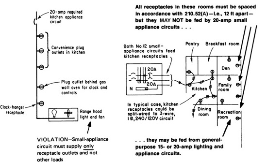
Fig. 210-42. A summary of Sec. 210-52(B)(2) and its two Exceptions. A clock-hanger receptacle and/or a receptacle for the supply of auxiliary equipment on a gas-fired range, oven, or cooktop may also be supplied from the two, or more, small appliance branch circuits.
In part (C)(1) the NEC puts forth the spacing requirements for receptacle outlets installed at counter spaces along the wall. Basically stated, each wall counter space that is 12 in. (300 mm) or wider must have at least one receptacle outlet to supply cord- and plug-connected loads. The receptacles must be placed so that no point along the wall line is more than 24 in. (600 mm) from an outlet. That translates into one outlet every 4 ft. It should be noted that the term “measured horizontally” is intended to recognize application, as shown in Fig. 210-43. The wording is supposed to indicate that there is no need to measure “around the corner” in that case. But, watch out! Some inspectors believe that such application is in violation. In doing so, they are applying the same logic that measures the dimensions of two walls meeting at a corner per 210.52(A)(1) in this manner, and the wording of the two provisions is parallel (“along the floor line” and “along the wall line”). Check with your local electrical inspector to verify acceptability. In spite of numerous attempts to get this language clarified, the Code-making panel has yet to do so.
Fig. 210-43. The term “measured horizontally” can essentially be translated as “when you are facing the counter.” There is no need to measure around the corner here because that would effectively measure the area twice. If the stove were not there and the counter continued around the corner, as in the case of a peninsula counter, the measurement should be continued from the “connecting edge,” which here would be the imaginary line where the stove meets the wall counter.
The exception to 210.52(C)(1) eliminates the need for receptacles where the countertop wall space is behind a range or sink. Where the dimensions are equal to or less than those shown in Fig. 210-44, a receptacle outlet is not required. Note, however, that for the majority of corner applications where the sink or range is on the diagonal, the distance to the corner will exceed 450 mm (18 in.) and qualify for a receptacle in that space. The 450 mm (18-in.) dimension is the altitude of an isosceles triangle whose base is 900 mm (36 in.) and many sinks or ranges will at least equal that width. If this is the case, great care and foresight may be required to avoid major construction problems. Such locations often involve window placements or other difficulties that must be carefully anticipated. Further, the decision to count such spaces in the placement rules is appropriate. The space behind such a sink, for example, works well for a number of appliances, including electric teakettles, that must be routinely refilled with water.
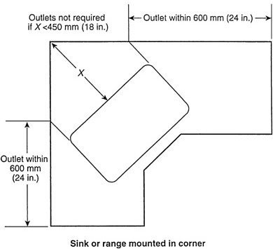
Fig. 210-44. This diagram—Fig. 210.52 in the NEC—provides guidance for countertop receptacles located behind sinks and range tops.
As given in subpart (C)(2) and (C)(3), each freestanding (island) countertop that measures 24 in. (600 mm) or more by 12 in. (300 mm) or more must be provided with one receptacle outlet. The same dimensions apply to peninsular counter-tops, which is a countertop that extends from another counter or a wall. The dimensions are to be measured from “the connecting edge,” which is an imaginary line at the end of the peninsula where it attaches to the other counter (Fig. 210-45). If the area to the right of the so-called connecting edge in Fig. 210-45 measures 24 in. (600 mm) (or more) by 12 in. (300 mm) (or more), at least one receptacle outlet must be provided. In no case is more than one receptacle outlet required at either an island or peninsula counter space, although more may be desirable. If additional receptacles are provided, they must be supplied from one of the 20-A small appliance branch circuits. And, whether the outlet is required or desired, it must be installed as indicated by the last subpart of this section.
Fig. 210-45. As covered in the last sentence of part (C)(3), the area to be considered as “peninsula” counter begins at the imaginary line as shown. If that area has a long dimension of 24 in. (600 mm), or more, by 12 in. (300 mm), or more, at least one receptacle outlet is required to serve that counter space in kitchens and dining rooms at dwellings.
Note that the terminology “long dimension” may have a literal meaning that differs from its intended meaning. In Fig. 210-45, the long dimension is clearly the dimension that is at right angles to the wall counter. Suppose, however, the peninsula was built from standard kitchen countertop stock (625 mm or 25 in.) and extended out from the “connecting edge” only 375 mm (15 in.). Now the literal “long dimension” is 625 mm (25 in.) and runs parallel to the wall and to the connecting edge, and the space qualifies for receptacle coverage because the “short dimension” is 300 mm (12 in.) or greater. One way to approach this is to interpret the connecting edge in this case as extending from the wall at right angles to the wall, instead of parallel to the wall, as shown in Fig. 210-45. If the wall counter is also 625 mm (25 in.) deep, the result of this interpretation is to define this peninsula as being 625 mm + 375 mm = 1.0 m (25 in. + 15 in. = 40 in.) long and 625 mm (25 in.) deep. Such a peninsula also has a mandated receptacle placement, but the receptacle shown on the wall in the drawing would qualify as the peninsula receptacle, avoiding construction difficulties.
Island and peninsula receptacles often involve significant construction issues. Not all peninsulas have base cabinets underneath them. Many are in effect a permanently attached kitchen table, with not much more than a table leg to support the open end and bar stools arranged around the three open sides. Electrical contractors have been forced to literally glue a length of surface metal raceway and box to their underside in order to comply with these rules. If a range or sink creates two peninsulas out of one (see prior discussion), it is very likely that at least one of the two peninsulas or islands resulting from the partition will present construction difficulties. The interpretation offered here is a way to address some of those issues in a sensible way, but the local inspection authority must be consulted because the code language does not address this problem.
The NEC does not cover, with any clarity, another related problem, namely, how long can a peninsula or island get before more than one receptacle is required. There is an answer to this, but it also involves interpretation, in this case as to whether 210.52(C) supersedes 210.52(A), or merely augments 210.52(A) and both rules continue to apply. The plethora of receptacles required on a wall-mounted counter clearly meets the required 210.52(A) placements many times over, but what about peninsulas and islands?
A kitchen island or peninsula clearly and permanently divides the room, and as we have seen, a fixed room divider in the form of “a free-standing bar-type counter” invokes conventional placement requirements, as per 210.52(A)(2)(3). On this basis, it is not unreasonable to require an additional receptacle on an island or peninsula that is over 1.8 m (6 ft long). And, in conjunction with the interpretation offered as to how to place the connecting edge of a peninsula and thereby measure its length, that would be the cut point on how far out a peninsula could extend (or an island could be long) before an additional receptacle would be required. However, here again, the code language does not conclusively address any of these recurring issues, and the local inspectional authority must be consulted. Since the answers to these questions can have a major impact on the cost and design of what amounts to permanently installed furniture, the wise installer is the one who raises the questions as soon as the plans come out with the owner, the inspector, and the kitchen contractor. As always, communication is essential.
Subpart (C)(4) covers the longtime rule regarding pieces of countertops that are separated by cooktops, sinks, and so forth. As indicated, each such piece must be treated as an individual counter. And, if the dimensions are as described in parts (C)(1), (C)(2), or (C)(3), as applicable, of this section, at least one receptacle outlet must be provided.
The requirements given in 210.52(C)(5) mandate where the required receptacle outlets may be installed. That is, a given receptacle outlet may not be counted as one of the required outlets unless it is installed on top of, but not more than 500 mm (20 in.) above, the counter it is intended to serve, and note that no receptacle may be installed face-up in a countertop per 406.4(E). That is a “make sense” proposition inasmuch as a receptacle installed face-up would eventually become a “drain” for soup, milk, water, or whatever else is eventually spilled on the counter. Only the so-called tombstone or doghouse enclosures would be acceptable for surface mounting. Although not entirely clear, it is assumed that the 20 in. must be measured from the counter surface, not the top of the backsplash. In addition, and in correlation with 210.52(3), a receptacle mounted inside an appliance garage, or otherwise not readily accessible due to the placement of a sink, range top, or other appliance fastened in place, does not qualify as providing the required countertop coverage.
Note that the basic rule generally requires the outlet to be mounted above, or on top of, the counter. The basic rule does not recognize installation of an outlet below the counter space. However, where the counter does not extend more than 6 in. (150 mm) beyond “its support base,” the exception to 210.52(C)(5) permits installation of a receptacle outlet below, but not more than 300 mm (12 in.) below the counter. And where the outer edge of the countertop does extend more than 6 in. beyond its support base, any “below-the-countertop” receptacles must be installed so that the receptacle, itself, is not more than 6 in. from the outer edge. That would necessitate the use of either a surface-mounted receptacle or plug-mold type of receptacle to ensure that when measuring from the face of the receptacle or edge of the plug mold, the distance to the outer edge of the countertop overhang is not more than 6 in.
Note that the allowance for a receptacle mounted below the countertop only applies to island and peninsular counters, and even on those counters the exception will not apply unless the counter is flat. If there are two levels to the counter for any reason, then the receptacle has to be placed in the vertical rise between the two levels. Further, if there are suspended upper cabinets over the island or peninsula such that a receptacle could be mounted so as to be not more than 500 mm (20 in.) above the counter, then that opportunity must be used, and a placement on the side of a base cabinet is not allowed.
The NEC is trying to minimize instances where the exception will be used in order to lessen the opportunities for toddlers to pull over dangerous appliances that could severely injure them by spilling hot liquid on their heads or otherwise. On the other hand, the NEC also recognizes that a flat island or peninsula is like someone’s kitchen table, and a mandatory tombstone outlet is a nonstarter in the mind of the public. The result is a reasonable compromise that minimizes the instances of base-mounted receptacles; ultimately the parents are responsible for policing how they connect kitchen appliances when toddlers are in the house. The other exception allows receptacles below a counter, whether for an island or otherwise, in construction for the physically disabled. The usual procedure here is to mount surface metal raceway with receptacles under the counter lip where someone in a wheel chair can reach it easily (Fig. 210-46).
Fig. 210-46. This section indicates where required outlets intended to serve counter space in dwellings must be installed. Remember that below-the-counter mounting is only permitted on a flat island or peninsula, and where the overhang does not exceed 150 mm (6 in.).
Part (D) requires the installation of at least one receptacle outlet adjacent to and within 3 ft of each washbasin location in bathrooms of dwelling units—and 210.60 requires the same receptacle in bathrooms of hotel and motel guest rooms and suites. This receptacle may be mounted in an adjacent wall, or partition, or within the side or face of the vanity not more than 12 in. below the vanity’s countertop. The Code requires a dedicated circuit for bathroom receptacles installed in dwellings. In every bathroom, at least one receptacle outlet must be installed at each basin and any such outlet(s) must be supplied from the dedicated 20-A branch circuit (Fig. 210-47), as required by 210.11(C)(3). If a bathroom has two basins, two receptacles will usually be required unless the basins are small and very close together, or unless a receptacle is mounted between the basins, perhaps horizontally in a backsplash. And yes, receptacle outlets have been successfully installed in, yes in, bathroom mirrors, but a receptacle on each side is usually more cost effective.
Fig. 210-47. A dedicated 20-A branch circuit must be provided to supply required receptacle outlets installed “adjacent” to bathroom sinks, as well as any other receptacle outlets installed in the bathroom. The outlet installed below the counter space here is now clearly acceptable, provided it is not more than 300 mm (12 in.) below the basin countertop.
Part (E) requires that at least one outdoor receptacle “accessible at grade level and not more than 6 ft 6 in. (2.0 m) above grade” must be installed “while standing at grade level” at the front and back for every one-family house (“a one-family dwelling”) and grade-level accessible unit in a two-family dwelling. This has the almost unbelievable effect of disallowing any receptacle placed on an open deck, even a deck a foot above grade with no railing and the receptacle readily accessible from grade, from counting as the required outside receptacle, unless that receptacle is so close to the edge of the deck that it can be reached without needing to step on to the deck. And note that there will be a receptacle outlet on that deck. Why? Because in another 2008 change the NEC now requires that every deck, balcony, and porch that is accessible from within any dwelling unit (whether one, two, or multifamily construction) have a receptacle outlet for the outdoor space, located not over 2.0 m (6½ ft) above the floor. There is an exception only for very small areas not larger than 1.86 m2 (20 ft2).
Part (E) also requires that townhouse-type multifamily dwellings be provided with at least one GFCI-protected outdoor receptacle outlet not over 2.0 m (6½ ft) above grade. The front-and-back provision and the while-standing-on-grade provision do not apply to multifamily construction, but the outdoor porch, deck, and balcony provisions do apply. Thus, for multifamily housing only one outdoor receptacle is required, and located at either the front or the back, and anywhere accessible from grade, such as up some porch steps. The distinction between multifamily housing and single- or two-family construction is not obvious because it relies on construction details that must be reviewed, preferably with the local building official. Specifically it must be determined whether the separations between occupancies are fire separation walls of specified hourly ratings, or true fire walls that are made of masonry or concrete, run from grade to roof line or above, and that will survive a conflagration on one side.
Fire walls define buildings per Art. 100, so much depends on this evaluation. Due to their expense, most fire separations are not fire walls but rather other fire-resistant construction that has enough of an hourly rating to allow the occupants to escape in an orderly way, as defined by the local building code. In some cases a building will have both for other reasons. For example, there are many examples of structures with eight dwelling units as depicted in Fig. 210-48 that have a fire wall down the middle, creating two four-family dwellings. This has been done to at various times to avoid expensive fire alarm systems and sprinklers that would otherwise have been required at the time if the structure had qualified as a single building. Most electrical inspectors will defer to the judgment of the local building official as to how the local building code classifies the nature of an occupancy separation.
Part (F) requires that at least one receptacle—single or duplex or triplex—must be installed for the laundry of a dwelling unit. Such a receptacle and any other receptacles for special appliances must be placed within 6 ft (1.8 m) of the intended location of the appliance. Exceptions apply for multifamily housing where central laundry facilities are provided on site for the occupants, or in other than one-family dwellings in instances where on-site laundry facilities are not to be installed. And part (G) requires a receptacle outlet in a basement in addition to any receptacle outlet(s) that may be provided as the required receptacle(s) to serve a laundry area or other designated equipment such as a whole-house vacuum system in the basement. One receptacle in the basement at the laundry area located there may not serve as both the required “laundry” receptacle and the required “basement” receptacle. A separate receptacle has to be provided for each requirement to satisfy the Code rules.
210.52(G) requires that at least one receptacle outlet be provided in each portion of the basement that is “unfinished” in a one-family house, in addition to any required for a basement laundry or other dedicated use (Fig. 210-49).
Fig. 210-48. Front and rear-receptacle outlets are required outdoors for town-house-type structures as shown, but only if true fire walls divide the structure into multiple single- or two-family dwellings. With mere fire separation walls and not true fire walls, this is multifamily housing and only one outdoor receptacle per unit is required. [Sec. 210.52(E).]
Fig. 210-49. Only one basement receptacle is required (in addition to any for the laundry), but all general-purpose receptacles in unfinished basements must be GFCI protected. [Sec. 210.52(G).]
In other words, if a finished section of a basement results in two noncontiguous unfinished sections in different parts of a basement, then both of those unfinished sections must have a receptacle installed on a general purpose branch circuit. It calls for at least one receptacle in an attached garage of a one-family house. But for a detached garage of a one-family house, the rule simply requires that one receptacle outlet must be installed in the detached garage if—for some reason other than the NEC—electric power is run to the garage, such as where the owner might desire it or some local code might require it (Fig. 210-50). The rule itself does not require that electric power be run to a detached garage to supply a receptacle there.
Fig. 210-50. Detached garage may be required to have a receptacle and lighting outlet. [Sec. 210.52(G).]
Therefore, if the required “basement” receptacle is installed in an “unfinished” basement—that is, a basement that has not been converted to, or constructed as, a recreation room, bedroom, or den—such a receptacle would be required to be provided with GFCI protection [210.8(A)(5)]. And, that same rule requires that any additional receptacles in an unfinished basement be GFCI-protected. In addition, all receptacles installed in a dwelling-unit garage (attached or detached) must have GFCI protection, as required by 210.8(A)(2). Figure 210-51 shows required receptacles per 210.52 (E), (F), and (G) for a one-family dwelling.
In part (H), a receptacle outlet is required in any dwelling-unit hallway that is 10 ft (3.0 m) or more in length. This provides for connection of plug-in appliances that are commonly used in halls—lamps, vacuum cleaners, and so forth. The length of a hall is measured along its centerline. Although 210.52(H) calls for one receptacle outlet for each dwelling-unit hallway that is 10 ft (3.0 m) or more in length, part (H) does not specify location or require more than a single receptacle outlet. However, good design practice would dictate that a convenience receptacle should be provided for each 10 ft (3.0 m) of hall length. And they should be located as close as possible to the middle of the hall. Note that the rule applies within dwelling units only, and therefore does not apply to a common hallway of a multifamily building or a hotel, although it would be obviously good design to provide receptacles in those other buildings.
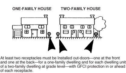
Fig. 210-51. These specific receptacles are required for dwelling occupancies. [Sec. 210.52(E), (F), and (G).]
210.60. Guest Rooms or Guest Suites, Dormitories, and Similar Occupancies. The number of receptacles in a guest room of a hotel or motel, or an equivalent sleeping room of a dormitory or similar location, must be determined by the every-12-ft rule of 210.52(A) but may be located where convenient for the furniture layout. In other words, first lay out the room on paper as though 210.52(A) applied as written, and count the receptacles that result. Then, shift the receptacles if desired to accommodate a permanent furniture arrangements, but do not decrease the total number. In addition, make sure that no fewer than two of the receptacle outlets are readily accessible. If a receptacle outlet falls behind the bed, install some means of assuring that when the bed is moved against the wall, any cords plugged into the receptacle are not damaged (a wet-location “in-use” cover might suffice), or locate the receptacle low enough so as to be out of the way. Where “permanent provisions for cooking” are installed in guest rooms or suites, the installation must satisfy the rule of 210.18 and be wired just as if it were an individual dwelling unit within a multifamily dwelling.
210.62. Show Windows. The rule here calls for one receptacle in a show window for each 3.7 m (12 ft), or major fraction thereof, of length (measured horizontally) to accommodate portable window signs and other electrified displays (Fig. 210-52). The receptacles must be installed within 450 mm (18 in.) of the top of the window to count.
Fig. 210-52. Receptacles are required for show windows in stores or other buildings. (Sec. 210.62.)
210.63. Heating, Air-Conditioning, and Refrigeration Equipment Outlet. A general-purpose 125-V receptacle outlet must be installed within 25 ft (7.5 m) of heating, air-conditioning, and refrigeration equipment. Although the 1999 NEC limited application of this rule to equipment located on rooftops and in attics and crawl spaces (Fig. 210-53), the maintenance receptacle required by this rule must be provided wherever the equipment is installed, and now the rule applies wherever the equipment is located. The receptacles must be on the same level as the equipment, which is occasionally an issue on discontinuous rooftops where a “nearby” receptacle within 7.5 m (25 ft) as the crow flies in actuality requires a ladder to reach. Common sense would dictate that an additional receptacle need not be installed where there is another properly rated receptacle within 25 ft and on the same level as the equipment. For example, if
Fig. 210-53. Maintenance receptacle outlet required for rooftop mechanical equipment as well as for such equipment in all other locations—indoors and outdoors. (Sec. 210.63.)
one of the outdoor receptacles installed at a dwelling unit falls within 7.5 m (25 ft) of this equipment, an additional receptacle need not be installed. The service receptacle must not be connected to the load side of the disconnect switch for the equipment for obvious reasons. Note that the rule does not apply to pure ventilating equipment (the “V” in the familiar acronym “HVAC”) and it also does not apply to evaporative coolers (the so-called “swamp coolers”) at single- and two-family dwellings.
210.70. Lighting Outlets Required. The basic rule of part (A)(1) requires at least one wall switch-controlled lighting outlet in habitable rooms and in bathrooms of dwelling units. The rule of part (A)(2) calls for wall-switch-controlled lighting outlets in halls, stairways, attached garages, “detached garages with electric power,” and at outdoor entrances and exits in dwelling units.
The rule of 210.70(A)(1) basically requires that a “wall-switched controlled” lighting outlet be provided in every room that would be required to be provided with a receptacle outlet as defined in 210.52(A). While that requirement constitutes the basic rule, a wall-switch-controlled receptacle will satisfy Exception No. 1 to 210.70(A)(1) where used in every “habitable room” except the kitchen—which, like the bathrooms in dwelling units, must always have a wall-switch-controlled lighting outlet. Other areas of dwelling units are covered in part 210.70(A)(2), while storage and equipment space are governed by part (A)(3).
The word bathrooms is in the basic rule because various building codes do not include bathrooms under their definition of “habitable rooms.” So the word “bathroom” was needed to ensure that the rule covered bathrooms. The rule does not stipulate that the required “lighting outlets” must be ceiling lighting outlets; they also may be wall-mounted lighting outlets (Fig. 210-54).
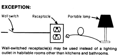
Fig. 210-54. Lighting outlets required in dwelling units. (Sec. 210.70.)
Two exceptions are given to the basic requirements in (A)(1). Exception No. 1 notes that in rooms other than kitchens and bathrooms, a wall-switch-controlled receptacle outlet may be used instead of a wall-switch-controlled lighting outlet. The receptacle outlet can serve to supply a portable lamp, which would give the necessary lighting for the room.
Part (A)(1), Exception No. 2, indicates two conditions under which the use of an occupancy sensor is permitted to control any of the required lighting outlets designated in the basic rule: (1) where used in addition to the required wall switch and (2) where the sensor is equipped with manual override and is mounted at the “customary” switch location. Notice that the literal wording only permits such control for “lighting outlets.” Therefore, even though it is not entirely clear, it must be assumed that occupancy sensor control of a receptacle outlet—installed in accordance with the first exception to this section—is not permitted.
In 210.70(A)(2)(a), the Code calls for wall-switched lighting outlets for all those “other” areas in dwellings. Specifically, hallways and stairways must be provided with at least one wall-switch-controlled lighting outlet.
Part (A)(2)(a) also requires a wall-switch-controlled lighting outlet in every attached garage of a dwelling unit (such as a one-family house). But, for a detached garage of a dwelling unit, a switch-controlled lighting outlet is required only if the garage is provided with electric power—whether the provision of power is done as an optional choice or is required by a local code. Note that the NEC rule here does not itself require running power to the detached garage for the lighting outlet, but simply says that the lighting outlet must be provided if power is run to the garage.
Part (A)(2)(b) requires that outdoor entrances for personnel that afford grade-level access at dwelling unit garages be provided with an exterior lighting outlet. The second sentence clarifies that “a vehicle door in an attached garage is not considered as an outdoor entrance.” This makes it clear that the Code does not require such a light outlet at any garage door that is provided as a vehicle entrance because the lights of the car provide adequate illumination when such a door is being used during darkness. But the wording of this sentence does suggest that a rear or side door that is provided for personnel entry to an attached garage would be “considered as an outdoor entrance” because the note excludes only “vehicle” doors. Such personnel entrances from outdoors to the garage would seem to require a wall-switched lighting outlet.
At least one lighting outlet must be installed in every attic, underfloor space, utility room, and basement if it is used for storage or if it contains equipment requiring servicing. In such cases, the lighting outlet must frequently be controlled by a wall switch, but not always. The rule specifically allows a pull-chain lampholder or luminaire, provided it is reachable (“at least one point of control”) at the usual point of entry. However, for equipment requiring servicing, the lighting outlet must also be located at or near the equipment. If the equipment is at the point of entry, or if there is not such equipment and the space is only used for storage, then the pull chain at the entry will do. However, if there is such equipment and it is remote from the entry, then a wall switch is the only practical method because the luminaire or lampholder will be over at the equipment.
Part (A)(2)(c) requires that stairways between levels that have six or more risers have wall switch control from both ends of the stairway, with additional control required if the stairway includes a landing with an “entryway” between floor levels, as is common with split-level houses. The “entryway” provision closes a loophole in the top-and-bottom rule that would otherwise have no wall switch control over the stairway lighting available to an occupant returning through the front door. Note that this rule applies even to a stairway connecting to an unfinished attic, and therefore a three-way switch loop or some other control must be arranged at both ends of the attic stair in this case.
Where using any occupancy sensor for control of lighting, the use of a sensor that fails in the “on” position would be preferable to one that fails “off” or one that fails “as is.” Such a fail-safe feature on any sensor is not required but is preferable because control of the lighting outlet can be provided from the conventional wall switch or manual override until such time as the sensor can be replaced (Fig. 210-55). But, in the Exception to (A)(2)(a, b, and c), the Code states that “in hallways, stairways, and at outdoor entrances remote, central, or automatic control of lighting shall be permitted.” This latter recognition appears to accept remote, central, or automatic control as an alternative to the wall switch control mentioned in the basic rules.
Fig. 210-55. Occupancy sensor control for lighting outlets in dwellings must be as shown here. Either a sensor and a conventional wall switch or a sensor with a manual override installed at the “customary” wall-switch location must be provided. Remember, the rule here only applies to dwellings.
210.70(B) notes that at least one wall-switch-controlled lighting outlet is to be provided for guest rooms in hotels, motels, or similar occupancies. As in the case of conventional dwelling units, exceptions provide for wall switch control of receptacles in other than bathrooms, and in kitchens where provided (Fig. 210-56). In addition the exceptions also allow for occupancy sensors on the same basis as for dwelling units generally.
Part (C) of 210.70 requires that either a lighting outlet containing a switch—such as the familiar pull-chain porcelain lampholder—or a wall-switch-controlled lighting outlet must be provided in attics or underfloor spaces housing heating, A/C, and/or refrigeration equipment—in other than dwelling units. The lighting outlet must be located at or near the equipment to provide effective illumination. And the control wall switch must be installed at the point of entry to the space.
Fig. 210-56. Switch-controlled lighting outlet in kitchen and bathroom. [Sec. 210.70(A).]
215.1. Scope. Feeders are the conductors that carry electric power from the service equipment (or generator switchboard, where power is generated on the premises) to the overcurrent protective devices for branch circuits supplying the various loads. Subfeeders originate at a distribution center other than the service equipment or generator switchboard and supply one or more other distribution panelboards, branch-circuit panelboards, or branch circuits. Code rules on feeders apply also to all subfeeders for the simple reason that all subfeeders meet the definition of a feeder, and for this reason the NEC does not recognize the term (Fig. 215-1). It will not be used subsequently in this book.
As a matter of good design, for the given circuit voltage, feeders and sub-feeders must be capable of carrying the amount of current required by the load, plus any current that may be required in the future. Selection of the size of a feeder depends on the size and nature of the known load computed from branch-circuit data, the anticipated future load requirements, and voltage drop. However, the NEC does not require owners and installers to be wise about the future, and a feeder that will carry the load connected to it as determined by Art. 220 is NEC compliant. Section 90.1(B) clearly states that an NEC-compliant installation will be “essentially free from hazard, but not necessarily efficient, convenient, or adequate for good service or future expansion of electrical use.”
Fig. 215-1. Article 215 applies only to those circuits that conform to the NEC definition of “feeder.” (Sec. 215.1.)
Article 215 deals with the determination of the minimum sizes of feeder conductors necessary for safety. Overloading of conductors may result in insulation breakdowns due to overheating; overheating of switches, busbars, and terminals; the blowing of fuses and consequent overfusing; excessive voltage drop; and excessive copper losses. Thus the overloading will in many cases create a fire risk and is sure to result in very unsatisfactory service.
215.2. Minimum Rating and Size. The actual maximum load on a feeder depends upon the total load connected to the feeder and the demand factor(s) as established by the rules in parts III, IV, and V of Art. 220.
From an engineering viewpoint, there are two steps in the process of predetermining the maximum load that a feeder will be required to carry: first, a reasonable estimate must be made of the probable connected load; and, second, a reasonable value for the demand factor must be assumed. From a survey of a large number of buildings, the average connected loads and demand factors have been ascertained for lighting and small appliance loads in buildings of the more common classes of occupancy, and these data are presented in parts III, IV and V of Art. 220 as minimum requirements. That is, it is not permissible to assume any demand factor that would result in a calculated load that is less than the Code-prescribed minimum. However, given that calculations in accordance with the NEC provide for no future growth or additional loading, providing capacity for less than the Code-prescribed minimum represents poor design and is a violation of the NEC.
The load is specified in terms of voltamperes per square foot for certain occupancies. These loads are here referred to as standard loads, because they are minimum standards established by the Code in order to ensure that the service, feeder, and branch-circuit conductors will have sufficient carrying capacity for safety.
The key to accurate determination of required feeder conductor capacity in amperes is effective calculation of the total load to be supplied by the feeder. Feeders and subfeeders are sized to provide sufficient power to the circuits they supply. For the given circuit voltage, they must be capable of carrying the amount of current required by the load, plus any current which may be required in the future. The size of a feeder depends upon known load, future load, and voltage drop.
The minimum load capacity which must be provided in any feeder or sub-feeder can be determined by considering NE Code requirements on feeder load. As presented in Sec. 215.2, these rules establish the minimum load capacity to be provided for all types of loads.
The first sentence of 215.2 requires feeder conductors to have ampacity at least equal to the sum of loads on the feeder, as determined in accordance with Art. 220. And 215.3 gives rules on the rating of any feeder protective device.
If an overcurrent protective device for feeder conductors is not UL-listed for continuous operation at 100 percent of its rating, the load on the device must not exceed the noncontinuous load plus 125 percent of the continuous load. 215.3 applies to feeder overcurrent devices—circuit breakers and fuses in switch assemblies—and requires that the rating of any such protective device must generally never be less than the amount of noncontinuous load of the circuit (that amount of current that will not be flowing for 3 h or longer) plus 125 percent of the amount of load current that will be continuous (flowing steadily for 3 h or longer) (Fig. 215-2).
For any given load to be supplied by a feeder, after the minimum rating of the overcurrent device is determined from the preceding calculation (noncontinuous plus 125 percent of continuous), then a suitable size of feeder conductor must be selected. For each ungrounded leg of the feeder (the so-called phase legs of the circuit), the conductor must have a table ampacity in the 75°C column that is at least equal to the amount of noncontinuous current plus the amount of continuous current, from the NEC tables of ampacity (Tables 310.16 through 310.21).
Although the rules of 210.19 and 215.2 are aimed at limiting the load on the circuit protective device, the conductor’s ampacity also must be based on the nature of the load. Just as is required for the overcurrent device, the conductor’s ampacity must not be less than the noncontinuous load plus 125 percent of the continuous load, except where derating—either for number of conductors, 310.15(B)(2), or elevated ambient temperature, which must be derated by the factor shown in the Ambient Temperature Correction Factors at the bottom of Tables 310.16 through 310.19—is needed. In those cases, the conductor’s table ampacity in the 75°C column must be not less than the sum of noncontinuous plus 125 percent of the continuous load before any derating is applied. And, after derating is applied, the conductor’s ampacity must be such that the over-current device protects the conductor as required or permitted by 240.4.
Note that the conductor size increase previously described applies only to the ungrounded or phase conductors because they are the ones that must be properly protected by the rating of the protective device. A neutral or grounded conductor of a feeder does not have to be increased; its size must simply have ampacity sufficient for the neutral load as determined from 220.61.

Fig. 215-2. Feeders must generally be loaded to no more than 80 percent for a continuous load. [Sec. 215.2(A)(1).]
The Exceptions for 215.2(A) and 215.3 note that a circuit breaker or fused switch that is UL-listed for continuous operation at 100 percent of its rating may be loaded right up to a current equal to the device rating. Feeder ungrounded conductors must be selected to have ampacity equal to the non-continuous load plus the continuous load—without applying the 1.25 multiplier. The neutral conductor is sized in accordance with 220.61, which permits reduction of neutral size for feeders loaded over 200 A that do not supply electric-discharge lighting, data processing equipment, or other “nonlinear loads” that generate high levels of harmonic currents in the neutral.
Fuses for feeder protection The rating of a fuse is taken as 100 percent of rated nameplate current when enclosed by a switch or panel housing. But, because of the heat generated by many fuses, the maximum continuous load permitted on a fused switch is restricted by a number of NEMA, UL, and NE Code rules to 80 percent of the rating of the fuses. Limitation of circuit-load current to no more than 80 percent of the current rating of fuses in equipment is done to protect the switch or other piece of equipment from the heat produced in the fuse element—and also to protect attached circuit wires from excessive heating close to the terminals. The fuse itself can actually carry 100 percent of its current rating continuously without damage to itself, but its heat is conducted into the adjacent wiring and switch components.
NEMA standards require that a fused, enclosed switch be marked, as part of the electrical rating, “Continuous Load Current Not to Exceed 80 Percent of the Rating of Fuses Employed in Other Than Motor Circuits” (Fig. 215-3). That derating compensates for the extra heat produced by continuous operation. Motor circuits are excluded from that rule, but a motor circuit is required by the NE Code to have conductors rated at least 125 percent of the motor full-load current—which, in effect, limits the load current to 80 percent of the conductor ampacity and limits the load on the fuses rated to protect those conductors. But, the UL Electrical Construction Materials Directory does recognize fused bolted-pressure switches and high-pressure butt-contact switches for use at 100 percent of their rating on circuits with available fault currents of 100,000, 150,000, or 200,000 rms symmetrical A—as marked (Fig. 215-4). (See “Fused Power Circuit Devices” in that UL publication.)
Manual and electrically operated switches designed to be used with Class L current-limiting fuses rated 601 to 4000 A, 600 V AC are listed by UL as “Fused Power Circuit Devices.” This category covers bolted-pressure-contact switches and high-pressure, butt-type-contact switches suitable for use as feeder devices
Fig. 215-3. For branch circuit or feeder, fuses in enclosed switch must be limited for continuous duty. [Sec. 215.2(A)(1).]
Fig. 215-4. Some fused switches and CBs may be used at 100 percent rating for continuous load. [Sec. 215.2(A)(1) Exception No. 1.]
or service switches if marked “Suitable for Use As Service Equipment.” Such devices “have been investigated for use at 100 percent of their rating on circuits having available fault currents of 100,000, 150,000, or 200,000 rms symmetrical amperes” as marked.
CB for feeder protection The nominal or theoretical continuous-current rating of a CB generally is taken to be the same as its trip setting—the value of current at which the breaker will open, either instantaneously or after some intentional time delay. But, as described previously for fuses, the real continuous-current rating of a CB—the value of current that it can safely and properly carry for periods of 3 h or more—frequently is reduced to 80 percent of the nameplate value by codes and standards rules.
The UL Electrical Construction Materials Directory contains a clear, simple rule in the instructions under “Circuit Breakers, Molded-Case.” It says:
Unless otherwise marked, circuit breakers should not be loaded to exceed 80 percent of their current rating, where in normal operation the load will continue for three or more hours.
A load that continues for 3 h or more is a continuous load. If a breaker is marked for continuous operation, it may be loaded to 100 percent of its rating and operate continuously.
There are some CBs available for continuous operation at 100 percent of their current rating, but they must be used in the mounting and enclosure arrangements established by UL for 100 percent rating. Molded-case CBs of the 100 percent continuous type are made in ratings from 225 A up. Information on use of 100-percent–rated breakers is given on their nameplates.
Figure 215-5 shows two examples of CB nameplate data for two types of UL-listed 2000-A, molded-case CBs that are specifically tested and listed for continuous operation at 100 percent of their 2000-A rating—but only under the conditions described on the nameplate. These two typical nameplates clearly indicate that ventilation may or may not be required. Because most switchboards have fairly large interior volumes, the “minimum enclosure” dimensions shown on these nameplates (45 by 38 by 20 in.) usually are readily achieved. But, special UL tests must be performed if these dimensions are not met. Where busbar extensions and lugs are connected to the CB within the switchboard, the caution about copper conductors does not apply, and aluminum conductors may be used.

Fig. 215-5. Nameplates from CBs rated for 100 percent continuous loading. [Sec. 215.2(A)(1) Exception No. 1.]
If the ventilation pattern of a switchboard does not meet the ventilation pattern and the required enclosure size specified on the nameplate, the CB must be applied at 80 percent rating. Switchboard manufacturers have UL tests conducted with a CB installed in a specific enclosure, and the enclosure may receive a listing for 100-percent–rated operation even though the ventilation pattern or overall enclosure size may not meet the specifications. In cases where the breaker nameplate specifications are not met by the switchboard, the customer would have to request a letter from the manufacturer certifying that a 100-percent–rated listing has been received. Otherwise, the breaker must be applied at 80 percent.
To realize savings with devices listed by UL at 100 percent of their continuous-current rating, use must be made of a CB manufacturer’s data sheet to determine the types and ampere ratings of breakers available that are 100 percent-rated, along with the frame sizes, approved enclosure sizes, and the ventilation patterns required by UL, if any.
It is essential to check the instructions given in the UL listing to determine if and under what conditions a CB (or a fuse in a switch) is rated for continuous operation at 100 percent of its current rating.
OCPD (overcurrent protective device) rating For the purpose of comparison, let’s consider a feeder supplying an 800-A fluorescent lighting load connected line-to-neutral, assumed to be operating continuously, and supplied from a circuit made up of three sets of parallel conductors, with each set run in a separate raceway (Fig. 215-6).
Fig. 215-6. The decision to use or not use a 100 percent-rated device will affect the size/rating of these circuit components.
Non-100 percent-protected circuit As indicated, the rules of 215.3 call for a non-100 percent-rated OCPD to be rated not less than the sum of noncontinuous load (in this case 0 A) plus 125 percent of the continuous load, or 1000 A (800 A × 1.25), which means a minimum rating of 1000 A (0 A + 1000 A).
100 percent-protected circuit The rating required for a 100 percent-rated breaker to protect this lighting feeder need be no greater than the actual connected lighting load. Therefore, an 800-A, 100 percent-rated breaker would fully satisfy all applicable rules.
Non-100 percent-protected circuit Another disadvantage to using the non-100 percent-rated breaker is the Code-mandated procedure that must be used to establish the minimum acceptable conductor size for such circuits. As previously indicated, the conductors used with the 1000-A non-100 percent-rated breaker to supply the 800-A lighting load must also have additional capacity. And that capacity must be determined by the method prescribed in 215.2(A), which is not easily understood because the procedure is rather convoluted. Basically stated, the conductor size selected must have an ampacity in the 75°C column of Table 310.16 that is equal to, or greater than, the total of noncontinuous load plus 125 percent of the continuous load, before any derating.
That statement assumes the use of 75°C- or 90°C-rated insulation. In reality, this should be no concern because TW insulation is virtually impossible to find at any supply house. And, as a result, 75°C- or 90°C-insulated conductors will generally be used. But, if 60°C-rated insulation is used, then the selected conductor size must have an ampacity value in the 60°C column of Table 310.16 that is rated no less than the noncontinuous load plus 125 percent of the continuous load.
The other caveats to the rule of 215.2(A) are:
Any and all deratings that may be required for either number of conductors [310.15(B)(2)] or elevated ambient (ambient temperature correction factors at the bottom of Table 310.16) must still be applied. The rule in 215.2(A) does not supersede the Code-described method for determining conductor ampacity (310.15). Instead, it is an additional evaluation that must be performed. After verifying that the selected conductor size has a 75°C ampacity in Table 310.16 that is equal to, or greater than, the sum of noncontinuous load plus 125 percent of the continuous load, the other requirements of 310.15 must be satisfied. If no derating is required, then there is nothing more to do. There are a few things to be aware of where derating is required for conductors that are sized to satisfy the rule of 215.2(A).
Where deratings are required, it is permissible that the derated ampacity be less than the sum of noncontinuous load plus 125 percent of the continuous load. But the conductors must always be properly protected by the overcurrent protective device, as required by Sec. 240.4.
If the derated ampacity is not properly protected in accordance with 240.4 by the rating of the overcurrent device selected, then the next larger size of conductor must be evaluated. However, that evaluation can be limited to just the conductor’s ampacity because the concern for satisfying 215.2(A) was addressed when the previously considered smaller conductor was evaluated.
The final point can not be repeated too much. Remember which temperature column in Table 310.16 must be used in satisfying the rule of Sec. 215.2(A). As most are aware, Table 310.16 has three different columns identified as 60°C, 75°C, and 90°C, under which are listed different insulating materials and the corresponding ampacity for each conductor size. Because current directly equates with heat, the higher-temperature-rated insulations are permitted to carry more current. Even though it is permissible to use the 90°C values for derating purposes, it must be remembered that for the requirement given in Sec. 215.2(A)(1) the ampacity value shown in the 75°C column of Table 310.16 must be used! Where 90°C insulation (e.g., THHN) is used, it is still permissible to use the 90°C ampacity for the purposes of derating, as has long been recognized, but such practice is not permitted in selecting the minimum conductor size to supply continuous loads. Do not confuse the two rules.
Every conductor has a middle and two ends. The rules that apply to determining whether a wire will overheat in use involve an entirely separate set of calculations from those that determine how a termination will behave, and whether the wire as connected will have a sufficient heat sink capability so the connected OCPD will function as its manufacturer and UL tested it. At the end of this book, in conjunction with the discussion of Annex D, Example D3(a), we will tie all of these rules together in one place. The procedures that follow here will be consistent with that discussion, but focus on this concrete example of the cost comparison between 100 percent and conventional OCPDs.
For our example, we must first select a conductor that has a 75°C ampacity in Table 310.16 which when multiplied by 3 (the number of conductors that will be paralleled to make up each phase) equals at least 1000 A.
In Table 310.16, we see that at 75°C, three 400-kcmil copper conductors (335 A each, for a total of 1005 A) are adequate to satisfy the rule of 215.2(A)(1). However, because the load is fluorescent lighting, the rule of 310.15(B)(4) would require us to count the neutral conductor as a current-carrying conductor. And 310.15(B)(2)(a) would call for an 80 percent derating of the Table 310.16 ampacity because there are now more than three current-carrying conductors in the raceway. As indicated, if THHN (90°C-rated) insulation is used, then the derating may be applied against the 90°C ampacity for 400-kcmil copper. Multiplying the 90°C ampacity of 400 kcmil (380 A) times 3 gives us 1140 A. But, when that value is derated by 80 percent to satisfy 310.15(B)(2)(a) for more than three current-carrying conductors, we end up with an ampacity of only 912 A. According to the rule of 240.4(C), where the overcurrent protective device is rated at more than 800 A, the conductor’s ampacity may not be less than the rating of the OC device. The conductor’s ampacity must be equal to, or greater than, the rating of the OC device used. Therefore, because the derated ampacity of the 400-kcmil THHN copper conductors is less than 1000 A, it is not properly protected by the 1000-A-rated device. To supply this load, the next larger size of conductor (500 kcmil) must be evaluated—but only for ampacity. That’s because we have already established that the 400-kcmil copper conductor satisfies 215.2(A). And, if the smaller 400-kcmil conductors were adequately sized, then so should the larger 500s.
To determine the ampacity of the THHN-insulated, 500-kcmil copper conductors under these conditions of use, because we’re using THHN conductors, we can apply the 80 percent derating against the 90°C ampacity value for 500-kcmil copper. Multiply the 430-A table value times the number of conductors (3) and derate by 80 percent. Or,
Derated ampacity = (430 A/wire × 3 wires/phase) ×0.80
= 1290 A/phase × 0.80
= 1032 A
Therefore, the minimum size permitted for the phase conductors protected by the non-100 percent-rated device is THHN-insulated 500-kcmil copper.
100 percent-protected circuit As indicated by the Exception to 215.2(A), the overcurrent device and the conductor size need only be adequate for the load to be served. Therefore, just as the CB need only be rated for 800 A, the circuit conductors need only be rated for 800 A. Where a 100 percent-rated OCPD is used, the basic rule in 215.2(A)(1) does not apply. Therefore, all we’re really concerned with is conductor ampacity. That is, we must select a conductor with a table ampacity that when multiplied by 3 (number of conductors per phase) and derated by 80 percent (because there are still more than three current-carrying conductors in each raceway) is still equal to or greater than 800 A.
From Table 310.16, we select a THHN-insulated 350-kcmil copper conductor with a 90°C table ampacity of 350 A. (Remember: The table ampacity shown in the 90°C column may be used in applying deratings to 90°C-insulated conductors.) As before, multiply the table value by 3 and derate by 80 percent, or:
Derated ampacity = (350 A/wire × 3 wires/phase) ×0.80
= 1050 A/phase × 0.80
= 840 A
Therefore, the use of three THHN-insulated 300-kcmil copper conductors per phase would satisfy all rules regarding the minimum acceptable conductor size permitted for circuiting a 100 percent-rated 800-A device supplying this fluorescent lighting load.
Non-100 percent-protected circuit It is worth noting that the rules given in 215.2(A) do not affect the sizing of the neutral. That is, because the neutral conductor does not generally connect to the CB, there is no need to be concerned with the nature of the load (i.e., continuous or a combination of continuous and noncontinuous). Remember, neutral sizing must satisfy the rules of 220.61. And, in that section, there is no requirement for additional capacity in the neutral where the load to be supplied is a continuous load. However, it certainly seems as if common sense should be applied to the sizing of the neutral for the non-100 percent-protected circuit. Furthermore, effective with the 2008 NEC, there is now express language [215.2(A)(1) Exception No. 2] that specifically exempts a feeder neutral from the upsizing rules at terminations, provided it runs from busbar to busbar and does not land on an OCPD.
The 2005 NEC introduced an additional wrinkle in sizing neutrals on these systems. The neutral must have sufficient ampacity to safely carry a line-to-neutral short circuit without damaging itself or blowing open. Therefore, the neutral in this case must have a size that is not smaller than the required size of an equipment grounding conductor for the system, as determined by Table 250.122. As we have seen when we looked at conduit fill for nonmetallic conduit, the required size is 2/0 AWG for this load if a 125 percent OCPD were used (1000 A) and 1/0 if the 100 percent OCPD (800 A) is used. Since the total neutral capacity will be 3 times a 350-kcmil conductor, this will not be a factor in this case. This issue has significance in instances where the overwhelming majority of the load is line-to-line, resulting in calculated neutral sizes that may be very small, to the point of not being able to handle a short circuit.
Note also that although 250.122(F) normally requires equipment grounding conductors in each parallel raceway to qualify independently as fully rated and sized conductors based on the full rating of the OCPD, this special provision in 215.2(A)(1) second paragraph waives this rule and allows the three neutrals to be considered in terms of their collective ampacity as a group. In addition, 310.4(A) sets the minimum size for paralleled conductors at 1/0 AWG, so in installations such as this that sets yet another floor under the minimum sizing on grounded circuit conductors generally. Again, for this installation with three sets of 350-kcmil neutral conductors, compliance with both of these rules is not in doubt. However, because this is a NEC Handbook, the topic must be considered.
100 percent-protected circuit As was just indicated, whether a 100 percent-rated CB or a non-100 percent-rated CB is used, the Code permits the neutral conductor for both circuits to be the same size. For the example at hand, a neutral conductor of 350-kcmil, THHN-insulated copper conductor would be acceptable regardless of the type of CB used.
Raceway size As has long been the rule, the minimum acceptable size of raceway must be based on the amount of space occupied by the circuit conductors. And in no case may the cross-sectional area of the enclosed conductors exceed 40 percent of the raceway’s cross-sectional area where three or more conductors are run within the raceway, as indicated in Chap. 9 of the NEC.
Non-100 percent-protected circuit In accordance with Note 6 to the tables in Chap. 9, where a mix of conductor sizes is to be run, conduit fill must be determined by using the specific dimensions given for conductors and raceway fill in Tables 5 and 5A and Table 4, respectively.
The phase conductors are 500 kcmil and the neutral is 350 kcmil. From Table 5 we take the square-inch area of a 500-kcmil THHN, which is 0.7073 sq in. That value is multiplied by 3, which is the number of phase conductors in each raceway. The product of that multiplication is then added to the Table 5 value given for the 350-kcmil THHN neutral conductor (0.5242 sq in.) as follows:
Total area = (0.7073 sq in. × 3) + 0.5242 sq in.
= 2.1219 sq in. + 0.5242 sq in.
= 2.6461 sq in.
Next, using the data given for the individual raceways in Table 4, we can determine the minimum acceptable size of raceway. Moving down the 40 percent-fill column of each raceway’s table we find the size that is equal to, or greater than, 2.6461 sq in. The minimum size permitted for this combination of conductors in the common metal raceways—rigid metal conduit, intermediate metal conduit, or electrical metallic tubing—is 3 in. in each case.
To determine the minimum size of nonmetallic conduit, add the square-inch area of a No. 2/0 grounding conductor—from Table 5, if insulated, or from Table 8, if bare—to the 2.6461 sq in. total just determined. Then go to Table 4 and find the minimum size raceway that has a square-inch value in the 40 percent-fill column that is equal to, or greater than, the total of this combination.
100 percent-protected circuit As covered in Note 1 to the tables of Chap. 9, where all the conductors are of the same size and have the same insulation, the data given in the tables of App. C are permitted to be used.
For rigid metal conduit, Table C8 shows that the minimum-size pipe permitted to contain four 350-kcmil THHN insulated conductors is metric designator 78 (trade size 3), which may contain five such 350s. However, Table C4 covering IMC permits four 350-kcmil THHN conductors in a single metric designator 63 (trade size 2½) raceway. And Table C1 also recognizes four 350-kcmil THHN conductors in metric designator 63 (trade size 2½) EMT.
Summary The choice we have to supply this 800 A of fluorescent lighting is between:
1. 1000-A CB/500-kcmil phase conductors/metric designator 78 (trade size 3) conduit
2. 800-A CB/350-kcmil phase conductors/metric designator 63 (trade size 2½) conduit (where IMC or EMT are used)
If larger raceway is used, then larger fittings, boxes, and so forth will also be required. If nonmetallic raceway is used, the equipment grounding conductor would be required to be larger in the 1000-A circuit (2/0 versus 1/0). And in either case, the labor costs will rise.
In addition to those economic realities, a check of one manufacturer’s pricing indicates that the 100 percent-rated 800-A CB is actually less expensive than the non-100 percent-rated 1000-A device, primarily because of the jump in frame size. That is, the 1000-A CB has a 1200-A frame size while the 800-A breaker has an 800-A frame. The larger frame sizes are generally more robust. That is, they are designed to be capable of withstanding greater electrical stresses than the smaller frame sizes. As a result the larger frame size will require more material, engineering, production costs, and so forth; therefore, a greater price is charged. There is an immediate savings to be realized simply by selecting the 800-A, 100 percent-rated device.
The final benefit that should be realized is the elimination of the need for equipment ground fault protection (GFPE). Remember Sec. 215.10 would require any feeder disconnect rated 1000 A or more on a 480Y/277 V system to be provided with equipment ground fault protection of the type required at services. Of course, this protection is not required where such equipment protection is provided ahead of the feeder disconnect, as long as that GFP has not been desensitized by a connection between ground and neutral on the line side of the disconnect, such as at the output of a separately derived system (e.g., a transformer). A 2008 NEC revision to 215.10 Exception No. 2 now expressly covers this point, and disallows any GFPE on the line side of a transformer from being considered as protecting any load side feeders.
One last thing to remember is that the Exception to 215.2(A)(1) requires that the conductors used with 100 percent-rated OC devices must have an ampacity at least equal to the sum of continuous and noncontinuous loads. In the preceding example, the conductor size selected satisfies this requirement because of its 840-A ampacity, which includes all required deratings. If the conductor had a final ampacity of, say, 760 A, it would still satisfy the rules of 240.4 because the circuit is not rated over 800 A. But, the Exception to this rule requires a minimum ampacity—as covered in 310.15 and the accompanying tables—that is not less than the total load supplied.
It certainly seems as if 100 percent-rated devices are the way to go in this particular case. Such an approach will allow maximum utilization and will do so at lower cost! (See Fig. 215-7.)
Fig. 215-7. Non-100 percent-rated circuit versus 100 percent-rated circuit.
As shown in Fig. 215-8, the rule of part (A)(2) of this section requires that the ampacity of feeder conductors must be at least equal to that of the service conductors where the total service current is carried by the feeder conductors. In the case shown, No. 4 TW aluminum is taken as equivalent to No. 6 TW copper and has the same ampacity (55 A).
Fig. 215-8. Feeder conductors must not have ampacity less than service conductors. [Sec. 215.2(A)(2).]
In this section, part (A)(3) notes that it is never necessary for feeder conductors at mobile homes or “individual dwelling units” to be larger than the service-entrance conductors (assuming use of the same conductor material and the same insulation). In particular, this is aimed at those cases where the size of service-entrance conductors for a dwelling unit is selected in accordance with the higher-than-normal ampacities permitted by 310.15(B)(6) for services to residential occupancies. If a set of service conductors for an individual dwelling unit are brought in to a single service disconnect (a single fused switch or circuit breaker) and load and the service conductors are sized for the increased ampacity value permitted by 310.15(B)(6), diversity on the load-side feeder conductors gives them the same reduced heat-loading that enables the service conductors to be assigned the higher ampacity. This rule simply extends the permission of 310.15(B)(6) to those feeders and is applicable for any such feeder for a dwelling unit (a one-family house or an apartment in a two-family or multifamily dwelling, such as an apartment house) or for mobile-home feed (Fig. 215-9). See the discussion in 310.15(B)(6).
Fine-print note (FPN) No. 2 at the end of Sec. 215.2 comments on voltage drop in feeders. It should be carefully noted that with extremely few and very specific exceptions the NEC does not establish any mandatory rules on voltage drop for either branch circuits or feeders. The references to 3 and 5 percent voltage drops are purely advisory—that is, recommended maximum values of voltage drop. The Code normally does not consider excessive voltage drop to be unsafe.
The voltage-drop note suggests not more than 3 percent for feeders supplying power, heating, or lighting loads. It also provides for a maximum drop of 5 percent for the conductors between the service-entrance equipment and the connected load. If the feeders have an actual voltage drop of 3 percent, then only 2 percent is left for the branch circuits. If a lower voltage drop is obtained in the feeder, then the branch circuit has more voltage drop available, provided that the total drop does not exceed 5 percent. For any one load, the total voltage drop is made up of the voltage drop in the one or more feeders plus the voltage drop in the branch circuit supplying that load.

Fig. 215-9. Feeder conductors need not be larger than service-entrance conductors when higher ampacity is used. [Sec. 215.2(A)(3).]
Again, however, values stated in the FPN on voltage drop are recommended values and are not intended to be enforced as a requirement.
Voltage drop should always be carefully considered in sizing feeder conductors, and calculations should be made for peak load conditions. For maximum efficiency, the size of feeder conductors should be such that voltage drop up to the branch-circuit panelboards or point of branch-circuit origin is not more than 1 percent for lighting loads or combined lighting, heating, and power loads and not more than 2 percent for power or heating loads. Voltage drop in most cases is a design concern only, and the applicable design specification may impose lower limits of voltage drop. Voltage-drop limitations are shown in Fig. 215-10 for NEC levels and better levels of drop, as follows:
1. For combinations of lighting and power loads on feeders and branch circuits, use the voltage-drop percentages for lighting load (at left in Fig. 215-10).
2. The word feeder here refers to the overall run of conductors carrying power from the source to the point of final branch-circuit distribution, including feeders, subfeeders, sub-subfeeders, and so forth. As previously noted, the prefix “sub” is no longer correct code terminology.
3. The voltage-drop percentages are based on nominal circuit voltage at the source of each voltage level. Indicated limitations should be observed for each voltage level in the distribution system.
Fig. 215-10. Recommended basic limitations on voltage drop. (Sec. 215.2, FPN No. 2.)
There are many cases in which the previously mentioned limits of voltage drop (1 percent for lighting feeders, etc.) should be relaxed in the interests of reducing the prohibitive costs of conductors and conduits required by such low drops. In many installations a 5 percent drop in feeders is not critical or unsafe—such as in apartment houses.
Voltage-drop tables and calculators are available from a good number of electrical equipment manufacturers. Voltage-drop calculations vary according to the actual circuit parameters (e.g., AC or DC, single- or multiphase, power factor, circuit impedance, line reactance, types of enclosures [nonmetallic or metallic], length and size of conductors, and conductor material [copper, copper-clad aluminum, or aluminum]).
Calculations of voltage drop in any set of feeders can be made in accordance with the formulas given in electrical design literature, such as those shown in Fig. 215-11. From this calculation, it can be determined if the conductor size
Fig. 215-11. Calculating voltage drop in feeder circuits. (Sec. 215.2, FPN No. 2.)
initially selected to handle the load will be adequate to maintain voltage drop within given limits. If it is not, the size of the conductors must be increased (or other steps taken where conductor reactance is not negligible) until the voltage drop is within prescribed limits. Many such graphs and tabulated data on voltage drop are available in handbooks and from manufacturers. Figure 215-12 shows an example of excessive voltage drop—over 10 percent in the feeder.
Fig. 215-12. Feeder voltage drop should be checked. (Sec. 215.2, FPN No. 2.)
215.2(B). Feeders Over 600 V. This part of the section covers medium voltage feeders, for which the ampacity rules are far different. The basic rule is that the ampacity of a medium voltage feeder supplying transformers must match the sum of the primary ratings of the transformers supplied. If such a feeder also supplies utilization equipment, then the minimum ampacity is the sum of any transformer primaries supplied plus the utilization load taken at 125 percent of its maximum design loading based on the maximum current that would be drawn at any one time, thereby allowing for noncoincident loads. If, however, a facility has engineering staff with documented training and experience working with medium voltage power systems, and they exercise supervision over the monitoring, maintenance, and service required for the system, then the engineering staff may alter the sizing of the feeder conductors that are to be installed.
215.4. Feeders with Common Neutral. A frequently discussed Code requirement is that of 215.4, covering the use of a common neutral with more than one set of feeders. This section says that a common neutral feeder may be used for two or three sets of 3-wire feeders or two sets of 4-wire feeders. It further requires that all conductors of feeder circuits employing a common neutral feeder must be within the same enclosure when the enclosure or raceway containing them is metal.
Fig. 215-13. Example of three feeder circuits using a single, “common neutral”—with neutral size reduced as permitted. (Sec. 215.4.)
A common neutral is a single neutral conductor used as the neutral for more than one set of feeder conductors. It must have current-carrying capacity equal to the sum of the neutral conductor capacities if an individual neutral conductor were used with each feeder set. Figure 215-13 shows a typical example of a common neutral, used for three-feeder circuits. A common neutral may be used only with feeders. It may never be used with branch circuits. A single neutral of a multiwire branch circuit is not a “common neutral.” It is the neutral of only a single circuit, even though the circuit may consist of 3 or 4 wires. A feeder common neutral is used with more than one feeder circuit.
215.5. Diagrams of Feeders. This is the code section that authorizes the inspection community to request, and to insist on if necessary, feeder diagrams and load calculations, stipulations of demand factors applied, and recitations of wire sizes and insulation types, etc.
215.7. Ungrounded Conductors Tapped from Grounded Systems. Refer to 210.19 for a discussion that applies as well to feeder circuits as to branch circuits.
215.9. Ground-Fault Circuit-Interrupter Protection for Personnel. A ground-fault circuit interrupter may be located in the feeder and protect all branch circuits connected to that feeder. In such cases, the provisions of 210.8 and Art. 590 on temporary wiring will be satisfied and additional downstream ground-fault protection on the individual branch circuits would not be required. It should be mentioned, however, that downstream ground-fault protection is more desirable than ground-fault protection in the feeder because less equipment will be deenergized when the ground-fault circuit interrupter opens the supply in response to a line-to-ground fault.
As shown in Fig. 215-14, if a ground-fault protector is installed in the feeder to a panel for branch circuits to outdoor residential receptacles, this protector will satisfy the NEC as the ground-fault protection required by 210.8 for such outdoor receptacles.
Fig. 215-14. GFCI in feeder does satisfy as protection for branch circuits. (Sec. 215.9.)
215.10. Ground-Fault Protection of Equipment. This section mandates equipment ground-fault protection for every feeder disconnect switch or circuit used on a 480Y/277-V, 3-phase, 4-wire feeder where the disconnect is rated 1000 A or more, as shown in Fig. 215-15. This is a very significant Code requirement for ground-fault protection of the same type that has long been required by 230.95 for every service disconnect rated 1000 A or more on a 480Y/277-V service.
As indicated by Exception No. 1, GFPE of equipment may be omitted for “continuous industrial” processes, but only if “additional” or “increased” hazards will result where a process is shut down in a nonorderly manner. An example of this principle at work is 695.6(H), which forbids the application of GFPE to a fire pump circuit. Since Chap. 6 provisions automatically vary the requirements of Chap. 1 through 4 per 90.3, the former Exception No. 2 in this location that excluded fire pump disconnects from the need for equipment GFPE has been deleted as unnecessary.
Fig. 215-15. A 480Y/277-V feeder disconnect rated 1000 A or more must have ground-fault protection (GFP) if there is not GFP on its supply side. (Sec. 215.10.)
Exception No. 2 notes that feeder ground-fault protection is not required on a feeder disconnect if equipment ground-fault protection is provided on the supply (line) side of the feeder disconnect and, as noted previously, this exception does not apply when a transformer is interposed between the GFPE and the large feeder to be protected.
The substantiation submitted as the basis for the addition of this new rule stated as follows:
Substantiation: The need for ground-fault equipment protection for 1000 amp or larger 277/480 grounded system is recognized and required when the service equipment is 277/480 volts. This proposal will require the same needed protection when the service equipment is not 277/480 volts. Past proposals attempted to require these feeders be treated as services in order to achieve this protection, but treating a feeder like a service created many other concerns. This proposal only addresses the feeder equipment ground-fault protection needs when it is not provided in the service equipment.
As noted, this rule calls for this type of feeder ground-fault protection when ground-fault protection is not provided on the supply side of the feeder disconnect, such as where a building has a high-voltage service (say, 13,200 V) or has, say, a 208Y/120-V service with a load-side transformer stepping-up the voltage to 480Y/277 V—because a service at either one of these voltages (e.g., 13.2 kV and 208Y/120 V) is not required by 230.95 to have GFP.
215.11. Circuits Derived from Autotransformers. This section recognizes application of autotransformers for supplying a feeder to a panelboard or group of overcurrent devices. This is the same permission given for branch circuits (see 210.9), and with comparable exceptions.
215.12. Identification for Feeders. The rules in parts (A), (B), and (C) of this section present the same requirements for feeder conductors that are given for branch circuits in 210.5. See 210.5 for a discussion of these rules.
220.1. Scope. The revision of this article in the 2005 edition of the Code provides a more logical and coherent approach for establishing the minimum rating of conductors used as branch circuits, feeders, and service conductors. Better arrangement and segregation of rules applying to branch circuits from those that apply to feeders and/or service conductors and vice versa has reduced confusion and made the intent of the Code more understandable. The same Code-making panel (CMP 2) has jurisdiction over Arts. 210, 215, and 220. The article reorganization in 2005 followed an earlier reassignment of provisions among these three articles with the objective that Art. 220 should only address how to calculate a load, whether expressed in amperes of current on a wire or in terms of voltamperes of power required for some portion of an electrical system. For this reason the discussion that follows will only address load calculations. How to translate those results into an appropriate wire selection is a task left to other locations in the NEC and in this book, particularly at the end where Annex D, Example D3(a) is covered. The load calculation examples in Annex D, including D3(a), are also under the jurisdiction of CMP 2, so the examples should correlate with procedures in Art. 220.
The general rules related to calculating branch circuit feeder and service conductors are presented in part I and these sections apply across the board. The rules for calculating the minimum ratings and sizes for branch circuits are given in part II, while those for feeders and service conductors are covered in part III. Part IV covers the alternate methods of calculating feeder loads in certain cases. Part V provides procedures for calculating minimum sizes of feeders and service conductors supplying a farm.
All the calculations and design procedures covered by Art. 220 involve mathematical manipulation of units of voltage, current, resistance, and other measures of electrical conditions or characteristics.
220.5. Calculations. NE Code references to voltages vary considerably. The Code contains references to 120, 125, 115/230, 120/240, and 120/208 V. Standard voltages to be used for the calculations that have to be made to observe the rules of Art. 220 are 120, 120/240, 208Y/120, 240, 480Y/277, 480, 600Y/347, and 600 V. But use of lower voltage values (115, 230, 440, etc.) as denominators in calculations would not be a Code violation because the higher current values that result would ensure Code compliance because of greater capacity in circuit wires and other equipment. Nevertheless, the approach in this book will be to always use the standard values. If a circuit is to be oversized for design reasons, which is often an excellent idea, it is preferable to add the allowance for future growth openly, instead of hiding that decision by using a bogus voltage. Remember that for the majority of loads a decreased voltage results in decreased load current, which is why electric utilities, when faced with demand they cannot cope with, reduce voltage (brownout).
In all electrical systems there is a normal, predictable spread of voltage values over the impedances of the system equipment. It has been common practice to assign these basic levels to each nominal system voltage. The highest value of voltage is that at the service entrance or transformer secondary, such as 480Y/277 V. Then considering a voltage drop due to impedance in the circuit conductors and equipment, a “nominal” mid system voltage designation would be 460Y/265. Variations in “nominal” voltages have come about because of (1) differences in utility-supply voltages throughout the country, (2) varying transformer secondary voltages produced by different and often uncontrolled voltage drops in primary feeders, and (3) preferences of different engineers and other design authorities. Although an uncommon voltage system within the United States, the reference to 600Y/347V is one of many additions that were made to the 1996 NEC that attempt to harmonize the NEC with the Canadian Electrical Code.
Because the NE Code is produced by contributors from all over the nation and of varying technical experiences, it is understandable that diversity of designations would creep in. As with many other things, we just have to live with problems until we solve them.
To standardize calculations, App. D covering the examples at the end of the code book also specifies that nominal voltages of 120, 120/240, 240, and 208/120 V are to be used in computing the ampere load on a conductor. The reason for this is the plain wording of 220.5(A).
In some places, the NE Code adopts 115 V as the basic operating voltage of equipment designed for operation at 110 to 125 V. That is indicated in Tables 430.248 to 430.251. References are made to “rated motor voltages” of 115, 230, 460, 575, and 2300 V—all values over 115 are integral multiples of 115. The last note in Tables 430.249 and 430.250 indicates that motors of those voltage ratings are applicable on systems rated 110 to 120, 220 to 240, 440 to 480, and 550 to 600 V. Although the motors can operate satisfactorily within those ranges, it is better to design circuits to deliver rated voltage. These Code voltage designations for motors are consistent with the trend over recent years for manufacturers to rate equipment for corresponding values of voltage. These voltages are used in the motor rules for historical reasons and nowhere else in the Code.
In this context, the issue of significant figures needs to be addressed. Many calculations involve dividing volt-amperes by volts to get amperes, or something comparable. Usually such a calculation will result in some form of infinitely repeating decimal. Given today’s calculators, work with these machines is simple and potentially misleading due to the illusion of precision.
Load calculations are not an exact science. The inherent nature of large-scale electrical power systems is such that three significant figures is probably more than can actually be relied on as having any meaning whatsoever. The newest example in Annex D, Example D3(a), squarely addresses this issue for the first time, stating “For reasonable precision, volt-ampere calculations are carried to three significant figures only.” The example goes on to state that “Where loads are converted to amperes, the results are rounded to the nearest whole ampere” and due reference is made to 220.5(B).
Rounding to the nearest whole ampere is fully in accordance with these concepts and fully validated statistical procedures. Some numbers go up a little and others go down; there is no real decrease in safety or ultimate results. The majority of tax calculations are now being done as whole dollar calculations for the same reasons. Sec. 220.5(B) specifically authorizes the process for load calculations, with results of 0.5 and up resulting in the number to the left of the decimal increasing by one, and results of less than 0.5 being discarded.
220.12. Lighting Load for Specific Occupancies. Article 220 gives the basic rules on calculation of loads for branch circuits and feeders. The task of calculating a branch-circuit load and then determining the size of circuit conductors required to feed that load is common to all electrical system calculations. Although it may seem to be a simple matter (and it usually is), there are many conditions which make the problem confusing (and sometimes controversial) because of the NE Code rules that must be observed.
Code Table 220.12 lists certain occupancies (types of buildings) for which a minimum general lighting load is specified in voltamperes per square meter (square foot). In each type of building, there must be adequate branch-circuit capacity to handle the total load that is represented by the product of voltamperes per square foot times the square-foot area of the building. For instance, if one floor of an office building is 40,000 sq ft in area, that floor must have a total branch-circuit capacity of 3700 m2 (40,000 ft2) times 39 VA/m2 (3½ VA/ft2) (Code Table 220.12) for general lighting. Note that the total load to be used in calculating required circuit capacity must never be taken at less than the indicated voltamperes per unit area times the area for those occupancies listed. Of course, if the branch-circuit load for lighting is determined from a lighting layout of specific fixtures of known voltampere rating, the load value must meet the previous voltamperes-per-unit area minimum; and if the load from a known lighting layout is greater, then the greater voltampere value must be taken as the required branch-circuit capacity.
Note that the bottom of Table 220.12 requires a minimum general lighting load of 6 VA/m2 (½ VA/ft2) to cover branch-circuit and feeder capacity for halls, corridors, closets, and all stairways. Likewise, an additional 3 VA/m2 (¼ VA/ft2) must be provided for storage areas.
As indicated in 220.12, when the load is determined on a voltamperes-per-unit area basis, open porches, garages, unfinished basements, and unused areas are not counted as part of the area for dwelling unit calculations. Also note that area calculations must be made using the outside dimensions of the “building, apartment, or other area involved.”
When fluorescent or HID lighting is used on branch circuits, the presence of the inductive effect of the ballast or transformer creates a power factor consideration. Determination of the load in such cases must be based on the total of the voltampere rating of the units and not on the wattage of the lamps.
Based on extensive analysis of load densities for general lighting in office buildings, Table 220.12 requires a minimum unit load of only 3½ VA/sq ft—rather than the previous unit value of 5—for “office buildings” and for “banks.”
A footnote at the bottom of the table requires compliance with 220.14(K) for banks and office buildings. That rule establishes the minimum load capacity required for receptacles in such occupancies. The rule in 220.14(K) calls for capacity to be provided based on the larger of the following: 11 VA/m2 (1 VA/ft2) or the actual connected number of receptacles at 1.5 A a piece. In those cases where the actual number of receptacles is not known at the time feeder and branch-circuit capacities are being calculated, it seems that a unit load of 4½ VA/sq ft must be used, and the calculation based on that figure will yield minimum feeder and branch-circuit capacity for both general lighting and all general-purpose receptacles that may later be installed.
Of course, where the actual number of general-purpose receptacles is known, the general lighting load is taken at 3½ VA/sq ft for branch-circuit and feeder capacity, and each strap or yoke containing a single, duplex, or triplex receptacle is taken as a load of 180 VA to get the total required branch-circuit capacity, with the demand factors of Table 220.44 applied to get the minimum required feeder capacity for receptacle loads. Again, where the actual connected known receptacle load is less than 1 VA/sq ft, then a value of 1 VA/sq ft must be added to the total.
220.14. Other Loads—All Occupancies. This section covers rules on providing branch-circuit capacity for loads other than general lighting and designates specific amounts of load that must be allowed for each outlet. This rule establishes the minimum loads that must be allowed in computing the minimum required branch-circuit capacity for general-use receptacles and “outlets not used for general illumination.” 220.14(D) requires that the actual voltampere rating of a recessed lighting fixture be taken as the amount of load that must be included in branch-circuit capacity. This permits local and/or decorative lighting fixtures to be taken at their actual load value rather than having them be taken as “other outlets,” which would require a load allowance of “180 voltamperes per outlet”—even if each such fixture were lamped at, say, 25 W. Or, in the case where a recessed fixture contained a 300-W lamp, allowance of only 180 VA would be inadequate. Note that these loads are not the general lighting loads addressed in 220.12 and included in voltampere per unit area calculations, but rather specialized lighting that may apply in certain applications as described.
Similarly, sign and outline lighting must also be considered separately. Such lighting is not part of the general lighting load and therefore must be accounted for as indicated in the specific sections that cover those types of equipment. In this case Art. 600 has a mandatory minimum circuiting allowance that must be built in to most commercial load calculations. Of course, if the actual load is known to be larger, then the larger number enters the load calculation.
The last sentence of 220.14(I) calls for “each single or each multiple receptacle on one strap” to be taken as a load of “not less than 180 voltamperes”—in commercial, institutional, and industrial occupancies. The rule requires that every general-purpose, single or duplex or triplex convenience receptacle outlet in nonresidential occupancies be taken as a load of 180 VA, and that amount of circuit capacity must be provided for each such outlet (Fig. 220-1). Code intent is that each individual device strap—whether it holds one, two, or three receptacles—is a load of 180 VA. This rule makes clear that branch-circuit and feeder capacity must be provided for receptacles in nonresidential occupancies in accordance with loads calculated at 180 VA per receptacle strap.
Fig. 220-1. Classification of single, duplex, and triplex receptacles. [Sec. 220.14(I).]
If a 15-A, 120-V circuit is used to supply only receptacle outlets, then the maximum number of general-purpose receptacle outlets that may be fed by that circuit is
15 A × 120 V + 180 VA or 10 receptacle outlets
For a 20-A, 115-V circuit, the maximum number of general-purpose receptacle outlets is
20 A × 120 V + 180 VA or 13 receptacle outlets
See Fig. 220-2.
Fig. 220-2. Number of receptacles per circuit, nonresidential occupancy. As shown in the drawing, there is one strap per outlet. Where multiple straps are installed at an outlet, the 180-VA requirement applies per strap. [Sec. 220.14(I).]
Although the Code gives the previously described data on maximum permitted number of receptacle outlets in commercial, industrial, institutional, and other nonresidential installations, there are no such limitations on the number of receptacle outlets on residential branch circuits. There are reasons for this approach.
In 210.52, the Code specifies where and when receptacle outlets are required on branch circuits. Note that there are no specific requirements for receptacle outlets in commercial, industrial, and institutional installations other than for store show windows in 210.62 and equipment for conditioned air and refrigeration in 210.63. There is the general rule that receptacles do have to be installed where flexible cords are used. In nonresidential buildings, if flexible cords are not used, there is no requirement for receptacle outlets. They have to be installed only where they are needed, and the number and spacing of receptacles are completely up to the designer. But because the Code takes the position that receptacles in nonresidential buildings only have to be installed where needed for connection of specific flexible cords and caps, it demands that where such receptacles are installed, each must be taken as a load of 180 VA.
A different approach is used for receptacles in dwelling-type occupancies. The Code simply assumes that cord-connected appliances will always be used in all residential buildings and requires general-purpose receptacle outlets of the number and spacing indicated in 210.52 and 210.60. These rules cover one-family houses, apartments in multifamily houses, guest rooms in hotels and motels, living quarters in dormitories, and so forth. But because so many receptacle outlets are required in such occupancies and because use of plug-connected loads is intermittent and has great diversity of load values and operating cycles, the Code notes at the bottom of Table 220.12 that the loads connected to such receptacles are adequately served by the branch-circuit capacity required by 210.11, and no additional load calculations are required for such outlets.
In dwelling occupancies, it is necessary to first calculate the total “general lighting load” from 220.12 and Table 220.12 (at 33 VA/m2 [3 VA/ft2] for dwellings or 22 VA/m2 [2 VA/ft2] for hotels and motels, including apartment houses without provisions for cooking by tenants) and then provide the minimum required number and rating of 15-A and/or 20-A general-purpose branch circuits to handle that load as covered in 210.11(A). As long as that basic circuit capacity is provided, any number of lighting outlets may be connected to any general-purpose branch circuit, up to the rating of the branch circuit if loads are known. The lighting outlets should be evenly distributed among all the circuits. Although residential lamp wattages cannot be anticipated, the Code method covers fairly heavy loading.
When the preceding Code rules on circuits and outlets for general lighting in dwelling units, guest rooms of hotels and motels, and similar occupancies are satisfied, general-purpose convenience receptacle outlets may be connected on circuits supplying lighting outlets; or receptacles only may be connected on one or more of the required branch circuits; or additional circuits (over and above those required by Code) may be used to supply the receptacles. But no matter how general-purpose receptacle outlets are circuited, any number of general-purpose receptacle outlets may be connected on a residential branch circuit—with or without lighting outlets on the same circuit.
And when small-appliance branch circuits are provided in accordance with the requirements of 210.11(C)(1), any number of small-appliance receptacle outlets may be connected on the 20-A small-appliance circuits—but only receptacle outlets may be connected to these circuits and only in the specified rooms.
210.52(A) applies to spacing of receptacles connected on the 20-A small-appliance circuits, as well as spacing of general-purpose receptacle outlets. That section, therefore, establishes the minimum number of receptacles that must be installed for greater convenience of use.
220.14(H) requires branch-circuit capacity to be calculated for multioutlet assemblies (prewired surface metal raceway with plug outlets spaced along its length). Part (H)(2) says that each 300-mm (1-ft) length of such strip must be taken as a 180-VA load when the strip is used where a number of appliances are likely to be used simultaneously. For instance, in the case of industrial applications on assembly lines involving frequent, simultaneous use of plugged-in tools, the loading of 180 VA/ft must be used. Part (H)(1) allows loading of 180 VA for each 1.5-m (5-ft) section in commercial or institutional applications of multioutlet assemblies when use of plug-in tools or appliances is not heavy. Figure 220-3 shows an example of the more intensive load calculation.
Fig. 220-3. Calculating required branch-circuit capacity for multioutlet assembly. [Sec. 220.14(H).]
Part (G) permits branch-circuit capacity for the outlets required by 210.62 for show windows to be calculated, as shown in Fig. 220-4—instead of using the load-per-outlet value (180 VA) from part (I) of 220.14.
Fig. 220-4. Alternate method for calculating show-window circuit capacity. [Sec. 220.14(G).]
As noted by 220.14(B), 220.54 is permitted to be used in calculating the size of branch-circuit conductors for household clothes dryers; this results in a load of 5000 VA being used for a household electric dryer when the actual dryer rating is not known. This is essentially an exception to 220.14(A), which specifies that the “ampere rating of appliance or load served” shall be taken as the branch-circuit load for an outlet for a specific appliance. A comparable calculation applies to a household cooking appliance; here again the number from Part III if the article on feeders is allowed to be used for a branch circuit. For household ranges, this correlates with 210.21(B)(4) that bases the range receptacle ampere rating on a single range demand load as given in Table 220.55, and that configuration also correlates with the rating of the branch-circuit overcurrent device through 210.20(D).
Part III. Feeder and Service Load Calculations
220.42. General Lighting. For general illumination, a feeder must have capacity to carry the total load of lighting branch circuits determined as part of the lighting design and not less than a minimum branch-circuit load determined on a voltamperes-per-unit-area basis from the table in 220.12.
Demand factor permits sizing of a feeder according to the amount of load which operates simultaneously.
Demand factor is the ratio of the maximum amount of load that will be operating at any one time on a feeder to the total connected load on the feeder under consideration. This factor is frequently less than 1. The sum of the connected loads supplied by a feeder is multiplied by the demand factor to determine the load which the feeder must be sized to serve. This load is termed the maximum demand of the feeder:
Maximum demand load = connected load × demand factor
Tables of demand and diversity factors have been developed from experience with various types of load concentrations and various layouts of feeders and subfeeders supplying such loads. Table 220.42 of the NE Code presents common demand factors for feeders to general lighting loads in various types of buildings (Fig. 220-5).
Fig. 220-5. How demand factors are applied to connected loads. (Sec. 220.42.)
The demand factors given in Table 220.42 may be applied to the total branch-circuit load to get required feeder capacity for lighting (but must not be used in calculating branch-circuit capacity). Note that a feeder may have capacity of less than 100 percent of the total branch-circuit load for only the types of buildings designated in Table 220.42, that is, for dwelling units, hospitals, hotels, motels, and storage warehouses. In all other types of occupancies, it is assumed that all general lighting will be operating at the same time, and each feeder in those occupancies must have capacity (ampacity) for 100 percent of the voltamperes of branch-circuit load of general lighting that the feeder supplies.
example If a warehouse feeder fed a total branch-circuit load of 20,000 VA of general lighting, the minimum capacity in that feeder to supply that load must be equal to 12,500 VA plus 50 percent times (20,000 – 12,500) VA. That works out to be 12,500 plus 0.5 × 7500 or 16,250 VA.
But, the note to Table 220.42 warns against using any value less than 100 percent of branch-circuit load for sizing any feeder that supplies loads that will all be energized at the same time.
220.43. Show-Window and Track Lighting. In providing minimum required capacity in feeders, a load of 150 VA must be allowed for each 2 ft (600 mm) or fraction thereof of lighting track. That amount of load capacity must be provided in feeders and service conductors (see Fig. 220-6) in nonresidential installations and would have to be added in addition to the general lighting load in voltamperes
Fig. 220-6. A single-circuit lighting track must be taken as a load of 150 VA for each 2 ft (610 mm) or fraction thereof, divided among the number of circuits. For a 2-circuit lighting track, each 2-ft (610-mm) length is a 75-VA load for each circuit. For a 3-circuit track, each 2-ft (610-mm) length is a 50 VA load for each circuit (Sec. 220.43.)