Fig. 240-3. Coil-circuit wires of magnetic contactor must be protected as required by 725.23. (Sec. 240.4.)
Fig. 240-4. Protecting a remote-control circuit in accordance with 725.23. (Sec. 240.4.)
current rating of the control conductors. If the branch-circuit overcurrent devices were rated or set at more than 300 percent of the rating of the control conductors, the control conductors would have to be protected by a separate protective device located at the point (B) where the conductor to be protected receives its supply. [See 725.45(C).]
240.4(F) permits the secondary circuit from a transformer to be protected by means of fuses or a CB in the primary circuit to the transformer—if the transformer has no more than a 2-wire primary circuit and a 2-wire secondary circuit. As shown in Fig. 240-5, by using the 2-to-1 primary-to-secondary turns ratio of the transformer, 20-A primary protection will protect against any secondary current in excess of 40 A—thereby protecting, say, secondary No. 8 TW wires rated at 40 A. As the wording of the rule states, the protection on the primary (20 A) must not exceed the value of the secondary conductor ampacity (40 A) multiplied by the secondary-to-primary transformer voltage ratio (120 ÷ 240 = 0.5). Thus, 40 A × 0.5 = 20 A. But it should be carefully noted that the rating of the primary protection must comply with the rules of 450.3(B).
Fig. 240-5. Primary fuses or CB may protect secondary circuit for 2-wire to 2-wire transformer. (Sec. 240.4.)
The rule of part (F) also recognizes protection of the secondary conductors by the primary overcurrent protective device for delta-delta-wound transformers. This permission recognizes that the “per-unit” current value on the secondary side will be equal to or less than the per-unit current value on the primary conductors. And, because a directly proportional current will be carried by both conductors, the overcurrent device on the primary side can protect both sets of conductors, the primary and secondary. For 3- and 4-wire delta-wye-wound transformers, separate overcurrent protection is required for the primary conductors and secondary conductors.
To put this another way, no conductors connected to a dual-voltage transformer secondary can be protected on the primary side by relying on a turns ratio. Consider a 480-V to 120/240-V transformer of the type commonly used to create separately derived single-phase systems for local lighting and receptacles. Suppose the panel on the secondary side is rated 100 A, the secondary conductors are 3 AWG, and the primary-side circuit breaker is rated 50 A. The winding ratio from 480 to 240 V is 2:1, so the maximum current that could flow over the secondary conductors is 100 A, right?
Wrong. If the load in the panel is perfectly balanced, then when the load on the panel exceeds 100 A, the primary side protection will open, true enough. But now suppose the panel load is not balanced. In fact, suppose the worst case happens, and 100 percent of the line-to-neutral load is on only one of the line legs. Now the transformer is, in effect, operating as a 4:1 (480:120 V) transformer. At this point, 100 A of load on the secondary, at 120 V, will cause only 25 A or current to flow in the primary. The transformer will be quite happy, and the primary side protection will be nowhere close to opening. Meanwhile, up to 200 percent of rated current (in this case 200 A) could be drawn on the secondary side before the primary side would open. The so-called protection on the primary side does protect the transformer, but it is absolutely useless in terms of reliably protecting the conductors and other equipment on the secondary side. 725.45(D) clearly makes this point regarding Class 1 control circuit conductors, and 240.21(C)(1) reiterates the point made here in 240.4(F) for power circuits. Figure 240-6 previews the rules in 240.21(C) and Fig. 240-7 gives another example of the problems with potential imbalances on a multi-wire transformer secondary.
Fig. 240-6. Part (C) clearly resolves long-standing controversy. (Sec. 240.4.)
240.5. Protection of Flexible Cords and Fixture Wires. The basic rules of part (A) are that
1. All flexible cords and extension cords must be protected at the ampacity given for each size and type of cord or cable in NEC Tables 400.5(A) and 400.5(B). “Flexible cords” includes “tinsel cord”—No. 27 AWG wires in a cord that is attached directly or by a special plug to a portable appliance rated not over 50 W.
Fig. 240-7. Why primary protection may not do the job for 3-wire or 4-wire secondary 40-A-rated wires. (Sec. 240.4.)
2. All fixture wires must be protected in accordance with their ampacities, as given in Table 402.5.
3. The required protection may be provided by use of supplementary over-current protective devices (usually fuses), instead of having branch-circuit protection rated at the low values involved.
Then the basic rules are modified by the rules in parts (B)(1) and (B)(2) applying to each of the preceding rules:
Part (B)(1) applies only to a flexible cord or a tinsel cord (not an “extension cord”) that is “approved for and used with a specific listed (by UL or other recognized test lab) appliance or luminaire.” Such a cord, under the conditions stated, is not required to be protected at its ampacity from NEC Table 400.5. The 2008 NEC removed the qualifier “portable” as a descriptive term for the light, thereby removing a direct conflict with cord-supplied luminaires that rely on flexible cord dropping out of a canopy because the luminaire is supported with aircraft cable that can be adjusted in the field to change the mounting height. Such luminaires are not portable and they are necessarily connected with flexible cord, but they need not be provided with overcurrent protection.
Note that “extension cords” are not covered by part (B)(1) because they are not “approved for and used with a specific listed appliance.” They are covered in part (B)(3) and (B)(4), depending on whether they are a listed extension cord set or field assembled. If they are listed, then there are no longer any prescriptive rules and they are only limited by the listing requirements. If they are field assembled from listed components, then they are only limited by the rules in 400.5, but only where constructed from 14 AWG and larger cord. If they employ 16 AWG cord they can be connected to up to a 20-A (and no larger) branch circuit, and if they are 18 AWG they revert to the default limits of 7 or 10 A from Table 400.5). Refer to the bottom half of Fig. 240-8. Some cords are now available with 18 AWG cord, but such cords have supplementary overcurrent protection in the form of fuses in their plugs, in deference to these rules and in accordance with the requirements of 240.4(D)(1).

Fig. 240-8. Separate rules cover fixture wires and extension cords. (Sec. 240.5.)
Part (B)(2) gives the conditions under which fixture wire does not have to be protected at the ampacity value given in Table 402.5 for its particular size if the fixture wire is any one of the following:
 No. 18 wire, not over 15 m (50 ft) long, connected to a branch circuit rated not over 20 A
No. 16 wire, not over 30 m (100 ft) long, connected to a branch circuit rated not over 20 A
No. 14 or larger wire, of any length, connected to a branch circuit rated not over 30 A
No. 12 or larger wire, of any length, connected to a branch circuit rated not over 50 A
From those rules, No. 16 or No. 18 fixture wire may be connected on any 20-A branch circuit, provided the “run length” (the length of any one of the wires used in the raceway) is not more than 15 (50 ft)—such as for 450 mm to 1.8 m (1½ to 6-ft) fixture whips [410.117(C)], as illustrated in the top part of Fig. 240-8. But, for remote-control circuits run in a raceway from a magnetic motor starter or contactor to a remote pushbutton station or other pilot-control device, 430.72(B) and 725.43 require that a No. 18 wire be protected at not over 7 A and a No. 16 wire at not over 10 A—where fixture wires are used for remote-control circuit wiring, as permitted by Sec. 725.49(A) and (B).
240.6. Standard Ampere Ratings. This is a listing of the “standard ampere ratings” of fuses and CBs for purposes of Code application. However, an important qualification is made by the second sentence of this section. Although this NEC section designates “STANDARD ampere ratings” for fuses and circuit breakers, UL-listed fuses and circuit breakers of other intermediate ratings are available and may be used if their ratings satisfy Code rules on protection. For instance, 240.6 shows standard rated fuses at 1200 A, then 1600 A. But if a circuit was found to have an ampacity of, say, 1530 A and, because 240.4(C) says such a circuit may not be protected by 1600-A fuses, it is not necessary to drop down to 1200-A fuses (the next lower standard size). This final sentence fully intends to recognize use of 1500-A fuses—which would satisfy the basic rule of 240.4(C) for protection rated over 800 A. (Fig. 240-1.)
The last sentence in part (A) of 240.6 designates specific “additional standard ratings” of fuses at 1, 3, 6, 10, and 601 A. These values apply only to fuses and not to CBs. The 601-A rating gives Code recognition to use of Class L fuses rated less than 700 A. The reasoning of the Code panel was:
An examination of fuse manufacturers’ catalogs will show that 601 amperes is a commonly listed current rating for the Class L nontime-delay fuse. Section [430.52(C)(1) (Exception No. 2d)] also lists this current rating as a break point in application rules.
Without a 601 ampere rating, the smallest standard fuse which can be used in Class L fuse clips is rated 700 amperes. Since the intent of Table 430.152 and 430.52 is to encourage closer short-circuit protection, it seems prudent to encourage availability and use of 601-ampere fuses in combination motor controllers having Class L fuse clips.
Because ratings of inverse time circuit breakers are not related to fuse clip size, a distinction between 600 and 601 amperes in circuit breakers would serve no useful purpose. Hence, inverse-time circuit breaker ratings are listed separately. Such separation also facilitates recognition of other fuse ratings as standard.
The smaller sizes of fuses (1, 3, 6, and 10 A) listed as “standard ratings” provide more effective short-circuit and ground-fault protection for motor circuits—in accordance with 430.52, 430.40, and UL requirements for protecting the overload relays in controllers for very small motors. The Code panel reasoning was as follows:
Fuses rated less than 15 amperes are often required to provide short circuit and ground-fault protection for motor branch circuits in accordance with 430.52.
Tests indicate that fuses rated 1, 3, 6 and 10 amperes can provide the intended protection in motor branch circuits for motors having full load currents less than 3.75 amperes (3.75 × 400% = 15). These ratings are also those most commonly shown on control manufacturers’ overload relay tables. Overload relay elements for very small full load motor currents have such a high resistance that a bolted fault at the controller load terminals produces a short-circuit current of less than 15 amperes, regardless of the available current at the line terminals. An overcurrent protective device rated or set for 15 amperes is unable to offer the short circuit or ground fault protection required by 110.10 in such circuits.
An examination of fuse manufacturers’ catalogs will show that fuses with these ratings are commercially available. Having these ampere ratings established as standard should improve product availability at the user level and result in better overcurrent protection.
Since inverse time circuit breakers are not readily available in the sizes added, it seems appropriate to list them separately.
Listing of those smaller fuse ratings has a significant effect on use of several small motors (fractional and small-integral-horsepower sizes) on a single branch circuit as described under 430.53(B).
240.6(B) states that if a circuit breaker has external means for changing its continuous-current rating (the value of current above which the inverse-time overload—or longtime delay—trip mechanism would be activated), the breaker must be considered to be a protective device of the maximum continuous current (or overload trip rating) for which it might be set. This type of CB adjustment is available on molded-case, insulated-case, and air power circuit breakers. As a result of that rule and 240.4, the circuit conductors connected to the load terminals of such a circuit breaker must be of sufficient ampacity as to be properly protected by the maximum current value to which the adjustable trip might be set. That means that the CB rating must not exceed the ampacity of the circuit conductors, except that where the ampacity of the conductor does not correspond to a standard rating of CB, the next higher standard rating of CB may be used, up to 800 A (Fig. 240-9).
Prior to the 1987 edition, the NEC did not require that a circuit breaker with adjustable or changeable trip rating must have load-circuit conductors of an ampacity at least equal to the highest trip rating at which the breaker might be used. Conductors of an ampacity less than the highest possible trip rating could be used, provided that the actual trip setting being used did protect the conductor in accordance with its ampacity, as required in NEC 240.4. Since the 1990 edition, such application may be made only in accordance with the rule in part (C), which says that an adjustable-trip circuit breaker may be used as a protective device of a rating lower than its maximum setting and used to protect conductors of a corresponding ampacity in accordance with 240.4(B) if the trip-adjustment is
Fig. 240-9. An adjustable-trip circuit breaker that has access to its trip adjustment limited only to qualified persons may be taken to have a rating less than the maximum value to which the continuous rating (the longtime or overload adjustment) might be set. (Sec. 240.6.)
1. Located behind a removable and sealable cover, or
2. Part of a circuit breaker which is itself located behind bolted equipment enclosure doors accessible only to qualified persons, or
3. Part of a circuit breaker that is locked behind doors (such as in a room) accessible only to qualified persons
Although this rule permits use of conductors with ampacity lower than the maximum possible trip setting of a CB under the conditions given, this does not apply to fusible switches, and it is never necessary for a fusible switch to have its connected load-circuit conductors of ampacity equal to the maximum rating of a fuse that might be installed in the switch—provided that the actual rating of the fuse used in the switch does protect the conductor at its ampacity.
240.8. Fuses or Circuit Breakers in Parallel. The basic rule prohibits the use of parallel fuses, which at one time was acceptable when fused switches had ratings above 600 A. However, fused switches and single fuses (such as Class L) are now readily available in sizes up to 6000 A. Moreover, this rule prohibits the use of CBs in parallel unless they are tested and approved as a single unit. At one time, this Code rule did not mention CBs. However, it is acceptable to factory-assemble CBs or fuses in parallel and have them tested and approved as a unit.
The first sentence recognizes fuses or CBs in parallel where “factory assembled” and “listed as a unit.” Such units are used to increase the rating of over-current protection in marine, over-the-road, off-road, commercial, and industrial installations. Use of other than listed units that are manufactured as units is a clear and direct violation.
240.10. Supplementary Overcurrent Protection. Supplementary overcurrent protection is commonly used in lighting fixtures, heating circuits, appliances, or other utilization equipment to provide individual protection for specific components within the equipment itself. Such protection is not branch-circuit protection and the NE Code does not require supplemental overcurrent protective devices to be readily accessible. Typical applications of supplemental over-current protection are fuses installed in fluorescent fixtures and cooking or heating equipment where the devices are sized to provide lower overcurrent protection than that of the branch circuit supplying such equipment. This is discussed under 424.19 and 424.22 on electric space-heating equipment.
Years ago there was no allowance for conventional overcurrent protective devices to be in locations that were not readily accessible, and so they were classified, essentially at the convenience of the engineer, as supplementary. One common example is the combination plug fuse and snap switch assemblies that come premounted in box covers or handy box covers, particularly where mounted in not-readily-accessible locations such as adjacent to ceiling-mounted equipment and/or fractional-horsepower motors. Since the plug fuse is actually rated for branch-circuit protection, this wasn’t really correct until the rule in 240.24(A)(4) caught up with the very long-standing allowance in 404.8(A) Exception No. 2. Now that 240.24(A)(4) allows this openly (although only adjacent to the equipment supplied), the need to artificially classify branch-circuit rated protective devices as supplementary devices has largely gone away.
240.12. Electrical System Coordination. This rule applies to any electrical installation where hazard to personnel would result from disorderly shutdown of electrical equipment under fault conditions. The purpose of this rule is to permit elimination of “overload” protection—that is, protection of conductors at their ampacities—and to eliminate unknown or random relation between operating time of overcurrent devices connected in series.
The section recognizes two requirements, both of which must be fulfilled to perform the task of “orderly shutdown.”
One is selective coordination of the time-current characteristics of the short-circuit protective devices in series from the service to any load—so that, automatically, any fault will actuate only the short-circuit protective device closest to the fault on the line side of the fault, thereby minimizing the extent of electrical outage due to a fault.
The other technique that must also be included if overload protection is eliminated is “overload indication based on monitoring systems or devices.” A note to this section gives brief descriptions of both requirements and establishes only a generalized understanding of “overload indication.” Effective application of this rule depends on careful design and coordination with inspection authorities.
It should be noted, however, that it says that the technique of eliminating overload protection to afford orderly shutdown “shall be permitted”—but does not require such application. Although it could be argued that the wording implies a mandatory rule, consultation with electrical inspection authorities on this matter is advisable because of the safety implications in nonorderly shutdown due to overload. Emergency systems (700.27), legally-required standby systems (701.18), critical operations power systems (708.54) and main elevator feeders, and multiple elevator driving machines on a single feeder (620.62) now require selective coordination within their scope.
240.13. Ground-Fault Protection of Equipment (GFPE). Equipment ground-fault protection—of the type required for 480Y/227-V service disconnects—is now required for each disconnect rated 1000 A or more that serves as a main disconnect for a building or structure. Like 215.10, this section expands the application of protection against destructive arcing burndowns of electrical equipment. The intent is to equip a main building disconnect with GFPE whether the disconnect is technically a service disconnect or a building disconnect on the load side of service equipment located elsewhere. This was specifically devised to cover those cases where a building or structure is supplied by a 480Y/277-V feeder from another building or from outdoor service equipment. Because the main disconnect (or disconnects) for such a building serves essentially the same function as a service disconnect, this requirement makes such disconnects subject to all of the rules of 230.95, covering GFPE for services (Fig. 240-10).
Fig. 240-10. Ground-fault protection is required for the feeder disconnect for each building—either at the building or at the substation secondary. (Sec. 240.13.)
The last part of this section is intended to clarify that the rule applies to the rating of individual disconnects and not to the sum of disconnects. Where an individual disconnect is rated 1000 A, or more, GFPE protection must be provided.
There are three conditions under which GFPE may be omitted. The first condition here excluded from the need for such GFPE disconnects for critical processes where automatic shutdown would introduce additional or different hazards. And as with service GFPE, the requirement does not apply to fire-pump disconnects.
As covered in 240.13(2), the need for GFPE on a building or structure disconnect is suspended if such protection is provided on the upstream (line) side—either service or feeder disconnect GFPE—of the feeder disconnect. The rule (eliminated in the 1996 NEC) used to stipulate that there must not be any desensitizing of the ground-fault protection because of downstream neutral regrounding, that is, bonding to the equipment grounding conductor and grounding electrode conductor in the downstream building disconnect. If this were done, and it is now prohibited in these cases by 250.32(B) Exception, any ground-fault current in the downstream building that develops will pass over the bonding connection and return to the upstream GFPE not as unbalanced and detectable fault current, but rather as perfectly balanced and undetectable neutral load current.
The problem with this was that the rule recognizing the upstream protection was, as it is now, in the form of an exception. The “requirement” to avoid desensitization was added to the exception. However, since it was part of an exception, it was unenforceable. If someone desensitized the upstream GFPE, what rule was broken? True, the exception became inoperable and therefore GFPE was now required at the building disconnect. However, if there were additional downstream cross-connections, then neither GFPE device would work properly. The real solution was to address the problem in the second-building regrounding rules in Art. 250. This was successfully done in the 1999 NEC, eliminating the problem.
240.15. Ungrounded Conductors. A fuse or circuit breaker must be connected in series with each ungrounded circuit conductor—usually at the supply end of the conductor. A current transformer and relay that actuates contacts of a CB is considered to be an overcurrent trip unit, like a fuse or a direct-acting CB (Fig. 240-11).
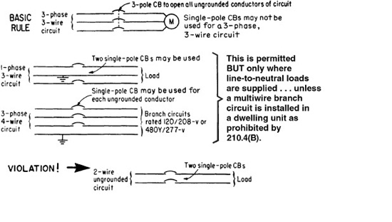
Although part (B) basically requires a CB to open all ungrounded conductors of a circuit simultaneously, parts (1), (2), and (3) cover acceptable uses of a number of single-pole CBs instead of multipole CBs.
The basic rule on use of single-pole versus multipole CBs is covered in this section.
Circuit breakers must open simultaneously all ungrounded conductors of circuits they protect; that is, they must be multipole CB units. The permission in (1) for use of single-pole breakers (and this is straight single-pole breakers, no handle ties needed) on multiwire branch circuits does not operate “where limited by 210.4(B),” and due to changes in 210.4(B) uncorrelated here, that limitation is now universal. In other words, since all multiwire branch circuits must have common disconnects (either handle ties or full two- or three-pole breakers) the “allowance” in this paragraph no longer exists.
The other two paragraphs allow handle-tied breakers for exclusively line-to-line loads such as baseboard electric heaters on grounded single-phase and grounded dc systems (2) and similar loads on polyphase systems (3).
Note: Two single-pole circuit breakers may not be used on “ungrounded 2-wire circuits”—such as 208-, 240-, or 480-V single-phase, 2-wire circuits. A 2-pole CB must be used if protection is provided by CBs. Use of single-pole CBs with handle ties but not common-trip is not allowed. This rule is intended to ensure that a ground fault will trip open both conductors of an ungrounded 2-wire circuit derived from a grounded system. However, use of fuses for protection of such a circuit is permitted even though it will present the same chance of a fault condition as shown in Fig. 240-12.

Fig. 240-11. A fuse or overcurrent trip unit must be connected in series with each ungrounded conductor. (Sec. 240.20.)


Fig. 240-12. Single-pole versus multipole breakers. (Sec. 240.15.)
Although 1-pole CBs may be used, as noted, it is better practice to use multi-pole CBs for circuits to individual load devices which are supplied by two or more ungrounded conductors. It is never wrong to use a multipole CB; but, based on the rules given here and in 210.4, it may be a violation to use two single-pole CB units. A 3-pole CB must always be used for a 3-phase, 3-wire circuit supplying phase-to-phase loads fed from an ungrounded delta system, such as 480-V outdoor lighting for a parking lot, as permitted by 210.6(B). In addition, there is a significant problem with availability of handle ties for three single-pole breakers used on three-phase wye multiwire branch circuits.
Refer also to 210.4 for limitation on use of single-pole protective devices with line-to-neutral loads. And 110.3(B) requires that use of single-pole CBs be related to UL rules as described in Fig. 240-13.
Part (C) of this section excludes “closed-loop power distribution systems” from the need for fuse or circuit-breaker protection. This paragraph, also uncor-related with developments elsewhere in the NEC, no longer has any effective
Fig. 240-13. NE Code rules must be correlated with these UL requirements. (Sec. 240.20.)
purpose. Such systems were covered by NEC Art. 780; however, that article was deleted for the 2008 NEC cycle for lack of interest. No such systems have been commercially installed beyond the first couple demonstration units some 20 years ago.
240.21. Location in Circuit. The basic rule of this section is shown in Fig. 240-14. A very important qualification that applies to all tap conductors is this: A tap cannot be tapped. Any conductor that originates under one of the provisions of 240.21(A through H) cannot supply any other conductor unless the next conductor has protection at its supply end with a conventional overcurrent device meeting all the rules in 240.4.
Fig. 240-14. Conductors must be protected at their supply ends. (Sec. 240.21.)
Although basic Code requirements dictate the use of an overcurrent device at the point at which a conductor received its supply, subparts (A) through (H) effectively present exceptions to this rule in the case of taps to feeders. That is, to meet the practical demands of field application, certain lengths of unprotected conductors may be used to tap energy from protected feeder conductors.
These “exceptions” to the rule for protecting conductors at their points of supply are made in the case of 10-, 25-, and 100-ft (3.0-, 7.5-, and 30.0-m) taps from a feeder, as described in 240.21, parts (B)(1), (B)(2), and (B)(4). Application of the tap rules should be made carefully to effectively minimize any sacrifice in safety. The taps are permitted without overcurrent protective devices at the point of supply.
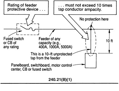
240.21(B)(1) says that unprotected taps not over 10 ft (3.0 m) long (Fig. 240-15) may be made from feeders, provided:
1. The smaller conductors have a current rating that is not less than the combined computed loads of the circuits supplied by the tap conductors and must have ampacity of—
Not less than the rating of the “device” supplied by the tap conductors.
(which formerly included the bus structure of a main lug only panelboard but given changes in 408.36, an overcurrent device is now generally required) or

Fig. 240-15. Ten-foot taps may be made from a feeder or a transformer secondary. (Sec. 240.21.)
Not less than the rating of the overcurrent device (fuses or CB) that is installed at the termination of the tap conductors.
Important Limitation: For any 10-ft (3.0-m) unprotected feeder tap installed in the field, the rule limits its connection to a feeder that has protection rated not more than 1000 percent of (10 times) the ampacity of the tap conductor where the tap conductors do not remain within the enclosure or vault in which the tap is made. This provision recognizes that taps present little threat while they remain within the confines of a transformer vault. It also recognizes the practical issues of sensor wiring within enclosures. For example, if a voltmeter is installed in the enclosure door of a 2000 A switchboard, 10 percent of 2000 A would otherwise require 3/0 conductors to run to the meter. Under the rule, unprotected No. 14 tap conductors are not permitted to tap a feeder any larger than 1000 percent of the 20-A ampacity of No. 14 copper conductors—which would limit such a tap for use with a maximum feeder protective device of not over 10 × 20 A, or 200 A.
2. The tap does not extend beyond the switchboard, panelboard, disconnect, or control device which it supplies.
3. The tap conductors are enclosed in conduit, EMT, metal gutter, or other approved raceway when not a part of the switchboard or panelboard.
240.21(C)(2) specifically recognizes that a 10-ft (3.0-m) tap may be made from a transformer secondary in the same way it has always been permitted from a feeder. In either case, the tap conductors must not be over 10 ft (3.0 m) long and must have ampacity not less than the amp rating of the switchboard, panel-board, disconnect, or control device—or the tap conductors may be terminated in an overcurrent protective device rated not more than the ampacity of the tap conductors. In the case of an unprotected tap from a transformer secondary, the ampacity of the 10-ft (3.0-m) tap conductors would have to be related through the transformer voltage ratio to the size of the transformer primary protective device—which in such a case would be “the device on the line side of the tap conductors.” Just as in the case of the feeder tap, there is a 1000 percent ratio limitation (in this case multiplied by the applicable transformer winding ratio) except once again where the secondary conductors don’t leave the vault or the enclosure where they originate the 1000 percent (10 times) factor does not apply.
Taps not over 25 ft (7.5 m) long (Fig. 240-16) may be made from feeders, as noted in part (B)(2) of 240.21, provided:
1. The smaller conductors have a current rating at least one-third that of the feeder overcurrent device rating or of the conductors from which they are tapped.
2. The tap conductors are suitably protected from mechanical damage. In previous Code editions, the 25-ft (7.5-m) feeder tap without overcurrent protection at its supply end simply had to be “suitably protected from physical damage”—which could accept use of cable for such a tap. Now, the rule requires such tap conductors to be “enclosed in an approved raceway or by other approved means”—strongly suggesting, but not quite mandating a raceway as has always been required for 10-ft (3.0-m) tap conductors.
3. The tap is terminated in a single CB or set of fuses which will limit the load on the tap to the ampacity of the tap conductors.
Figure 240-17 shows use of a 10-ft (3.05-m) feeder tap to supply a single motor branch circuit. The conduit feeder may be a horizontal run or a vertical run, such as a riser. If the tap conductors are of such size that they have a current rating at least one-third that of the feeder conductors (or protection rating) from
Fig. 240-16. Sizing feeder taps not over 25 ft (7.5 m) long. (Sec. 240.21.)
Fig. 240-17. A 10-ft (3.0-m) tap for a single motor circuit. (Sec. 240.21.)
which they are tapped, they could be run a distance of 25 ft (7.5 m) without protection at the point of tap-off from the feeder because they would comply with the rules of 240.21(B)(2), which permit a 25-ft (7.5-m) feeder tap if the conductors terminate in a single protective device rated not more than the conductor ampacity. 368.17(C) generally requires that any busway used as a feeder must have overcurrent protection on the busway for any subfeeder or branch circuit tapped from the busway. The use of a cable-tap box on a busway without over-current protection (as shown in the conduit installation of Fig. 240-17) would usually be a violation. But, Exception No. 1 to 368.17(C) clearly eliminates such protection where making taps. Refer to 240.24 and 368.17.
A common application of the 10-ft (3.0-m) tap is the supply of panelboards from conduit feeders or busways, as shown in Fig. 240-18. The case shows an interesting requirement that arises from 408.36, which requires that all panel-boards be protected on their supply side by overcurrent protection rated not more than the rating of the panelboard busbars. If the feeder is a busway, the protection must be placed [a requirement of 368.17(C)] at the point of tap on the busway. In that case a 100-A CB or fused switch on the busway would provide the required protection of the panel, and the panel would not require a main in it. But, if the feeder circuit is in conduit, the 100-A panel protection would have to be in the panel or just ahead of it.
Fig. 240-18. A 10-ft (3.0 m) tap to lighting panel with unprotected conductors. (Sec. 240.21.)
For transformer applications, typical 10- and 25-ft (3.0- and 7.5-m) tap considerations are shown in Fig. 240-19.
The bottom half of Fig. 240-19 illustrates an important concept that was just clarified in the 2008 NEC. A transformer (assuming appropriate capacity and primary-side protection) can supply any number of sets of secondary conductors, each of which is considered independently when applying the various rules for transformer secondary conductors covered in 240.21(C). If five sets of secondary conductors were supplied from a common secondary, in raceway and feeding a suitable overcurrent device at their load end, each could be 7.5 m (25 ft) long. It would not be necessary to keep them all 1.5 m (5 ft) long or other lengths such that the total did not exceed the 7.5 m (25 ft) limit overall.
Figure 240-20 shows application of part (B)(3) of 240.21 in conjunction with the rule of 450.3(B), covering transformer protection. As shown in Example 1, the 100-A main protection in the panel is sufficient protection for the
Fig. 240-19. Taps from transformer secondaries. (Sec. 240.21.)
Fig. 240-20. Feeder tap of primary-plus-secondary not over 25 ft (7.5 m) long. (Sec. 240.21.)
transformer and the primary and secondary conductors when these conditions are met:
1. Tap conductors have ampacity at least one-third that of the 125-A feeder conductors.
2. Secondary conductors are rated at least one-third the ampacity of the 125-A feeder conductors, based on the primary-to-secondary transformer ratio.
3. Total tap is not over 25 ft (7.5 m), primary plus secondary.
4. All conductors are in “approved raceway or other approved means.”
5. Secondary conductors terminate in the 100-A main protection that limits secondary load to the ampacity of the secondary conductors and simultaneously provides the protection required by the lighting panel.
6. Primary feeder protection is not over 250 percent of transformer rated primary current, as recognized by 450.3(B), and the 100-A main breaker in the panel satisfies as the required “overcurrent device on the secondary side rated or set at not more than 125 percent of the rated secondary current of the transformer.” Alternatively, if the primary protection meets the 125 percent rule in 450.3(B), the secondary protection would not be required for the transformer, and would therefore be limited only by the requirements of protecting the secondary conductors and of protecting the panelboard.
Frequently the wiring under this rule uses conductors on the line side of the transformer that are not reduced in any way from the size of the conductors of the feeder to which they are connected. In this case, the length of wire on the primary size that has to be figured in to the 7.5 m (25 ft) limitation under this rule is zero, and the secondary conductors can take the full 7.5 m (25 ft) if necessary.
Example 2 of Fig. 240-20 shows multiple sets of tap conductors from the primary feeder to a group of transformers. In such cases the primary taps are frequently reduced because the primary feeder must have the capacity for several load groups. In such cases the length of the primary side is not zero, and must be subtracted from the permitted overall total. The allowable protection for that parent feeder must meet both 240.4 for the feeder conductors employed, and also provide protection for each of the transformers supplied, at a value therefore based on 250 percent of the primary rating of the smallest transformer served. Figure 240-21 shows this process at work, although in this example the primary conductors were not reduced in size, allowing a full-length secondary.
Fig. 240-21. Sizing a 25-ft (7.5 m) tap and transformer protection. (Sec. 240.21.)
This is as good an illustration of any of a crucial principle that we will discuss again in 450.3, namely, the rules in Art. 240 for conductor protection stand alone from the rules in Art. 450 for transformer protection. However, if it is intended that a single protective device perform both functions, then both sets of rules must be applied. Make separate calculations, and select for the worst case. If the result is one you don’t want to live with, add additional devices until you do meet all the rules.
Figure 240-22 compares the two different 25-ft (7.5-m) tap techniques covered by part (B)(2) and the equivalent distance with a transformer secondary

Fig. 240-22. Examples show difference between the two types of 25-ft (7.5 m) taps covered by parts (C) and (C)(5). (Sec. 240.21.)
interposed, 240.21(C)(5), as just covered in 240.21(B)(3). This rule in part (C) simply provides correlation with 240.21(B)(3) because that other rule also covers a transformer secondary.
Part (B)(4) is another departure from the rule that conductors must be provided with overcurrent protection at their supply ends, where they receive current from larger feeder conductors. 240.21(B)(4) permits a longer length than the 10-ft unprotected tap of part (B)(1) and the 25-ft (7.5-m) tap of part (B)(2). Under specified conditions that are similar to the requirements of the 25-ft-tap exception, an unprotected tap up to 100 ft (30.0 m) in length may be used in “high-bay manufacturing buildings” that are over 35 ft (11.0 m) high at the walls—but only “where conditions of maintenance and supervision assure that only qualified persons will service the system.” Obviously, that last phrase can lead to some very subjective and individualistic determinations by the authorities enforcing the Code. And the phrase “35 ft (11.0 m) high at the walls” means that this rule cannot be applied where the height is over 35 ft (11.0 m) at the peak of a triangular or curved roof section but less than 35 ft (11.0 m) at the walls.
The 100-ft (30.0-m) tap exception must meet specific conditions:
1. “Qualified” persons must maintain the system.
2. From the point at which the tap is made to a larger feeder, the tap run must not have more than 25 ft (7.5 m) of its length run horizontally, and the sum of horizontal run and vertical run must not exceed 100 ft (30.0 m). Figure 240-23 shows some of the almost limitless configurations of tap layout that would fall within the dimension limitations.
Fig. 240-23. Unprotected taps up to 100 ft long may be used in “high-bay manufacturing buildings.”
3. The tap conductors must have an ampacity equal to at least one-third of the rating of the overcurrent device protecting the larger feeder conductors from which the tap is made.
4. The tap conductors must terminate in a circuit breaker or fused switch, where the rating of overcurrent protection is not greater than the tap-conductor ampacity.
5. The tap conductors must be protected from physical damage and must be installed in “an approved raceway or other approved means.”
6. There must be no splices in the total length of each of the conductors of the tap.
7. The tap conductors must not be smaller than 6 AWG copper or 4 AWG aluminum.
8. The tap conductors must not pass through walls, floors, or ceilings.
9. The point at which the tap conductors connect to the feeder conductors must be at least 30 ft (9.0 m) above the floor of the building.
As shown in Fig. 240-23, the tap conductors from a feeder protected at 1200 A are rated at not less than one-third the protection rating, or 400 A. Although 500-kcmil THW copper is rated at 380 A, that value does not satisfy the minimum requirement for 400 A. But if 500-kcmil THHN or XHHW copper, with an ampacity of 430 A, were used for the tap conductors, the rule would be satisfied. However, in such a case, those conductors would have to be used as if their ampacity were 380 A for the purpose of load calculation because of the general UL rule of 75°C conductor terminations for connecting to equipment rated over 100 A—such as the panelboard, switch, motor-control center, or other equipment fed by the taps. And the conductors for the main feeder being tapped could be rated less than the 1200 A shown in the sketch if the 1200-A protection on the feeder was selected in accordance with 430.62 or 430.63 for supplying a motor load or motor and lighting load. In such cases, the overcurrent protection may be rated considerably higher than the feeder conductor ampacity. But the tap conductors must have ampacity at least equal to one-third the feeder protection rating.
The 1200-A feeder that was tapped in this example raises another point of discussion. That feeder, unless from a busway, almost certainly was run with multiple conductors in parallel. For the sake of argument, suppose the feeder consists of three sets of 600-kcmil conductors. The 400-A tap, as noted, could be 500 kcmil THHN. The question constantly arises in the field, is it necessary to connect each phase of the tap to all of the corresponding phase conductors in the overhead feeder? Certainly tapping only one of those conductors would be a far simpler task. The answer is no.
The feeder as connected to its overcurrent protective device is all three runs. Separating one of the sets of the supplied conductors means that the tap is being applied to only one-third of the feeder. In effect the tap is being made to another tap, namely, one that begins at the 1200 A breaker. That tap would not comply with any known allowance in the NEC given its length, location, etc. Further, the actual field tap covered here would then be made from this undefined tap, in violation of the clear prohibition of making taps from other taps.
240.21(C)(3) applies exclusively to industrial electrical systems. Conductors up to 25 ft (7.5 m) long may be tapped from a transformer secondary without overcurrent protection at their supply end and without need for a single-circuit breaker or set of fuses at their load end. Normally, a transformer secondary tap over 10 ft (3.0 m) long and up to 25 ft (7.5 m) long must comply with the rules of 240.21(C)(5) or (C)(6)—which call for such a transformer secondary tap to be made with conductors that require no overcurrent protection at their supply end but are required to terminate at their load end in a single CB or single set of fuses with a setting or rating not over the conductor ampacity. However, 240.21(C)(3) permits a 10- to 25-ft (3.0- to 7.5-m) tap from a transformer secondary without termination in a single main overcurrent device—but it limits the application to “industrial installations.” The tap conductor ampacity must be at least equal to the transformer’s secondary current rating and must be at least equal to the sum of the ratings of overcurrent devices supplied by the tap conductors.
As a practical matter, this provision appears to be limited to tap conductors arriving at the main lugs of a switchboard, as in Fig. 240-24. A motor control center could not qualify, because overcurrent protection in the form of a
Fig. 240-24. These tap applications are permitted for transformer secondaries only in “industrial” electrical systems.
singular device is required in accordance with the rating of the common power bus, as covered in 430.94. Power panels no longer comply because all panelboards now require individual overcurrent protection, with exceptions that would not apply here (see 408.36). If the tap arrived at a wireway or auxiliary gutter over the collection of loads intended to be supplied, as shown at the bottom of Fig. 240-24, the individual taps to each of the loads would arguably violate the prohibition against tapping taps, certainly so if they were reduced in size to meet the likely termination limitations of the smaller equipment.
The rule of parts (B)(5) and (C)(4) allows outdoor feeder taps and unprotected secondary conductors from outdoor transformers to run for any distance outdoors. Physical protection for the conductors must be provided and they must terminate in a single CB or set of fuses. The CB or set of fuses must be part of, or adjacent to, the disconnect, which may be installed anywhere outdoors or indoors as close as possible to the point of conductor entry. Both sections emphasize that such unprotected conductors must not be run within any building or structure. As is the case with service conductors, these tap conductors must be terminated at an OC device as soon as they enter. Also, as in the case of services, the rules of 230.6 (concrete encasement, etc.) can be used to artificially extend the point of entrance if necessary.
As shown in Fig. 240-25, 240.21(G) gives permission for unprotected taps to be made from generator terminals to the first overcurrent device it supplies—such as in the fusible switch or circuit breakers used for control and protection of the circuit that the generator supplies. No maximum length is specified for the generator tap conductors, although various limits have been proposed over the years. Note also that 445.13, which is referenced, requires the tap conductors to have an ampacity of at least 115 percent of the generator nameplate current rating.
Fig. 240-25. Unprotected tap may be made from a generator’s output terminals to the first overcurrent device. [Sec. 240.21(G).]
Section 240.21(H), new in the 2008 NEC, allows the location of overcurrent protection for battery output conductors to be as close as practicable to the battery room and still be out of range of the hazardous location boundary, if such a classification has been established. Note that 480.5 requires the disconnecting means for conductors supplied from a stationary battery system operating over 30 V to be readily accessible and within sight of the battery system. While batteries are charging, the current flowing over the conductors is controlled by the charging system, but when the batteries are actually supplying power overcurrent protection is necessary.
240.22. Grounded Conductors. The basic rule prohibits use of a fuse or CB in any conductor that is intentionally grounded—such as a grounded neutral or a grounded phase leg of a delta system. Figure 240-26 shows the two “exceptions” to that rule and a clear violation of the basic rule.
240.23. Change in Size of Grounded Conductor. In effect, this recognizes the fact that if the neutral is the same size as the ungrounded conductor, it will be protected wherever the ungrounded conductor is protected. One of the most obvious places where this is encountered is in a distribution center where a small grounded conductor may be connected directly to a large grounded feeder conductor.
240.24. Location in or on Premises. According to part (A), overcurrent devices must be readily accessible. And in accordance with the definition of “readily accessible” in Art. 100, they must be “capable of being reached quickly for operation, renewal, or inspections, without requiring those to whom ready access is requisite to climb over or remove obstacles or to resort to portable ladders, chairs, etc.” (Fig. 240-27).
Although the Code gives no maximum heights at which overcurrent protective devices are considered readily accessible, some guidance can be obtained from 404.8, which provides detailed requirements for location of switches and CBs. This section states that switches and CBs shall be so installed that the center of the grip of the operating handle, when in its highest position, will not be more than 6 ft 7 in. (2.0 m) above the floor or working platform.
There are certain applications where the rules for ready accessibility are waived.
Part (A)(1) covers any case where an overcurrent device is used in a busway plug-in unit to tap a branch circuit from the busway. 368.12 requires that such devices consist of an externally operable CB or an externally operable fusible switch. These devices must be capable of being operated from the floor by means of ropes, chains, or sticks. Part (A)(2) refers to 240.10, which states that where supplementary overcurrent protection is used, such as for lighting fixtures, appliances, or internal circuits or components of equipment, this supplementary protection is not required to be readily accessible. An example of this would be an overcurrent device mounted in the cord plug of a fixed or semifixed luminaire supplied from a trolley busway or mounted on a luminaire that is plugged directly into a busway. Part (A)(3) acknowledges that 230.92 permits service overcurrent protection to be sealed, locked, or otherwise made not readily accessible. Figure 240-28 shows these details.
Fig. 240-26. Overcurrent protection in grounded conductor. (Sec. 240.22.)
Fig. 240-27. Overcurrent devices must be “readily accessible.” (Sec. 240.24.)
240.24 clarifies the use of plug-in overcurrent protective devices on busways for protection of circuits tapped from the busway. After making the general rule that overcurrent protective devices must be readily accessible (capable of being reached without stepping on a chair or table or resorting to a portable ladder), part (A)(1) notes that it is not only permissible to use busway protective devices up on the busway—it is required by 368.17(C). Such devices on high-mounted busways are not “readily accessible” (not within reach of a person standing on the floor). The wording of 368.17(C) makes clear that this requirement for over-current protection in the device on the busway applies to subfeeders tapped from the busway as well as branch circuits tapped from the busway.
The rule of (A)(4) recognizes the installation of an OC device in an inaccessible location where mounted adjacent to “utilization equipment they supply.” The term “equipment” is defined in Art. 100. That definition seems to give broad permission for application of this rule. It seems that locating OC devices for conductor protection in other than a readily accessible location would not

Fig. 240-28. Fuses or CBs that are permitted to be not readily accessible. (Sec. 240.24.)
be permitted. Clearly, for motors, appliances, and transformers, the OC device that supplies such “equipment” may be mounted in an inaccessible location. The rules of NE Code 240.24, 368.17(C), and 404.8 must be correlated with each other to assure effective Code compliance.
Part (B) applies to apartment houses and other multiple-occupancy buildings—such as hotel guest rooms and suites, as described in Fig. 240-28.
In addition, it is important to note that parts (C) and (D) of 240.24 require that overcurrent devices be located where they will not be exposed to physical damage or in the vicinity of easily ignitable material. Panelboards, fused switches, and circuit breakers may not be installed in clothes closets in any type of occupancy—residential, commercial, institutional, or industrial. But they may be installed in other closets that do not have easily ignitable materials within them—provided that the working clearances of 110.26 (30-in. [752 mm] wide work space in front of the equipment, 6 ft 6 in. [2.0-m] headroom, illumination, etc.) are observed and the work space is “not used for storage,” as required by 110.26(B).
240.24(E) flatly prohibits what was a somewhat common practice for dwellings, as well as guest rooms and suites in hotels and motels. In certain areas of the nation, overcurrent protective devices were located in areas such as kitchens and bathrooms. Although it is still permissible to locate the overcurrent protective devices in the kitchen, the rule of part (E) now forbids location of the overcurrent devices within the bathroom of a dwelling or hotel guest room or suite.
Part (F), new for the 2008 NEC, flatly prohibits locating overcurrent devices over the inclined portion of a stairway. The literal text prohibits the location over “steps” which is presumably different from a “landing.” There is no dimension given as to when a step becomes wide enough to be a landing, but that should be relatively obvious and interpreted consistently. Presumably the required workspace width would be a good starting point.
240.33. Vertical Position. Figure 240-29 shows the basic requirements of 240.30, 240.32, and 240.33. The rule in 240.33 is frequently misunderstood as favoring
Fig. 240-29. Enclosures for overcurrent protection. (Sec. 240.30.)
vertical mounting in the sense of having the operator move up and down, as distinguished from moving from side to side. That is the topic of 240.81 but is incorrect here. This section addresses the plane in which the overcurrent device is mounted, and favors a vertical plane as in mounting on a wall, and discourages mounting in a horizontal plane as in face up or face down.
This rule has been in the NEC for over 80 years, having first appeared in the 1926 edition. The commentary in the 8th edition of this Handbook, on the 1953 NEC, is instructive as to the intent of this rule:
Installing cabinets or cutout boxes on ceilings is a practice that should be avoided wherever possible. Section 2435 [corresponds to 240.24 in the 2008 NEC.] calls for cutouts and circuit breakers to be readily accessible, and a box on a ceiling is seldom readily accessible. In a box so installed, one end of a cartridge fuse may fall out of the terminals and make contact with the door of the box, thus grounding the circuit.
In addition to ceiling mounting issues, there have been some occasions for horizontal mounting in other circumstances. Some small panels, with perhaps four to six circuits, have been horizontally mounted, face-up with a door, in the top section of a short but deep wall housing special equipment. The circuit breakers were readily accessible, there was no good alternative, and the inspector agreed with the result. That said, wall mounting is almost always preferable. The rule also makes allowances for listed busway plug-in units that may have been designed for a horizontal orientation when the busway is in certain positions.
240.40. Disconnecting Means for Fuses. The basic rules are shown in Fig. 240-30. The second sentence covers cable limiters, and as covered in 230.82(1) they can be located ahead of the service disconnect, where no switch is required. The rule presented by the last sentence is illustrated in Fig. 240-31.
240.50. General (Plug Fuses). Plug fuses must not be used in circuits of more than 125 V between conductors, but they may be used in grounded-neutral systems where the circuits have more than 125 V between ungrounded conductors but not more than 150 V between any ungrounded conductor and ground (Fig. 240-32). And the screw-shell of plug fuseholders must be connected to the load side of the circuit.
240.51. Edison-Base Fuses. 240-52. Edison-Base Fuseholders. 240-53. Type S Fuses. 240.54. Type S Fuses, Adapters, and Fuseholders. Rated up to 30 A, plug fuses are Edison-base or Type S. 240.51(B) limits the use of Edison-base fuses to replacements of existing fuses of this type, and even then, they must be replaced if there is evidence of tampering or overfusing. Type S plug fuses are required by 240.53 for all new plug-fuse installations, and 240.52 requires new Edison-base fuseholders to be converted to Type S. These adapters are designed to go in but not come out. Once converted to Type S, an Edison-base fuseholder cannot be unconverted without the use of a special tool that destroys the adapter in the process. An unqualified person is unlikely to successfully attempt this process. Type S plug fuses must be used in Type S fuseholders or in Edison-base fuse-holders with a Type S adapter inserted, so that a Type S fuse of one ampere classification cannot be replaced with a higher-amp rated fuse (Fig. 240-33). Type S fuses, fuseholders, and adapters are rated for three classifications based on amp
Fig. 240-30. Disconnect means for fuses. (Sec. 240.40.)
Fig. 240-31. Single disconnect for one set of fuses is permitted for electric space heating with subdivided resistance-type heating elements. (Sec. 240.40.)
Fig. 240-32. Using plug fuses. (Sec. 240.50.)
Fig. 240-33. Type S plug fuse. (Sec. 240.53.)
rating and are noninterchangeable from one classification to another. The classifications are 0 to 15, 16 to 20, and 21 to 30 A. The 0- to 15-A fuseholders or adapters must not be able to take any fuse rated over 15 A, etc. The purpose of this rule is to prevent overfusing of 15- and 20-A circuits.
240.60. General (Cartridge Fuses). The last sentence of part (B) must always be carefully observed. It is concerned with an extremely important matter:
The installation of current-limiting fuses demands extreme care in the selection of the fuse clips to be used. Because current-limiting fuses have an additional protective feature (that of current limitation, that is, extremely fast operation to prevent the flow of the extremely high currents which many modern circuits can produce into a ground fault or short circuit) as compared to noncurrent-limiting fuses, some condition of the mounting arrangement for current-limiting fuses must prevent replacement of the current-limiting fuses by noncurrent-limiting. This is necessary to maintain safety in applications where, for example, the busbars of a switchboard or motor control center are braced in accordance with the maximum let-through current of current-limiting fuses which protect the busbars, but would be exposed to a much higher potential value of fault let-through current if noncurrent-limiting fuses were used to replace the current-limiting fuses. The possibility of higher current flow than that for which the busbars are braced is created by the lack of current limitation in the noncurrent-limiting fuses.
240.60(B) takes the above matter into consideration when it rules that “fuse-holders for current-limiting fuses shall not permit insertion of fuses that are not current limiting.” To afford compliance with the Code and to obtain the necessary safety of installation, fuse manufacturers provide current-limiting fuses with special ferrules or knife blades for insertion only in special fuse clips. Such special ferrules and blades do permit the insertion of current-limiting fuses into standard NEC fuse clips, to cover those cases where current-limiting fuses (with their higher type of protection) might be used to replace noncurrent-limiting fuses. But the special rejection-type fuseholders will not accept noncurrent-limiting fuses—thereby ensuring replacement only with current-limiting fuses.
The very real problem of Code compliance and safety is created by the fact that many fuses with standard ferrules and knife-blade terminals are of the current-limiting type and are made in the same construction and dimensions as corresponding sizes of noncurrent-limiting fuses, for use in standard fuse-holders. Such current-limiting fuses are not marked “current limiting” but may be used to obtain limitation of energy let-through. Replacement of them by standard nonlimiting fuses could be hazardous. Note that 240.60(C) covers the required markings on fuses, and in this regard pay close attention to the interrupting rating, which must always be marked if other than the default value of 10,000 A.
Class J and L fuses Both the Class J (0 to 600 A, 600 V AC) and Class L (601 to 6000 A, 600 V AC) fuses are current-limiting, high-interrupting-capacity types. The interrupting ratings are 100,000 or 200,000 rms symmetrical amperes, and the designated rating is marked on the label of each Class J or L fuse. Class J and L fuses are also marked “current limiting,” as required in part (C) of 240.60.
Class J fuse dimensions are different from those for standard Class H cartridge fuses of the same voltage rating and ampere classification. As such, they will require special fuseholders that will not accept noncurrent-limiting fuses. This arrangement complies with the last sentence of NEC 240.60(B).
Class K fuses These are subdivided into Classes K-1, K-5, and K-9. Class K fuses have the same dimensions as Class H (standard NE Code) fuses and are interchangeable with them. Classes K-1, K-5, and K-9 fuses have different degrees of current limitation but are not permitted to be labeled “current limiting” because physical characteristics permit these fuses to be interchanged with noncurrent-limiting types. Use of these fuses, for instance, to protect equipment busbars that are braced to withstand 40,000 A of fault current at a point where, say, 60,000 A of current would be available if noncurrent-limiting fuses were used is a clear violation of the last sentence of part (B). As shown in Fig. 240-34, because such fuses can be replaced with nonlimiting fuses, the equipment bus structure would be exposed to dangerous failure. Classes R and
Fig. 240-34. Current-limiting fuseholders must be rejection type. (Sec. 240.60.)
T have been developed to provide current limitation and prevent interchange-ability with noncurrent-limiting types.
Class R fuses These fuses are made in two designations: RK1 and RK5. UL data are as follows:
Fuses marked “Class RK1” or “Class RK5” are high-interrupting-capacity types and are marked “current limiting.” Although these fuses will fit into standard fuseholders that take Class H and Class K fuses, special rejection-type fuseholders designed for Class RK1 and RK5 fuses will not accept Class H and Class K fuses. In that way, circuits and equipment protected in accordance with the characteristics of RK1 or RK5 fuses cannot have that protection reduced by the insertion of other fuses of a lower protective level.
Other UL application data that affect selection of various types of fuses are as follows:
Fuses designated as Class CC (0 to 20 A, 600 V AC) are high-interrupting-capacity types and are marked “current limiting.” They are not interchangeable with fuses of higher voltage or interrupting rating or lower current rating.
Class G fuses (0 to 60 A, 300 V AC) are high-interrupting-capacity types and are marked “current limiting.” They are not interchangeable with other fuses mentioned preceding and following.
Fuses designated as Class T (0 to 600 A, 250 and 600 V AC) are high-interrupting-capacity types and are marked “current limiting.” They are not interchangeable with other fuses mentioned previously.
Part (C) requires use of fuses to conform to the marking on them. Fuses that are intended to be used for current limitation must be marked “current limiting.”
Class K-1, K-5, and K-9 fuses are marked, in addition to their regular voltage and current ratings, with an interrupting rating of 200,000, 100,000, or 50,000 A (rms symmetrical). (See Fig. 240-35.)
Class CC, RK1, RK5, J, L, and T fuses are marked, in addition to their regular voltage and current ratings, with an interrupting rating of 200,000 A (rms symmetrical).
Fig. 240-35. Fuses must be applied in accordance with marked ratings. (Sec. 240.60.)
Although it is not required by the Code, manufacturers are in a position to provide fuses that are advertised and marked indicating they have “time-delay” characteristics. In the case of Class CC, Class G, Class H, Class K, and Class RK fuses, time-delay characteristics of fuses (minimum blowing time) have been investigated. Class G or CC fuses, which can carry 200 percent of rated current for 12 s or more, and Class H, Class K, or Class RK fuses, which can carry 500 percent of rated current for 10 s or more, may be marked with “D,” “time delay,” or some equivalent designation. Class L fuses are permitted to be marked “time delay” but have not been evaluated for such performance. Class J and T fuses are not permitted to be marked “time delay.”
240.61. Classification. This section notes that any fuse may be used at its voltage rating or at any voltage below its voltage rating.
240.80. Method of Operation (Circuit Breakers). This rule requiring trip-free manual operation of circuit breakers ties in with that in 230.76, although this rule requires manual operation to both the closed and the open positions of the CB. According to 230.76, a power-operated circuit breaker used as a service disconnecting means must be capable of being opened by hand but does not have to be capable of being closed by hand. The general rule of 240.80 requires circuit breakers to be “capable of being closed and opened by manual operation.” That rule also says that if a CB is electrically or pneumatically operated, it must also provide for manual operation (Fig. 240-36).
240.81. Indicating. This rule requires the up position to be the ON position for any CB. All circuit breakers—not just those “on switchboards or in panelboards”—must be ON in the up position and OFF in the down position if their handles operate vertically rather than rotationally or horizontally. This is an expansion
Fig. 240-36. Every CB must be manually operable. (Sec. 240.80.)
of the rule that previously applied only to circuit breakers on switchboards or in panelboards. This brings the rule into agreement with that of the second paragraph of 404.7—which makes the identical requirement for all circuit breakers and switches in individual enclosures. Switches and circuit breakers in individual enclosures must be marked to clearly show ON and OFF positions and vertically operated switches and CBs must be ON when in the up position (Fig. 240-37).
Fig. 240-37. Handle position of CB in any kind of enclosure must be ON in the up position. (Sec. 240.81.)
240.83. Marking. Part (A) requires that the marking of a CB’s ampere rating must be durable and visible after installation. That marking is permitted to be made visible by removing the trim or cover of the CB.
In part (B), the Code mandates that the ampere rating be marked on the CB’s handle (or escutcheon area) when it is rated 100 A or less. Part (C) presents the same requirement that UL does with regard to the marking of the OC device’s ampere interrupting rating (AIR). Where an OC device has more than a 5000 AIR, the AIR must be marked on the CB by the manufacturer.
Part (D) of this section requires that any CB used to switch 120- or 277-V fluorescent lighting be listed for the purpose and be marked “SWD” or “HID.” Note that the “HID” rating is somewhat more robust, and therefore such a breaker can be used for fluorescent lighting, but the reverse is not the case and an “SWD” breaker is only good for fluorescent lighting (Fig. 240-38). In commercial and industrial electrical systems, ON-OFF control of lighting is commonly done by the breakers in the lighting panel, eliminating any local wiring-device switches. Be careful to integrate the requirements in 210.4(B) with this process on new installations. If the lighting circuits are configured as multiwire branch circuits, multipole breakers will generally be in order, and a much larger area will go off and on when the breaker operates. However, with the recent focus on energy conservation, large numbers of these lighting zones are being provided with occupancy sensors or other automated methods to run the lights only where needed, so this is probably not the concern it was years ago.
The rule of part (E) requires specific voltage markings on circuit breakers.
Fig. 240-38. Circuit breakers used for switching lights must be SWD type. [Sec. 240.83(D).]
240.85. Applications. This section repeats UL data regarding interpretation of voltage markings. The wording explains circuit-breaker voltage markings in terms of the device’s suitability for grounded and ungrounded systems. Designation of only a phase-to-phase rating—such as “480 V”—indicates suitability for grounded or ungrounded systems. But voltage designations showing a phase-to-neutral voltage by “slash” markings—like 480Y/277 V or 120/240 V—indicate that such circuit breakers are limited exclusively to use in grounded neutral electrical systems. Specifically, a slash-rated breaker must only be used where all ungrounded conductors to which it will be connected operate at the lower voltage to ground. This makes a real difference in a center-tapped delta system (capable of traditional three-phase 240-V connections and 120/240-V connections across one pair of phases). The other phase, the so-called high leg, will be at 208 V to ground on such systems. Any two-pole circuit breaker connected to the high leg will (1) be operating correctly in terms of line-to-line voltage, but (2) operating beyond its ratings in terms of line-to-ground voltage. A line-to-ground fault will require the breaker to clear a fault that is in progress using only one of its poles at a significantly higher voltage than it was tested.
Breakers without the slash markings are internally braced to withstand and clear full line-to-line voltage faults that can easily flow through only one pole of the breaker, particularly on corner-grounded systems. This requires a far more robust construction than the usual grounded neutral system, where any ground fault that involves only one pole will be at only the line-to-neutral voltage, and for any line-to-line short circuit the interrupting effort will be shared between two poles of the breaker. For this reason track this rule carefully when laying out jobs. Three-pole breakers are generally available without relying on a slash marking, but two-pole breakers without the slash markings are frequently only available by special order and sell at a substantial cost premium.
The last sentence in the first part of Sec. 240.85 calls attention to the marking that identifies a two-pole breaker’s suitability for use on corner-grounded systems. Two-pole devices marked 240 or 480 V must be further identified by a marking “1 -3” to be used on corner-grounded delta systems. These breakers undergo special testing, including some consideration of the “individual pole interrupting capability” discussed in the fine-print note at the end of the section.
240.86. Series Ratings. This section recognizes the use of the “series-rated” OC devices to ensure adequate fault-current protection. These devices, when operated in series with each other, allow the fault-interrupting capability of the main breaker, under fault conditions, to assist feeder or branch breakers that are applied at a point in the distribution system where the available fault current is greater than the AIR of the feeder or branch breaker. By sharing the arc, and operating in series, the circuit components will be provided the protection required by 110.10, even though a downstream protective device in the series may not have an adequate AIR for the point in the system where it is installed. Application of such overcurrent protective devices must satisfy the requirements given here.
When considering the concept of series rated circuit breakers, a key controversy quickly arises, and most of the changes in this part of the NEC over the last several code cycles have involved attempts to address this concern. This is the question of how to deal with dynamic impedance. When a circuit breaker trips and begins the process of clearing a fault, its contacts begin to separate and as they do, they draw an arc. Electrical arcs have significant impedance, and that impedance changes rapidly as the internal contacts separate. This is an oversimplification, however, the contacts of a smaller breaker, having less inertia, may open more quickly than those of a larger breaker. In the worst case, the smaller breaker can introduce just enough impedance into the circuit that the larger breaker may not unlatch, and ride out the fault. Assuming the fault was well beyond the interrupting rating of the smaller breaker, the consequence of the upstream large breaker riding out the fault can easily result in the complete destruction of the downstream breaker.
It turns out that this process is very difficult to accurately predict by engineering modeling, even with second-order differential equations. Therefore, the circuit breaker manufacturers have resigned themselves to bench testing every conceivable combination of breakers in their product lines. The result is the “tested combinations” of 240.86(B), and the mandated marking required in 110.22(C). (See Fig. 240-39 for an example.) Every combination marked on a panelboard label has been bench tested to verify that the combination of this large breaker ahead of that small breaker, ranging from comparatively low fault to the specified maximum available fault current under prescribed test conditions, will clear and both upstream and downstream devices will live to protect again after the interruption is complete. These combinations undergo intermediate testing as well as testing under maximum fault current exposures to ensure that the combination will function in accordance with applicable standards under any overcurrent applied, not just bolted fault conditions. If a combination fails, the manufacturer has two choices: either leave that combination off the label, or make subtle changes in his breakers so the combination will pass reliably.
Fig. 240-39. An “additional series combination interrupting rating” must be “marked” on equipment. (Sec. 240.86.)
However, not all combinations, particularly combinations involving obsolete breakers, can be tested, and available fault currents steadily increase as the utility infrastructure stiffens in response to population increases and demands for increased reliability. If that upgrade crosses the previously designed available fault current line at a major industrial facility, the result is that large sections of the facility distribution system may drop dangerously below the interrupting ratings of the existing protective devices. To preserve safety, the facility must now consider buying and installing completely new gear with available fault current ratings that ensure appropriate performance under all overcurrent conditions. This process could involve, quite clearly, an astronomical expense.
That being the case, facilities that have been confronted by this exposure have tried to find a way to address it in some other way, and the fuse industry would love to be part of the solution. For decades the fuse industry has published “let through” calculations and data on their products. The customary approach is what is called an “up-over-and-down” analysis using published current limiting graphs for the style of fuse considered. Beginning with the available rms fault current on the horizontal axis, read straight up to the diagonal index line for the proposed fuse size, then straight over to a line at a 45° slope, and then read straight down to the horizontal axis once again. The number there is the worst-case let-through rms current for the fuse in question when it is applied in the system being analyzed. If that number is less than interrupting rating of the old circuit breakers, can the problem be solved by adding a fuse?
Not necessarily because the dynamic impedance problem can defeat this design. If, and only if the circuit breaker can be guaranteed to not unlatch for several cycles, then yes, problem solved. And there are some old air-frame power breakers that won’t unlatch for three cycles or so, giving the fuse time to clear the fault. But modern molded case circuit breakers have mechanisms, even those that aren’t officially current limiting, that have internal current paths for which the magnetic forces on large faults tend to oppose each other and blow the contacts apart. The fault is often not a bolted fault but an arcing fault. If that happens and the arc adds enough impedance to take the current below the current limiting range of the fuse, then the fuse will delay its response and the breaker will take the hit. It is not always impossible to design for this, but frequently very difficult to impossible. This brings us to current NEC requirements.
In addition to bench-tested combinations in 240.86(B), there now exists a procedure to field engineer a series-connected rating, as given in 240.86(A). There are significant restrictions on this approach. First, the procedure can only be used in an existing facility. It must be designed by a licensed professional engineer with appropriate training. He or she must document the selection and stamp the design, which must be made available to the local inspector and all others who will be working with the system. The rating, including the identity of the downstream device, must be field marked on the end use equipment in the manner specified in 110.22(B).
This entire issue continues as one of the most difficult to address in the history of the NEC for a particularly compelling reason. Both sides are right. The circuit breaker manufacturers are right to object to oversimplifications by some who market fuses. And the fuse manufacturers are right to point to the astronomical expenses involved in reworking existing plant, and the existence of at least some applications that seem amenable to field engineering. Remember that 90.1(B) doesn’t promise electrical installations will be free from hazard, only that they will be essentially free from hazard. So the limited engineering approach has merit, but just when this author was getting comfortable with the 2005 NEC provisions that ushered this approach into the NEC, along comes documented adverse experience where a facility applied the field engineering process. The methodology appeared to this author to have been competent. Fortunately, the owner was willing to pay to have the engineered combination tested. All five tests failed and the project was redesigned with a separate transformer vault that subdivided the load through smaller gear and avoided the problem. Had the actual bench testing not been done, the engineer would have stamped the plans and this system would be in service today.
To this end, the 2008 NEC now incorporates an additional paragraph that requires the engineer to ensure that the downstream breaker(s) that are part of the series design remain passive while the upstream current-limiting device is interrupting the fault. It remains to be seen how many engineers will put their professional status on the line to offer such assurances. It is significant that both the UL and NEMA representatives on the panel remain opposed this procedure. Of equal significance is the fact that the allowance remains in the NEC, having retained the necessary consensus of the panel. Remember, both sides are right. This controversy will continue.
Part (C) in this section addresses the concern related to applications where motor contribution to downstream faults may render the “lower-rated” device incapable of safely clearing the faulted circuit. Remember that at the instant of an outage a rotating motor is a generator, fully capable of adding current. Any short-circuit current study necessarily considers motor contributions to the fault current available. In any application of “series-rated” OC devices, if the “sum” of motor full-load currents that may be contributed to the lower-rated device—without passing through the higher-rated device—exceeds the lower-rated device’s rating by 1 percent (e.g., 100 A of contributed motor current to a 10,000-AIR device), then series-rated devices may not be used. This disqualification applies to both bench-tested applications in (B) and to field engineered combinations in (A) because the parent language in the section requires compliance with (A) or (B) as applicable, and (C) in all cases.
Part VIII. Supervised Industrial Installations A supervised industrial installation is limited to the industrial portions of a facility that meet the following three criteria:
There is qualified maintenance and engineering supervision such that only qualified personnel are running the system.
The premises electrical system supporting the industrial processes or manufacturing activities or both (and not including any office or other indirect support loads) has a calculated load per Art. 220 that is not less than 2500 kVA.
The premises electrical system is comprised of not less than one service or feeder that runs over 150 V to ground and over 300 V phase-to-phase.
These installations must comply with all requirements in Art. 240, except as modified in this part. And any such modifications that are applied in the facilities must not extend beyond the manufacturing or process control environment. The principal impacts of the modifications here involve four amendments to the tap rules in 240.21, as follows:
240.92(B) provides that a short-circuit analysis can be performed based on the short-circuit current rating of the conductors to be protected, using a table that is long familiar to the electrical engineering community but that is new to the NEC. If sensors are arranged to monitor the variables that make up the table formulas, then there will be no adverse outcome.
240.92(C) allows transformer secondary conductors to be protected using an approach that divorces the short-circuit and ground-fault protection from the overload protection function. The short-circuit and ground-fault protection can be arranged in one of three ways by 240.92(C)(1). The first option liberalizes the winding-ratio limitation of 240.21(C)(1) by allowing secondary conductors, even those extended from a multiwire secondary, to run up to 30 m (100 ft) with primary side protection only, set at not more than 150 percent of tap ampacity after adjusting for the winding ratio. The second option recognizes a differential current relay arranged to operate a shunt-trip mechanism on the upstream overcurrent device. The third option is to verify under engineering supervision that the system as configured will protect the conductors under short-circuit and ground-fault conditions; the new Table 240.92(B) would be one tool in this analysis.
Of course there is another half of this puzzle, involving overload protection. There are four options per 240.92(C)(2) to provide this protection, the simplest being to terminate in a single overcurrent device sized to the conductor ampacity. Almost as simple is to terminate at a group of protective devices selected so the sum of all their ratings doesn’t exceed the conductor ampacity. Although based on 240.21(C)(3), there is no limit on the secondary conductor length. The devices must be grouped, and not exceed six, which also happens to be the limit of the sum-of-the-ratings rule for transformer secondary protection in Notes #2 to the 450.3 protection tables. Remember, nothing in this article can amend the transformer protection rules in Art. 450. If taps to the individual devices are needed, the fact that that limitation also occurs in 240.21 suggests that these smaller taps are also permitted here. The other two approaches, using overcurrent relaying or engineering supervision, directly parallel the comparable provisions for short-circuit and ground-fault protection.
The third issue, covered in 240.92(C)(3) is to provide physical protection for the conductors by enclosing them in a raceway or “by other approved means.” This rule directly tracks comparable rules in numerous places in 240.21.
The third major modification involves rules for outside feeder taps as covered in 240.92(D). This rule largely parallels comparable coverage in 240.21(B)(5) and 240.21(C)(4). There is one major departure, that being the normal requirement for a single device at the building termination does not apply. Instead up to six devices can be grouped, with the required protection to comprise the sum of the ratings of the terminating devices.
The fourth major change, 240.92(E), completely removes 240.21(C)(1) from consideration because in this case the primary protection for the transformer, after being reproportioned by the winding ratio, is allowed to protect secondary conductors whether or not there is a multiwire secondary.
240.100. Feeders and Branch Circuits (Over 600 V, Nominal). This section and 240.101 present rules on overcurrent protection for medium-voltage (over 600 V) feeder conductors. It requires overcurrent protection located at the point of supply, or elsewhere if the alternate location has been designed under engineering supervision based on fault current analysis, conductor damage curves, and coordination analysis as required. The overcurrent protection can be in the form of fuses or using CTs and relays. Although the rule calls for “short-circuit” protection, it does not require that conductors be protected in accordance with their rated ampacities (Fig. 240-40). Remember that the ampacity rules for medium-voltage feeders as given in 215.3(B) and in 210.19(B) for branch circuits pretty much assure that overloads are unlikely. By long history, the over-current protection rules here focus on short-circuits.
Fig. 240-40. Overcurrent protection of medium-voltage (over 600 V) branch-circuit and feeder conductors. (Secs. 240.100 and 240.101.)
250.4. General Requirements for Grounding and Bonding. This section creates an overall context for everything that follows in the article, because it sets the performance requirements for grounding and bonding. That is, it sets out what grounding and bonding are supposed to achieve in an electrical system. The prescriptive requirements that comprise the remainder of the article constitute the methods which, if followed, will result in the electrical system achieving the objectives stated here.
One of the most important, but least understood, considerations in design of electrical systems is that of grounding. The use of the word grounding comes from the fact that part of the technique involves making a low-resistance connection to the earth. Remember that “ground” has been redefined to simply mean the earth, as in the planet. The term grounding also refers to the “safety ground” that facilitates sensing of faults and provides for automatic operation of the circuit overcurrent protective devices by ensuring a low-impedance return path in the event of a fault, but this is only true for grounded systems, and not all systems are grounded. Bonding is the process of interconnecting parts together such that electrical continuity and conductivity are assured. Specific rules then require bonding noncurrent-carrying metallic components of the distribution system to each other and, in some instances, to noncurrent-carrying components of other systems, such as metal ladders, diving boards, etc., at swimming pools, to ensure all noncurrent-carrying metal pieces are at a common potential with respect to ground.
These are examples of an “effective ground-fault current path” which is an intentionally constructed low-impedance path that has been designed to carry ground-fault current safely from the fault location to the electrical supply source. It will facilitate the prompt operation of overcurrent protective devices on a grounded system. It will also cause the operation of ground-fault detectors on high-impedance grounded systems and also on ungrounded systems, which, in general, must now be incorporated. It will also provide a safe path for current between two phases of an ungrounded or high-impedance grounded system in the event of two ground faults from different phases in different locations.
For any given piece of equipment or circuit, the connection to earth may be a direct wire connection to the grounding electrode that is buried in the earth; or it may be a connection to some other conductive metallic element (such as conduit or switchboard enclosure) that, through bonding as required in this article, is electrically connected to a grounding electrode.
The combined purpose of grounding and bonding is to provide protection of personnel, equipment, and circuits by largely eliminating the possibility of continuing dangerous or excessive voltages that could pose a shock hazard, and that could damage equipment in the event of overvoltage imposed on the conductors supplying such equipment.
There are two distinct considerations in grounding for grounded electrical systems, covered in Part (A) of this section: grounding of one of the conductors of the wiring system, and grounding of all metal enclosures containing electrical wires or equipment, where an insulation failure in such enclosures might place a potential on the enclosures and constitute a shock or fire hazard. The types of grounding are:
1. Wiring system ground. This is covered in (A)(1) and consists of grounding one of the wires of the electrical system, such as the neutral, to limit the voltage upon the circuit that might otherwise occur through exposure to lightning or other voltages higher than that for which the circuit is designed. Another purpose in grounding one of the wires of the system is to limit the maximum voltage to ground under normal operating conditions. Also, a system that operates with one of its conductors intentionally grounded will provide for automatic opening of the circuit if an accidental or fault ground occurs on one of its ungrounded conductors (Fig. 250-1).
Fig. 250-1. Operating a system with one circuit conductor grounded. (Sec. 250.1.)
A new fine-print note at this location calls attention to the fact that an important aspect of limiting the voltage to ground includes keeping grounding electrode conductors as short as possible consistent with making the required connection, and in particular avoiding loops and bends as much as possible. This avoids high-frequency reactance issues that are not problems at 60 Hz, but are very significant on lightning transients and the like. The wording about disturbing the permanent parts of the installation suggests that heroic measures such as drilling partitions and block walls are unnecessary, but the straighter and shorter the path, the better, all things being equal. NFPA 780, the Standard for the Installation of Lightning Protection Systems, also addresses this topic for the same reason.
2. Equipment ground or “safety” ground. This is covered in (A)(2), (A)(3), (A)(4), and (A)(5) on grounded systems. The first topic is the grounding objective, by which noncurrent-carrying metal parts that enclose electrical equipment or conductors, or that comprise such equipment, are connected to earth to limit the voltage to ground on such materials. In conjunction with this process is the bonding objective, that results in the same materials connected together to establish both conductivity and continuity across the entire system, and in the process establishes an effective ground-fault current path that will allow the current to flow such that the operation of the automatic operation of the overcurrent protective device is facilitated (Fig. 250-2). This path must be capable of safely carrying such currents wherever they are imposed and running back to the source of the supply system.
In a grounded electrical system with a ground-fault current path that has excessive impedance due to installation or maintenance issues, if one of the phase conductors of the system (i.e., one of the ungrounded conductors of the wiring system) should accidentally come in contact with one of the metal enclosures in which the wires are run, it might produce a condition where not enough fault current would flow to operate the overcurrent devices. In such a case, the faulted circuit would not automatically open, and a dangerous voltage would be present on the conduit and other metal enclosures. This voltage presents a shock hazard and a fire hazard due to possible arcing or sparking from the energized conduit to some grounded pipe or other piece of grounded metal.
Fig. 250-2. Equipment grounding is interconnection of metal enclosures of equipment and their connection to ground. [Sec. 250.4(A)(3).]
Section 250.4(A)(5) places three requirements on these connections so the system will operate as intended.
1. That every effective ground-fault current path be installed by proper mounting, coupling, and terminating of the conductor or raceway intended to serve as the grounding conductor. Also, the condition can be visually checked by the electrical inspector, the design engineer, and/or any other authority concerned.
2. That every grounding conductor be “capable of safely carrying the maximum ground-fault current likely to be imposed on it” can be established by falling back on those other Code rules [Secs. 250.24(B), 250.28, 250.30, 250.66, 250.122, 250.166, 680.25(A)(D)(E), etc.] that specifically establish a minimum required size of grounding conductor. Although it is reasonable to conclude that adequate sizing of grounding conductors in accordance with those rules provides adequate capacity, such may not always be the case. Where high levels of fault current are available, use of the Code-recommended “minimum” may be inadequate. There are available a number of recognized methods promulgated by such organizations as the International Electrical and Electronic Engineers (IEEE) that can be consulted to determine if the Code-prescribed minimum size of grounding conductor actually is adequate and capable of “safely carrying the maximum fault.” If Code-prescribed minimums cannot safely carry the available fault current, it certainly seems as if it would be a violation of this rule to use a grounding conductor of the Code-prescribed size.
3. When we come to the last condition put forth by part (A)(5) of Sec. 250.4, “creates a low-impedance circuit facilitating the operation of the overcurrent device” questions arise as to the intent of the rule; and whether specific testing is required to evaluate the result. Here again the answer is in the parent text, namely that if the prescriptive requirements in the article are met, then compliance is usually assumed for enforcement purposes. However, that is not always the case. For example, if the equipment grounding conductor is a wire sized to Table 250.122 limits, and if it could be demonstrated that given the length of run or for any other reason even a solid ground fault would not draw enough current to put the circuit breaker into its instantaneous tripping range, then the note at the bottom of that table would support increasing the size of the equipment grounding conductor or taking other steps to decrease the impedance so the over-current device would act promptly. There are a number of software programs that will make these calculations for a variety of grounding conductors including the various steel tubular raceways (Fig. 250-3). To know for sure that impedance of any and every grounding conductor is “sufficiently low to limit . . . etc.” requires that the actual value of impedance be measured; and such measurement not only involves use of testing equipment but also demands a broad and deep knowledge of the often sophisticated technology of testing in circuits operating on alternating current where inductance and capacitance are operative factors. In short, what is “a low-impedance circuit” and what does “facilitating the operation of the overcurrent device” mean? And if testing is done, is it necessary to test every equipment grounding conductor? In the end, comply with the prescriptive rules in Art. 250 unless there is compelling reason to go beyond them, and in the real world the installers and the inspectors will usually be on the same page. However, thinking about these questions is important because it positions you to respond to questions that may arise.
The last sentence in this section prohibits the use of current flow through the earth as the sole equipment grounding conductor because earth impedance is too high and restricts fault-current flow, as shown at the bottom of Fig. 250-3. Inspectors as well as computer, telecommunications, data systems, and CATV installers have often overlooked this very important Code rule. The one thing to remember with current flow through earth is that it can do no appreciable “work”—it won’t light a 40-W bulb—but, it can and will kill!
4. Bonding. This term refers to connecting components together in such a manner as to ensure conductivity and continuity. Once this is done, such component may have other functions as defined subsequently in the article.

Fig. 250-3. These are violations of the basic concept of effective grounding. (Sec. 250.4.)
Simply stated, grounding of all metal enclosures of electric wires and equipment minimizes any potential above ground on the enclosures. Such bonding together and grounding of all metal enclosures are required for both grounded electrical systems (those systems in which one of the circuit conductors is intentionally grounded) and ungrounded electrical systems (systems with none of the circuit wires intentionally grounded).
Effective equipment grounding is extremely important for grounded electrical systems to provide the automatic fault clearing that is one of the important advantages of grounded electrical systems. A low-impedance path for fault current is necessary to permit enough current to flow to operate the fuses or CB protecting the circuit.
Note that 250.4(A)(4) addresses the “bonding” of other metallic building components and systems that are “likely” to become energized. These connections are not truly ground-return paths because the impedance of such connections is unknown. The return path through building steel or a metal water piping system will be quite high because each item is not necessarily in close proximity to the phase conductors, which of course will result in a higher impedance. However, it is better to make such connections than to leave the steel and piping at a potential above ground should a fault energize them. Depending on the rating of the OC device protecting the faulted circuit, there may be enough current flow to trip the protective device.
Part (B) of this section covers ungrounded systems. These rules omit any counterpart to 250.4(A)(1) because there is no system grounding by definition. However, the bonding and grounding rules are comparable. Although these systems are not set up to facilitate the operation of an overcurrent device in the event of a ground fault, they absolutely must provide a low-impedance path for fault current. If the insulation on one phase conductor fails at one end of the plant, and a similar failure occurs at the other end of the plant on a different phase before the first failure is cleared, the result is a line-to-line short circuit over the intervening equipment grounding system. If a very high standard of workmanship was not adhered to, such an event will produce elevated voltages on metal raceways, etc., and dangerous showers of sparks at every random lock-nut or other joint not made wrench tight in accordance with 250.120(A).
250.6. Objectionable Current over Grounding Conductors. Although parts (A) and (B) of this section permit “arrangement” and “alterations” of electrical systems to prevent and/or eliminate objectionable flow of currents over “grounding conductors or grounding paths,” part (D) specifically prohibits any exemptions from NEC rules on grounding for “electronic equipment” and states that “currents that introduce noise or data errors” in electronic data-processing and computer equipment are not “objectionable” currents that allow modification of grounding rules.
This paragraph emphasizes the Code’s intent that electronic data-processing equipment have their input and output circuits in full compliance with all NEC rules on neutral grounding, equipment grounding, and bonding and grounding of neutral and ground terminal buses. 250.6(B) does offer alternative methods for correcting “objectionable current over grounding conductors,” but part (D) specifically states that such modifications or alternative methods are not applicable to the on-site wiring for electronic or data processing equipment if the only purpose is to eliminate “noise or data errors” in the electronic equipment. This paragraph amplifies the wording of “Premises Wiring” as given in Art. 100.
250.8. Connection of Grounding and Bonding Equipment. This rule has been reformatted and significantly expanded to better cover the topic. There are now eight possibilities for making these attachments. Note that 250.12 still requires clean surfaces unless the attachment means digs through the paint. This is more likely for a locknut than a small screw.
1. A listed pressure connector. This includes conventional twist-on-wire connectors, settling a long-standing controversy. One side contended that, with the exception of the green-style connectors with the hole in the end of the connector that are specifically listed for grounding, other such connectors must not be used. The opposite side said that since any fault current passed through conventional connectors on the way to the fault, they should be acceptable for use in the path returning from the fault. Now we know that the second side won the argument.
2. A terminal bar. This is common in panels, switchboards, and motor control centers, and also in boxes where other NEC rules such as 680.23(F)(2) forbid conventional splicing devices.
3. A pressure connector listed as grounding and bonding equipment. These include the green twist-on connectors referred to in item 1 above. Ground-rod clamps and water pipe clamps would also fit in this category.
4. A connection made by the thermite (“exothermic welding”) process.
5. A machine screw that engages no fewer than two threads. For example, conventional steel boxes are 1.59 mm ( in.) thick per 314.40(B). A 10-32 screw with 32 threads per inch will have a thread every 1/32nd of an inch, and thereby engage two threads in the box. If the metal wall of the enclosure is less than this, as many panels are, there are several options, the best being to only use the screws provided by the manufacturer, who will have anticipated this problem. If that doesn’t work, the NEC allows you to substitute a nut. If getting behind the enclosure is a problem, try making a small, recessed, steeply angled dimple in the enclosure wall with a prick punch. Then drill the center of the now conical indent with the No. 21 tap drill. When you tap the hole, the tap will engage the bottom sides of the cone as well as the enclosure wall itself. As long as there is at least one good thread in the bottom of the cone formed by the prick punch, a 32-pitch screw will meet this rule, since for sure there will be one more thread in the drilled hole in the enclosure wall making the required total of two.
6. A thread-forming machine screw under the same requirements as discussed in item 5 above. Note that this is not a “teck” screw with sheet metal threads. This is a thread forming screw, but with machine threads. They are self-tapping and some (not all) come with drill points that avoid the need for a separate drill bit. Sheet-metal screws must not be allowed and are not recognized. Their thread pitch is far too coarse to produce enough force to reliably hold the connector in place, since any screw is an inclined plane wrapped around a shaft and thus the mechanical advantage decreases as the pitch coarsens.
7. A connection that is part of a listed assembly. Many assemblies come equipped with grounding terminals already part of the equipment. These can be used in accordance with the listing, and the test lab will have evaluated the likely connections at this point as part of the listing process.
8. Other listed means. This opens the door for other approaches, provided they are listed.
250.10. Protection of Ground Clamps and Fittings. This rule addresses the need to ensure that grounding connections are protected from physical damage. Obviously, no protection is required where the connection is not subject to damage, such as where it is made within an enclosure, as stated in part (1). However, where a physical damage potential exists, as described in part (2), a fabricated enclosure of wood, metal, or the “equivalent” can be used to protect those connections that may be vulnerable to physical damage. Exactly what constitutes the equivalent will be up to the authority having jurisdiction, usually the local electrical inspector, as will any determination of what is subject to potential damage.
250.20. Alternating-Current Circuits and Systems to Be Grounded. Part (A) does recognize use of ungrounded circuits or systems when operating at less than 50 V. But system grounding of circuits under 50 V is sometimes required, as shown in Fig. 250-4. Note that if (and only if) system grounding is required, 250.112(I) will then require that equipment grounding be implemented on the low-voltage circuit.
Fig. 250-4. Circuits under 50 V may have to be grounded. (Sec. 250.20.) In addition to the two cases illustrated above, system grounding is also required if the transformer primary conductors came in from outdoors as overhead conductors.
According to part (B)(1) of this rule, all alternating-current wiring systems from 50 to 1000 V must be grounded if they can be so grounded that the maximum voltage to ground does not exceed 150 V. This rule makes it mandatory that the following systems or circuits operate with one conductor grounded:
1. 120-V, 2-wire systems or circuits must have one of their wires grounded.
2. 120/240-V, 3-wire, single-phase systems or circuits must have their neutral conductor grounded.
3. 208Y/120-V, 3-phase, 4-wire, wye-connected systems or circuits must be operated with the neutral conductor grounded.
4. Where the grounded conductor is uninsulated as permitted for service drop, service lateral, and service entrance conductors.
In all the foregoing systems or circuits, the neutrals must be grounded because the maximum voltage to ground does not exceed 150 V from any other conductor of the system when the neutral conductor is grounded.
In parts (2) and (3) of this section, all systems of any voltage up to 1000 V must operate with the neutral conductor solidly grounded whenever any loads are connected phase-to-neutral, so that the neutral carries load current. All 3-phase, 4-wire wye-connected systems and all 3-phase, 4-wire delta systems (the so-called red-leg systems) must operate with the neutral conductor solidly grounded if they are used as a circuit conductor. That means:
1. The neutral conductor of a 240/120-V, 3-phase, 4-wire system (with the neutral taken from the midpoint of one phase) must be grounded.
2. It is also mandatory that 480Y/277-V, 3-phase, 4-wire interior wiring systems have the neutral grounded if the neutral is to be used as a circuit conductor—such as for 277-V lighting.
3. Also, if 480-V autotransformer-type fluorescent or mercury-vapor ballasts are to be supplied from 480/277-V systems, then the neutral conductor will have to be grounded at the voltage source to conform to 410.138, even though the neutral is not used as a circuit conductor. Of course, it should be noted that 480/277-V systems are usually operated with the neutral grounded to obtain automatic fault clearing of a grounded system (Fig. 250-5).
As covered by the rule of part (C), any AC system of 1000 V or more must be grounded if it supplies portable equipment. Otherwise, such systems do not have to be grounded, although they may be grounded.
Part (D) of 250.20 has special meaning on grounding requirements for emergency generators used in electrical systems. It is best studied in steps:
1. The wording here presents the basic rule that covers grounding of “separately derived systems”—which has always been understood to typically refer to generator output circuits and transformer secondary circuits—although there are others—because such systems are derived separately from other wiring systems and have no conductor connected to the other systems.
2. For a separately derived system, if the voltage and hookup require grounding as specified in 250.20(A) or (B), then such systems have to be grounded and bonded as described in 250.30.
3. With respect to 2-winding transformers (i.e., single-phase or polyphase transformers that are not autotransformers and have only magnetic coupling from the primary to the secondary), there is no question that the secondary circuits are separately derived, and grounding must always be done as required by 250.20(B) and 250.30.
Fig. 250-5. Some systems or circuits must be grounded. (Sec. 250.20.)
4. In the present NE Code, the grounding requirements of Sec. 250.20(D) apply to a generator only where the generator is a separately derived system which, according to the definition in Art. 100, has “no direct electrical connection, including a solidly connected grounded circuit conductor” to the normal service. The rule would apply to a generator that fed its load without any tie-in through a transfer switch to any other system. The rule would not apply if a generator does have a solidly connected neutral from it to the service through a 3-pole, solid-neutral transfer switch (Fig. 250-6).
The first fine-print note (FPN) after 250.20(D) specifically identifies an on-site generator (emergency or standby) as “not a separately derived system” if the neutral conductor from the generator is connected solidly through a terminal lug in a transfer switch to the neutral conductor from the normal (usually, the power company) service to the premises. Therefore, the generator neutral point does not have to be bonded to the frame and connected to a grounding electrode. In fact, such a bonding point is prohibited in this case. It squarely violates 250.24(A)(5) because the downstream (from the service) connection

Fig. 250-6. These are the choices on bonding and grounding of generator neutral. [Sec. 250.20(D).]
from neutral to equipment ground in the generator remains active regardless of the position of the transfer switch. But, a grounding conductor selected from Table 250.122, based on the size of the generator’s OC protection, must be connected to the generator frame/enclosure and the equipment ground bus within the transfer switch.
The second FPN essentially cautions that the neutral conductor from a generator to a transfer switch must be sized at least equal to 12½ percent of the cross-sectional area of the largest associated phase conductor (445.13) to assure adequate conductivity (low impedance) for fault current that might return over that neutral when the generator is supplying the premises load, the neutral of both the generator and the normal service are connected solidly through the transfer switch (making the generator not a separately derived system), and the generator neutral is not bonded to the generator case and grounded at the generator. Under such a set of conditions, fault current from a ground fault in the premises wiring system would have to return to the point at the normal service equipment where the equipment grounding conductor (service equipment enclosure, metal conduits, etc.) is bonded to the service neutral. Only from that point can the fault current return over the neutral conductors, through the transfer switch to the neutral point of the generator winding. 445.13 effectively requires that such a generator neutral must satisfy 250.30(A)(8), which says that a neutral that might function as an equipment grounding conductor must have a cross-sectional area at least equal to 12½ percent of the cross-sectional area of the largest phase conductor of the generator circuit to the transfer switch (Fig. 250-7). The actual reference is to 250.30(A) which is over two full pages long; as a service to readers the relevant provision has been identified here.
Note that the internal reference in 445.13 was changed from 250.24(C) to 250.30(A) in the 2008 NEC. This is unfortunate and potentially confusing in this context, because the FPN specifically addresses systems that are not separately derived, which is why the reference in 445.13 did not point to 250.30. Now the
Fig. 250-7. Neutral conductor from service equipment to generator neutral point must be sized at least equal to 12½ percent of the cross-sectional area of the generator phase leg. (Sec. 250.20.)
reader who uses this note, because he has a system that is not separately derived, will wonder how a rule on sizing wiring associated with separately derived systems has anything to do with his application. Fortunately the sizing rules in both the old location, 250.24(C), and the new location, 250.30(A)(8), are identical.
The effect of the rule of 250.20(D) on transfer switches is as follows:
3-pole transfer switch. If a solid neutral connection is made from the service neutral, through the transfer switch, to the generator neutral, then bonding and grounding of the neutral at the generator are not required because the neutral is already bonded and grounded at the service equipment. And if bonding and grounding were done at the generator, it could be considered a violation of 250.6(A) and would have to be corrected by 250.6(B) (Fig. 250-6). It also squarely violates 250.24(A)(5) because the downstream (from the service) connection in the generator remains active regardless of the position of the transfer switch.
4-pole transfer switch. Because there is no direct electrical connection of either the hot legs or the neutral between the service and the generator, the generator in such a hookup is a separately derived system and must be grounded and bonded to the generator case at the generator (Fig. 250-6).
It should be noted that the 4-pole transfer switch and other neutral-switching techniques came into use to eliminate problems of GFPE desensitizing that were caused by use of a 3-pole transfer switch when the neutral of the generator was bonded to the generator housing. By eliminating that bonding requirement for standby generators in 250.20(D), it was the Code’s intent to make possible use of 3-pole transfer switches without disruption of service GFPE. But that has not resulted, and the neutral-switching concept has prevailed. However, for smaller systems that are not using GFPE, 3-pole transfer switches with a solid neutral are still very common.
Although the rule in 250.20(D) permits use of an ungrounded and non-bonded generator neutral in conjunction with a 3-pole transfer switch, such application has been found to produce other conditions of undesirable current flow, resulting in other forms of desensitizing of service GFPE—such as desensitizing a zero-sequence sensor used for GFPE on the generator output. In such a hookup, with the system being supplied by the generator and the normal service open, ground-fault current returning over a metal raceway to the metal case of the transfer switch will flow to the bond point between the neutral and equipment ground at the normal service equipment and then return to the generator over the solid neutral, through the zero-sequence sensor. As a result, the use of a 4-pole transfer switch or some other technique that opens the neutral is the only effective way to avoid GFPE desensitizing. Ground-fault protection is not compatible with a solid neutral tie between the service and an emergency generator—with or without its neutral bonded.
Refer to the discussion under 250.24(A) on the relationship between GFPE desensitizing and the point of connection of the grounding electrode conductor.
250.21. AC Systems of 50 to 1000 V Not Required to Be Grounded. Although the NE Code does not require grounding of electrical systems in which the voltage to ground would exceed 150 V, it now requires that ground-fault detectors be used with ungrounded systems that operate at more than 150 and less than 1000 V. Such detectors indicate when an accidental ground fault develops on one of the phase legs of ungrounded systems. Then the indicated ground fault can be removed during downtime of the industrial operation—that is, when the production machinery is not running. Although not required in previous editions of the Code before the 2005 edition—prior to then the use of ground-fault detectors were mentioned in a fine-print note—such equipment is mandated by Part (B) of this section.
Many industrial plants prefer to use an ungrounded system with ground-fault detectors instead of a grounded system. With a grounded system, the occurrence of a ground fault is supposed to draw enough current to operate the overcurrent device protecting the circuit. But such fault clearing opens the circuit—which may be a branch circuit supplying a motor or other power load or may be a feeder that supplies a number of power loads—and many industrial plants object to the loss of production caused by downtime. They would rather use the ungrounded system and have the system kept operative with a single ground fault and clear the fault when the production machinery is not in use. In some plants, the cost of downtime of production machines can run to thousands of dollars per minute. In other plants, interruption of critical processes is extremely costly.
The difference between a grounded and an ungrounded system is that in a grounded system a single ground fault will automatically cause opening of the circuit, which may shut down operations. In an ungrounded system the first ground fault will register at the ground detectors but will not interrupt operations. However, there is the very important negative aspect that the presence of a single ground fault in an ungrounded system exposes the system to the very destructive possibilities of a phase-to-phase short if another ground fault should simultaneously develop on a different phase leg of the system (Fig. 250-8).
Fig. 250-8. Characteristics of ungrounded systems. (Sec. 250.21.) Ground detectors are now mandatory for most ungrounded system applications.
Grounded neutral systems are generally recommended for high-voltage (over 600 V) distribution. Although ungrounded systems do not undergo a power outage with only one-phase ground faults, the time and money spent in tracing faults indicated by ground detectors and other disadvantages of ungrounded systems have favored use of grounded neutral systems. Another design issue is that transient overvoltages have no way out of an ungrounded system, but they can be removed easily on a grounded system. This has encouraged many engineers to look into high-impedance grounded systems. These systems have a way to bleed out transients, but as in the case of ungrounded systems the first fault will not disrupt power. Grounded systems are more economical in operation and maintenance if a process outage can be tolerated. In such a system, if a fault occurs, it is isolated immediately and automatically.
Grounded neutral systems have many other advantages. The elimination of multiple faults caused by undetected restriking grounds greatly increases service reliability. The lower voltage to ground that results from grounding the neutral offers greater safety for personnel and requires lower equipment voltage ratings. And on high-voltage (above 600 V) systems, residual relays can be used to detect ground faults before they become phase-to-phase faults that have substantial destructive ability.
Part (3) of the basic rule recognizes use of ungrounded control circuits derived from transformers. According to the rules of 250.20(B), any 120-V, 2-wire circuit must normally have one of its conductors grounded; the neutral conductor of any 240/120-V, 3-wire, single-phase circuit must be grounded; and the neutral of a 208/120-V, 3-phase, 4-wire circuit must be grounded. Those requirements have often caused difficulty when applied to control circuits derived from the secondary of a control transformer that supplies power to the operating coils of motor starters, contactors, and relays. For instance, there are cases where a ground fault on the hot leg of a grounded control circuit can cause a hazard to personnel by actuating the control circuit fuse or CB and shutting down an industrial process in a sudden, unexpected, nonorderly way. A metal-casting facility is an example of an installation where sudden shutdown due to a ground fault in the hot leg of a grounded control circuit could be objectionable. Because designers often wish to operate such 120-V control circuits ungrounded, 250.21(3) permits ungrounded control circuits under certain specified conditions.
A 120-V control circuit may be operated ungrounded when all the following exist:
1. The circuit is derived from a transformer that has a primary rating less than 1000 V.
2. Whether in a commercial, institutional, or industrial facility, supervision will assure that only persons qualified in electrical work will maintain and service the control circuits.
3. There is a need for preventing circuit opening on a ground fault—that is, continuity of power is required for safety or for operating reliability.
4. Some type of ground detector is used on the ungrounded system to alert personnel to the presence of any ground fault, enabling them to clear the ground fault in normal downtime of the system (Fig. 250-9).
Fig. 250-9. Ungrounded 120-V circuits may be used for controls. (Sec. 250.21.)
Although no mention is made of secondary voltage in this Code rule, this rule permitting ungrounded control circuits is primarily significant only for 120-V control circuits. The NE Code has long permitted 240- and 480- and even 600-V control circuits to be operated ungrounded. Application of this rule can be made for any 120-V control circuit derived from a control transformer in an individual motor starter or for a separate control transformer that supplies control power for a number of motor starters or magnetic contactors. Of course, the rule could also be used to permit ungrounded 277-V control circuits under the same conditions.
A very important permission is given in 250.20(E). This rule, by recognizing the requirements in 250.36 (or 250.186 for medium voltage), correlates this section with the high-impedance grounding provisions elsewhere in the article.
250.24. Grounding Service-Supplied Alternating-Current Systems. As noted in parts (A) and (A)(1), when a premises is supplied by an electrical system that has to be operated with one conductor grounded—either because it is required by the Code (e.g., 240/120-V, single phase) or because it is desired by the system designer (e.g., 240-V, 3-phase, corner grounded)—a connection to the grounding electrode must be made at the service entrance (Fig. 250-10). That is, the neutral conductor or other conductor to be grounded must be connected at the service equipment to a conductor that runs to a grounding electrode. The conductor that runs to the grounding electrode is called the “grounding electrode conductor”—an official definition in the NE Code.
The Code rule of 250.24(A)(1) says that the connection of the grounding electrode conductor to the system conductor that is to be grounded must be made “at any accessible point from the load end of the service drop or service lateral”
Fig. 250-10. Grounded interior systems must have two grounding points (Sec. 250.24.)
to the service disconnecting means. This means that the grounding electrode conductor (which runs to building steel and/or water pipe or driven ground rod) must be connected to the system neutral or other system wire to be grounded either in the enclosure for the service disconnect or in some enclosure on the supply side of the service disconnect. Such connection may be made, for instance, in the main service switch or CB or in a service panelboard or switchboard. Or, the grounding electrode conductor may be connected to the system grounded conductor in a gutter, CT cabinet, or meter housing on the supply side of the service disconnect (Fig. 250-11). The utility company should be checked on grounding connections in meter sockets or other metering equipment. In some areas the connection really is literally at the load end of the service drop (or lateral), in the form of connections made right below the weatherhead in the case of a service drop.
As a result of this requirement, if a service is fed to a building from a meter enclosure on a pole or other structure some distance away, as is commonly done on farm properties, and an overhead or underground run of service conductors is made to the service disconnect in the building, the grounding electrode conductor will not satisfy the Code if it is connected to the neutral in the meter enclosure but must be connected at the load end of the underground or overhead service conductors. The connection should preferably be made within the service-disconnect enclosure.
This rule on grounding connections is shown in Fig. 250-12. If, instead of an underground lateral, an overhead run were made to the building from the pole, the overhead line would be a “service drop.” The rule of 250.24(A)(1) would likewise require the grounding connection at the load end of the service drop. If a fused switch or CB is installed as service disconnect and protection at the load side of the meter on the pole, then that would establish the service at that point, and the grounding electrode connection to the bonded neutral terminal would be required at that point. The circuit from that point to the building would be a feeder and not service conductors. But electrical safety and effective operation would require that an equipment grounding conductor be run with the feeder circuit conductors for grounding the interconnected system of conduits and metal equipment enclosures along with metal piping systems and building steel within the building. Or, if an equipment grounding conductor is not in the circuit from the pole to the building, the neutral could be bonded to the main disconnect enclosure in the building and a grounding electrode connection made at that point also. However, that alternative is now restricted to existing applications only.
Fig. 250-11. Grounding connection must be made in SE equipment or on its line side. (Sec. 250.24.)
In addition to the grounding connection for the grounded system conductor at the point of service entrance to the premises, according to 250.24(A)(2), it is further required that another grounding connection be made to the same grounded conductor at the transformer that supplies the system. This means, for example, that a grounded service to a building must have the grounded neutral connected to another grounding electrode at the utility transformer on the pole, away from the building, as well as having the neutral grounded to a water pipe and/or other suitable electrode at the building, as shown in Fig. 250-10. And in the case of a building served from an outdoor transformer pad or mat installation, the conductor that is grounded in the building must also be grounded at the transformer pad or mat, per 250.24(A)(2). However, this connection must not be made if the facility will be using a high-impedance grounded neutral system. On these systems, the second electrode at the transformer would allow return current to leave the building system through the earth, bypassing the monitoring equipment.
Fig. 250-12. Connection to grounded conductor at load end of lateral or drop. (Sec. 250.24.)
250.24(A)(4) permits the grounding electrode conductor to be connected to the equipment grounding bus in the service-disconnect enclosure—instead of the neutral block or bus—for instance, where such connection is considered necessary to prevent desensitizing of a service GFPE hookup that senses fault current by a CT-type sensor on the ground strap between the neutral bus and the ground bus. (See Fig. 250-11.) However, in any particular installation, the choice between connecting to the neutral bus or to the ground bus will depend on the number and types of grounding electrodes, the presence or absence of grounded building structural steel, bonding between electrical raceways and other metal piping on the load side of the service equipment, and the number and locations of bonding connections. The grounding electrode conductor may be connected to either the neutral bus or terminal lug or the ground bus or block in any system that has a conductor or a busbar bonding the neutral bus or terminal to the equipment grounding block or bus. Where the neutral is bonded to the enclosure simply by a bonding screw, the grounding electrode conductor must be connected to the neutral in all cases, because screw bonding is not suited to passing high lightning currents to earth.
One of the most important and widely discussed regulations of the entire Code revolves around this matter of making a grounding connection to the system grounded neutral or grounded phase wire. The Code says in part (A)(5), “Grounding connections shall not be made to any grounded conductor on the load side of the service disconnecting means.” Once a neutral or other circuit conductor is connected to a grounding electrode at the service equipment, the general rule is that the neutral or other grounded leg must be insulated from all equipment enclosures or any other grounded parts on the load side of the service. That is, bonding of equipment-grounding and neutral buses within sub-panels (or any other connection between the neutral or other grounded conductor and equipment enclosures) is prohibited by the NE Code.
There are some situations that are essentially “exceptions” to that rule, but they are few and are very specific:
1. In a system, even though it is on the load side of the service, when voltage is stepped down by a transformer, a grounding connection must be made to the secondary neutral to satisfy Secs: 250.20(B) and 250.30. Since this is a separately derived system, it isn’t really an exception, because separately derived systems have no conductor that is common to the service-supplied system, and therefore the service neutral is not being regrounded in this case. Further, 250.30(A) now expressly forbids regrounding any grounded conductor of a separately derived system without specific code authorization.
2. When a circuit is run from one building to another, it may be necessary or prohibited to connect the system “grounded” conductor to a grounding electrode at the other building—as covered by 250.32. This is now generally prohibited in new installations as well, although it remains an option for “existing premises wiring systems” only.
3. In grounding of ranges and dryers, where supplied by an existing circuit as covered by 250.140, and Exception No. 1 to 250.142(B).
The Code makes it a violation to bond the neutral block in a panelboard to the panel enclosure in other than a service panel. In a panelboard used as service equipment, the neutral block (terminal block) is bonded to the panel cabinet by the bonding screw provided. And such bonding is required to tie the grounded conductor to the interconnected system of metal enclosures for the system (i.e., service-equipment enclosures, conduits, busway, boxes, panel cabinets, etc.). It is this connection that provides for flow of fault current and operation of the overcurrent device (fuse or breaker) when a ground fault occurs. However, there must not be any connection between the grounded system conductor and the grounded metal enclosure system at any point on the load side of the service equipment, because such connection would constitute connection of the grounded system conductor to a grounding electrode (through the enclosure and raceway system to the water pipe or driven ground rod). Such connections, like bonding of subpanels, can be dangerous, as shown in Fig. 250-13.
This rule on not connecting the grounded system wire to a grounding electrode on the load side of the service disconnect must not be confused with the rule of 250.140, which permits the grounded system conductor to be used for grounding the frames of electric ranges, wall ovens, counter-mounted cooking

Fig. 250-13. NEC prohibits bonding of subpanels because of these reasons. (Sec. 250.24.)
units, and electric clothes dryers, but only from existing branch circuits. The connection referred to in 250.140 is that of an ungrounded metal enclosure to the grounded conductor for the purpose of grounding the enclosure. If a new circuit is run, it must be provided with an equipment grounding conductor and a four-wire plug and receptacles must be used.
There is an important “exception” to the rule that each and every service for a grounded AC system have a grounding electrode conductor connected to the grounded system conductor anywhere on the supply side of the service-disconnecting means (preferably within the service-equipment enclosure) and that the grounding electrode conductor be run to a grounding electrode at the service. Because controversy has arisen in the past about how many grounding electrode conductors have to be run for a dual-feed (double-ended) service with a secondary tie, part (A)(3) recognizes the use of a single grounding electrode conductor connection for such dual services. It says that the single grounding electrode connection may be made to the “tie point of the grounded circuit conductors from each power source.” The explanation on this Code permission was made by NEMA, the sponsor of the rule, as follows:
Unless center neutral point grounding and the omission of all other secondary grounding is permitted, the selective ground-fault protection schemes now available for dual power source systems with secondary ties will not work. Dual power source systems are utilized for maximum service continuity. Without selectivity, both sources would be shut down by any ground fault. This proposal permits selectivity so that one source can remain operative for half the load, after a ground fault on the other half of the system.
Figure 250-14 shows two cases involving the concept of single grounding point on a dual-fed service:
In case 1, if the double-ended unit substation is in a locked room in a building it serves or consists of metal-enclosed gear or a locked enclosure for each transformer, the secondary circuit from each transformer is a “service” to the building. The question then arises, “Does there have to be a separate grounding electrode conductor run from each secondary service to a grounding electrode?”
In case 2, if each of the two transformers is located outdoors, in a separate building from the one they serve, in a transformer vault in the building they serve, or in a locked room or enclosure and accessible to qualified persons only or in metal-enclosed gear, then the secondary circuit from each transformer constitutes a service to the building. Again, is a separate grounding connection required for each service?
In both cases, a single grounding electrode connection may serve both services, as shown at the bottom of Fig. 250-14.
The Code rule in part (A)(3) refers to “services that are dual fed (double ended) in a common enclosure or grouped together.” The phrase common enclosure can readily cover use of a double-ended loadcenter unit substation in a single, common enclosure. But the phrase grouped together can lend itself to many interpretations and has caused difficulties. For instance, if each of two separate services is a single-ended unit substation, do both the unit substations have to be in the same room or within the same fenced area outdoors? How far apart may they be and still be considered grouped together? As shown in case 2 of Fig. 250-14, if separate transformers and switchboards are used instead of unit subsubstations, may one of the transformers and its switchboard be installed at the opposite end of the building from the other one? The Code does not answer those questions, but it seems clear that the wording does suggest

Fig. 250-14. One grounding connection permitted for a double-end service. (Sec. 250.24.)
that both of the services must be physically close and at least in the same room or vault or fenced area. That understanding has always been applied to other Code rules calling for grouping—such as for switches and CBs in 404.8 and for service disconnects in 230.72(A).
Part (B) of 250.24 mandates a connection between the grounded conductor—usually a neutral conductor—and the equipment grounding conductor for all systems required or desired to be grounded. Such installation must satisfy the requirements of 250.28.
Part (C) requires that whenever a service is derived from a grounded neutral system, the grounded neutral conductor must be brought into the service entrance equipment, even if the grounded conductor is not needed for the load supplied by the service. A service of less than 1000 V that is grounded outdoors at the service transformer (pad mount, mat, or unit substation) must have the grounded conductor run to “each service disconnecting means” and bonded to the separate enclosure for “each” service disconnect. If two to six normal service disconnects [as permitted by 230.71(A)] are installed in separate enclosures (or even additional disconnect switches or circuit breakers for emergency, fire pump, etc.), the grounded circuit conductor must be run to a bonded neutral terminal in each of the separate disconnect enclosures fed from the service conductors. The exception to this rule clarifies that if multiple service disconnect switches or circuit breakers are installed within “an assembly listed for use as service equipment”—such as in a service panelboard, switchboard, or multimeter distribution assembly—only a single grounded (neutral) conductor has to be run to the single, common assembly enclosure and bonded to it.
Running the grounded conductor to each individual service disconnect enclosure is required to provide a low-impedance ground-fault current return path to the neutral to ensure operation of the overcurrent device for safety to personnel and property. (See Fig. 250-15.) In such cases, the neutral functions strictly as an equipment grounding conductor, to provide a closed circuit back to the transformer for automatic circuit opening in the event of a phase-to-ground fault anywhere on the load side of the service equipment. Only one phase leg is shown in these diagrams to simplify the concept. The other two phase legs have the same relation to the neutral.
The same requirements apply to installation of separate power and light services derived from a common 3-phase, 4-wire, grounded “red-leg” delta system. The neutral from the center-tapped transformer winding must be brought into the 3-phase power service equipment as well as into the lighting service, even though the neutral will not be used for power loads. This is shown in Fig. 250-16 and is also required by 250.24(C), which states that such an unused neutral must be at least equal to the required minimum size of grounding electrode conductor specified in Table 250.66 for the size of phase conductors. In addition, if the cross-sectional area of the phase legs associated with that neutral is larger than 1100 kcmil, the grounded neutral must not be smaller than 12½ percent of the area of the largest phase conductor, which means 12½ percent of the total csa of conductors per phase when parallel conductors are used.
In any system where the neutral is required on the load side of the service—such as where 208Y/120-V or 480Y/277-V, 3-phase, 4-wire distribution is to be made on the premises—the neutral from the supply transformer to the service equipment is needed to provide for neutral current flow under conditions of load unbalance on the phase legs of the premises distribution system. But, even in a premises where all distribution on the load side of the service is to be solely 3-phase, 3-wire (such as 480-V, 3-phase, 3-wire distribution) and the neutral conductor is not required in the premises system, this Code rule says that the neutral must still run from the supply transformer to the service equipment.
Fig. 250-15. Clearing of ground faults on the load side of any service disconnect depends on fault-current return over a grounded circuit conductor (usually a neutral) brought into each and every enclosure for service disconnect switch or CB. (Sec. 250.24.)
Fig. 250-16. Neutral must be brought in to each service equipment and bonded to enclosure. (Sec. 250.24.)
It should be noted that the last sentence of 250.24(C)(1) calls for the grounded conductor to be no smaller than the ungrounded conductors where the supply is a corner-grounded delta system. That makes sense because the grounded conductor, in such an application, is a phase conductor. Given that the load to be supplied will be carried by all three supply conductors—including the grounded phase conductor—the grounded conductor must be sized as an ungrounded conductor to satisfy this rule.
Part (C)(2) of the rule covers cases where the service phase conductors are paralleled, with two or more conductors in parallel per phase leg and neutral, and requires that the size of the grounded neutral be calculated on the equivalent area for parallel conductors. If the calculated size of the neutral (at least 12½ percent of the phase leg cross section) is to be divided among two or more conduits, and if dividing the calculated size by the number of conduits being used calls for a neutral conductor smaller than 1/0 in each conduit, the FPN calls attention to 310.4, which gives No. 1/0 as the minimum size of conductor that may be used in parallel in multiple conduits. For that reason, each neutral would have to be at least a No. 1/0, even though the calculated size might be, say, No. 1 or No. 2 or some other size smaller than No. 1/0. But the Code rule does permit subdividing the required minimum 12½ percent grounded (neutral) conductor size by the total number of conduits used in a parallel run, thereby permitting a multiple makeup using a smaller neutral in each pipe.
As shown in Fig. 250-17, the minimum required size for the grounded neutral conductor run from the supply transformer to the service is based on the size of the service phase conductors. In this case, the overall size of the service phase conductors is 4 × 500 kcmil per phase leg, or 2000 kcmil. Because that is larger than 1100 kcmil, it is not permitted to simply use Table 250.66 in
Fig. 250-17. Grounded service conductor must always be brought in. (Sec. 250.24.)
sizing the neutral. Instead, 2000 kcmil must be multiplied by 12½ percent. Then 2000 kcmil × 0.125 equals 250 kcmil—the minimum permitted size of the neutral conductor run from the transformer to the service equipment. It is the Code’s intent to permit the required 250-kcmil-sized neutral to be divided by the number of conduits. From NEC Table 8 in Chap. 9, it can be seen that four No. 2 conductors, each with a cross-sectional area of 66,360 circular mils, would approximate the area of one 250 kcmil (250,000 circular mils divided by 4 = 62,500 circular mils). But, because No. 1/0 is the smallest conductor that is permitted by 310.4 to be used in parallel for a circuit of this type, it would be necessary to use a No. 1/0 copper conductor in each of the four conduits, along with the phase legs.
250.24(D) requires all the bonded components—the service-equipment enclosure, the grounded neutral or grounded phase leg, and any equipment grounding conductors that come into the service enclosure—to be connected to a common grounding electrode (250.58) by the single grounding electrode conductor. A common grounding electrode conductor shall be run from the common point so obtained to the grounding electrode as required by Code 250.24 and 250.58 (Fig. 250-18). Connection of the system neutral to the switchboard frame or ground bus within the switchboard provides the lowest impedance for the equipment ground return to the neutral.
250.24(E) covers ungrounded systems. They too require grounding electrode conductors, also connected at any accessible point from the load end of the service lateral or drop to the enclosure for the disconnecting means. This connection accomplishes the ground reference objective as set forth in 250.4(B)(1). The system equipment grounding conductors and the service enclosure are connected here, but there is, of course, no connection to a phase conductor.
250.26. Conductor to Be Grounded—Alternating-Current Systems. Selection of the wiring system conductor to be grounded depends upon the type of system. In 3-wire, single-phase systems, the midpoint of the transformer winding—the point from which the system neutral is derived—is grounded. For grounded 3-phase wiring systems, the neutral point of the wye-connected transformer(s) or generator is the point connected to ground. In delta-connected transformer hookups, grounding of the system can be effected by grounding one of the three phase legs, by grounding a center tap point on one of the transformer windings (as in the 3-phase, 4-wire “red-leg” delta system), or by using a special grounding transformer that establishes a neutral point of a wye connection that is grounded.
250.28. Main and System Bonding Jumpers. The NEC now makes a semantic distinction between two conductors with identical functions and essentially identical installation requirements. For any grounded system, the arguably single most important connection is the (usually) single-point connection between the equipment grounding system and the grounded circuit conductor. If this connection is compromised, no meaningful fault current can complete a connection to the system source, and in that process thereby remove voltage from enclosures and create the high-current return that will cause overcurrent protective devices to open immediately. In the case of a system supplied by a service, this conductor is the “main bonding jumper.” In the case of a separately derived system, this conductor is the “system bonding jumper.”

Fig. 250-18. Common grounding electrode conductor for service and equipment ground. [Sec. 250.24(D).]
As required by the wording of 250.24(B), a “main bonding jumper” must be installed between the grounded and grounding conductors at or before the service disconnect. The main bonding jumper that bonds the service enclosure and equipment grounding conductors (which may be either conductors or conduit, EMT, etc., as permitted by 250.118) to the grounded conductor of the system is required to be installed within the service equipment or within a service conductor enclosure on the line side of the service. This is the bonding connection required by 250.130(A) (Fig. 250-19). It should be noted that in a service panel, equipment grounding conductors for load-side circuits may be connected to the neutral block, and there is no need for an equipment grounding terminal bar or block. For grounded separately derived systems, 250.30(A)(1) imposes the same requirement for system bonding jumpers.
Fig. 250-19. Main bonding jumper must be within SE enclosure. (Sec. 250.28.)
If a grounding conductor were used to ground the neutral to the water pipe or other grounding electrode and a separate grounding conductor were used to ground the switchboard frame and housing to the water pipe or other electrode, without the neutral and the frame being connected in the switchboard, the length and impedance of the ground path would be increased. The proven hazard is that the impedance of the fault-current path can limit fault current to a level too low to operate the overcurrent devices “protecting” the faulted circuit.
Note that a number of grounding electrodes that are bonded together, as required by 250.50, are considered to be one grounding electrode.
Part (A) calls for use of copper or other “corrosion-resistant” conductor material—which does include aluminum and copper-clad aluminum. Part (B) notes that if the bonding jumper is in the form of a screw, the screw head must be finished with a green coloring. This allows the inspector to zero in on the required connection, and not confuse the bonding screw with other screws that may not be making the required connections. Part (C) demands use of connectors, lugs, and other fittings that have been designed, tested, and listed for the particular application, as covered in 250.8.
Part (D) covers sizing of any bonding jumper within the service equipment enclosure or on the line or supply side of that enclosure. Refer to the definition of “Bonding Jumper, Main” in Art. 100. Note that since the terminology “bonding jumper, system” is used in no other article, it is defined in 250.2 instead of Art. 100.
The minimum required size of this jumper for this installation is determined by calculating the size of one service phase leg. For example, with three 500 kcmil per phase, that works out to 1500-kcmil copper per phase. Because that value is in excess of 1100-kcmil copper, as noted in the Code rule, the minimum size of the main bonding jumper must equal at least 12½ percent of the phase leg cross-sectional area. Then,
12½% × 1500 kcmil = 0.125 × 1500 = 187.5 kcmil
Referring to Table 8 in Chap. 9 in the back of the Code book, the smallest conductor with at least that cross-sectional area (csa) is No. 4/0, with a csa of 211,600 cmil or 211.6 kcmil. Note that No. 3/0 has a csa of only 167.8 kcmil. Thus No. 4/0 copper with any type of insulation would satisfy the Code.
If there are multiple service enclosures, the main bonding jumper in each is sized on the basis of the size of the largest ungrounded service-entrance line or phase conductor supplying that enclosure. For separately derived systems with multiple enclosures, the same procedure can be used, or a system bonding jumper can be located at the derived system source. In this case the bonding jumper will be sized on the basis of the largest ungrounded phase or line conductor cross-section area figured collectively across comparable conductors as represented in all the feeders supplied by the system.
250.30. Grounding Separately Derived Alternating-Current Systems. A separately derived AC wiring system is a source derived from an on-site generator (emergency or standby), a battery-inverter, or the secondary winding(s) of a transformer. Any such AC supplies required to be grounded by 250.20 must comply with 250.30:
1. Any system that operates at over 50 V but not more than 150 V to ground must be grounded [250.20(B)].
2. This requires the grounding of generator windings and secondaries of transformers serving 208/120-V, 3-phase or 240/120-V, single-phase circuits for lighting and appliance outlets and receptacles, at loadcenters throughout a building, as shown for the very common application of dry-type transformers in Fig. 250-20.
Fig. 250-20. Grounding is required for “separately derived” systems. (Sec. 250.30.)
3. All Code rules applying to both system and equipment grounding must be satisfied in such installations.
Referring to Fig. 250-21, the steps involved in satisfying the Code rules are as follows:

Fig. 250-21. Grounding a transformer secondary. (Sec. 250.30.)
A system bonding jumper must be installed between the transformer secondary neutral terminal and the metal case of the transformer. The size of this system bonding conductor is based on 250.28(D) and is selected from Table 250.66 of the Code, based on the size of the transformer secondary phase conductors and selected to be the same size as a required grounding electrode conductor. For cases where the transformer secondary circuit is larger than 1100-kcmil copper or 1750-kcmil aluminum per phase leg, the bonding jumper must be not less than 12½ percent of the cross-sectional area of the secondary phase leg.
example Assume this is a 75-kVA transformer with a 120/208-V, 3-phase, 4-wire secondary. Such a unit would have a full-load secondary current of
75,000 ÷ (208 × 1.732) or 209 A
If we use No. 4/0 THW copper conductors for the secondary phase legs (with a 230-A rating), we would then select the size of the required bonding jumper from Table 250.66 as if we had 4/0 service conductors. The table shows that 4/0 copper service conductors require a minimum of No. 2 copper or No. 1/0 aluminum for a grounding electrode conductor. The bonding jumper would have to be either of those two sizes.
If the transformer was a 500-kVA unit with a 120/208-V secondary, its rated secondary current would be

Using, say, THW aluminum conductors, the size of each secondary phase leg would be four 700-kcmil aluminum conductors in parallel (each 700-kcmil THW aluminum is rated at 375 A; four are 4 × 375 or 1500 A, which suits the 1388-A load).
Then, because 4 × 700 kcmil equals 2800 kcmil per phase leg and is in excess of 1750 kcmil, 250.28(D) requires the bonding jumper from the case to the neutral terminal to be at least equal to 12½ percent × 2800 kcmil (0.125 × 2800) or 350-kcmil aluminum.
A grounding electrode conductor must be installed from the transformer secondary neutral terminal to a suitable grounding electrode. This grounding conductor is sized the same as the required bonding jumper in Step 1. That is, this grounding electrode conductor is sized from Table 250.66 as if it is a grounding electrode conductor for a service with service-entrance conductors equal in size to the phase conductors used on the transformer secondary side. But this grounding electrode conductor does not have to be larger than 3/0 copper or 250-kcmil aluminum when the transformer secondary circuit is over 1100-kcmil copper or 1750-kcmil aluminum.
example For the 75-kVA transformer in Step 1, the grounding electrode conductor must be not smaller than the required minimum size shown in Table 250.66 for 4/0 phase legs, which makes it the same size as the bonding jumper—that is, No. 2 copper or No. 1/0 aluminum. But, for the 500-kVA transformer, the grounding electrode conductor is sized directly from Table 250.66—which requires 3/0 copper or 250-kcmil aluminum where the phase legs are over 1100-kcmil copper or 1750-kcmil aluminum.
The rule of 250.30(A)(1) permits the bonding and grounding connections to be made either right at the transformer or generator or at the first disconnect or overcurrent device fed from the transformer or generator, as in Fig. 250-22, but wherever the bonding jumper is connected, the grounding electrode conductor must be attached at the same point.
Fig. 250-22. Transformer secondary bonding and grounding must be “at the source” or at a secondary disconnect or protective device. (Sec. 250.30.)
Part (A)(4)(a) recognizes the use of a “common grounding electrode conductor” as the electrode for a separately derived system. This represents relief from the requirement for connection of a separate grounding electrode conductor from each separately derived system to the water piping system within 5 ft from its point of entry to the building when building steel is not available. In high-rise construction where no building steel is available, a single grounding electrode conductor, connected to, say, the service enclosure, could be run in a shaft and be used as the “grounding electrode” for the separately derived systems.
Basically stated, this rule permits what amounts to a “grounding electrode” bus. First, as would be expected, all connections must be made at accessible locations. Next, there must be a positive means of connection employing irreversible pressure connectors, exothermic welding, or listed connectors to copper busbars not less than ¼ in. × 2 in. In addition, the minimum acceptable size for this continuous grounding electrode conductor is 3/0 copper, and 250 kcmil for aluminum, and the installation must also satisfy the requirements given in 250.64, which covers the installation requirements for grounding electrode conductors.
It should be noted that although high-rise construction without structural steel is perhaps the most obvious use for this permission, the wording used seems to permit horizontal distribution as well. If a situation presents itself where a continuous grounding electrode conductor run horizontally would be a benefit, then such application would seem to be acceptable.
The exception following part (A) of 250.30 exempts high-impedance grounded transformer secondaries or generator outputs from the need to provide direct (solid) bonding and grounding electrode connections of the neutral, as required in parts (A)(1), (A)(3), and (A)(4). This simply states an exception to each part that is necessary to operate a high-impedance grounded system.
The grounding electrode conductor, installed and sized as in Step 2, must be properly connected to a grounding electrode that must be “as near as practicable to and preferably in the same area as the grounding conduction connection to the system.” That is, the grounding electrode must be as near as possible to the transformer itself. The preferred electrode will be either a water pipe that qualifies as an electrode under 250.52(A)(1) or structural metal framing of the building that qualify for this use under 250.50(A)(2), with whichever of the two being nearest the separately derived system source getting the nod. In addition, if the separately derived system originates in a unit substation shared with the disconnect for the supply-side feeder or service conductors, then both ends of the substation including the separately derived system can use the same grounding electrode conductor and same grounding electrode. However, the resulting conductor must meet the required sizing rules that apply to both the incoming system and the separately derived system, taking the worst case as the minimum size.
If the water pipe connection is used, the connection must be made within 5 ft (1.52 m) from where the pipe enters the building (Fig. 250-23). Even though the rule of 250.104(C) mandates bonding of the water piping in the vicinity of the separately derived system, the wording here expressly requires using the water piping within 5 ft (1.52 m) of its entry point as a grounding electrode or as a grounding electrode conductor if it is nearest, or if grounded metal framing is further away or not in use at all.
Fig. 250-23. 250.68(B) defines the “effective grounding path” for a water-pipe electrode. (Sec. 250.30.)
The wording in 250.30(A)(7)(1) expressly calls for compliance with 250.52(A)(1), which requires a connection within 5 ft of the point of entrance, where the water pipe is used as a grounding electrode for the separately derived system. In addition to the connection within 5 ft of the water piping’s point of entry into the building, another connection to the water piping in the area served by the separately derived system is required by 250.104. The FPN following part (A)(7) is intended to call this to the reader’s attention.
Note that, for all institutional, commercial, and industrial occupancies, that is, essentially in all buildings except those for residential purposes, remote connections to water piping systems are permitted, provided the pipe is “exposed” over its entire length. Since the spaces above suspended ceilings with lift-out panels qualify under the definition of “exposed,” those locations are acceptable as well. Obviously, a wall or floor penetration would make the pipe run concealed for the short passage through the partition, but such short passages directly through the partition are acceptable as well. However, a pipe which is concealed in the long dimension of a fixed partition loses its eligibility for a remote grounding electrode conductor attachment at that point. In probably the great majority of cases, however, a main water service pipe will make it far into the building before it loses this qualification. The other qualification that applies to this method is that there must be a showing that those servicing the installation are qualified persons.
If a qualifying remote connection can be made, then a single connection could meet the electrode requirement in 250.30(A)(7) as well as the local water pipe bonding requirement in 250.104(D)(1). This rule requires that the system grounded conductor of a separately derived system be bonded to the local water piping system that supplies the water needs of the area served by the derived system, and there is an exception that directly supports the dual connection described in the previous sentence.
The size of such bonding jumpers must be at least the same as that of the grounding electrode conductor from the transformer to the water pipe and other electrodes. Of course, the water piping system must satisfy 250.52(A)(1). There must be at least 10 ft (3.0 m) of the metal water piping buried in earth outside the building for the water-pipe system to qualify as a grounding electrode. There must always be a connection between an interior metal water piping system and the service-entrance grounded conductor (the neutral of the system that feeds the primary of any transformers in the building). That grounding connection for the neutral or other system grounded conductor must be made at the service. And where a metallic water piping system in a building is fed from a nonmetallic underground water system or has less than 10 ft (3.0 m) of metal pipe underground, the service neutral or other service grounded conductor must have a connection to a ground rod or other electrode in addition to the connection to the interior metal water piping system. Refer to 250.104 and 250.50. Where building steel or a metal water pipe is not available for grounding of local dry-type units, other electrodes may be used, based on 250.50 and 250.52.
Figure 250-24 shows techniques of transformer grounding that have been used in the past but are no longer acceptable, along with an example of “case

Fig. 250-24. Code rules regulate specific hookups for grounding transformer secondaries. (Sec. 250.30.)
grounding,” which is specifically recognized by the exceptions to 250.30(A)(1), (A)(3), and (A)(4).
The second exception covers applications where, say, a transformer’s case is bonded to the neutral conductor and the disconnect is also bonded to the neutral conductor, eliminating the need for an equipment grounding conductor. As stated here, such application is permitted only where there is no ground path between the disconnect and the transformer case. Where there exists no other electrical conductive path between the transformer and the disconnect, other than the neutral connection to both, then a connection at both the source and the first disconnecting means is allowed.
The second sentence goes on to remind the reader that a neutral so connected—that is, bonded to both the transformer case and the first disconnect enclosure—is also acting as a grounding electrode conductor. As such, it must be sized as if it were a system bonding conductor; its size is not limited by the 3/0 AWG ceiling in Table 250.66, but must at least run 12½ percent of the largest phase conductor. The last sentence indicates that a “connection through the earth” is not considered to be the type of ground path that is of concern here.
Exception No. 3 to Sec. 250.30(A)(2) exempts small transformers for control, signal, or power-limited circuits from the basic requirement for a grounding electrode conductor run from the bonded secondary grounded conductor (such as a neutral) to a grounding electrode (nearby building steel or a water pipe). Exception No. 3 to both parts (1) and (2) in this section applies to transformers used to derive control circuits, signal circuits, or power-limited circuits, such as circuits to damper motors in air-conditioning systems. A Class 1, Class 2, or Class 3 remote-control or signaling transformer that is rated not over 1000 VA simply has to have a grounded secondary conductor bonded to the metal case of the transformer, and no grounding electrode conductor is needed, provided that the metal transformer case itself is properly grounded by grounded metal raceway that supplies its primary or by means of a suitable (Sec. 250.118) equipment grounding conductor that ties the case back to the grounding electrode for the primary system, as indicated at the bottom of Fig. 250-24. Exception No. 3 to 250.30(A)(1) permits use of a No. 14 copper conductor to bond the grounded leg of the transformer secondary to the transformer frame, leaving the supply conduit to the transformer to provide the path to ground back to the main service ground, but depending on the connection between neutral and frame to provide effective return for clearing faults, as shown. Grounding of transformer housings must be made by connection to grounded cable armor or metal raceway or by use of a grounding conductor run with circuit conductor (either a bare conductor or a conductor with green covering).
Because the rule on bonding jumpers for the secondary neutral point of a transformer refers to 250.28, and therefore ties into Table 250.66, the smallest size that may be used is No. 8 copper, as shown in that table. But for small transformers—such as those used for Class 1, Class 2, or Class 3 remote-control or signaling circuits—that large a bonding jumper is not necessary and is not suited to termination provisions. For that reason, Exceptions No. 3 to 250.30(A)(1) and 250.30(A)(2), and also Exception No. 2 to 250.30(A)(4), permit the bonding jumper for such transformers rated not over 1000 VA to be smaller than No. 8. The jumper simply has to be at least the same size as the secondary phase legs of the transformer and in no case smaller than No. 14 copper or No. 12 aluminum.
250.32. Buildings or Structures Supplied by Feeders or Branch Circuits. In 250.24(A), bonding of a panel neutral block (or the neutral bus or terminal in a switchboard, switch, or circuit breaker) to the enclosure is required in service equipment. The FPN following part (A)(5) in that section calls attention to the fact that 250.32 covers grounding connections in those cases where a panel-board (or switchboard, switch, etc.) is used to supply circuits in a building and the panel is fed from another building. Where two or more buildings are supplied from a common service to a main building, and therefore by feeders or branch circuits or both, and not by a service, a grounding electrode at each other building shall be connected to the AC system equipment grounding conductor. There shall be no such connection to a grounded conductor under the normal rules. In other words, the wiring in the second building is now treated exactly the same as any wiring within the originating building that originates in a subpanel. The previous allowance for bonding equipment grounding and grounded circuit conductors at the building disconnect for the second building has been largely revoked. It now lives on, but only as an exception covered later. That is, there will be a system grounding electrode system that must satisfy the basic rules covered in parts (B) or (C) of this section, but the only connection will be to the local equipment grounding system at the building disconnect. (See Fig. 250-25.)
There is an exception to part (A) that provides that for a separate building supplied by only one branch circuit where the branch circuit has an equipment grounding conductor run with it, a grounding electrode is not required. A multi-wire branch circuit qualifies a single circuit under the wording of the exception. An example would be a small residential garage with a single lighting outlet and a receptacle. As long as an equipment grounding conductor is run with the circuit conductors, then no grounding electrode system need be provided.
Note that if two or more two-wire or multiwire branch circuits supply the outbuilding, then the grounding electrode must be provided and connected. This may not be straightforward. A grounding electrode conductor cannot be smaller than 8 AWG, and then only if run in raceway; 6 AWG is required otherwise. Terminating a 6 AWG conductor in a small device box, or daisy-chaining it through in multiple device boxes for the several circuits involved all of which require disconnecting means in accordance with 225.31, may be a challenge. If a feeder supplies the second building at a small panel the task is, of course, a simple one.
It follows that the supply to any outbuilding, whether a large feeder or a single branch circuit, must be run with an equipment grounding conductor of any type recognized by 250.118 along with the circuit conductors. (See Fig. 250-25.) As shown at the bottom of that illustration, a grounding electrode connection to the grounded neutral conductor at the outbuilding is prohibited. If the separate building has an approved grounding electrode and/or interior metallic piping system, the equipment grounding conductor shall be bonded to the electrode and/or piping system and the neutral conductor is connected to the neutral bus

Fig. 250-25. Equipment grounding rules for outbuildings now parallel comparable rules for wiring within a building. (Sec. 250.32.)
without a bonding jumper between the neutral and ground busses. However, if the separate building does not have a grounding electrode—that is, does not have 10 ft (3.0 m) or more of underground metal water pipe, does not have grounded structural steel, and does not have any of the other electrodes recognized by 250.52(A)(1) through (4)—then at least one of the other recognized grounding electrodes given in 250-52(A)(5) through (7) must be installed unless the supply is a single two-wire or multiwire branch circuit as just covered above. That would most likely be a rod, pipe, or plate electrode—such as a driven ground rod—and it must be bonded to the equipment ground terminal or equipment grounding bus in the enclosure of the panel, switchboard, circuit breaker, or switch in which the feeder terminates (Fig. 250-25).
For “existing premises wiring systems only,” a special exception does allow a system grounding connection to the local grounding electrode conductor and the equipment grounding conductors, just as if the building were supplied by a service. This practice was (and still is) used in uncounted millions of locations because it was the default procedure for the first 100 years of NEC editions. It is now headed down the road to extinction. There are additional conditions on its use. There must be no parallel metallic return paths that would allow current that should flow over the grounded circuit conductor to instead return to the service through other paths. Examples include an equipment grounding conductor, including a wiring method to the second building that is itself an equipment grounding conductor, such as rigid metal conduit. In such a case, a system grounding connection in the second building would send normal circuit current through the conduit in parallel with the enclosed grounded circuit conductor (usually a neutral). Another example would be a metallic water piping system common to both buildings; since such systems must be bonded to the grounding systems in each building the water pipes would become parallel conductors for the same reason.
In addition, as covered in 230.95, there must be no GFPE installed in any parent location because any line-to-ground fault in the second building will return over the neutral and look like ordinary load to the GFPE sensor. In addition, the neutral must have sufficient ampacity to perform both as a neutral (220.61) and as an equipment grounding conductor (250.122).
Fig. 250-26. Grounding connection for an ungrounded supply to outbuilding. (Sec. 250.32.)
Figure 250-26 shows another condition in which a grounding electrode connection must be made at the other building, as specified in the basic rule of 250.32(C). For an ungrounded system, when, as shown in the sketch, an equipment grounding conductor is not run to the outbuilding, a grounding electrode conductor must be run from the ground bus or terminal in the out-building disconnect to a suitable grounding electrode that must be provided.
In Fig. 250-26, if the 3-phase, 3-wire, ungrounded feeder circuit to the out-building had been run with a separate equipment grounding conductor that effectively connected the metal enclosure of the disconnect in the outbuilding to the grounding electrode conductor in the SE equipment of the main building, a connection to a grounding electrode would still be required. There is no distinction regarding the presence of an equipment grounding conductor or ground path. Under all situations where an ungrounded system supplies another building, a grounding electrode connection would be required at the outbuilding, and then the equipment grounding conductor run to the outbuilding would have to be bonded to any grounding electrodes that were “existing” at that building—such as an underground metal water service pipe and/or a grounded metal frame of the building. All grounding electrodes that exist at the outbuilding must be bonded to the ground bus or terminal in the disconnect at the outbuilding, whether or not an equipment grounding conductor is run with the circuit conductors from the main building.
Part (D) covers design of the grounding arrangement for a feeder from one building to another building when the main disconnect for the feeder is at a remote location from the building being supplied—such as in the other building where the feeder originates. The rule prohibits grounding and bonding of a feeder to a building from another building if the disconnect for the building being fed is located in the building where the feeder originates. Part (D) correlates the grounding concepts of 250.32 with the disconnect requirements of 225.32, Exceptions No. 1 and No. 2. The rule also incorporates consideration of a standby generator as a source of supply where the generator is located remote from the building supplied, as covered in 700.12(B)(6), 701.11(B)(5), and 702.11. The exceptions in 225.32 address industrial situations where buildings may have no local disconnects, and instead rely on “documented safe switching procedures” and the behavior and knowledge of highly trained staff to accomplish the discontinuation of electric power in an emergency.
In all of these cases, there must still be a grounding electrode conductor, but special provisions must be made to address how the associated grounding electrode conductor will be connected to the local electrical system. There are three requirements. First, regrounding the neutral at the building supplied is prohibited. Second, the feeder must include an equipment grounding conductor, which must connect to the on-premises equipment grounding system and to an on-site grounding electrode unless only one branch circuit is supplied. Third, the equipment grounding and grounding electrode interconnection must occur in a junction box to be located immediately inside or outside the building supplied.
250.32(E) clarifies that the sizing rules for grounding electrode conductors located in buildings supplied by branch circuits or feeders or both follow the sizing rules for such conductors generally. They are based on the size of the ungrounded conductors that are the source of supply, with the usual Table 250.66 upper limit of 3/0 AWG as the maximum required size.
250.34. Portable and Vehicle-Mounted Generators. Part (A), which covers portable generators, rules that the frame of a portable generator does not have to be grounded if the generator supplies only equipment mounted on the generator and/or plug-connected equipment through receptacles mounted on the generator, provided that the noncurrent-carrying metal parts of equipment and the equipment grounding conductor terminals are bonded to the generator frame. (See Fig. 250-27.)

Fig. 250-27. Grounding details for a portable generator.
A clarification in part (A) points out that, where a portable generator is used with its frame not grounded, the frame is permitted to act as the grounding point for any cord-connected tools or appliances plugged into the generator’s receptacles. This ensures that tools and appliances that are required by 250.114 to be grounded do satisfy the Code when plugged into a receptacle on the ungrounded frame of a portable generator.
Part (B) notes that the frame of a vehicle-mounted generator may be bonded to the vehicle frame, which then serves as a grounding point—it is not a grounding electrode, and since “ground” is defined as the earth, actually both the portable and vehicle-mounted generators covered here are operating ungrounded. This is only permitted when the generator supplies only equipment mounted on the vehicle and/or cord- and plug-connected equipment through receptacles on the vehicle or generator. When the frame of a vehicle is used as the grounding point for a generator mounted on the vehicle, grounding terminals of receptacles on the generator must be bonded to the generator frame, which must be bonded to the vehicle frame.
If either a portable or vehicle-mounted generator supplies a fixed wiring system external to the generator assembly, it must then be grounded as required for any separately derived system (as, for instance, a transformer secondary), as covered in 250.30.
The wording of part (C) brings application of portable and vehicle-mounted generators into compliance with the concept previously described in 250.20(D) on grounding and bonding of the generator neutral conductor. A generator neutral must be bonded to the generator frame when the generator is a truly separately derived source, such as the sole source of power to the loads it feeds. If the neutral is solidly connected to the building’s utility service neutral, then such a supply would not be considered separately derived, and would not be subject to the bonding and grounding requirements given in 250.30. And if the generator neutral is not tied into the neutral conductor of the building’s normal supply, such as where connected through a 4-pole transfer switch as part of a normal/emergency hookup—for feeding the load normally from the utility service and from the generator on an emergency or standby basis—then the generator would have to comply with the rule of 250.30, which covers grounding of separately derived systems. (Fig. 250-28). A note to this section refers to 250.20(D), and that rule is applicable to grounding and bonding of portable generators that supply a fixed wiring system on a premises. In such a case, bonding of the neutral to the generator frame is not required if there is a solid neutral connection from the utility service, through a transfer switch to the generator, as shown in the bottom sketch of Fig. 250-28.
250.35. Permanently Installed Generators. This is a new section in the 2008 NEC covering permanently installed generators. There must be an appropriately designed fault current path so wiring faults will be cleared properly. If the generator neutral is not connected to any other neutral source in the supplied building, in consequence of the generator qualifying as a separately derived system and having its neutral controlled in the transfer switch, then the grounded circuit conductor of the transfer switch simply complies with all the rules in 250.30. In other words, if the generator is the energy source for a separately derived system, then it is wired like any other separately derived system.

Fig. 250-28. Generator neutral may be required to be grounded. (Sec. 250.34.)
On the other hand, if the generator neutral is permanently connected to the premises neutral through a transfer switch with a solid neutral, there are two possibilities for sizing that neutral depending on where the overcurrent device for the generator output is located. If it is on the generator, then the fault-current path will be over an equipment grounding conductor sized in accordance with Table 250.122 [technically, 250.102(D) but that section immediately points to 250.122] based on the size of the OCPD. Example: A standby generator rated 50 kVA, 208Y/120-V has a 150-A circuit breaker mounted on the unit. An equipment grounding conductor must be run with the supply conductors, not smaller than 6 AWG.
If the OCPD is at the transfer switch, then the fault current path will be over an equipment bonding conductor sized in accordance with 250.102(C), which means it will follow Table 250.66 with upward sizing, if necessary, in instances where the associated current-carrying load conductors exceed 1100 kcmil. Example: Same generator as before, output conductors sized per 445.13 at 115 percent of FLC. Therefore, 1.15(50,000 VA ÷ 360 V) = 160 A; 2/0 AWG conductors selected for the supply. From Table 250.66, the associated equipment bonding jumper is 4 AWG copper.
250.36. High-Impedance Grounded Neutral Systems. (Adapted from Practical Electrical Wiring, 20th ed., © Park Publishing, 2008, all rights reserved). These systems combine the best features of the ungrounded systems in terms of reliability, and the best features of the grounded systems in terms of their ability to dissipate energy surges due to their grounding connection. They are permitted for 3-phase ac systems running from 480 to 1000 V, provided no line-to-neutral loads are connected, there is qualified maintenance and supervision, and ground detectors are installed.
These systems behave like ungrounded systems in that the first ground fault will not cause an overcurrent device to operate. Instead, alarms required by NEC 250.36(2) will alert qualified supervisory personnel. Remember, a capacitor is two conductive plates separated by a dielectric. A plant wiring system consists of miles and miles of wires, all of which are separated by their insulation. This means that a plant wiring system is a giant though very inefficient capacitor, and it will charge and discharge 120 times each second. The resistance is set such that the current under fault conditions is only slightly higher than the capacitive charging current of the system. Since a fault will often continue until an orderly shutdown can be arranged, the resistor must be continuously rated to handle this duty safely.
As shown in Fig. 250-29, the grounding impedance must be installed between the system neutral [250.36(A)] and the grounding electrode conductor. Where a system neutral is not available, the grounding impedance must be installed between the neutral derived from a grounding transformer [see 450.5(B)] and the grounding electrode conductor. The neutral conductor between the neutral point and the grounding impedance must be fully insulated. Size it at 8 AWG minimum. This size is for mechanical concerns; the actual current is on the order of 10 A or less [250.36(B)].
Contrary to the normal procedure of terminating a neutral at a service disconnecting means enclosure, when the system is high-impedance grounded, the grounded conductor is prohibited from being connected to ground except through the grounding impedance [250.36(C)]. In addition, the neutral conductor connecting the transformer neutral point to the grounding impedance is not required to be installed with the phase conductors. It can be installed in a

Fig. 250-29. This is a typical application of resistance-grounded system operation. [Sec. 250.36.]
separate raceway to the grounding impedance [250.36(D)]. The normal procedure (usually performed by the utility) of adding a grounding electrode outside the building at the source of a grounded system (should one be used as the energy source for an impedance-grounded system) must not be observed [250.24(A)(2) Exception], because any grounding currents returning through the earth to the outdoor electrode will bypass and therefore desensitize the monitor.
An equipment bonding jumper [250.36(E)] must be installed unspliced from the first system disconnecting means or overcurrent device to the grounded side of the grounding impedance. The grounding electrode conductor can be attached at any point from the grounded side of the grounding impedance to the equipment grounding connection at the service equipment of the first system disconnecting means [250.26(F)]. Note that the size of the equipment bonding jumper depends on the end to which the grounding electrode conductor is connected [250.26(G)]. A connection at the impedance (lower left as shown) makes the bonding jumper a functional extension of the grounding electrode conductor, and it must be sized accordingly. A connection at the load end at the mid to upper right on the equipment grounding bus makes the bonding jumper a functional extension of the neutral, normally sized at 8 AWG [250.36(B)].
250.50. Grounding Electrode System. The rule in this section covers the grounding electrode arrangement required at the service entrance of a premise or in a building or other structure fed from a service in another building or other structure, as covered in 250.32. This section mandates interconnection of the grounding electrodes specified in 250.52(A)(1) through (A)(7), which describe certain building components and other recognized electrodes that must be hooked together to form a “grounding electrode system.” Figure 250-30 shows a number of potential elements in a grounding electrode system as envisioned by the NEC. Where the grounding electrodes described in 250.52(A)(1) through (A)(4) are not present at the building or structure served—either by its own service or supplied from another building—then at least one of the grounding electrodes identified in parts (A)(4) through (A)(8) must be installed to form a grounding electrode system.
The use of the word “present,” which in the 2005 edition replaced “available” in the 2002 and many previous NEC editions, was probably the most far-reaching change in the NEC achieved by changing a single word. The effect of the change was to bring qualifying concrete-encased electrodes (illustrated in Fig. 250-31) into grounding electrode system if they are present, not just if they are available. Therefore, the order of construction on building projects frequently had to change because as soon as the building steel in the footings was set and tied, an electrical connection had to be made and an electrical inspection performed. Another approach involves bringing a segment of reinforcing steel out of the pour that is tightly tied to the segment(s) making up the qualified electrode; however, most electrical inspectors will want to know that some disinterested and qualified third party witnessed the other end of such steel before the concrete truck arrived. And if that inspection does not take place, the general contractor risks having to dismantle a foundation and start over.
Fig. 250-30. Metal building frame and reinforcing bars must be used as an electrode if present. (Sec. 250.50.)
The problem of connecting to these electrodes after the concrete has dried is an obvious one, which is why there is an exception to 250.50 that waives the rule for concrete encased electrodes in existing buildings when the concrete would have to be disturbed in order to complete a connection.
The overlapping of this rule—mentioning part (A)(4) twice—is a little strange, but the wording of the rule here would recognize a ground ring, if present, as the grounding electrode system. And where a water pipe, building steel, or rebars in the footing or foundation—as covered in 250.52(A)(1) through (A)(3)—and a ground ring [250.52(A)(4)] are not available at the building or structure, then the Code would accept a ground ring, as described in 250.52(A)(4), that is installed specifically to serve as the grounding electrode system for the building or structure. The concept here is that (A)(1) through (A)(3) electrodes are extremely unlikely to be capable of being added in the field, but the others, including ground rings, are capable of field installation after the building is in place.
Fig. 250-31. Concrete-encased electrode, connections to reinforcing steel. This rule change can have a significant impact on trade sequencing. It is a superior electrode, and can be easily created in any foundation with 20 ft of bare copper arranged to be encased in the pour. (Sec. 250.50.)
The electrodes identified in 250.52(A)(8) are never required to be connected, unless one desires to do so. That is, by excluding part (A)(8) from the first sentence, it is never mandatory to hook up such equipment wherever it exists. Rather, the way this rule is worded, such underground metal piping systems or metal structures may be used as a grounding electrode, but are not required to always be connected to the grounding electrode system.
It should be noted that the requirements for service or building grounding electrode systems given here do not apply to grounding of a separately derived system, such as a local step-down transformer, which is covered by part (A)(7) of 250.30 (Fig. 250-32). However, if the preferred water pipe or structural metal framework is not available, then any of the 250.52(A) electrodes will do.
250.50 calls for a “grounding electrode system” instead of simply a “grounding electrode” as required by previous NE Code editions. Up to the 1978 NEC, the “water-pipe” electrode was the premier electrode for service grounding, and “other electrodes” or “made electrodes” were acceptable only “where a water system (electrode) . . . is not available.” If a metal water pipe to a building had at least 10 ft (3.0 m) of its length buried in the ground, that had to be used as the grounding electrode and no other electrode was required. The underground water pipe was the preferred electrode, the best electrode.
For many years now, and in the present NEC, of all the electrodes previously and still recognized by the NEC, the water pipe is the least acceptable electrode and is the only one that may never be used by itself as the sole electrode. It must always be supplemented by at least one “additional” grounding electrode (Fig. 250-33). Any one of the other grounding electrodes recognized by the NEC is acceptable as the sole grounding electrode, by itself.
Fig. 250-32. Grounding electrode conductor from the bonded secondary neutral of this local transformer was connected to grounded building steel before concrete floor was poured. This installation is not covered by the rules of 250.50, but is covered by 250.30 and complies with those rules. (Sec. 250.50.)
Take a typical water supply of 12-in. (305-mm)-diameter metal pipe running, say, 400 ft (122 m) underground to a building with a 4000-A service. In 250.53 the Code requires that the water pipe, connected by a 3/0 copper conductor to the bonded service-equipment neutral may not serve as the only grounding electrode. It must be supplemented by one of the other electrodes from 250.52. So the installation can be made acceptable by, say, running a No. 6 copper grounding electrode conductor from the bonded service neutral to an 8-ft (2.44-m), -in. (15.87-mm)-diameter ground rod. Although that seems like
Fig. 250-33. Connection to an underground metal water-supply pipe is never adequate grounding for electric service equipment. (Sec. 250.53.)
using a mouse to help an elephant pull a load, it is the literal requirement of 250.53. And if the same building did not have 10 ft (3.0 m) of metal water pipe in the ground, the 8-ft (2.44-m) ground rod would be entirely acceptable as the only electrode, provided it has a “ground-resistance measurement” of 25  or less, as required by 250.56. And even if that resistance can’t be met, then one more such electrode cures the code compliance problem regardless of resistance.
In fairness, the panel certainly recognizes the mouse/elephant issue. The problem has never been the suitability of a water pipe, which will always be a good electrode. The problem is that the NEC cannot predict when water supply companies will, often without warning, remove metal water pipes and substitute polyethylene or some other plastic in its place. This is an ongoing and very prevalent problem. Think of the ground rod therefore not as a “supplemental” electrode, but as a reserve electrode instead. This is why 250.53(D)(2) requires these supplemental electrodes to meet the same 25- rule in 250.56 as where the electrodes are the sole electrodes present. A water pipe does not actually need supplementation in terms of its electrode function, as long as it is in the ground. But if it is removed, something has to remain in its place.
250.52. Grounding Electrodes. This section identifies those building components and other equipment that are recognized as “grounding electrodes.” The basic rule of 250.50 requires that all or any of the electrodes specified in 250.52(A)(1) through (A)(7), if they are present on the premises, must be bonded together to form a “grounding electrode system.” It should be understood and remembered that the grounding electrodes described in parts (A)(1) through (A)(4) are not required to be provided. But, if such building components or a ground ring are present at the building or structure, then it is required that they be interconnected. The electrodes described in parts (A)(5), rod and pipe electrodes, or (A)(6), plate electrodes, or (A)(7), other listed electrodes such as chemically enhanced designs, would also be required to be interconnected, if they already existed, and at least one would have to be installed if none of the grounding electrodes given in (A)(1) through (A)(4) were available. Alternately, the grounding electrode—“Other Local Metal Underground Systems and Structures”—recognized by part (A)(8) would be acceptable as the sole grounding electrode, where available, and its presence would eliminate the need to drive a rod, pipe, or plate electrode, or install a ground ring.
Note: The other underground metal systems and structures are not mandated to always be interconnected; rather, such systems and structures may be used as, or interconnected with the “grounding electrode system.”
If present at the building or premises supplied, the following shall be interconnected:
(A)(1) If there is at least a 10-ft (3.0-m) length of underground metal water pipe, connection of a grounding electrode conductor must, generally, be made to the water pipe at a point less than 5 ft (1.52 m) from where the water piping enters the building. That point of connection can be extended in all but residential buildings, as covered in this book as part of the coverage of 250.30(A)(7) on separately derived system electrodes, for which water pipes are one of two preferred electrodes.
(A)(2) If, the building has a metal frame that meets one or more of four criteria: 3.0 m (10 ft) of soil (or concrete in soil) contact, or bonded to a concrete-encased electrode, or bonded to a rod, pipe, plate, or other listed electrode, but only if the 25- criterion is met, or “other approved means” which would be up to the inspector (Fig. 250-34).
(A)(3) If there is at least a total of 20 ft (6.0 m) of one or more ½-in. (13-mm)-diameter (No. 4 or larger) steel reinforcing bars or rods embedded in the concrete footing or foundation, or at least 6.0 m (20 ft) of 4 AWG copper wire likewise embedded in concrete, a bonding connection must be made to the bare wire or to one of the rebars—and obviously that has to be done before concrete is poured for the footing or foundation. For the 2008 NEC, there are two new significant developments. Firstly, the electrode length, in whole or in part, can also be measured vertically as long as the concrete surrounding the portion encased is in direct contact with earth. Secondly, if the reinforcing steel is discontinuous so that multiple qualified concrete-encased electrodes exist on any given building, it is sufficient (although not required or even advisable) to bond just one of them into the grounding electrode system. In fact, since the rule simply refers to multiple concrete-encased electrodes, if 6.0 m (20 ft) of 4 AWG bare copper, which independently qualifies, were added, the requirement would be met without making a connection to the steel.
(A)(4) If present, a “ground ring” consisting of a buried, bare copper conductor, 2 AWG or larger, that is at least 6.0 m (20 ft) long and in direct contact with the earth is supplied, a bonding connection to it must be made. No minimum depth is given because the installation of ground rings is covered by part (E) of 250.53, which calls for a minimum cover of 750 mm (2½ ft).
Fig. 250-34. Building metal frame may be sole grounding electrode. (Sec. 250.52.)
If a building has all or some of the electrodes described, the preceding applications are mandatory to the extent they are present. If it has none, then any one of the electrodes described in 250.52(A)(4) through (A)(8) must be installed and/or used as the grounding electrode system for service grounding or out-building grounding.
(A)(5) describes rods and pipes that would be recognized as grounding electrodes. Whether a pipe or a rod, the minimum is 2.44 m (8 ft). Pipe not smaller than metric designator 21 (trade size ¾) is permitted, but generally requires corrosion protection where made of iron or steel. Rods must not be smaller than 15.87 mm ( in.) where made of iron or steel. Stainless-steel rods that are less than 15.87 mm ( in.) and nonferrous rods, such as brass, copper, or “their equivalent,” must be listed for use as a grounding electrode and be not smaller than 12.70 mm (½ in.).
(A)(6) covers “other listed grounding electrodes” and includes specially designed and listed products such as those made of punched copper pipe pre-filled with chemical additives to enhance effectiveness.
(A)(7) covers plate electrodes, which must have a surface area such that not less than 0.186 m2 (2 ft2) is exposed to the soil when buried. Note that as worded, a plate with soil exposure on two sides need only have a footprint of 0.093 m2 (1 ft2). The minimum thickness for steel or iron plate electrodes is 6.4 mm (¼ in.), but where nonferrous plate electrodes are used, the minimum thickness required is 1.5 mm (0.06 in.). Clearly, use of listed electrodes, exclusively, will go a long way toward ensuring a safe and acceptable installation.
These last three electrodes are listed in the UL Electrical Construction Materials Directory under the heading “Grounding and Bonding Equipment”—which also covers bonding devices, ground clamps, grounding and bonding bushings, ground rods, armored grounding wire, protector grounding wire, grounding wedges, ground clips for securing the ground wire to an outlet box, water-meter shunts, and similar equipment. Only listed devices are acceptable for use. And listed equipment is suitable only for use with copper, unless it is marked “AL” and “CU.”
The last grounding electrode recognized by 250.52(A) is (A)(8), which covers “Other Metal Underground Systems and Structures.” The basic thrust of the rule in 250.50 is that these underground piping systems or tanks, if metallic, may be used as the grounding electrode in lieu of the other electrodes described in parts (A)(4) through (A)(6). It is never required that a connection be made to such underground systems or structures; but, if desired, such a connection would constitute compliance with the rule in 250.50 calling for a grounding electrode system. Note that underground metal well casings have been specifically added to the list of examples of such electrodes.
In this context, it is necessary to revisit the language in 250.52(A)(1) (the water pipe electrode description) about bonding to a metal well casing. This is not a requirement to use metal well casings as electrodes generally. However, if the metal portion of a water pipe goes all the way out to the side of a well casing, and then continues down into the depths of the well, the casing has to be bonded to the pipe at the upper end. This arrangement is uncommon but not unknown, particularly for large or deep wells for which a steel riser is considered necessary. The bonding requirement in this case is no different than, and serves the same function as, the familiar requirement to bond both ends of a steel conduit to an enclosed grounding electrode conductor. In this case the metal water pipe is the conductor, the well casing is the ferrous enclosure, and the bond at the upper end in conjunction with both pipes being in contact with a common destination at the bottom addresses the impedance problem.
Part (B)(1) warns that a metal underground gas piping system must never be used as a grounding electrode. A metal underground gas piping system has been flatly disallowed as an acceptable grounding electrode because gas utility companies reject such practice and such use is in conflict with other industry standards.
As a general rule, if a water piping system or other approved electrode is not available, a driven rod or pipe is used as the grounding electrode system (Fig. 250-35). A rod or pipe driven into the ground does not always provide as low a ground resistance as is desirable, particularly where the soil becomes very dry. Part (B)(2) of 250.52 prohibits use of an aluminum grounding electrode. The requirement to use concrete-encased electrodes wherever present in new construction is providing a welcome improvement in this area.
Fig. 250-35. A driven ground rod must have at least 8 ft (2.44 m) of its length buried in the ground, and if the end of the rod is above ground (arrow), both the rod and its grounding-electrode-conductor attachment must be protected against physical damage.
250.53. Grounding Electrode System Installation. When two or more grounding electrodes of the types described in 250.52 are to be combined into a “grounding electrode system,” as required by 250.50, the rules of this section govern such installation and provide additional conditions, restrictions, and requirements.
Although not called out for special installation rules in this section, the greatly increased importance of concrete-encased electrodes has raised some areas of discussion regarding installation details. These electrodes are known as the “Ufer system,” and they have particular merit in new construction where the bare copper conductor can be readily installed in a foundation or footing form before concrete is poured, even if no reinforcing steel is scheduled to be installed and thereby become a mandatory electrode. Installations of this type using a bare copper conductor have been installed as far back as 1940, and tests have proved this system to be highly effective.
These electrodes must be completely encased within the concrete, which means simply laying the electrode on the dirt at the bottom of a form does not comply. The electrode must be elevated at least 50 mm (2 in.) into the pour either by positioning on supports or by lifting after the pour and while the concrete is still wet. The latter approach is effective, but creates the logistical problem of needing the inspector present at that exact moment to witness the encasement. The footing itself must be in direct contact with the earth, which means that dry gravel or polyethylene sheets between the footing and the earth are not permitted (Fig. 250-36).
It is generally advisable, depending on the additives that may be in the concrete, to provide additional corrosion protection in the form of plastic tubing or sheath at the point where the grounding electrode leaves the concrete foundation. Do not use ferrous raceways for this, however, or the result will be a magnetic choke unless bonding at both ends has been arranged to the enclosed conductor, which is seldom practical.
For concrete-encased steel reinforcing bar or rod systems used as a grounding electrode in underground footings or foundations, welded-type connections (metal-fusing methods) may be used for connections that are encased in concrete. Compression or other types of mechanical connectors may also be used. Conventional “acorn” ground rod clamps are not suitable for this purpose. These connectors are made of a special alloy formulated to break through the oxide coating on the reinforcing steel, and they are marked with the size of bar for which they have been designed, along with a “DB” designation (direct burial) that is required for any grounding or bonding product that will be used below grade or embedded in concrete. These instructions, along with any torque specifications, must be followed exactly per 110.3(B).
In 250.53(A) the Code calls for the upper end of the rod to be buried below “permanent moisture level,” where “practicable.” That wording clearly shows that the Code intends the ground rod or plate to be completely buried, unless something prevents such installation. However, the rule of part (G) in this section does provide remedies for problem installations, and includes a requirement for “protection” of the ground rod and clamp where the rod is not “flush with or below ground.” Suffice it to say that to the maximum extent possible,

Fig. 250-36. The “Ufer” grounding electrode is concrete-encased, and the grounding electrode conductor does not have to be larger than 4 AWG copper in either case. [Sec. 250.52(A)(3).]
always ensure that rod, pipe, and plate be buried below the permanent moisture level. [See 250.53(G).]
250.53(B) says that where it is necessary to bury more than one pipe or rod or plate in order to lower the resistance to ground, they should be placed at least 6 ft (1.8 m) apart. If they were placed closer together, there would be little improvement.
Where two driven or buried electrodes are used for grounding two different systems that should be kept entirely separate from one another, such as a grounding electrode of a wiring system for light and power and a grounding electrode for a lightning rod, care must be taken to guard against the conditions of low resistance between the two electrodes and high resistance from each electrode to ground. If two driven rods or pipes are located 6 ft (1.83 m) apart, the resistance between the two is sufficiently high and cannot be greatly increased by increasing the spacing. The rule of this section requires at least 6 ft (1.83 m) of spacing between electrodes serving different systems.
As covered by 250.53(C), the size of the bonding jumper between pairs of electrodes must not be smaller than the size of grounding electrode conductor indicated in 250.66, both the table of sizes based on the largest associated ungrounded conductor(s) and the individual provisions that are based on particular electrodes. The installation must satisfy the indicated rules of 250.64, and must be connected as required by 250.64 and 250.70.
Part (D) of 250.53 presents additional criteria for the hookup of the grounding electrode system.
A very important sentence of 250.53(D)(1) says that “continuity of the grounding path or the bonding connection to interior piping shall not rely on water meters or filtering devices and similar equipment.” The intent of that rule is that a bonding jumper always must be used around a water meter. This rule is included because of the chance of loss of grounding if the water meter is removed or replaced with a nonmetallic water meter. The bonding jumper around a meter must be sized in accordance with Table 250.66. Although the Code rule does not specify that the bonding jumper around a meter be sized from that table, the reference to “bonding jumper . . . sized in accordance with 250.66,” as stated in 250.53(C), would logically apply to the water-meter bond. The reference to filters and the like is even more crucial, because they are commonly nonmetallic, and therefore continuity would be lost permanently and not just when the equipment is out for servicing.
It usually saves both material costs and labor expense to integrate compliance with 250.104(A)(1) at the same time as making any required grounding electrode connection to a water pipe electrode. The other rule requires an interior metal water piping system to be bonded to the service or to the grounding electrode conductor using the same size bonding jumper as is required for the grounding electrode conductor run to a water pipe. Since a water meter or filter raises continuity issues, a connection on the street side does not satisfy 250.104(A)(1). The very simple solution is to leave the grounding electrode conductor long enough to attach to both sides of a meter or filter as necessary. For example, the installation in Fig. 250-33 almost certainly will have a water meter installed subsequently, and the electrician would have saved money and time if he had connected to both sides with a slightly longer ground wire.
In the last sentence of 250.53(D)(2), an electrode (such as a driven ground rod) that supplements an underground water-pipe electrode may be “bonded” to any one of several points in the service arrangement. It may be “bonded” to (1) the grounding electrode conductor or (2) the grounded service conductor (grounded neutral), such as by connection to the neutral block or bus in the service panel or switchboard or in a CT cabinet, meter socket, or other enclosure on the supply side of the service disconnect or (3) grounded metal service raceway or (4) any grounded metal enclosure that is part of the service. (See Fig. 250-37.) It may also be bonded to an interior part of a metal water system in those occupancies where the interior part of the water pipe is allowable for grounding electrode connections.
Fig. 250-37. Supplementing water-pipe electrode in building without metal frame. The 25 requirement applies to rods used as supplemental electrodes to the same extent as where they are the only electrodes. As in those cases a second rod or plate is always a cure for the resistance problem in terms of meeting the minimum requirement. (Sec. 250.52.)
The rule of 250.53(E) makes very clear that a ground rod, pipe, or plate electrode that is used to supplement a water-pipe electrode does not require any larger than a No. 6 copper (or No. 4 aluminum) conductor for a bonding jumper that is the only connection from the ground rod to the grounding-electrode conductor, to the bonded neutral block or bus in the service equipment, to any grounded service enclosure or raceway, or to interior metal water piping.
The basic rule of 250.53(G) calls for a ground rod to be driven straight down into the earth, with at least 8 ft (2.44 m) of its length in the ground (in contact with soil). This means that if you can see the end of a 2.44-m (8-ft) rod above the ground surface, even a little bit, it cannot possibly have been driven far enough to meet the requirement. If rock bottom is hit before the rod is 8 ft (2.44 m) into the earth, it is permissible to drive it into the ground at an angle—not over 45° from the vertical—to have at least 8 ft (2.44 m) of its length in the ground. However, if rock bottom is so shallow that it is not possible to get 8 ft (2.44 m) of the rod in the earth at a 45° angle, then it is necessary to dig a 2½-ft (750-mm)-deep trench and lay the rod horizontally in the trench. Figure 250-38 shows these techniques. Note that for any of these installations the ground rod clamp must be suitable for direct burial, and that means there will be a marking to that effect.
Fig. 250-38. In all cases, a ground rod must have at least 8 ft (2.44 m) of its length in contact with the soil.
A second requirement calls for the upper end of the rod to be flush with or below ground level—unless the aboveground end and the conductor clamp are protected either by locating it in a place where damage is unlikely or by using some kind of metal, wood, or plastic box or enclosure over the end (Sec. 250.10). In the case of an 8-ft rod this is not an issue because as noted, if you can see the end, the installation does not meet the NEC. However, there are 3.0-m (10-ft) ground rods, and if they are not fully driven this provision may come into play.
This two-part rule was added to the Code because it had become a common practice to use an 8-ft (2.44-m) ground rod driven, say, 6½ ft (1.98 m) into the ground with the grounding electrode conductor clamped to the top of the rod and run over to the building. Not only is the connection subject to damage or disconnection by lawnmowers or vehicles, but also the length of unprotected, unsupported conductor from the rod to the building is a tripping hazard. The rule says—bury everything or protect it! Of course, the buried conductor-clamp assembly that is flush with or below grade must be resistant to rusting or corrosion that might affect its integrity, as required by 250.70.
250.54. Auxiliary Grounding Electrodes. This is an extremely important rule that has particular impact on the use of electrical equipment outdoors. The first part of the rule accepts the use of “auxiliary grounding electrodes”—such as a ground rod—to “augment” the equipment grounding conductor; BUT an equipment grounding conductor must always be used where needed and the connection of outdoor metal electrical enclosures to a ground rod is never a satisfactory alternative to the use of an equipment grounding conductor. The use of just ground-rod grounding would have the earth as “the sole equipment grounding conductor,” and that is expressly prohibited by the last clause of this rule.
Such an earth return path has impedance that is too high, limiting the current to such a low value that the circuit protective device does not operate. In that case, a conductor that has faulted (made conductive contact) to a metal standard, pole, or conduit will put a dangerous voltage on the metal—exposing persons to shock or electrocution hazard as long as the fault exists. The basic concept of this problem—and Code violation—is revealed in Fig. 250-39.
This violation results from a fundamental confusion around the distinction between bonding requirements that create an effective ground-fault current path, and grounding requirements that create a local ground reference for reasons that have nothing to do with clearing faults. The 480-V panel in Fig. 250-40 is an extreme electrocution hazard. The sketch in Fig. 250-41 shows the correct procedure. Note that any acceptable equipment grounding conductor, including one of the metal raceways listed in 250.118, would produce a safe installation. The drawing in Fig. 250-42 highlights some practical issues on terminating branch circuits at lighting equipment on poles. The caption focuses on a very common problem of how to deal with a metal conduit sweep inserted because of its resistance to damage from heavy pulling forces, and that is stranded in a nonmetallic conduit run.
250.56. Resistance of Rod, Pipe, and Plate Electrodes. This section on the resistance to earth of rod, pipe, and plate electrodes clarifies Code intent and eliminates a cause of frequent controversy. The rule says that if a single made electrode (rod, pipe, or plate) shows a resistance to ground of over 25 , one additional rod, pipe, or plate electrode must be used in parallel, but then there is no need to make any measurement or add more electrodes or be further concerned about the resistance to ground. In previous Code editions, wording of this rule implied that additional electrodes had to be used in parallel with the first one until a resistance of 25 or less was obtained. Now, as soon as the
Fig. 250-39. Ineffective grounding creates shock hazards. (Sec. 250.54.)
Fig. 250-40. Driven ground rod (arrow) has conductor run to it from a large lug at the left rear of the enclosure. All of the equipment grounding conductors from UF 480-V circuits to pole lights are connected to that lug. But the ground rod and earth path are the sole return paths for fault currents. The two larger conductors make up a 480-V underground USE circuit, without the neutral or an equipment grounding conductor brought to the panel, leaving “earth” as the sole return path. (Sec. 250.54.)
second electrode is added, it does not matter what the resistance to ground reads, and there is no need for more electrodes (Fig. 250-43).
The last sentence of 250.56 requires at least a 6-ft (1.8-m) spacing between any pair of electrodes (ground rods, pipes, and/or plates), where more than one ground rod, pipe, or plate is connected to a single grounding electrode conductor, in any case where the resistance of a single grounding electrode is over 25 to ground. And a note points out that even greater spacing is better for rods longer than 8 ft (2.44 m). Separation of rods reduces the combined resistance to ground.
Fig. 250-41. Equipment grounding conductor ensures effective fault clearing. (Sec. 250.54.)
Fig. 250-42. Watch out for grounding details like these! (Sec. 250.54.) With respect to the center call-out on a transition to nonmetallic conduit, there are important issues to consider. The bonding bushing at the bottom of the sweep almost certainly does not have a direct burial listing and would require modifications and inspection approval to be used in this way. A better approach is to put the bushing on the aboveground end of the conduit which, in an all-conduit run would only work with a box, which may be objectionable. There are other options. One is to use the exception in 250.102(E) to route a bonding jumper from the sweep up the pole to a location where it can be connected to the equipment grounding conductor. There are “U-bolt” style ground clamps that are listed for direct burial. Another is to bury the sweep low enough so its upper end is still 450 mm (18 in.) below grade level, in which case bonding is not required. (250.86 Exception No. 3).
Fig. 250-43. Earth resistance of ground rod must be considered. (Sec. 250.56.)
Insofar as rod, pipe, or plate electrodes are concerned, there is a wide variation of resistance to be expected, and the present requirements of the National Electrical Code concerning the use of such electrodes do not provide for a system that is in any way comparable to that which can be expected where a good underground metallic piping can be utilized.
It is recognized that some types of soil may create a high rate of corrosion and will result in a need for periodic replacement of grounding electrodes. It should also be noted that the intimate contact of two dissimilar metals, such as iron and copper, when subjected to wet conditions can result in electrolytic corrosion.
Under abnormal conditions, when a cross occurs between a high-tension conductor and one of the conductors of the low-tension secondaries, the electrode may be called upon to conduct a heavy current into the earth. The voltage drop in the ground connection, including the conductor leading to the electrode and the earth immediately around the electrode, will be equal to the current multiplied by the resistance. This results in a difference of potential between the grounded conductor of the wiring system and the ground. It is therefore important that the resistance be as low as practicable.
Where rod, pipe, or plate electrodes are used for grounding interior wiring systems, resistance tests should be conducted on a sufficient number of electrodes to determine the conditions prevailing in each locality. The tests should be repeated several times a year to determine whether the conditions have changed because of corrosion of the electrodes or drying out of the soil.
Figure 250-44 shows a ground tester being used for measuring the ground resistance of a driven electrode. Two auxiliary rod or pipe electrodes are driven to a depth of 1 or 2 ft (300 to 600 mm), the distances A and B in the figure being 50 ft (15 m) or more. Connections are made as shown between the tester and the electrodes; then the crank is turned to generate the necessary current, and the pointer on the instrument indicates the resistance to earth of the electrode being tested. In place of the two driven electrodes, a water piping system, if available, may be used as the reference ground, in which case terminals P and C are to be connected to the water pipe.
Fig. 250-44. Ground-resistance testing must be done with the proper instrument and in strict accordance with the manufacturer’s instructions. (Sec. 250.56.)
But, as previously noted, where two rods, pipes, or plate electrodes are used, it is not necessary to take a resistance reading, which is required in the case of fulfilling the requirement of 25 to ground for one such electrode.
250.58. Common Grounding Electrode. The same electrode(s) that is used to ground the neutral or other grounded conductor of an AC system must also be used for grounding the entire system of interconnected raceways, boxes, and enclosures. The single, common grounding electrode conductor required by 250.24 connects to the single grounding electrode and thereby grounds the bonded point of the system and equipment grounds. See 250.50.
250.60. Use of Air Terminals. This rule requires an individual “grounding electrode system” for grounding of the grounded circuit conductor (e.g., the neutral) and the equipment enclosures of electrical systems, and it prohibits use of the lightning ground electrode system for grounding the electrical system. Although this rule does not generally prohibit or require bonding between different grounding electrode systems (such as for lightning and for electric systems), it does note that the prohibition against using a lightning protection grounding system for power system grounding must not be read as prohibiting the required bonding of the two grounding systems, as covered in 250.106. And the note calls attention to the advantage of such bonding. There have been cases where fires and shocks have been caused by a potential difference between separate ground electrodes and the neutral of AC electrical circuits.
250.62. Grounding Electrode Conductor Material. Figure 250-45 shows the typical use of copper, aluminum, or copper-clad aluminum conductor to connect the bonded neutral and equipment ground terminal of service equipment to each of the one or more grounding electrodes used at a service. Controversy has been common on the permitted color of an insulated (or covered) grounding electrode conductor. 200.7(A) generally prohibits use of white or gray color for any conductor other than a “grounded conductor”—such as the grounded neutral or phase leg, as described in the definition of “grounded conductor.” Grounding conductors must usually be green if insulated, but there is no reciprocal limitation on the use of the color for other than ungrounded conductors. This means that although equipment grounding conductors must be green or bare, there is no Code rule clearly prohibiting a green grounding electrode conductor. Refer to 250.119.
Fig. 250-45. An insulated grounding electrode conductor may be bare, covered, or insulated, and any color other than white or gray, which is reserved for grounded circuit conductors by 200.7(A)]. (Sec. 250.62.) The color green is permitted because 250.119 only excludes it for grounded or ungrounded circuit conductors, and a grounding electrode conductor is neither.
250-64. Grounding Electrode Conductor Installation. This section covers all grounding electrode conductor installations, whether for a services, or for buildings or other structures supplied with a feeder or branch circuit when the requirements in 250.32 requires such conductors, or for separately derived systems when provisions in 250.30 produce the same result. Part (A) limits the use of aluminum conductors, but only in part. First, bare aluminum or copper-clad aluminum conductors cannot be used in direct contact with masonry or the earth or where subject to corrosive conditions. (See Fig. 250-46.) Aluminum is a chemically reactive metal that relies on its oxide coating to retain its integrity. There are compounds in masonry and soils that will attack the oxide coating and the metal will corrode because of it. Insulated aluminum conductors are more forgiving, but where used outdoors, they must not be terminated within 450 mm (18 in.) above grade. (See Fig. 250-47.)
Fig. 250-46. The limitation to the left applies only to bare aluminum conductors. The limitation to the right literally applies only to aluminum terminations, and not the intervening route. However, it cannot be run in contact with masonry or earth if it is bare. [Sec. 250.64(A).]
Fig. 250-47. This has been accepted but does violate literal Code wording in an outdoor pad-mounted transformer if the X0 termination is less than 450 mm (18 in.) above grade level. [Sec. 250.64(A).]
Part (B) covers the rules that limit exposure to physical damage, based on the size of the grounding electrode conductor. In all cases and sizes, the conductor must be securely fastened to any surface on which it runs. A 4 AWG or larger conductor can run without other limitation unless it is “exposed to physical damage.” Note that this provision used to say “severe physical damage.” The substantiation for the change (2005 NEC) was editorial, to the effect that any physical damage was unacceptable. However, whether it will be consistently applied that way in the field is uncertain. A 6 AWG conductor that is free of exposure to physical damage can additionally run “along the surface of the building construction” without additional protection; this is generally understood to include the sides of floor joists but not from joist to joist. An 8 AWG conductor, the smallest size permitted by 250.66, must run in a raceway or cable armor. (See Fig. 250-48.) The larger conductors, where threatened with damage because of local conditions, must be protected with a raceway or cable armor as well.
Fig. 250-48. Protection for grounding electrode conductor. (Sec. 250.64.)
Part (C) is the continuous length rule. This rule has been reorganized for the 2008 NEC. Now the parts of the requirement chiefly involved with where the conductors originate, at service equipment and the like, remain here. Specifically grounding electrode conductors are preferably run without joint or splice, but there are major exceptions to this. First, busbar segments must be bolted together in the field. Second, splices must be made with a high degree of permanence, defined as having been made using the thermite (“exothermic welding”) process or a compression connector applied with a tool that makes it irreversible.
The other half of this requirement, covering where and how these conductors end up arriving at the electrodes is now covered in 250.64(F). Specifically, the unspliced grounding electrode conductor can run to any convenient electrode (assuming more than one exists) in the grounding electrode system, provided these individual electrodes are bonded together per 250.53(C), and the size of any grounding electrode conductor employed is no smaller than the largest size conductor required by 250.66.
If, for instance, a grounding electrode system consists of a metal underground water-pipe electrode supplemented by a driven ground rod, the grounding electrode conductor to the water pipe would have to be sized from Table 250.66; and on, say, a 2000-A service, it would have to be a 3/0 AWG copper or 250-kcmil aluminum, connected to the water-pipe electrode, which would require that larger size of grounding electrode conductor. A bonding jumper from the bonded grounding terminal or bus in the SE equipment to the driven ground rod would not have to be larger than a 6 AWG copper or 4 AWG aluminum grounding electrode conductor, just as it would be if the ground rod is used by itself as a grounding electrode, provided it had a ground resistance, as established by testing, of 25 , or less, to ground. A bonding jumper between the water-pipe electrode and the ground rod would also have to be that size. There is negligible benefit in running larger than a 6 AWG copper or 4 AWG aluminum to a rod, pipe, or plate electrode, because the rod itself is the limiting resistance to earth.
The other option is a ground bus spotted in an accessible location. The language makes it very clear that the unspliced grounding electrode conductor can terminate on the busbar, which must be made of copper or aluminum (only where over 450 mm [18 in.] above grade) and measure not less than 6 mm × 50 mm (¼ in. × 2 in.) in cross section. Then bonding jumpers to individual or groups of grounding electrode conductors can leave the busbar as is convenient for the specific installation. Further, the termination rules allow for both exothermic welding terminations and “listed connectors” on this busbar. That includes most mechanical lugs without the requirement of irreversible crimping tools.
Part (D) covers services with multiple enclosures, as covered in 230.71(A). This presents a very large number of possible applications, since 230.2 allows multiple services for a variety of good reasons, only some of which imply that the service enclosures will be remote from each other. For example, if a facility had a 480Y/277-V and a 208Y/120-V service, the two sets of service equipment could be (but need not be) next to each other. Other rules allow two-to-six disconnecting means per set of service entrance conductors, such as 230.40 Exception No. 4 that allows an owner’s meter and service equipment in addition to the dwelling provisions all on a single set of service entrance conductors. In addition, absent from 230.71(A), is 230.40, Exception No. 2 where multiple disconnects next to each other are fed from multiple sets of service entrance conductors originating at one tap or lateral. The distinctions, possibly unintended, are important because (D)(1) only applies to 230.40 Exception No. 2 applications, and the other two arrangements [(D)(2) and (D)(3)], apply to 230.71(A) applications as covered in the parent language only.
Paragraph (D)(1) describes the tap method as shown in Fig. 250-49, lower left, with taps extending into each enclosure. The unspliced grounding electrode conductor, sized by 250-66 based on the largest sum of the cross-sectional areas
Fig. 250-49 Grounding electrode conductor may be tapped for multiple service disconnects. The procedure at the upper right will likely turn out to be impracticable in almost all cases due to termination limitations. (Sec. 250.64.)
of each phase or line leg, calculated by each combined phase (for polyphase applications) or each combined line (for single-phase applications). Then taps run into each enclosure, sized by 250.66 based on the largest phase or line feeding each service enclosure. Figure 250-50 shows a detail of this process. The taps must be made without cutting the common grounding electrode conductor and the joints must be made either by exothermic welding or by splicing methods that are listed as grounding and bonding equipment under UL 467. There are mechanical split bolt connectors available that have UL 467 listings, so this need not involve compression tooling.
Fig. 250-50. Rule covers sizing main and taps of grounding electrode conductor at multiple-disconnect services. A single common grounding electrode conductor must be “without splice or joint,” with taps made to the grounding electrode conductor. (Sec. 250.64.)
Paragraph (D)(2) covers the case of running individual grounding electrode conductors, enclosure by enclosure, sized by 250.66 on the size of the supply conductors for that enclosure, as depicted in Fig. 250-49, the lower right drawing. Note that on the literal text this option is not available for 230.40 Exception No. 2 applications.
Paragraph (D)(3) covers the case where a wireway or auxiliary gutter is installed adjacent to and on the supply side of the service line-up, or where manufactured equipment is preconfigured in this way such as on a multi-metering setup with a tap enclosure connected to the common buswork. A common grounding electrode conductor is connected to the grounded service conductor that is common to the adjacent service equipment, using a connector that is listed as grounding and bonding equipment under UL 467. The common grounding electrode conductor is sized per 250.66 based on the largest ungrounded phase or line conductor supplying the common location.
Part (E) covers the critical importance of maintaining the electrical continuity of all ferrous metal enclosures from the point a grounding electrode conductor begins at a system enclosure, or the point any bonding jumper is attached to a grounding electrode conductor, all the way to the point where the grounding electrode conductors and bonding jumpers terminate on an electrode. If this path is interrupted or left incomplete for any reason, the reactance will seriously degrade the performance of the grounding electrode, especially under high fault conditions. Figure 250-51 gives an overview of this procedure.
Fig. 250-51. Grounding electrode conductor must be electrically in parallel with enclosing ferrous raceway and other enclosures. (Sec. 250.64.)
On alternating current circuits, when a steel conduit is properly bonded to an enclosed grounding electrode conductor at both ends and a fault develops, the current will not flow where you might expect. Figure 250-52 shows the test setup to measure the results. Actual testing with 30 m (100 ft) of metric designator 21 (¾ trade size) rigid conduit enclosing 6 AWG copper wire showed that with 100 A of current entering the circuit, 97 A flows over the conduit and 3 A flows over the copper wire. Another test showed that with 2/0 AWG wire in the same length of metric designator 35 (trade size 1¼ in.) rigid conduit, 300 A of current pushed through resulted in 295 A over the conduit and 5A on the wire. If you break the continuity, the full current will flow through the copper wire, but at approximately double the impedance. Lightning and other electric discharges to earth through the grounding conductor will find a high-impedance path. Figure 250-53 shows the correct procedure from a transformer enclosure for a separately derived system, and Fig. 250-54 shows blatant, but distressingly common, violations of this rule.
The question has come up as to whether the required bonding jumper to a ferrous raceway might need to be larger than the enclosed grounding electrode conductor. This came up because bonding jumpers generally don’t stop increasing in size at the 250.66 cut-off point; they keep increasing on the basis of one-eighth (12.5 percent) of the cross-sectional area of the largest phase or line conductor. At one time the literal text of the NEC did impose that requirement, even though it made no sense. Now 250.64 (E) squarely ends that discussion by setting the size of the grounding electrode conductor as the size reference. Figure 250-55 shows two more examples of the wrong way to terminate ferrous metal enclosures at grounding electrodes.
Fig. 250-52. Enclosing conduit is more important than the enclosed grounding electrode conductor. (Sec. 250.64.)
PVC conduit may be used to protect grounding electrode conductors of any size used in accordance with this section. Use of nonmetallic raceways for enclosing grounding electrode conductors will reduce the impedance below that of the same conductor in a steel raceway. The grounding electrode conductor will perform its function whether enclosed or not, the principal function of the enclosure being to protect the conductor from physical damage. Rigid nonmetallic conduit will satisfy this function.
250.66. Size of Alternating-Current Grounding Electrode Conductor. For copper wire, a minimum size of No. 8 is specified in order to provide sufficient carrying capacity to ensure an effective ground and sufficient mechanical strength to be permanent. Where one of the service conductors is a grounded conductor, the same grounding electrode conductor is used for grounding both the system and the equipment. Where the service is from an ungrounded 3-phase power system, a grounding electrode conductor of the size given in Table 250.66 is required at the service.
If the sizes of service-entrance conductors for an AC system are known, the minimum acceptable size of grounding electrode conductor can be determined from NE Code Table 250.66. Where the service consists of only one conductor for each hot leg or phase, selection of the minimum permitted size of grounding electrode conductor is a relatively simple, straightforward task. If the largest phase leg is, say, a 500-kcmil copper THW, Table 250.66 shows 1/0 AWG copper or No. 3/0 aluminum (reading across from “Over 350 kcmil thru 600 kcmil”) as the minimum size of a grounding electrode conductor.
But, use of the table for services with multiple conductors per phase leg (e.g., four 500 kcmil for each of three phase legs of a service) is more involved.
Fig. 250-53. Protective metal conduit on grounding conductor must always be electrically in parallel with conductor. (Sec. 250.64.)
Fig. 250-54. Grounding electrode conductors are run in conduit from their connections to an equipment grounding bus in an electrical room to the point where they connect to the grounding electrodes. Without a bonding jumper from each conduit to the ground bus, this is a clear VIOLATION of the second sentence rule of 250.64 (C). (Sec. 250.64.)
The heading over the left-hand columns of this table is “Size of Largest Service-Entrance Conductor or Equivalent for Parallel Conductors.” To make proper use of this table, the meaning of the word “equivalent” must be clearly understood. “Equivalent” means that parallel conductors per phase are to be converted to a single conductor per phase that has a cross-section area of its conductor material at least equal to the sum of the cross-section areas of the conductor materials of the two or more parallel conductors per phase. (The cross-sectional area of the insulation must be excluded.)
For instance, two parallel 500-kcmil copper RHH conductors in separate conduits would be equivalent to a single conductor with a cross-section area of 500 + 500, or 1000 kcmil. From Table 250.66, the minimum size of grounding electrode conductor required is shown to be 2/0 AWG copper or 4/0 AWG aluminum—opposite the left column entry, “Over 600 kcmil thru 1,100 kcmil.” Note that use of this table is based solely on the size of the conductor material itself, regardless of the type of insulation. No reference is made at all to the kind of insulation.
Figure 250-56 shows a typical case where a grounding electrode conductor must be sized for a multiple-conductor service. A 208/120-V, 3-phase, 4-wire service is made up of two sets of parallel copper conductors of the sizes shown in the sketch. The minimum size of grounding electrode conductor which may be used with these service-entrance conductors is determined by first adding
Fig. 250-55. Two examples of very clear violations of the rule that requires enclosing metal raceways (rigid metal conduit at top and flex at right) to be bonded at both ends to a grounding electrode conductor within the raceway. [Secs. 250.92 and 250.64 (C).]
together the physical size of the two 2/0 AWG conductors which make up each phase leg of the service:
1. From NE Code Table 8 in Chap. 9 in the back of the Code book, which gives physical dimensions of the conductor material itself (excluding insulation cross-sectional area), each of the phase conductors has a cross-sectional area (csa) of 133,100 kcmil. Two such conductors per phase have a total csa of 266,200 kcmil.
Fig. 250-56. Typical task of sizing the conductor to the grounding electrode. (Sec. 250.66.)
2. The same table shows that the single conductor which has a csa at least equal to the total csa of the two conductors per phase is a 300-kcmil size of conductor. That conductor size is then located in the left-hand column of Table 250.66 to determine the minimum size of grounding electrode conductor, which turns out to be 2 AWG copper or 1/0 AWG aluminum or copper-clad aluminum.
Figure 250-57 shows another example of conductor sizing, as follows:
1. The grounding electrode conductor A connects to the street side of the water meter of a metallic water supply to a building. The metallic pipe extends 30 ft (9.14 m) underground outside the building.
2. Because the underground metallic water piping is at least 10 ft (3.0 m) long, the underground piping system is a grounding electrode and must be used as such.
Fig. 250-57. Two different sizes of grounding electrode conductors are required for installations like this. (Sec. 250.66.)