Chapter 7
Fracture Toughness of Welded Joints 1
7.1. Ductile fracture and brittle fracture
In general, manufacturers dimension structures to avoid the risks of failure in service, by avoiding in particular any going beyond, even local, of the yield strength of the material. In spite of that, failures do occur, for various reasons:
– exceptional load conditions;
– progressive cracking related to fatigue, stress corrosion, hydrogen embrittlement;
– behavioral change related to a transition of the ductile-brittle type, which originates in a temperature fall.
Brittle fracture, due to the loss of plasticity, was first studied as early as the second half of the 19th century.
With the development of welding and its application to the construction of large-scale structures, a certain number of spectacular, often catastrophic, failures have occurred. Among the most famous examples we might recall bridge failures (at Berlin Zoo in 1936, in Rudesdorf and Hasselt in 1938) and storage tank failures. Of nearly 5,000 ships built by mechanized welding during World War II, a quarter of them presented important failures and more than 200 suffered catastrophic failure.
The Schenectady oil tanker at anchor, without any particular excess loading, one night in winter 1942 is the classic example (see Figure 7.1).
From immediately after the War, considerable work was undertaken in order to understand the phenomenon and to reduce the risks. The teams of the Naval Research Laboratory in Washington have been at the center of a great deal of work, particularly with W.S. Pellini and G.R. Irwin, which are still valid points of reference today. They concentrated on the study of the ductile-brittle transition temperature and the development of fracture mechanics concepts, taking into account weld defects.
In parallel with the studies of mechanical engineers, metallurgists have devoted much energy to:
– the development of steel types that are easier to weld (by lowering the carbon equivalent), offering higher levels of yield strength while having an increasingly lower ductile-brittle transition temperature;
– the development of welding processes to reduce brittleness and the presence of defects.

Despite all these efforts, other failures continued to occur (bridges, pipelines, pressure vessels, ships, etc.). As Toyoda has demonstrated [TOY 00], a considerable amount of the damage noted at the time of the Kobe and Northbridge earthquakes was attributed to concomitant circumstances:
– raised stress load levels, to which residual stresses can be added;
– presence of stress concentrations due to the geometry of the assemblies, possibly with the presence of defects in the form of cracks;
– materials with a low resistance to in-service temperature.
Within the International Institute of Welding (IIW), which meets annually, there is commission X whose work is devoted to the study of the failure of welded structures. The main themes tackled relate to operational suitability, taking account of heterogenities between the base metal and molten metal (characterized by mismatching) and the role of residual stresses. A working group was created with the aim, amongst other things, of analyzing the causes of failure in mechanized welded structures.
The work of the IIW is relayed to France within the framework of the advisory committee of research into welding rupture, a mirror image of commission X. This advisory body (CCRS) receives the support of l’Institut de Soudure (French Institute of Welding) and la Société des Ingénieurs Soudeurs (SIS).
7.2. Evaluation of fracture risks in metallic materials
The evaluation of the fracture risks of structural steels was initially tackled by means of the ductile-brittle transition temperature. Later, the introduction of the concept of toughness made it possible to judge the influence of a plane defect according to the load conditions. In all cases, tests have been developed in order to characterize the base materials.
7.2.1. Determination of the ductile-brittle transition temperature
Initially, research was concerned with understanding the ductile-brittle transition of base materials, using the Charpy test with toughness test specimens and the Pellini, Batelle, Schnadt tests [SAN 74].
The impact bending test, which replaced the impact test or Charpy test, continues to be widely used to evaluate the ductile-brittle transition temperature. In general, the test-specimens are parallelepipedic bars (55x10x10 mm3) with a 45° V-shaped notch 2 mm deep. The fracture is obtained using a Charpy pendulum (see Figure 7.2).
Some specimens are tested at various temperatures in order to plot the curves:
– impact bending energy (expressed in J) according to the temperature (see Figure 7.3),
– level of crystallinity according to the temperature,
– lateral expansion (related to plastification) according to the temperature.
From these curves, we can in particular determine the bending energy corresponding to the ductile stage as well as the temperatures corresponding to:
– the ductile-brittle transition (Tt),
– 50% of crystallinity,
– the fracture energy at 28 J.
In fact the transition temperature is not an intrinsic property of the material. It is established that this increases with:
– increase in part thickness,
– increase in the loading speed,
– the increase in sharpness/angle at the notch bottom.
K. Kalna [KAL 00] gives a formula making it possible to evaluate the influence of the transition temperature TTh for a structural element of thickness h:
where T50% corresponds to the transition temperature for an impact bend test specimen 10 mm in thickness.
Between the deformation speed  and the transition temperature there exists an expression of the type:
where A is a constant, QA is the activation energy of the phenomenon, R is the constant of perfect gases and T is the absolute transition temperature.
Moderate in cost, the Charpy test continues to be widely used and is still, after 100 years in existence, the object of many studies — as the congress organized in 2001 on this topic testifies.
At the beginning of the 1970s, work relating to the apparatus for impact bending testing was undertaken in order to highlight the various phases of fracture propagation by analysis of force-time graphs [SAN 69]. Since 1995, the working group “Instrumented Charpy” of the SF2M have led a study intended to numerically simulate the impact test by a finite element calculation in the brittle field. From these results, by using the local approach of the mechanic fracture, it is possible to evaluate the material’s toughness. The work of Rossol on pressure vessel steel 16MnNiMo5 constitutes an interesting contribution in this field [ROS 98].
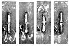
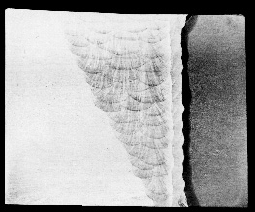
Among the various fracture tests developed by Pellini [PEL 71], we will consider the drop weight test, which consists of dropping a mass from a given height on a specimen comprising a notched brittle weld deposit (see Figure 7.4). The specimen is subjected to bending and its deformation is limited. Under the effect of the shock the bead breaks, which creates a fine crack crossing the heat affected zone (HAZ). Depending on the temperature at which the test is carried out, the crack spreads to a greater or lesser extent in the base metal. We can, by a framework, determine the highest temperature leading to the fracture of the test specimen (see Figure 7.5). This temperature is called the NDT (nil ductility transition). With the original aim of forming steel for ship hulls and submarines, it was then applied to steels for vessels in nuclear installations. The standard defining the Pellini test underwent modifications with regard to the method of bead deposit [AST 95].

As for the Charpy test, studies have been carried out in order to record the load evolution during the impact [SAN 69], thereby to allow a finer analysis of the different fracture phases [FRO 82, WIE 99].
By the early 1970s IRSID had undertaken a systematic comparison between the results obtained from the various tests, considering a wide range of steel types. Correlations were established, showing that the classification of steels is modified little by the choice of tests [SAN 70, SAN 74]. Thus, between temperature NDT obtained by the Pellini test and the temperature giving an energy of 35 J/cm2 (TK 35), starting from 67 data, the following expression:

is proposed, albeit with a rather low correlation coefficient (0.80).
7.2.2. Determination of a fracture criterion in the elastic linear field
The development of the concepts of fracture mechanics at the beginning of the 1960s in the USA made it possible to take defect dimensions into account in the evaluation of the fracture risks. This was achieved by introducing the concept of stress intensity factor KI through the formula:

where α is the coefficient dependant on the geometry of the part and the crack, σ the nominal stress and a the dimension of the crack.
The break occurs when KI reaches the critical value KIC.
The La-Colle-sur-Loup Summer School of September 1970, which was devoted to the fracture process, marked the nascent interest of various sectors of French industry in this new branch of mechanics. The texts of the conferences gathered by D. François [FRA 72] are still used today as a reference in this field.
The determination of the critical stress intensity factor KIC [AST 97] has been applied in various industrial sectors using high elastic limit steels. In France standard NFA 03-180 [NF 81], intended for iron and steel products, defines the test-specimens, the conditions under which they are taken, the conduct of tests and the analysis of results. To obtain a valid value KIC, various conditions must be fulfilled. In particular, when we are concerned with the extent of the plastic zone, this must be small compared to the dimensions of the test-specimen. As a result, in the case of ductile materials, it necessitates the use of large-sized specimens. Indeed, it is necessary that the thickness B is such that:
R p0.2 being the yield strength of the material.
Strictly speaking, this standard applies only to homogenous steels. However, in the absence of specific documents, it has also been applied to other materials as well as to welded joints.
Among the standardized test-pieces most commonly used, the bend test specimen and the compact tensile (CT) specimen should be mentioned and are illustrated in Figure 7.6. The mechanical notch is prolonged by a fatigue crack in order to obtain as low a radius as possible at the extremity. It is important that the crack has the same length on the two faces of the specimen and is of similar internal configuration.

The critical stress intensity factor KIC applies in the case where the plastic zone at the crack’s extremity is small compared to the structural dimensions and thus applies mainly in the case of materials with low ductility or ductile materials of significant thickness.
Like the impact bending energy, the toughness of materials with a centered cubic structure varies according to temperature. It decreases with a fall in temperature; consequently, for a given defect failure can occur at a lower level of loading.
Much work demonstrates that the load speed of application influences toughness. The curve KIC = f (temperature) is shifted towards the right when the load speed increases, as illustrated in Figure 7.7 (taken from a study of Sanz and Marandet) relating to pressure vessel steel 16 MnNiMo5 [SAN 78].
Finding equivalence between the toughness and impact strength tests
Right from the first tests to determine toughness using the concept of fracture mechanics, correlations have been sought, in particular between the values of KIC and those obtained by means of much less costly impact tests. Many expressions are presented and analyzed in [COL 97, MEE 88, SAN 78].
As example, in the ductile field we can quote the expression of Rolfe and Novak, verified by IRSID on a wide range of steels, up to a yield strength of 1,720 MPa. It takes the form:
with  in mm, KV in J and Re in N/mm2.
Correlations also exist between KIC and impact strength at the lower shelf of the transition zone.
IRSID established two additional types of correlation:
– between the transition temperature defined by the tests of KIC and impact strength,
– between the values of KIC and KV.
By regarding the following temperatures as transition temperatures:
– TKIC = temperature for which KIC = 100 MPa.m1/2,
– TK28 = temperature for which KV = 28 J (KCV = 35 J/cm2),
the following correlation can be established, for steels whose crystallinity at temperature TK28 is always higher than 80-85%:

The relation between KIC and KV obtained for values of KV lower than 80 J is expressed for steel as follows:
with KIC in MPa.m1/2 and KV in J.
From the impact strength curve according to temperature, it is possible to plot curve KIC according to the temperature.
7.2.3. Fracture criteria in the elasto-plastic field
In order to evaluate the fracture risks related to the presence of defects in ductile materials, other criteria have been introduced. Among the most used we can quote: JIC, COD, CTOD, whose definitions are recalled in [FRA 96]. For metallic materials, standards have been established by ASTM and employed by AFNOR in order to define the conditions of taking and dimensioning specimens, the conditions of fatigue pre-cracking, the conduct of tests and the analysis of results. The specimens used are more or less comparable with those used for the determination of the critical stress intensity factor KIC.
Rice’s J-integral
The J-integral, still called Rice’s integral, is a contour integral which makes it possible to extend the concepts of elastic linear fracture mechanics to materials presenting a significant plastic deformation at the crack point. This fracture criterion is widely used in the nuclear field to evaluate the risks of ductile tearing. The test conditions are described in [AST 96, NF 87].
The specimens comprise lateral notches facilitating pre-cracking and possibly a chevron notch to facilitate crack initiation. In the case of CT specimens, the notch opening is measured straight along the loading line. During loading, carried out at constant opening speed, the force corresponding to the opening is recorded. The area under the F-d curve, up to the displacement corresponding to the interruption of the test, corresponds to an energy (see Figure 7.8) and is used to calculate J. At the end of the test, the test-piece is turned blue, by hot oxidation, before being broken. Examining the fracture topography makes it possible to evaluate the stable propagation amplitude Δα. The points J-Δa are transferred to a reference frame (see Figure 7.9). After checking the validity conditions, the line dJ/da is determined by linear regression and the values of J0 and J02 corresponding to the start of ductile fracture.
The method of partial unloadings makes it possible to determine, in theory with only one specimen, the critical displacement JIC which corresponds to the beginning of stable cracking.
Between JIC and KIC a relation exists in the form:
where ν is the Poisson coefficient and E the material’s elasticity modulus.
JIC is expressed in J/m 2 when KIC is expressed in MPa.m1/2.
COD
The concept of COD (crack opening displacement) was developed in Great Britain to answer the in-service security issues of the offshore oil rigs built in the North Sea. The specimens used are comparable with those used in elastic linear fracture mechanics and a fatigue crack is developed.
In the beginning, the test consisted of measuring the opening at the notch bottom, δ, according to the load applied. Bearing in mind the difficulty of taking this measurement, a method consisting of calculating δ, beginning by measuring the crack mouth opening by means of a knife edge extensometer, was proposed. This method is based on the assumption that a rotation center exists and will be difficult to determine. It results in uncertainty as to the value of δ [SAN 78].
Assuming we have the COD, the dimension of the critical defect in a structure can be calculated starting from the expression suggested by F.M. Burdekin:

where 
e is the real deformation undergone by the structure in the vicinity of the defect and eγ the deformation at the yield strength.
IRSID has shown that this method resulted in adopting excessive safety margins.
CTOD
Further development has continued, particularly in Anglo-Saxon countries and Japan, leading to CTOD (crack tip opening displacement) testing. The experimental conditions are defined in [AST 93, JWE 97, NF 87].
The force-opening curve is plotted until the test-specimen fractures or, failing this, it is stopped when beyond the load curve maximum. The curve is exploited in accordance with standard BS 7448 Part 1 [AST 93, NF 87].
According to the nature of the material, various types of curves can be obtained (see Figure 7.10). The plastic component Vp of the total opening V is obtained by tracing a straight line parallel with the linear part of the load curve. This component Vp is signified by VC, VI, VU or Vm according to the characteristic point considered.
Figure 7.10. Various types of recordings variations in force applied according to the notch opening; from [NF 87]
For curves a and b, the force applied increases in a steady way with the opening of the notch mouth, until initiating an abrupt unstable crack propagation, which is not preceded by a stable propagation. The value of δC is given starting from the point of coordinates (FC, VC).
In the three other cases, where the unstable propagation or the maximum force of plastic instability, is preceded by a certain stable propagation, the critical values δU or δm of the CTOD are obtained, respectively starting from the points (FU, VU) or (Vm, Fm).
The existence of a stable crack propagation preceding a possible brutal rupture can be highlighted a posteriori by examining the fracture topography.
In all cases the critical values are calculated by means of the formula:
with:

Y being a function of a/W, a0 the useful overall length of the initial defect, and z the distance between the knife blades and the loading axis in the case of a CT specimen. E, R p0.2 and ν are respectively the elasticity modulus, yield strength and the Poisson coefficient of the material.
7.3. Evaluation of fracture risks in welded joints
The evaluation methods used to characterize welded joints are comparable with those implemented to characterize basic materials, except for the added difficulty taking a sample involved with heterogenities of the weld bead.
7.3.1. Heterogenities of the weld bead
To assemble one or two materials by welding with or without filler (electron beam or laser beam welding for example) is a complex metallurgical operation which engenders many heterogenities:
– chemical, the filler product is often different in composition from that of the materials to be assembled. The dilution effects in the bond zones are an additional factor;
– metallurgical, related to the number of heating and cooling phases depending on the number of passes;
– mechanical, the behavior of the bead being different from that of the base materials. This type of heterogenity is referred to by Anglo-Saxons as mismatching. It is characterized by the relationship M between the yield strength of the fusion zone and the yield strength of the base material:

where σYZ is the yield strength of the HAZ and σYB that of the base metal.
If M >1 the term used is overmatching and, in the contrary case, undermatching:
– geometric; taking into account the joint preparations and the shape of the beads (stress concentrations);
– possible defects; planar or volumetric, internal or emerging surfaces which reduce the effective cross section.
To these heterogenities we can add residual stresses, which are a consequence of the juxtaposition of zones brought up to very different temperatures, metallurgical transformations and restrictions of various significance due to clamping.
7.3.2. Conditions of specimen taking
The transposition of the preceding tests to the welded joints must take account of the zones to characterize: fusion zone or HAZ. Figure 7.11 illustrates the most commonly used conditions of specimen removal to evaluate the fracture sensitivity of the fusion zone. In general, the notch is positioned in the middle of the cord with various possible orientations (see Figure 7.12).
The determination of HAZ toughness is much more problematic, taking into account the geometry of the weld bead. A crack machined parallel to the bead axis encompasses more or less significant proportions of the HAZ, the remainder being made up of the base metal (see Figure 7.13). To mitigate this disadvantage, at least for the laboratories, K or half K-shaped specimens can be taken (see Figure 7.14), which makes it possible to have a crack located entirely in the HAZ.
However, in spite of this method, the HAZ is far from being homogenous, as can be seen for example in the work of Toyoda [TOY 91]. It is made up of more or less brittle microstructures which are formed at the time of the various thermal cycles (see Figure 7.15) as will be observed later on (see section 7.4.4).
Figure 7.15. Various types of microstructures found in the HAZ according to the thermal cycles; from [TOY 89]
In certain cases, the test is carried out on a welded sheet 200 mm wide or more, a fatigue crack being developed either in the bead or in the HAZ [KOC 00]. Such test-specimens are in particular used within the framework of the Brite-Euram project ASsessment of quality off POwer beam Welded joints (ASPOW). This project aims at establishing recommendations for the characterization of the joints welded by the processes with high density of energy (electron beam and laser beam) which present a narrow bead with significant property gradients: overmatching for structural steels and undermatching for aluminum alloys.
7.3.3. Determination of the ductile-brittle transition temperature
Concerning the determination of the energy in impact bend tests, standard NF IN 10045-1 [NF 90] defines dimensions and the conditions of sample taking (notch position compared to the FZ or the HAZ). In general, as for the characterization of basic material, the impact bend-test specimen is a parallelepipedic bar (55 × 10 × 10 mm3) with a 45° V-shaped notch 2 mm in depth. The standard envisages the possibility of using test specimens of reduced thickness (7.5 mm or 5 mm).
Following the failures which have occurred during the Kobe and Northbridge earthquakes, impact bend test results showed fracture energies of approximately 10 J at room temperature, for the base metal and the fusion zone, which is very low [TOY 00]. Of the rare plates from Liberty ships which have been examined, energies from 8 to 9 J for the temperature at the time of the accident have been found, whereas energy reached 21 J in the remoter zones [SAN 74].
In general, it is necessary that the ductile-brittle transition temperature is lower than the minimum service temperature. Following the work of a group of experts, made up from members of Commission X of the IIW, chaired by H.H. Campbell, recommendations were made for the mechanized welded constructions erected in zones where seismic risks exist [CAM 00]. The simplest procedure gives, for various risk levels, the impact bend energy values to be reached at a temperature corresponding to the minimum temperature of use (see Table 7.1).
According to the specimen taking conditions and the position of the notch bottom in relation to the FZ or the HAZ, the results can vary significantly, as some of the impact bend test results obtained at various temperatures by N. Gubeljak [GUB 99] show.
Table 7.1. Risk evaluation as a function of the impact strength level; from [CAM 00]
| KV (J) Test temperature = Min. service temperature | Risk of brittle fracture |
| KV>100 | Breakage improbable |
| 47 <KV <100 | Low risk until rotation factors |
| 27 <KV <47 | High risk |
| 10 <KV<27 | High risk. Need for rigorous countermeasures |
| KV <10 | Extremely high risk. Structural insulation essential |
In his study, Gubeljak used a high yield strength of low alloyed steel for the base metal, of the HT80 type, at the quenched-tempered state, 40 mm in thickness. Three welded joints, of X-shaped preparation, presenting overmatching were evaluated. One of them had a homogenous structure (MF1). The two other welds were carried out with the less resistant filler products at the root. The results of the impact bend tests are given in Figure 7.16.

7.3.4. Various methods of toughness evaluation
The concepts of fracture mechanics also apply to mechanized welded constructions, making it possible to evaluate the risks related to the presence of a defect and to judge fitness for use. For that, it is necessary to know the loading conditions, toughness at the crack point as well as the geometry and dimensions of the defect.
The methods determining fracture criteria used for homogenous materials and described in section 7.2 have been transposed to welded joints, in most cases without modification.
Problems involved in pre-cracking
Whatever the method used, it is necessary, initially, to make a fatigue pre-crack. The presence of residual stresses, due to welding, can cause an asymmetric crack front. To mitigate this disadvantage, some studies carry out a stress relief treatment, which modifies the microstructure of the HAZ and the FZ. Dawes, for his part, used a ligament compression procedure in order to redistribute the residual stresses, thus making it possible to obtain a straight crack front [DAW 76].
Critical stress intensity factor KIC
As seen previously, the critical stress intensity factor KIC applies to brittle materials. In the case of welded assemblies, ductile steels are generally used. This criterion can thus only be validated at low temperatures, when the material is in a brittle state.
Fracture in the elasto-plastic field
Under normal service conditions, materials must have, in theory, a ductile behavior. In order to evaluate the rupture risks, related to the presence of a defect, under conditions of a given loading, we use the elasto-plastic rupture criteria (JIC, COD, CTOD).
P. Hornet observed that the J-force curve of a specimen, or structure, with a defect located in the middle of a welded joint, lies between that of an identical base metal specimen and an identical filler metal specimen.
The relative position of the J-force curve depends on the bead width. If it is wide, plastification at the crack point remains confined to the fusion zone and the curve is similar to that of the homogenous filler metal specimen. In the case of a narrow bead, the behavior is dominated by that of the base metal [HOR 00].
This plasticity extension, in heterogenous structures, has consequences for the analysis of the results determining toughness. Various solutions are currently proposed, consisting of measuring toughness on test-specimens with deep cracks (a/W = 0.5) by using the crack mouth opening rather than the displacement of the crack point by applying force. This makes it possible to estimate the quantity of energy applied in the crack zone by not taking account of that dissipated in the base metal.
Any calculation aiming to evaluate the severity of a defect on the fracture risk implies the ability to determine its dimensions.
Taking defects into account
In the case of welded joints, even planar defects have complex geometries. It is also necessary to take the interaction between adjacent defects into account. Methods have been developed to transform these defects into an equivalent 2D geometrical defect (a, b). From this, it is even possible to pass to a 1D parameter of effective size  . Such a step is proposed both for emerging and internal defects [COL 97, HOB 96].
The use of non-destructive testing techniques adapted to the types of defect sought is fundamental. This need for testing should be taken into account right from the design stage, which would prevent many problems once the construction is completed.
Analysis of defect severity
When a defect has been detected in a structural element, three reactions can be considered:
– keep it as it is while continuing to use the material;
– repair it, knowing that a repair can be the origin of another even more severe defect;
– replace the defective part.
Various methods of analyzing defect severity exist to help our decision making, based on existing methods for homogenous structures and adapted in the last few years to welded joints. Amongst the most well known are:
– the modified R6 method (method of two criteria),
– the ETM-MM (Engineering Treatment Model for Mismatched Welds) method,
– the EM (Equivalent Material Method) method,
– the recommendation PD 6493 of the British Standard, entitled: Guidance on methods for assessing the acceptability of flaws in fusion welded structures.
These various methods are presented, for the majority, in [BLA 97].
Recommendation PD 6493 of the British Standard
Recommendation PD 6493, in its last version (June 1991), applies:
– to welded assemblies in aluminum alloys, ferritic and austenitic steels,
– to planar or volumical defects,
– to different modes of failure.
A synthesis of this recommendation, with its advantages and its limitations, as well as an application to fluid conduits, was carried out by R. Batisse [BAT 00].
This recommendation is used for pressure vessels, pipelines, bridges, constructions, storage tanks, naval construction and offshore work, etc.
According to this recommendation, the treatment of acceptability of a defect, in terms of risk of rupture, rests on the FAD (failure assessment diagram) and requires the calculation of two parameters corresponding respectively to the brittle risk of fracture Kr (y-axis) and that of plastic collapse Sr (x-axis).
Various levels of investigation are proposed. Figure 7.17 sets out levels 1 and 2.
Level 1 is the most restrictive. It allows a fast analysis with a minimum of data. It does not require the taking into account of safety factors, those being integrated by an increase of the stresses and dimensions of the defects and a decrease of mechanical properties.
Level 2 admits the possibility of initiation of ductile tearing before failure and takes into account the stresses at the level of the defect. Safety coefficients are applied to the stresses, dimensions of the defect and the mechanical properties.
Level 3 (see Figure 7.18) can be used when the collapse is preceded by a significant plastic deformation.
The point can be placed in the FAD diagram with its position depending on the type of defect (its position and its dimensions) and conditions in use (loading, temperature, etc.). According to its position, inside or outside the diagram, the defect is either acceptable or not.
This recommendation is designed to be simple, capable of meeting industrial needs. However it leads, in a certain number of cases, to results with limited accuracy in relation to certain assumptions such as:
– taking account of residual stresses equal to the elastic limit,
– a K approach, based on linear fracture mechanics, poorly adapted for a crack whose plastification is not confined,
– use of approximate mechanical properties.
The European project SINTAP (Structures INTegrity Assessment Procedures) turned its attention to recommendation PD 6493 with the intention of limiting such results by proposing a certain number of simplified solutions.
7.4. Consequences of heterogenities on the evaluation of fracture risks
The evaluation of fracture risks in welded joints will be a major issue in years to come, as much for new buildings as for those in service. The frequency of maintenance, where cost gains are to be hoped for, and the increase in the lifespan of an installation, are ongoing problems that demand a better knowledge of welded structures.
Welded joints are by nature heterogenous and the probability aspects must be taken into account.
7.4.1. Mismatching effects
In 1993, at the annual meeting of the IIW, it was decided to establish Sub-Commission X F within Commission X, specifically instructed to take mismatching effects into account. Bearing in mind the multi-disciplinary nature of the problem, this group involved specialists working in several different areas. In seven years, nearly 100 documents, whose list appears in the President’s Report [KOC 00], were presented and made the subject of debate. Among the topics discussed were:
– taking mismatching into account in processes with high energy density,
– mismatching occurring during friction welding (stir friction),
– consequences of mismatching during seismic loadings,
– mismatching related to a coating or a recoating.
Currently, the codes do not take mismatching into account. They consider a homogenous material, which has the most disadvantageous characteristics among those involved in welding. Generally, this leads to conservative results.
Two programs of the European Community particularly take the effects of mismatching into account. In addition to the now deceased SINTAP program, the ASPOW program (ASsessment of quality of POwer beam Welded joints) deals with the characterization of joints welded by beams with high density of energy. The applications relate in particular to the use of laser welding of aluminum alloys in aeronautics, within the framework of the Airbus 380 program.
The laboratory tests carried out on welded test-specimens with a defect located in the fusion zone highlight the influence of:
– mismatching,
– dimensions of the HAZ in relation to those of the test-specimen,
– load pattern (tension or bending),
– position of the crack point’s extremity compared to the bead,
– evolution of plasticity in the ligament.
In France, many studies have been undertaken to counter the problems presented in the nuclear field. Hornet [HOR 00] showed that in the case of overmatching, plasticity develops mainly in the softest metal, except if the FZ is rather wide, in which case plasticity is confined there (see Figure 7.19).
On the other hand, for narrow beads, the overall behavior of the heterogenous structure seems little influenced by the existence of the FZ, whatever the crack length. Behavior in the vicinity of the crack, like that of the structure as a whole, seems controlled by the base metal. The plasticization, originating at the crack point in the melted zone, joins the bond zone to develop then in the base metal (see Figure 7.19). The mushroom shaped plastic zone, characteristic of overmatching, extends in the base metal which governs the crack loading.
Hornet also shows that if the ratio h/(W-a) is high, the mechanical strength of the structure is controlled by the molten metal, whereas if it is close to 0, it is controlled by the base material.
The loading conditions (tension or bending) also influence the development of plasticity and the possibility of the plastified zone leaving the added metal. According to Hornet, a bending load favors the containment of plasticity in the molten metal (see Figure 7.20) more than a tensile load.
Similar results are found in the part of the ASPOW project devoted to the characterization of welded joints, made by laser or electron beam, for steels of various strength levels, where the degree of overmatching is important. It was shown that a crack, started in the bead, quickly changes orientation to develop in the more ductile base metal, this phenomenon holding good both for test-specimens comprising wide plates or traditional fracture test pieces, CT type or thin bending specimens. If the thickness B of the test-specimens increases, the crack remains in the melted zone, which results in a reduction of CTOD [KOC 99]. The fact that the crack moves towards the most ductile zone is reassuring for those processes with high energy density.

The consequences of mismatching on the CTOD were studied for various materials: aluminum alloys presenting undermatching, austenitic stainless steels, Inconel 625 nickel alloys, and titanium alloys.
For the latter, we cite the work of M. Koçak who, while during diffusion welding of titanium and a TA6V titanium alloy, produced either an undermatching equal to 0.36 (TA6V/Ti/TA6V) or an overmatching of 2.5 (Ti/TA6V/Ti) with variable widths and perfectly straight bond zones. In the first case, the crack remains in the most ductile zone and the plastified zone remains confined; in the second case, the crack deviates towards the most ductile material or propagates to the level of the interface.
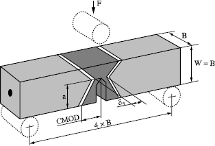
N. Gubeljak studied, in the case of an X-shaped preparation, the influence of the crack tip’s position on the toughness expressed in terms of CTOD (see Figure 7.21). When the a/W ratio increases, the width of the molten zone decreases and reaches a minimum at the level of the root. Constriction effects the development of the plastified zone at the crack tip and thus on the results, which present dispersions. To mitigate this weakness, corrective formulae are proposed [GUB 99].
Figure 7.21. Influence of geometry of the molten zone and position of the bottom of the fatigue crack on the determination of the CTOD; from [GUB 99]
7.4.2. Influence of the base material
Manufacturing conditions
The base material, used for the realization of mechanized welded constructions, must have a ductile-brittle transition temperature lower than the minimum temperature of in-service use. At the beginning of the 1970s, French standard NF A 36-201 defined three levels of quality (R, C and FP) for non-alloyed sheet steels or low alloyed weldable steels (E 355, E 375, E 420 and E 460) guaranteeing minimal impact strength values in more or less low temperatures according to the conditions of use.
In order to provide users with steels that were easier to weld, while being more resistant and tougher, steel manufacturers lowered the percentage of carbon (reduction in equivalent carbon (Ceq), which leads to a lowering of TK 28 (see Figure 7.22). Further developments also made it possible to improve the product quality by reducing the impurity content (sulfur, phosphorus) or trace elements (arsenic, antimony, tin). These reductions have made it possible to lower the transition temperature in the affected zone of Cr-Mo steels sensitive to the phenomenon of reversible embrittlement.
Vacuum processes, such as dehydrogenation, made it possible to reduce the hydrogen content to less than 2 ppm, in particular in steels for heavy plates. In addition, it was possible to obtain a low nitrogen content by calling upon techniques that avoid molten steel and ambient air during casting.
For the same sulfur content, the morphology of sulfides plays a big role in impact strength through the thickness. The addition of cerium or calcium appreciably improves impact strength by the formation of globulized sulfides (see Figure 7.23).
Thermomechanical treatments
Thermomechanical rolling, followed by an accelerated cooling, led to the development of high yield strength (HYS) steels. The decreased percentage of carbon was compensated for by a refinement of the grain size and by the precipitation of dispersoid elements which allow hardening the ferritic phase [DEF 94]. This generates an increase in strength and yield strength while lowering the transition temperature.
Figure 7.23. Impact strength through the thickness. Influence of sulfur content and sulfide morphology; from [DEV 88]
In a paper, Bourges et al. [BOU 97] showed that for a steel supplied according to the same designation, the manufacturing conditions can have an important role on the condition of use. Thus steel-killing with aluminum, without silicon, had a beneficial effect, making it possible to limit the sensitivity to ageing after work hardening by bending (see Figure 7.24).
In steels with 0.080% C, 1.5% Mn and 0.5% Ni, the influence of silicon content also occurs on the temperature TK28 in the HAZ, in a way all the more marked when the cooling speed during welding is slower, which is the case for the processes with high density of energy (see Figure 7.25). The reduction of silicon content makes it possible to decrease the fraction of residual austenite in the HAZ, which improves toughness in this zone.
Figure 7.24. Evolution of the TK35 level in relation to deformation and steel-killing; from [BOU 97]
Figure 7.25. Influence of the Si content and cooling speed in the HAZ on impact strength; from [BOU 97]
7.4.3. Influence of filler metals
An assessment of progress made, in terms of filler materials, was presented by Bourges et al. [BOU 98]. A comparison is made between basic and rutile filled wires. The basic wires have the greatest potential because of their chemical composition, and make it possible to obtain a high ductile level in impact strength as well as a good toughness at low temperature. However, the basic wires have inferior operational characteristics to those of rutile wires.
Significant improvements have been made to rutile wire, which uses the titanium/boron effect by selecting the raw materials in a rigorous way, in order to limit the impurities and carbide-forming elements responsible for a decrease in toughness after stress relief treatments. It should also be added that some wires have a diffusible hydrogen rate sufficiently low to be classified in the H5 category (lower than 5 ml/100 g of added metal). These various aspects are detailed by Bonnet (see Chapters 4 and 5 of this book).
7.4.4. Importance of welding conditions
In the case of multipass welding, each pass is at the origin of microstructural transformations which vary according to the maximum temperature reached. Thus, the HAZ comprises local brittle zones (LBZ) as stated by [DEF 94]. The complexity of the HAZ is schematized in Figure 7.15.
The research undertaken during recent years has underlined the role of certain microstructural components, composed of martensite and residual austenite (M-A compounds), on toughness. The morphology of these compounds acts on impact strength. It was shown that it is especially large M-A compounds (higher than 2 µm) and/or solid masses (shape factor less than 4) which involve a decrease in impact strength. These compounds constitute the local embrittlement zones.
Figure 7.26 makes it qualitatively possible to judge the influence of the total local brittle zone on the COD. The LBZ is the sum of:
– the reheated coarse grain zone in the subcritical field,
– the reheated coarse grain zone in the intercritical field,
– the non-transformed coarse grain zone.
At the beginning of the 1990s, Kaplan developed a software simulation, called Multipasses, which makes it possible to evaluate, in the case of C-Mn steels, depending on the composition of the base steel, the filler and the welding parameters (voltage, intensity, speed, efficiency coefficient, pre-heating temperature and interpass temperature), the proportions of LBZ which directly influence toughness. Such predictive tools are an aid for both steelmakers and welders [DEV 94].
Figure 7.26. Relation between the COD and the proportion of LBZ intercepted by the fatigue crack; from [AIH 88]
7.4.5. Evaluation and taking account of residual stresses
The welding operations and its related techniques comprise rapid phases of heating and cooling which entail deformations and the creation of residual stresses. In the absence of precise data, it is useful to consider that their level is equal to the elastic limit of the material, which in the majority of the cases is disadvantageous if we refer to the results obtained by simulation.
Modeling and simulation in this field began in France in the 1980s with the development of the software SYSWELD, by Devaux and Leblond. They based their ideas, with regard to the metallurgical transformations, on the work of R. Blondeau [BLO 75] and that of A. Simon’s team, a short summary of which is given in [SIM 93].
This software makes it possible to simulate welding while taking thermal, metallurgical and mechanical aspects into account and working by sequential analysis. Starting from the welding parameters, thermo-metallurgical calculation makes it possible to obtain the temperatures and phases formed at any point according to time. This stage takes into account the variations of thermal conductivity, specific heat and volumic mass according to the temperature.
There follows the mechanical calculation, thermo-elastoplastic in nature and requiring us to take into account various phenomena related to metallurgical transformations. The mechanical characteristics depend on the phase proportions. It is necessary to take the variations of volume and the plasticity transformation into account. Digital simulation requires that we have a great deal of data relative to the materials, which is available for only a few steel types.
Figure 7.27 gives an example evaluation of longitudinal and circumferential residual stresses obtained by an EB capacitive pressure weld in 10CrMo9-10 steel. We should note the presence of compressive stresses on the surface in the vicinity of the bead toe and internal tensile stresses. On both sides of the bead, there are on the surface tensile stresses. Qualitatively the stress distribution had been confirmed by X-ray diffraction and the hole drilling method (see Figure 7.28). Quantitatively, the differences between calculation and experimental methods were considerable and were explained by a 2D analysis [DEV 89].
Simulation makes it possible to obtain information otherwise inaccessible by traditional experimental techniques.
This data, and in particular the transverse residual stresses in thickness, were taken into account by A. Carmet to evaluate dimensions of the allowable defects by using various fracture criteria. This step made it possible to decrease, in the majority of cases, the severity of the various rules of acceptance [CAR 90].

Burdekin gathered together exercises dealing with fracture risk evaluation of welded joints by taking account of residual stresses [BUR 96].
Examples of residual stress distribution, for various joint types, exist in the literature. Since 1996, under the initiative of Janosch, a working group has been constituted from members of Commissions X and XV of the IIW, facilitating a considerable exchange of ideas. The titles of the documents presented since 1997 are gathered in [JAN 00].
A round-robin gathering together ten teams undertook the simulation of a circumferential joint for tube welding. The first results show that, according to the methods used, important variations can be observed even in thermal analysis at a given point. The aim of this work is to make recommendations on implementation methods in order to obtain more coherent results [KOP 00].
Within the framework of a co-operative study, teams of the ECA, EDF and Framatome employed different codes (Castem 2000, Aster and Sysweld), to obtain homogenous results with regard to the stress distribution for the multipass welding of a cylinder in austenitic 316L steel. For that purpose, experiments were carried out, with particular regard to thermal cycle analyzing during the various welding passes. Micrographic examination allowed some readjustments. The calculations fit in well with stresses determined by experimental methods [KIC 00].
7.5. Bibliography
[AIH 88] HAZE T., AIHARA S., “Influence of toughness and size of local brittle zone on HAZ toughness of HSLA steels”, Proceedings of the 7th International Conference on Offshore Mechanics and Arctic Engineering, OMAE 1988, ASME, Houston, USA, 1988.
[ANS 92] American National Standards Institute and American Welding Society, Standard methods for mechanical testing of welds, ANSI/AWS B4.0-92, 29 June 1992.
[AST 93] ASTM, Standard test method for crack tip opening displacement (CTOD) fracture toughness measurement, ASTM E 1290-93, 1993.
[AST 95] ASTM, Standard test method for conducting drop-weight test to determine nilductility-transition temperature of ferritic steels, ASTM E208-95a, 1995.
[AST 96] ASTM, Standard test method for J-integral characterization of fracture toughness, ASTM E 1737-96, 1996.
[AST 97] ASTM, Standard test method for plane strain fracture toughness of metallic materials, ASTM E 399-90 (reapproved 1997), 1997.
[BAL 97] BALLADON P., DI FANT M., PONSOT A., “Dureté, résistance et ténacité”, Les aciers spéciaux, Lavoisier, pp. 452-473, Paris, 1997.
[BAT 00] BATISSE R., “Présentation de la recommandation PD 6493. Application aux conduites de transport de fluides”, Séminaire sur la prévention de la rupture dans des joints soudés, Institut de Soudure, 9 March 2000.
[BLA 96] BLAUEL J.G., BURDEKIN F.M., “Case study collection on the assessment of the significance of weld imperfections”, Welding in the World, 37, no. 4, pp. 194-216, 1996.
[BLA 97] BLAUEL J.G., Failure assessment concepts and applications, Doc. IIS — IIW X1407-97, 1997.
[BLO 75] BLONDEAU R., MAYNIER PH., DOLLET J., VIEILLARD-BARON B. “Prévision de la dureté, de la résistance et de la limite d’élasticité des aciers au carbone et faiblement alliés d’après leur composition et leur traitement thermique”, Mém. Scient. Rev. Métall. pp. 759-769, November 1975.
[BON 97] BONNEFOIS B., BOURGES P., MABELLY P., DEBIEZ S., BONNET C., ROUAULT P., MAGOARIEC A., TAILLARD R., KAPLAN. D. et al., Quelques développements récents permettant une amélioration supplémentaire de la qualité des structures d’aciers soudées, Doc. IIS/IIW IX-1886-97, 1997.
[BON 98] BONNEFOIS B., BOURGES P., MABELLY P., DEBIEZ S., BONNET C., ROUAULT P., MAGOARIEC A., TAILLARD R., KAPLAN. D. et al., “Une amélioration supplémentaire de la qualité des structures soudées en acier”, Soudage et Techniques Connexes, vol. 52, no. 1/2, January/February 1998.
[BUR 92] BURDEKIN F.M., “Choix des aciers pour les constructions soudées”, Soudage et Techniques Connexes, vol. 46, no. 11/12, November/December 1992.
[BUR 96] BLAUEL J.G., BURDEKIN F.M., “Case study collection on the assessment of the significance of weld imperfections”, Welding in the World, 37, no. 4, pp. 194-216, 1996.
[CAM 00] CAMPBELL H.H., Status of the IIW recommendations on fracture control in seismically affected steel structures, Doc. IIS/IIW X-1456-00, 2000.
[CAR 90] CARMET A., SOCQUET J., “Influence des contraintes résiduelles de soudage sur les conditions de rupture d’appareils à pression”, Soudage et Techniques Connexes, vol. 4, no. 11/12, November/December 1990.
[CHE 70] CHEVIET A., GRUMBACH M., PRUDHOMME M., SANZ G., “Comparaison des résultats de divers essais de rupture fragile”, Revue de Métallurgie, pp. 217-236, March 1970.
[COL 97] COLLECTIF, Method of assessment for flaws in fusion welded joints with respect of brittle fracture and fatigue crack growth, Doc. IIS/IIW X-1428-98, 1997.
[DAW 76] DAWES M.G., “Contemporary measurements of weld metal fracture toughness”, Welding Journal, pp. 1052-1057, December 1976.
[DEF 94] DEFOURNY J., “Soudabilité des aciers produits par laminage thermomécanique ou par refroidissement accéléré”, Soudage et Techniques Connexes, vol. 48, no. 7/8. July/August 1994.
[DEV 89] DEVAUX J.C., CARMET A., LEBLOND J.B., “Détermination numérique des contraintes et des déformations résiduelles dans un joint soudé par faisceau d’électrons”, Soudage et Techniques Connexes, vol. 48, no. 9/10, September/October 1989.
[DEV 94] DEVILLERS L., KAPLAN D., TESTARD P., “Prévision des microstructures et de la ténacité des ZAT de soudures”, Soudage et Techniques Connexes, vol. 48, no. 7/8, July/August 1994.
[FOR 00] FORGET P., “Modélisation de la rupture des liaisons soudées bimétalliques”, Séminaire sur la prévention de la rupture dans des joints soudés, Institut de Soudure, 9 March 2000.
[FRA 72] FRANÇOIS D., JOLY.L., La Rupture des Métaux. Ecole d’été de la Colle sur Loup, September 1970, Masson, 1972.
[FRA 92] FRANÇOIS D., Provisional definitive statement of significance of local brittle zones, Doc IIS-IIW X-1246-92, 1992.
[FRA 96] FRANÇOIS D., “Guidelines for terminology and nomenclature in the field of structural integrity”, Fatigue & Fracture of Engineering Materials & Structures, vol. 19, no. 12, pp. 1515-1533, 1996.
[FRA 00] FRANÇOIS D., “Aspects probabilistes de la rupture des joints soudés”, Séminaire sur la prévention de la rupture dans des joints soudés, Institut de Soudure, 9 March 2000.
[FRO 82] FROMM K., SCHULZE H.D., Pellini’s theory of brittle fracture and the limits of its applicability, Doc IIS — IIW 1011 — 82, 1982.
[GRU 69] GRUMBACH M., PRUDHOMME M., SANZ G., “Essais dynamiques de rupture fragile avec enregistrement”, Revue de Métallurgie, pp. 271-281, April 1969.
[GUB 99] GUBELJAK N., “Estimation de la ténacité minimale s’assemblages soudés affectés d’une hétérogénéité mécanique (mismatch)”, Soudage et Techniques Connexes, vol. 53- no. 7/8, July/August 1999.
[HOB 96] HOBBACHER A., Recommandations pour la conception en fatigue des assemblages et composants soudés, Document IIS-IIW XIII-1539-96/ XV-845-96, 1996 (version française, publication CTICM, October 2000).
[HOR 00] HORNET P., “Prise en compte de l’effet mismatch dans le comportement mécanique des structures soudées fissurées”, Séminaire sur la prévention de la rupture dans des joints soudés, Institut de Soudure, 9 March 2000.
[JAN 00] JANOSCH J.-J., GORDON R., Residual stress and distortion prediction in welded structures, 4th annual report, Doc. IIS — IIW X-1455-00, 2000.
[KAL 00] KALNA K., Design of steels structures against brittle failure in different European standards, Doc. IIS/IIW X-1465-00, 2000.
[KIC 00] KIHENIN J., RAZAKANAIVO A., DESROCHES X., BOIS C., LEJEAIL Y., Tubular welding numerical simulation: Experimental validation, Doc. IIS/IIW X/XV-RSDP-56-00, 2000.
[KIM 98] KIM Y.J., “Effets d’une hétérogénéité mécanique (mismatch) sur les contraintes locales”, Soudage et Techniques Connexes, vol. 52, no. 3/4, March/April 1998.
[KOC 99a] KOÇAK M. et al., “Recommendations on tensile and fracture toughness testing procedures for power beam welds”, European Symposium on Assessment of Power Beam Welds, 4-5 February 1999, Doc IIS — IIW X-1445-99, 1999.
[KOC 99b] KOÇAK M., THAULOW C., “Special issue on strength of mismatched welded joints”, Engineering Fracture Mechanics, vol. 64, no. 4, November 1999.
[KOC 00] KOÇAK M., DOS SANTOS J.F., “Le soudage et l’assemblage au XXIe siècle: Soudage laser: tendances dans les applications industrielles et dans l’évaluation de la qualité”, Soudage et Techniques Connexes, vol. 54, no. 5/6, May/June 2000.
[KOC 00] KOÇAK M., 7th Annual Report of Sub-Commission X-F Weld Mis-Match Effect, Doc. IIS/IIW X-1457-00, 2000.
[KOL 00] KOPPENHOEFER K., GORDON R., IIW Round Robin on residual stress and distortion prediction. Phase 1 results, Doc IIW X/XV-RDSP-55-00, 2000.
[KON 94] KONECZNY H., “De l’utilité des calculs de mécanique de la rupture”, Soudage et Techniques Connexes, vol. 48, no. 7/8, July/August 1994.
[KON 00] KONECZNY H., JANOSCH J-J., DEBIEZ S., “Définition d’une base de données matériaux pour les constructions soudées lourdes par caractérisation expérimentale de ténacité/résilience”, Revue Française de Mécanique, no. 1997-1, pp. 17-25, 2000.
[LAF 88] LAFRANCE M., POUPON M., DEVILLERS L., “Les outils et technologies modernes de production des aciers”, Soudage et Techniques Connexes, vol. 47, no. 11/12, November/December 1988.
[LEI 62] DE LEIRIS H., BONIZEC R., “L’essai au mouton Pellini et les assemblages soudés”, ATMA 1961, pp. 669-684, 1962.
[LEI 71] DE LEIRIS H., Métaux et alliages, Tome I, Cours ENSTA, Masson & Cie, 1971.
[LEI 96] LEI W., YAO M., “The physical nature of drop weight test NDT”, Engineering Fracture Mechanics, vol. 53, no. 4, pp. 645-652, 1996.
[MEE 88] MEESTER DE B., “Choix des aciers selon leurs propriétés Charpy V en vue d’éviter la rupture fragile”, Le Soudage dans le Monde, vol. 26, no. 11/12, 1988.
[MUH 98] MUHAMMED A., The effect of prior overload and its application in structural integrity assessments, SINTAP/TWI/014, TWI Report no. 88269/1/98, March 1998.
[NF 81] NORME FRANÇAISE, Produits sidérurgiques. Détermination du facteur d’intensité de contrainte critique des aciers, NFA 03 180, June 1981.
[NF 84] NORME FRANÇAISE, Assemblages plans et tubulaires soudés bout à bout — Essai de flexion par choc sur éprouvette bi-appuyée (entaille en V), NF A 89-202, July 1984.
[NF 87a] NORME FRANÇAISE, Produits sidérurgiques — Mécanique de la rupture — Détermination de l’écartement à fond de fissure (CTOD), NF A 03 182, June 1987.
[NF 87b] NORME FRANÇAISE, Produits sidérurgiques — Mécanique de la rupture — Détermination à partir de la courbe J-δa des valeurs conventionnelles J0 et DJ/DA- Caractéristique de la résistance à la déchirure ductile, NF A 03 183, June 1987.
[NF 90] NORME FRANÇAISE, Matériaux métalliques — Essai de flexion par choc sur éprouvettes Charpy — Partie 1: Méthode d’essai, NF EN 10045-1, October 1990.
[PEL 71a] PELLINI W.S., “Principles of fracture safe design — part I”, Welding Research Supplement, pp. 91-109, March 1971.
[PEL 71b] PELLINI W.S., “Principles of fracture safe design — part II”, Welding Research Supplement, pp. 147-162, April 1971.
[ROS 98] ROSSOL A., Détermination de la ténacité d’un acier faiblement allié à partir de l’essai Charpy instrumenté, PhD Thesis, ECP 98-43, 1998.
[SAN 74] SANZ G., La rupture des aciers. La rupture fragile 1, Collection IRSID OTUA, 1974.
[SAN 78] SANZ G., La rupture des aciers. La mécanique de la rupture 2, Collection IRSID OTUA, 1978.
[SIM 93] SIMON A., DENIS S., “Modélisation et calcul des transformations de phases et des contraintes internes en traitement thermique des aciers”, Les Entretiens de la Technologie, 11 May 1993, Nantes, Atelier Matériaux 6: Transformations microstructurales, 1993.
[SOU 97] SOULIGNAC P., BERANGER G., HENRY G., LABBE G., Les aciers spéciaux, Lavoisier, Paris, 1997.
[TOY 89] TOYODA M., “Fracture toughness evaluation of steel welds”, Review Part II, University of Osaka, 1989.
[TOY 91] TOYODA M., Recommendation for understanding the significance of CTOD test, results for steel weld HAZ, IIS — IIW Commission X, 1991.
[TOY 00] TOYODA M. et al., Fracture mechanics approach for fracture performance evaluation of steel structures under seismic loading, Doc IIS — IIW X-1462-00, 2000.
[WIE 99] WIESNER C.S., SMITH S.D., Pellini drop-weight testing to charaterise structural crack arrest behaviour, Doc IIS — IIW X-1438-99, 1999.
[WIL 99] WILSIUS J., IMAD A., NAIT ABDELAZIZ M., MESMACQUE G., ERIPRET C., “Analyse des modèles basés sur l’approche locale en mécanique de la rupture”, Soudage et Techniques Connexes, vol. 53, no. 11/12, November/December 1999.
[WIL 99] WILSIUS J., Etude expérimentale et numérique de la déchirure ductile basée sur des approches locales en mécanique de la rupture, PhD Thesis, Université des Sciences et Technologies de Lille, December 1999.
[XU 97] XU W.G., “Diagrammes d’évaluation de la rupture en présence de contraintes résiduelles”, Soudage et Techniques Connexes, vol. 51, no. 11/12, November/December 1997.
1 Chapter written by Marc BOUSSEAU.