Chapter 11. Motherboards and Add-on Cards
This chapter covers a portion of the following A+ 220-1001 exam objective:
• 3.5 – Given a scenario, install and configure motherboards, CPUs, and add-on cards.
Note
Objective 3.5 covers a lot. That’s why I broke it up into two chapters. This chapter covers motherboards and add-on cards. The next chapter will cover CPUs.
Without a doubt, the motherboard is the foundation of the computer. Everything connects to the motherboard and all data is transferred through this matrix of circuitry.
Over the years I have found that if a student is going to lack knowledge in one area, it’s quite often going to be the motherboard. Unfortunately, this is one of the key elements in a computer system. It’s the starting point for a quick and efficient computer. Because it connects to everything in the computer system, you need to know many concepts concerning it. Let’s get right into it.
3.5 – Given a scenario, install and configure motherboards, CPUs, and add-on cards.
ExamAlert
This portion of Objective 3.5 concentrates on the following concepts: motherboard form factors and connector types; BIOS/UEFI settings; CMOS battery; and expansion cards.
Motherboard Form Factors & Connectors
A computer form factor specifies the physical dimensions of some of the components of a computer system. It pertains mainly to the motherboard but also specifies compatibility with the computer case and power supply. The form factor defines the size and layout of components on the motherboard. It also specifies the power outputs from the power supply to the motherboard. The most common form factors—and the ones you need to know for the exam—are ATX, microATX, and Mini-ITX. Let’s discuss these a little further now.
ATX
Advanced Technology Extended (ATX) was originally designed by Intel in the mid-’90s to overcome the limitations of the now-deprecated AT form factor. It has been the standard ever since. The motherboard shown in Figure 11.1 is ATX. This is the board used in the AV-Editor computer, which is my main workstation. Full-size ATX motherboards measure 12 inches × 9.6 inches (305 mm × 244 mm). ATX motherboards have an integrated port cluster and normally ship with an I/O plate that snaps into the back of the case, filling the gaps between ports and keeping airflow to a minimum.
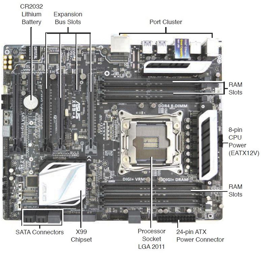
Figure 11.1 ATX Motherboard and its Components
One identifying characteristic of ATX is that the RAM slots and expansion bus slots are perpendicular to each other. The ATX specification calls for the power supply to produce +3.3 V, +5 V, +12 V, and −12 V outputs and a 5 V standby output. These are known as “rails” (for example, the +12 V rail). The original ATX specification calls for a 20-pin power connector (often referred to as P1); the newer (and much more common) ATX12V Version 2.x specification calls for a 24-pin power connector. You can test these voltages with a power supply tester which typically comes with a 24-pin input as well as other inputs for SATA power, PCI Express 6 and 8-pin and Molex.
ExamAlert
Know the voltages supplied to an ATX motherboard by a power supply: +3.3 V, +5 V, +12 V, −12 V outputs and +5 V standby output.
An ATX motherboard is attached to the computer case with several screws. Before you screw it in though, attach the I/O plate to the back of the case, and dry fit the motherboard to see where the screws will attach to the case. Apply rubber standoffs if required. Then, attach the accepting screws to the case wall according to where the motherboard screws will be placed; be sure that the motherboard will be properly supported. Angle the motherboard slightly so that the port cluster fits into the I/O plate. Then line up the screw holes and attach the screws. Finally, connect the CPU, RAM, power connections, adapter cards, fans, and anything else necessary!
microATX
microATX (or mATX) was introduced as a smaller version of ATX; these motherboards can be a maximum size of 9.6 inches × 9.6 inches (244 mm × 244 mm) but can be as small as 6.75 inches × 6.75 inches (171.45 mm × 171.45 mm). In comparison, microATX boards are usually square, whereas full-size ATX boards are rectangular. microATX is backward compatible with ATX, meaning that most microATX boards can be installed within an ATX form-factor case and they use the same power connectors as ATX. Often, they have the same chipsets as ATX as well. microATX works well for desktop cases, small rackmount servers and home theater PCs (HTPCs).
Mini-ITX
ITX is a group of form factors developed by VIA Technologies, Inc., between 2001 and now for use in small, low-power motherboards. The ITX group includes Mini-ITX, Nano-ITX, Pico-ITX, and Mobile-ITX, but Mini-ITX (mITX) is what is covered in the A+ objectives.
Originally designed in 2001, Mini-ITX is a 6.7 × 6.7-inch (17 × 17 cm) motherboard that is a bit smaller than microATX and is screw-compatible, enabling it to be used in microATX and ATX cases if so desired. The original version used passive cooling to keep it quiet and to conserve power, making it ideal for HTPCs; newer versions use active cooling due to the more powerful processors involved. The first version of these boards came with one expansion slot: PCI. The second version comes with a single PCIe x16 slot.
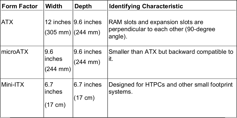
Table 11.1 compares the ATX, microATX, and Mini-ITX form factors, supplying the sizes of these motherboards and some of the characteristics that set them apart.
Table 11.1 Comparison of Motherboard Form Factors
ExamAlert
Know the basics of ATX, microATX, ITX, and Mini-ITX for the exam.
Expansion Buses
There are two main expansion buses and their corresponding adapter card slots that you need to know for the exam. They include PCI Express and PCI:
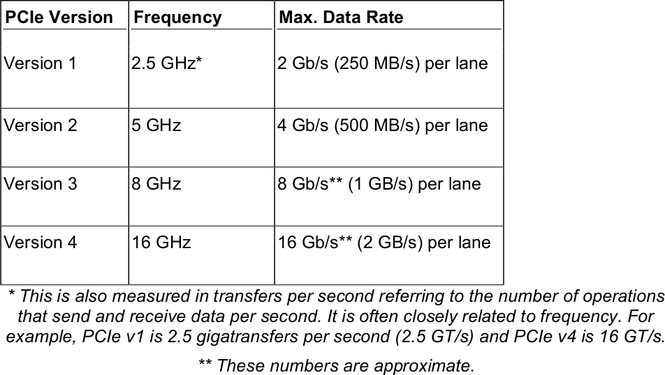
• PCI Express (PCIe): Currently the king of expansion buses, PCIe is the high-speed serial replacement of the older parallel PCI standard and the deprecated AGP standard. The most powerful PCIe slots—such as x16—connect directly to the processor (or northbridge). The lesser PCIe slots—such as x1—connect to the chipset. The PCIe expansion bus sends and receives data within lanes. These lanes are full-duplex, meaning they can send and receive data simultaneously. There are several versions of PCIe—their data rates are shown in Table 11.2. Commonly, PCIe video cards are x16 (pronounced “by 16”), which means they use 16 lanes, and usually require version 3 minimum. They can typically transfer 16 GB/s—in each direction. Most other PCIe adapter cards are x1, but you might find some x4 cards as well. Of course, compatibility is key. A x1 card can go in a x1 slot or larger, but a x16 card will fit only in a x16 slot, nothing smaller. Figure 11.2 displays three x16 slots and one x1 slot.
Table 11.2 Comparison of PCIe Versions and Data Transfer Rates
Note
Maximum data transfer rates are never attained, even in a lab environment. You can expect actual throughput to be substantially lower, but professionals use the maximum data rate as a point of reference and as a way of comparison.
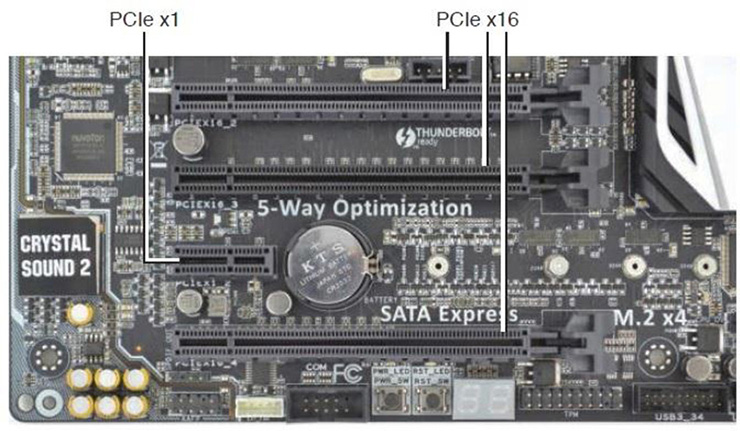
Figure 11.2 PCIe x16 and PCIe x1
ExamAlert
Identify the PCIe x16 and x1 expansion slots for the exam.
• PCI: The Peripheral Component Interconnect bus was developed in the’90s by Intel as a faster, more compatible alternative to the deprecated ISA bus. It allows for connections to modems and to video, sound, and network adapters. This uncommon bus connects exclusively to chipset (or southbridge). Because of this, other high-speed video alternatives were developed that could connect directly to the processor (or northbridge). PCI version 2.1 cards are rated at 66 MHz, and their corresponding PCI bus is 32-bits wide, allowing for a maximum data transfer rate of 266 MB/s. Derivatives of PCI include PCI-X, which was designed for servers using a 64-bit bus and rated for 133 MHz/266 MHz, and Mini PCI, which is used by laptops. PCI slots are seldom found on today’s motherboards. For the most part, they have been overtaken by PCIe technology.
Note
I’ve mentioned the chipset several times. The chipset connects all of the motherboard’s secondary device interfaces together; such as USB, SATA 3.0, the network card, and more. The chipset then connects to the CPU which has connections to the primary devices (RAM and video card). The motherboard displayed in Figure 11.1 uses the X99 chipset. To see a diagram of this chipset, and all of its connections, use the following link or search the Internet for “Intel X99 chipset diagram.”
https://www.intel.com/content/www/us/en/chipsets/performance-chipsets/x99-chipset-diagram.html
Expansion Cards
If a motherboard does not have a necessary integrated component, you will have to add an expansion card to a PCIe slot. During the planning stage you should make sure one is available, and then determine the requirements of the card: version of PCIe, bus width, and so on. There are plenty of different expansion cards that you might add, but the most common is probably the video card. Some computers come with integrated video cards (also known as on-board). In some cases, these utilize powerful processing that is built into the board (some AMD systems have this), but many times the integrated video card is designed for basic computing and does not perform well enough for any high-end computing. So, an actual video card is often necessary.
Installing Video Cards
Today’s video cards are like little self-contained computers! They have a processor, known as a graphics processing unit (GPU), and a substantial amount of RAM. When choosing a video card, there are several things to consider, including the expansion bus that the card connects to, the card’s GPU speed and amount of memory, the connectors it offers, whether there is an expansion slot available for it on the motherboard, whether the video card can fit in the case, and whether the case has adequate power and cooling capabilities for the card.
Video cards, like other adapter cards, are inserted into an expansion bus slot and then screwed into the chassis of the case to keep them in place. However, PCI Express cards require the installer to do a few more things. And keep in mind that some newer PCIe cards are big. When deciding on a video card, make sure it fits in the computer case first and doesn’t cover any important ports! The following steps describe how to install a PCIe video card:
Step 1. Check if the card is compatible: Verify that there is an open, compatible slot on the motherboard. Also, make sure that the card is compatible with the operating system.
Step 2. Ready the computer: Make sure that the computer is turned off and unplugged. Then implement ESD prevention measures (antistatic mat, antistatic wrist strap, and so on).
Step 3. Ready the video card: Remove the card from the package and keep it in the antistatic bag until it is ready to be inserted. (Make sure the card is sealed when first opening it.)
Step 4. Document: If the computer had a video card already, document how and where it was connected. Otherwise, review the documentation that came with the motherboard and video card. Plan where to install the card and what cables need to be connected to the card, and how they should be routed through the case.
Step 5. Prepare the slot: Use a Phillips head screwdriver to remove the slot cover (or covers) where the card will be installed. Bigger PCIe cards inhabit the space used by two slot covers. On most PCIe slots there will be a thumb lever. Open this gently. When the card is inserted, the lever locks the card into place.
Step 6. Install the card to the slot: Insert the card using both thumbs, applying equal pressure straight down into the slot. Try not to wiggle the card in any direction. Press down until the card snaps into place and you can’t see any of the gold edge connectors. If it doesn’t seem to be going in, don’t force it. There might be something in the way (for example, one of the slot covers hasn’t been removed or the thumb lever isn’t in the correct position).
Step 7. Connect cables: PCIe cards need their own power connection (or two). These are 6- or 8-pin PCIe power connectors. Most cases come with PCIe power connectors, but if not, you can use a PCIe to Molex adapter (or two), which will work with older cases and power supplies. Next, make any Scalable Link Interface (SLI) connections necessary, in case you have two or three video cards (which is less common but popular in high-end gaming systems). Then connect optional cables (for example, connect an S/PDIF header cable to the motherboard) and any other ancillary cables. When complete, it should look similar to Figure 11.3.
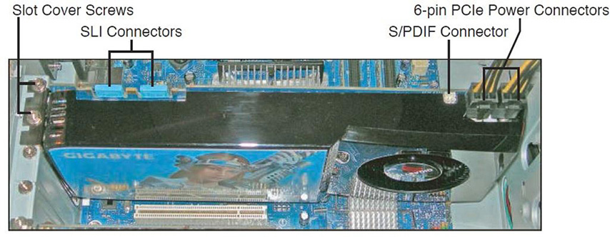
Figure 11.3 An installed PCIe video card
Step 8. Test: Testing is simple: plug in the monitor to the video card’s port and boot the computer. If you don’t get anything on the display, it’s time to troubleshoot. Make sure that the monitor is connected securely to the correct port. Then (after shutting down the PC) make sure that the card is seated properly and that the power connections and any other connections are connected firmly. Listen for any beep codes that might be issued by the BIOS/UEFI POST. Check if the computer is booting without video; this can be done by watching the LED lights on the front of the case and listening for the power supply fan and hard drive activity.
Step 9. Install the driver: When the system boots properly, install the driver from the manufacturer’s disc. If no disc was supplied with the device or it is missing, or if you don’t have an optical drive on the computer in question, go to the manufacturer’s website and download the latest version of the driver for the exact model of the video card.
Step 10. Test again: Now that the driver is installed, test again. Verify whether the card is shown as the correct make and model in Device Manager (Run > devmgmt.msc). Then make sure the display can output the desired resolution. Keep in mind that some video cards can output a higher resolution than a monitor can support. If the computer is used for graphics or gaming, open the appropriate application and verify that it works as expected. For example, check for fluidity, quick response, frame rate, and so on.
ExamAlert
Know how to install and test a video card.
Note
Check out this video of a step-by-step video card install/upgrade on my website: https://dprocomputer.com/blog/?p=1699
Sound Cards
The sound card is responsible for generating sound from the data sent to it by the operating system. Audio devices can be integrated into the motherboard, installed to PCIe slots, and can be connected to USB. However, the typical audio device known as the sound card is installed to a PCIe slot on the motherboard.
Sound cards are not used as often as they once were. With the advent of USB 3.0 and beyond, many manufacturers choose to design their speakers and headphones with USB-only connectivity—or they are wireless. However, some still utilize connections that require a traditional sound card. And some audiophiles are concerned with the potential for USB latency, or wireless interference, and prefer the direct connectivity—and ports—that a sound card offers. Generally, the connections are 1/8-inch (3.5 mm).
Most sound cards are color-coded. This color scheme was originally defined by the PC System Design Guide, version PC 99 (which was finalized as version PC 2001—and the colors stuck even today). It specifies the following colors for the TRS 1/8-inch (3.5 mm) mini-jacks like the ones shown in Figure 11.4:
• Light blue: Line input. Sometimes this seconds as a microphone input.
• Pink: Microphone input.
• Lime green: Main output for stereo speakers or headphones. Can also act as a line out.
• Black: Output for surround sound speakers (rear speakers).
• Silver/Brown: Output for additional two speakers in a 7.1 system (middle surround speakers).
• Orange: Output for center speaker and subwoofer.
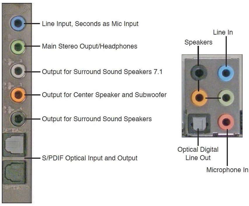
Figure 11.4 A typical sound card’s ports and integrated audio ports on a motherboard
On the sound card shown in Figure 11.4, note an optical input and output. This is known as a Sony/Phillips Digital Interconnect Format (S/PDIF) port. This particular version of S/PDIF is called TOSLINK. It delivers high-quality digital sound over fiber optic cable. It is also known as a digital optical port.
Some users prefer to use an external audio interface that connects via USB, but provides plenty of different connectivity options that are easily accessible on top of a person’s desk. They usually offer high-fidelity sound (for example 24-bit/192 kHz). These normally require a USB 2.0 or higher, but for greater productivity and less latency, USB 3.0 is often recommended.
Other Expansion Cards
There are expansion cards for just about anything you can think of. Many motherboards come with integrated network cards, USB ports, and so on. But sometimes a user simply needs a more powerful solution or more ports.
Motherboards usually have one RJ-45 port for a wired Ethernet connection. However, a user might require more. Network interface cards are available that have one or more RJ-45 ports that can be used for connections to other networks, or can be “teamed” together to provide link aggregation (combining the bandwidth of each port), and to offer redundancy in case one port fails.
Most motherboards have plenty of USB ports, but if not, then USB hubs can be connected to a USB port in order to add devices. But what if the motherboard doesn’t have the right version of USB? For example, if your motherboard had USB 3.0 SuperSpeed ports, but you wanted to make use of a device that can run USB 3.2 SuperSpeed+ at 20 Gbps. Then you would need to add a USB 3.2 expansion card.
There are also external SATA-based devices (eSATA). A few motherboards come with these ports, but if you need to connect to external hard drives that use eSATA, then you might need an adapter card.
All of these cards are installed in a similar way to the video card, but they are simplified. Simply unscrew the slot cover, and insert the expansion card straight down into the slot. Try not to wiggle the card, and only hold the card from the edges to avoid ESD or other damage. Then, screw the card in. Check the card in the Device Manager (or similar tool in other OSes) to make sure it is seen properly, and if not, download the driver from the manufacturer and install it. Test the card to make sure it works properly, and then checkmark another tech job that’s been well done!
ExamAlert
Know how to install, configure and test sound, network, USB and eSATA expansion cards.
More Ports and Connectors
The main type of drive technology on motherboards is Serial ATA (SATA). SATA supports the connection of hard drives and optical drives. So, most motherboards come equipped with several 7-pin SATA connectors, and possibly one or more 18-pin SATA Express connectors. The A+ objectives also make mention of IDE, but it is rare that you will see it. We talk more about hard drive technologies in Chapter 10, “RAM and Storage.”
You will find other ports as well, such as: integrated audio ports, for use with an optical drive or sound card; internal USB ports, for the front panel USB connections; and a variety of power connections which we will discuss further in Chapter 13, “Peripherals and Power.”
Then there’s the case connector group. The case connector group is usually on the edge of the motherboard and it allows connectivity for the front panel connectors. These wires start at the inside front of the case and have thin 2, 3, or 4-pin plugs on the other end. They are labeled with names such as POWER LED, POWER SW (for power switch), HDD LED, and so on. These plugs connect to items such as the Power button, reset button, and LED lights.
Computers with limited motherboard space might come with a riser card. The riser card can provide for additional expansion slots such as PCIe (and PCI). It generally plugs into one of the expansion slots and allows for an additional two slots typically. This allows a person to take advantage of three-dimensional space, but it could decrease airflow leading to increase heat. Riser cards are more common in small proprietary designs and with small form factor motherboards.
BIOS/UEFI Settings
Historically, the Basic Input Output System (BIOS) has been the firmware loaded on most desktop and laptop computers. However, since 2005 the Unified Extensible Firmware Interface (UEFI) has gained in popularity to the point where in 2014 it became the predominant type of firmware shipped with motherboards. But many technicians (and even some manufacturers) will still just refer to it as “BIOS” or possibly as “UEFI/BIOS.” For simplicity during the course of the book, I often refer to a motherboard’s firmware simply as BIOS.
UEFI communicates more effectively with the operating system, allows for a mouse-driven firmware-based setup program (instead of the menu-based BIOS setup program) and includes advanced system diagnosis (except for the worst of errors, such as the CPU failing). It also has a built-in secure boot mode, which prevents digitally unsigned drivers from being loaded and helps prevent rootkits from manifesting themselves. It has faster startup times than the BIOS. It also allows for the hard drive usage of the GUID Partition Table (GPT) which supports more partitions (128) and larger drive sizes than the older master boot record (MBR) option. We will discuss GPT and MBR further in the 220-1002 portion of the book.
The firmware is loaded onto a chip on the motherboard and can (and should) be updated or “flashed” periodically to take advantage of the latest functionality and security updates. There are several ways to update the firmware, but generally you would either do it from within Windows, or by using some kind of bootable media (USB flash drive or USB flash drive) to boot the system and rewrite the firmware—also known as “flashing the BIOS”.
This firmware stays resident in the computer after restarts. However, time and the individual settings that you select are stored elsewhere, for example in a complimentary metal-oxide semiconductor (CMOS). This chip is volatile meaning that the settings could be lost if the computer is restarted. That’s why the motherboard comes with a lithium battery (also known as a CMOS battery). That battery retains the individual settings and keeps time while the computer is shut down. The most common battery used on today’s motherboards is the CR2032, a nickel-sized battery that snaps into the motherboard and has a shelf life of anywhere from 2 to 10 years, depending on usage. The more you leave the computer on, the longer the battery lasts.
The BIOS is where you go to set a password, change boot options, configure time and date, configure devices, overclock the computer, and much more. Accessing the BIOS must be done before the operating system boots. This can be accomplished by pressing a key on the keyboard, for example F2 or DEL. Different manufacturers will use different keys. Here are a couple of examples of settings you might modify in the BIOS:
• Boot options: Also known as BIOS boot order or device priority, this setting enables you to select which media will be booted: hard drive, USB, optical drive,over-the-network, and so on. Usually, this should be set to hard drive first. But if you install an operating system (OS) from removable media, you would want to configure that removable media as first on the boot options list. For a secure and trouble-free system, it is recommended that you set this to hard drive first, as shown in Figure 11.5. If the system is set to optical drive first, and there is a disc in the drive, it could cause Windows to fail to load properly and could pose a security risk. You’ll note that the first boot device in the figure says: “Windows Boot Manager,” P1, and the name of the device—a 250 GB Samsung solid-state drive. Windows Boot Manager is the primary boot file in Windows and it is the first file on the hard drive that the BIOS looks for when it starts up. P1 means the first physical SATA port connection.
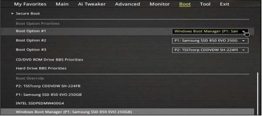
Figure 11.5 BIOS Boot Order
ExamAlert
Know how to set the BIOS boot options! Also, if you boot a PC and see a black screen with a white blinking underscore on the top left, the issue could be the boot order.
• Passwords: Two passwords are available on most BIOS: User and administrator. The User password authenticates a user before it enables the operating system to boot. The administrator password authenticates a user to the BIOS Setup Utility itself. For a secure system, enter a strong administrator password. By strong, I’m talking about length and complexity my friend!
• More security settings: Secure boot is an option on UEFI-equipped systems. If enabled, it blocks rootkits and other malware from launching boot loaders that have been tampered with. Newer versions of Windows make use of a certificate that is stored in the UEFI which will check the boot loader for authenticity—meaning whether it has been digitally signed by Microsoft. If the hard drive’s boot loader is not authentic, then the computer will not boot to that hard drive. To allow for hard drive encryption, some motherboards come with a trusted platform module (TPM), a chip that stores encryption keys—it can be enabled in the BIOS. We’ll discuss computer security in more depth within the 220-1002 portion of the book.
ExamAlert
Secure UEFI-equipped systems with secure boot and TPM.
• Virtualization support: To support virtual computing, the BIOS must be configured properly. This setting is often buried within the BIOS in a CPU submenu. For Intel CPUs, the Intel Virtualization Technology (Intel VT) option should be enabled. For AMD CPUs, enable AMD-V. We’ll talk more about virtualization in upcoming chapters.
The POST
The power-on self-test (POST) is essentially a piece of code that the UEFI/BIOS runs to find out which type of processor is on the motherboard and verifies the amount of RAM. It also identifies buses on the motherboard (and other devices) as well as which devices are available for booting.
The BIOS indicates any system problems that the POST finds by either on-screen display codes, beep codes, or an integrated error code readout on the motherboard itself. The exact code(s) will depend on the type of BIOS used. Your motherboard should come with documentation about any possible BIOS error codes. If not, the documentation can usually be downloaded from the manufacturer’s website; you just need to know the model number of the board. In the case of a proprietary computer (Dell, HP, and such), you need the model number of the computer to download any necessary documentation from its website. We’ll be discussing more computer troubleshooting when we get to the chapters within Domain 5: Hardware and Network Troubleshooting.
ExamAlert
The POST is a built-in troubleshooting tool provided by the motherboard. Use it!
Cram Quiz
Answer these questions. The answers follow the last question. If you cannot answer these questions correctly, consider reading this section again until you can.
1. Which motherboard form factor measures 12 inches × 9.6 inches (305 mm × 244mm)?
![]() A. microATX
A. microATX
![]() B. SATA
B. SATA
![]() C. ATX
C. ATX
![]() D. mITX
D. mITX
2. Which component supplies power to the CMOS when the computer is off?
![]() A. Lithium battery
A. Lithium battery
![]() B. POST
B. POST
![]() C. Power supply
C. Power supply
![]() D. BIOS
D. BIOS
3. To implement a secure boot process, which device should be listed first in the Boot Device Priority screen?
![]() A. Network
A. Network
![]() B. CD-ROM
B. CD-ROM
![]() C. USB
C. USB
![]() D. Hard drive
D. Hard drive
4. Which of the following connectors would you use to power a video card?
![]() A. 24-pin power
A. 24-pin power
![]() B. 6-pin PCIe
B. 6-pin PCIe
![]() C. Molex
C. Molex
![]() D. 3.5 mm TRS
D. 3.5 mm TRS
5. Which of the following is a chip that stores encryption keys?
![]() A. Intel VT
A. Intel VT
![]() B. Secure boot
B. Secure boot
![]() C. Firmware
C. Firmware
![]() D. TPM
D. TPM
Cram Quiz Answers
1. C. ATX boards measure 12 inches × 9.6 inches (305 mm × 244mm). microATX boards are square and measure 9.6 × 9.6 inches (244 mm × 244 mm). SATA is a type of hard drive technology and the port used to connect hard drives to the motherboard. mITX (or Mini-ITX), also square, measures 6.7 × 6.7 inches (17 cm × 17 cm) .
2. A. The lithium battery supplies power to the CMOS when the computer is off. This is because the CMOS is volatile and would otherwise lose the stored settings when the computer is turned off.
3. D. To ensure that other users cannot boot the computer from removable media, set the first device in the Boot Device Priority screen to hard drive.
4. B. A video card is normally powered by a 6-pin or 8-pin PCIe connector. Lesser cards are simply powered by the PCIe bus. The 24-pin power connector is the main connector that leads from the power supply to the motherboard. Molex is used for fans, older IDE drives, and other secondary devices. 3.5 mm TRS (or 1/8 inch) is an audio connection.
5. D. To perform hard drive encryption, some motherboards come with a trusted platform module (TPM), a chip that stores encryption keys—it can be enabled in the BIOS. Intel Virtualization Technology (VT) is part of the firmware that supports the use of virtualization software such as Hyper-V and VMware. Secure boot can block rootkits and other malware from launching boot loaders that have been tampered with. Firmware (such as a motherboard’s BIOS) is should be updated or “flashed” periodically to take advantage of the latest functionality and security updates.