The key feature of a building that possesses a framed structure is that the bales and plaster are not called upon to bear the loads of roof and floors. In some designs, the bale walls share the job of resisting shear loads, but in most cases they act simply as insulation, and as a support for the plaster finishes. In this chapter we will look at several practical framing systems, but first we must address the question of why you should consider these methods.
Why Framed?
The choice between framed and Nebraska-style systems is basically one of design flexibility. While simple Nebraska-style buildings can be elegant and useful structures, they also come with a substantial set of design restrictions (see chapter 6, “Nebraska Style”), which limit the range of situations over which they are practical. In the vast majority of cases, a framed approach is better suited to the demands that we and Mother Nature place on cold-climate buildings.
These demands fall into two categories: those that come into play during the construction process, and those that affect how the building will perform over the long term. The three main issues facing bale walls during the construction phase are weather, inexperienced contractors, and nervous (or occasionally obstinate) building officials. Framed approaches simplify the relationship between the building process and these three constituencies. A fourth issue comes into play here, as well. Laying bales into a frame is a smoother, simpler process than dry-stacking them into a wall. Because there is less to worry about, it’s more fun.
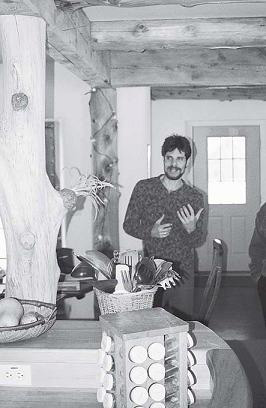
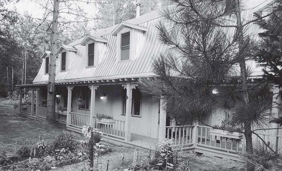
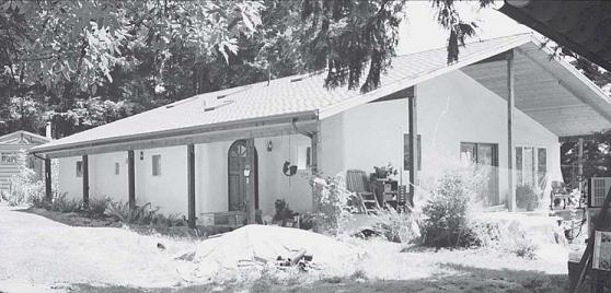
A visible interior wooden structure beautifully complements the soft curves of plastered bale walls. Wisbaum home, Charlotte, Vermont.
The factors influencing the long-term success of the building are somewhat more complex. They involve a set of trade-offs between the structural capabilities of the bales, and the needs and wants of the building’s occupants. When it comes to the ability of the wall to accept snow loads, to go up two or three stories in height, to include lots of windows to let in scarce winter light, and to maximize the owner’s investment, infill designs typically outperform Nebraska-style designs.
Construction Phase
Because the essential material in straw bale construction is extremely vulnerable to rainy weather and because of the unusual set of skills required to put a bale wall together, the bale phase of a project tends to become a project in itself. Let’s see how framed structures simplify the bale work.
Rain during the Construction Season
Unlike most rough-stage materials, bales must be kept dry throughout the construction process. On small projects, tarps tossed over the walls—or even a large tarp strung over the entire site—can be effective. On larger buildings, however, tarping can just about become a subtrade of its own, sapping time, energy, and money that is best reserved for actual construction. Plus, complex tarping systems always leak.
A sophisticated straw bale house design will take these factors into account, and will plan the construction process accordingly. While it is not essential that the roof go up before the walls go in, this pattern certainly simplifies the job of keeping the bales (and the builders!) dry. This is primarily because the roof sheds vertical rain, but it also provides a handy nailing surface from which to hang tarps on sites and in construction schedules where the walls need to be protected from wind-blown rain.
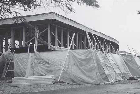
Providing effective rain protection can be a construction project in its own right.
Of course, the best way to protect the bales from this horizontal rain is to get on a first coat of plaster, as the walls go up. In any work party, some people will prefer mudding to the heavier and pickier bale installation. If you can round up and are capable of managing a large group (thirty or more people) it is realistic to have both of these processes happening at once. This is not practical on a Nebraska-style building, where the walls are usually allowed to compress somewhat before the finish is applied.
In situations where there will be a time lag between bales and plaster, a fallback is to nail a scrap board to the bottom edge of each tarp; the tarp can then be rolled around the board and up to the roof, leaving free access to the outside of the wall. At the end of the workday the tarps are allowed to fall back into their nighttime position, blanketing the walls. Jon Haeme, of Kempton, Illinois, came up with an improved version of this system; he stakes the bottoms of his tarps at a distance out from the building, creating pitched tent walls all around the perimeter, under which he works with minimal interference.

Jon Haeme, of Kempton, Illinois stakes the bottoms of his tarps at a distance out from the building, creating pitched tent walls all around the perimeter, under which he works with minimal interference.
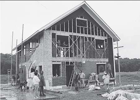
Plaster going on the first story as the bales go into the second, all under a roof as the rain comes down!Gould/Crevier home, Leverett, Massachusetts.
The wetter your climate, the more compel-ling rain protection becomes, not only because the bales are more likely to get wet, but also because they will be harder to dry out if they do get wet. If you live in a place where an occasional thunderstorm comes ripping through a generally dry environment, you might chance the possibility of a storm catching you with your tarps down, as any water that gets into the bales should have ample opportunity to dry out. If you live in a place with consistently humid and rainy weather, on the other hand, your design had better assume that the bales require continuous protection. An unprotected bale wall, in our experience, summons rain clouds about the same way a trailer park attracts tornadoes.
Permitting
Code officials tend to freak out at the idea of a wall of bales supporting a roof. The concept of a conventional structure of wood, concrete, or steel, infilled with bales, is easier to grasp, especially if yours is among the first bale projects in the area. The bale walls, in this case, simply need to hold themselves up, resist fire, and provide acceptable compliance with electrical codes, all of which they are substantially documented as being capable of doing. (They also need to resist damage from moisture, of course, but even in this case, a frame makes permitting easier. Your inspector will be happy to know that in the unlikely event that the bales were to fail, you at least still have something holding up the roof.)
Inexperienced Contractors
Lack of local construction expertise can be the downfall of any well-designed building. It is typically easy enough, nowadays, to find a contractor who is willing to build a bale house. This does not, however, mean that he or she is actually fa-miliar with the process. In the best case, an in-experenced contractor will be learning on the owner’s time; in the worst case, he or she will fail to grasp a major issue (such as the need to keep the bales dry), which can result in hundreds or thousands of dollars wasted on remedial efforts.
If the frame of the building is constructed first, the contractor will inevitably feel more at home with the process, because the most essential element will have been built according to a familiar method. A lot less can go wrong. Since most contractors do not enjoy risks, they tend to work more efficiently when they are confident of the success of their endeavors.
More Fun, in Some Ways
Stacking bales is pretty well a right-brain opera-tion. Inches and feet, plumb and level, on the other hand, are left-brain concepts, at least when measured to the tolerances typical in building construction. Paul has found that while stack-ing bales, most people really don’t feel like worrying about whether the walls are plumb. The level seems a party-crasher, spoiling the good time.
So, by framing out the building in advance, the left- and right-brain functions are separated. You get in the framing mode, and put up the structure. Then you get in the kid-with-blocks mode, and lay in the bales, without having to worry about gross errors in judgment resulting in corners that flare out like the bow of a ship. Such corners can induce seasickness a thousand miles inland. You still need to pay attention to how you are stacking the bales, of course, and you still need to consult occasionally with the level; but with a structure in place outlining the work to be done, the majority of the bales can safely be stacked by look and feel. This construction pattern is also very well suited to wall-raising parties, as the opportunity for major errors is greatly reduced. Likewise, any unevenness that might creep into the bale-laying process poses no structural problems, which means it can be chalked up to “character.”
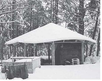
Building a roof before walls is crucial in projects that will progress slowly. With a complete roof, the bales can even be stored over winter.
Long-Term Issues
The long-term differences between Nebraska-style and framed construction generally revolve around the design limitations of the former method.
Snow Loads
In snow country, roof framing design can be based on significant live loads of 30 or 40 or more pounds per square foot. Because a “load-bearing” straw bale wall is really, in most cases, acting as a stressed-skin panel, this load is being transferred to the stucco and plaster skins. While wire-re-inforced cement stucco seems capable of pick-ing up these loads, as demonstrated by the Fibrehouse Ltd. tests (see chapter 6, “Nebraska Style”), there is some danger in requiring one wall component—the skin—to do the two most important jobs of the wall: keeping out the weather, and holding up the roof. In situations where at least one of these jobs is not difficult (no snow loads, for instance, or no driving rain or serious freeze/thaw cycles), this system seems practical, and durable. In cold, wet, snowy climates, on the other hand, Nebraska-style construction on the scale of a house might be a more dangerous bet.
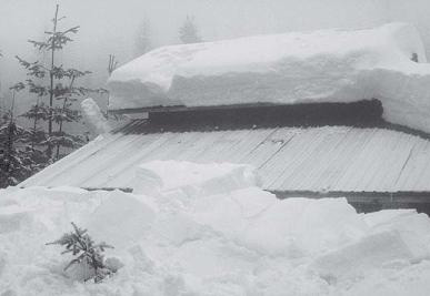
At the Park/Zimmerman house in northern Idaho, the north wall is sometimes completely obscured by snow!
Furthermore, it is unclear whether the load-bearing system will work well with lime or clay plasters, under snow-load conditions. The rigid-ity of a thin column of masonry held in place by wire and straw is what we are counting on, here. Lime might be rigid enough, clay probably is not. If the plaster is too soft to bear this kind of weight, then presumably both it and the bale substrate will flex under load. At the very least such flexure will open seams in the building envelope; at worst it will lead to serious cracking or spalling of the plaster, and moisture entry. (Then again, if the owner were to carefully main-tain the plaster, there might never be a real problem. It is forever amazing how designs that seem as if they should not work turn out just fine. Try it on a shed or guest house, maybe, and in fifty years we’ll see how it’s held up.)
If a strong structure is holding up the roof, the concerns mentioned above no longer apply. The skin now has one major job—to keep out the weather—and the designer is free to choose whatever surfacing material is most appropriate to the particular site and building. The structure, meanwhile, can be designed according to documented standards, so that it can be counted on to withstand centuries of winters.

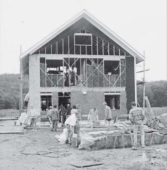
Framed structures allow variety. Here the first story walls are infilled bales and plaster, the second story is built of conventional materials. Weiss home, Charlotte, Vermont.
Two Stories
Roofs and foundations are expensive, in cold climates. Therefore, it typically makes sense to stack at least two stories of floor and wall between the foundation and roof. Given the same total square footage, it is also easier to achieve a pleasing quality of light in a taller, narrower two-story house, versus a low, spreading one-story version. Bales, and especially two-string bales, do not seem to be made to go two stories, in a load-bearing situation. They simply are not rigid enough. In addition, the nherent unevenness of individual bales, compounded over 16 or 20 feet of height, can make for a very uneven wall top, leading to problems in leveling and squaring the roof-bearing assembly. Add to this the wobbliness of bales at this height, and you find people in a potentially dangerous situation trying to maneuver roofing members into position while the wall on which they stand sways below them. (The Prestressed Nebraska system does seem to minimize some of these problems. Two stories are possible, and the wall is rigidified before the roof goes on. See “Prestressed Nebraska,” in chapter 6.)
If the bales are stacked around or into a frame, these issues are avoided. Bales have no problem going two or three stories if they need only support themselves. Balloon-stacked around a frame, the bales provide a continuous layer of insulation over the entire wall. If the bales are stacked into a frame, such that each course of bales sits on a floor deck, there is pretty well no limit on how high they can go. One could, conceivably, infill a skyscraper with bale walls.
Lots of Windows
Unlike desert houses, whose main function is to shelter people from the sun and heat, cold-climate houses should be designed to let in the sun for heat and daylight, and to maintain the sanity of the people who will probably be inside the house for a good portion of the year. This means that cold-climate houses usually have lots of windows, which break up the masonry structure of the bale wall. A common ex-perience has been that the supplementary framing required to box out window openings, to shore up narrow columns of bales, and to bear roof point loads, ends up being so extensive that the supposedly Nebraska-style wall turns into a disconcerting mishmash of structural systems. Such designs are difficult to build and difficult to remodel. They also make building inspectors uneasy.
There is really no “best” way to frame a bale-walled building. Some systems are used more often than others, but no one method applies in every case.
One of Paul’s favorite structural systems, first detailed in print by Paul Weiner of Design Build Consultants in Tucson, Arizona, actually employs the framing at the sides of the windows as load-bearing columns. Instead of acting as pesky holes in the fabric of the wall, frequent windows, in this method, bring a rational rhythm to the building’s structural support system. More on this later in this chapter.
Less Expensive
Infill bale construction tends to be less expensive than Nebraska style, because of what Paul calls the “fiddle factor.” One of the reasons bale construction is so much fun is that it is inher-ently imprecise; measurements are necessarily estimations, exact plumb and level can be hard to determine. If any significant percentage of the labor is to be paid, however, all of this fiddling with bales can drive the cost of the walls through the roof, or at least through the roof-bearing assembly, which really does want to be square and level, so that the roof framing, sheathing, and cladding can proceed in an efficient manner.
If the roof and its support structure are already in place before the bales go in, then a roof-bearing assembly is no longer necessary. Additionally, if the windows and doors are framed rigidly in place, then these become reference and anchor points for the bale wall. Assuming the structure is designed so that the bales do not require excessive modification, the walls can be laid up relatively quickly, and therefore, at a lower cost.
Bales being stacked around a heavy timber frame.
We often hear claims that Nebraska-style bale construction should be less expensive than infill because, since vertical columns are omitted, less material is used. This is not necessarily the case. Because wood (or concrete, or steel) is very strong in compression, very little of it is required to stand vertically, in order to support a roof. Also, in Nebraska-style walls horizontal wooden members (roof-bearing assembly, window fram-ing) tend to be quite wide, on account of the width of the walls. Since these components are much narrower in a framed structure, wood use tends to be fairly comparable between the two systems.
Methods
There is really no “best” way to frame a bale-walled building. Some systems are used more often than others, but no one method applies in every case. This is one of the great joys of bale construction—it is flexible enough to allow the designer a wide range of responses to variations in site, neighborhood, needs of the client, and locally available materials and skills. Designers and owner-builders should be wary of self-described straw bale “consultants” who promote a particular construction system. This is an inevitable sign of inexperience. (See “Straw Bale Reality Check,” in chapter 1.)
Non-load-bearing bale systems break down into four general categories, depending on the relationship between the bales and the structural frame. The first three methods typically employ a heavy frame of timber, concrete, or steel. In the “bale wrap” system, the bales are stacked around the outside of the frame, such that the frame is left exposed to the interior. In the “infill” method, the bales are stacked between the framing members; the frame disappears completely into the wall. If the frame is allowed to “float,” different strategies are employed in different walls, such that the load-bearing members are sometimes exposed, and sometimes hidden. The fourth method meshes bales with conventional stick framing. The bales can be stacked inside, outside, or between the light-gauge framing members.
The Bale Wrap
We have had good luck wrapping bales around timber frames, basically using the bales as a replacement for the foam-core, stressed-skin panels that have come to dominate the timber-frame enclosure market. The frame, in this case, does not need to be made of joined timbers; heavy wooden members, laminated or engineered beams, or built-up 2-by stock, connected by hardware, can also work well. Some builders also like the idea of a steel frame wrapped with bales; the contrast between the plastered wall and the machined steel could be quite striking.
When it comes to long-term durability, the wrap might be the safest of the bale construction systems. As Stuart Brand points out, tim-ber-framed buildings tend to be more durable than stick-framed buildings because “the wood structure is protected from the weather, it is massive, and it is exposed. Air and eyeballs can get at it to keep it dry and inspected.”1
Foundation
Many foundation systems are possible with the bale wrap. The key point is that the foundation (or at least the floor deck) must be extended beyond the load-bearing structure, to carry the weight of the bale wall. This extension will vary between 14 and 24 inches, depending on the type and orientation of the bales.
If the building sits on a slab, the matter is simple. The bearing points (where columns come down to the slab) must be sufficiently thickened to carry the loads associated with the structural frame. The width and depth of these bearing pads will vary with design loads and soil type, but their pattern will follow the standards for interior bearing walls (or posts).
If, on the other hand, the bales and structure are to sit atop a framed floor and over a basement or crawlspace, the most common course of action is to place the foundation wall at the perimeter of the floor deck, as in a normal house. The bales and plaster, which also come to the outside edge of the floor system, bear directly through the framing, onto the foundation. This means that an ancillary system must be installed to support the interior frame, which will other-wise rest on top of an unsupported section of floor. Usually, a set of columns are added in the basement, directly below the bearing points of the frame, to carry the structural loads of the building straight down to pads poured integrally with the basement floor. These can be steel-and-concrete lally columns, or if the basement is to be finished, they can be of wood. They do not generally get in the way, because they are quite close to the walls. Wooden columns are actually very convenient as places to fasten and hang the many accessories typical of basement life.
If your bale wall is relatively narrow, and you are blessed with an adventurous concrete contractor, you might substitute pilasters for these columns. (A pilaster is like a giant, structural shelf bracket.) These would, presumably, be poured integrally with the basement walls.
If the building is to sit on piers, the only way to support a bale wrap is to cantilever the floor, so that the structural columns bear down onto the piers, while the walls sit out on the cantilever. This is not a bad idea over a basement or crawlspace, either. It is one very direct answer to a complaint sometimes leveled against bales by those who are accustomed to skinny walls— that they take up too much floor space. Here the foundation footprint is the same as what it would be under a thin-walled building, and the thick-ness of the bale wall hangs out beyond. The floor framing and roof still need to be extended, of course, but this is a small price to pay for the beauty and insulation of the bales.
Working with a design load of 22 to 25 lbs/ square foot per course of flat-laid bales and plaster, the load imposed by a standard 6- to 8-course bale wall should be well within the tolerances for a cantilevered 2-by-10 or 2-by-12 floor joist system. The assumption here is that the interior plaster skin bears directly through the framing, onto the carrying beam or foundation wall. If the building is more than one story high, each floor will have to be cantilevered, in order to divide the weight of the bales and plaster. This strategy offers the fringe benefit of providing a band of framing halfway up the wall, a handy attachment point for porch roofs, decks, swimming pool slides, Batman poles, additions, scaffolding, or anything else that may be invented by present or future collusions between homeowners, designers, and builders.
The main drawback to a cantilevered floor is that it can look rather strange. It might not be a bad idea to stack stones at the perimeter, if light to basement windows is not an issue. Insulation and air sealing in a cantilever can also be tricky— the overhanging portion of the floor deck should be detailed pretty much like an outside wall, with proper attention to air tightness and insulation.
DEAD LOADS ON FLOOR
OF BALES AND PLASTER
2-STRING BALES, 36" LONG X 18" WIDE X 14" HIGH
Laid flat: 10 pounds per square foot per course
On edge: 13 pounds per square foot per course
3-STRING BALES, 46" LONG X 23" WIDE X 16" HIGH
Laid flat: 11 pounds per square foot per course
On edge: 16 pounds per square foot per course
Sand-based plasters: 10 pounds per square foot of wall area
(or 80 pounds per running foot of 8-foot wall)
Gypsum plaster: 5 pounds per square foot of wall area
(or 40 pounds per running foot of 8-foot wall)
Window Framing
Framing windows in bale-wrapped walls can be simple or complicated, depending on the design. In a one-story structure, window framing is easy: 2-by-4s run up each side of the window, from the floor to the soffit. Single verticals work fine, structurally; you can double them to provide a wider nailing surface for casing or lath, or to make your building inspector happy. Doubled-up framing makes a more natural reveal around the window; with single members, the bale returns can feel as if they are crowding in against the window unit. Single or double horizontal 2-by-4s work as sill and header. The header is not actually bearing any load, just holding the window in place. Cripple studs are omitted, as they wouldn’t be doing anything but getting in the way of the bales.
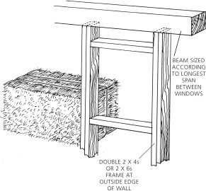
Whenever possible, size the window framing to a bale length, so that bales can be stacked in a column below the window.
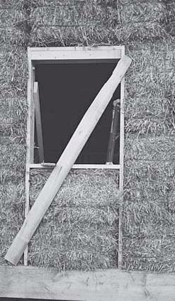
A frame rigged out and ready for the bale infill. The bale in the photo is a temporary bench. Stevens/Simons home, Leverett, Massachusetts.
Whenever possible, it is best to size the window framing to the bale module. This allows the bales below the window to be stacked in a column. Depending on the character of the bales and whether the framing is doubled, the bales’ outside corner might or might not need to be shaved off, so that they can slide between the studs. Given the 3-foot-length typical of two-string bales, the framing is easily enough spaced to yield the 33- to 34-inch rough opening that is required for a 32-inch window. Standard rough openings are 1 inch larger than the window unit, but here it is best to go a bit wider. This leaves room both for a bead of spray foam, and for any tweaking the framing may take during bale installation. If the windows will have nailing flanges, be sure they can accommodate the increase in rough opening width!
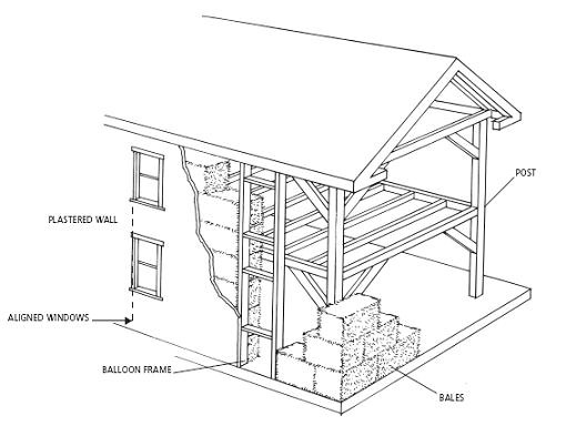
Window framing is not always more complicated in a multistory, bale-wrapped structure. If the upper-floor decks are cantilevered out over the first floor, window openings on each floor can be platform-framed. If the upper-floor framing is not extended, but all or most of the windows on each story are made to line up vertically with those above or below them, then the windows can be balloon-framed, from the floor deck to the soffit. This may sound strange at first, but it is quite common on old houses, and lends an organized appearance to the building’s facade. On the interior, the rhythm of the windows will mesh quite naturally with the regular pattern of exposed framing members. If most of the windows are kept to such a pattern, the occasional oddball can be scabbed in according to one of the methods described below, or allowed to float in the bale wall.
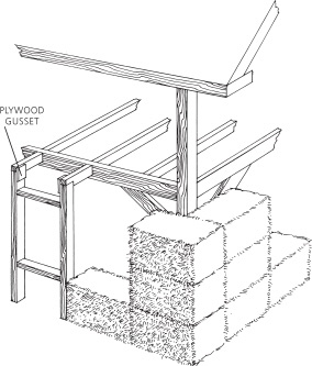
If the windows are not to be stacked on top of each other, things get more complicated. The first-floor window frames can be built to the height of the beam separating the first and second floors; horizontal outriggers can then return to the beam, where they are hung in joist hangers, or toe-nailed. The attachment between window frames and horizontal returns can be made with a plywood gusset or mending plate. Needless to say, this unit is built on the ground, in one piece; it is then stood up and nailed down to the floor deck and in to the beam. It’s not an ideal system, but it becomes quite stable, once the bales are in place.
Framing second-story windows is a further challenge. One option, which can be practical on walls with a lot of windows, or where the building is to be furred out for siding, is to create a full-height skeleton of 2-by-4 framing at the window plane. The first-floor windows would be framed to beam height, and topped with a doubled-up plate. Second-floor window framing would then rise from this plate to the soffit. Ancillary studs between window openings will probably not be necessary, as this superstructure is not bearing any real loads. The plate should be tied back to the beam every 6 or 8 feet, depending on the length of bale used. The course of bales at the plate height will need to be grooved to accept the plate. Though it will slow the bale-laying process somewhat, this grooving should not be a major concern if the bales are to be laid flat. If the bales are to be stacked on their edge, however, you had better make sure that the plate falls at a break between bale courses. If you’ve ever attempted to groove the string face of a bale between the strings (or worse, at a string) you will understand the impracticality of doing so.
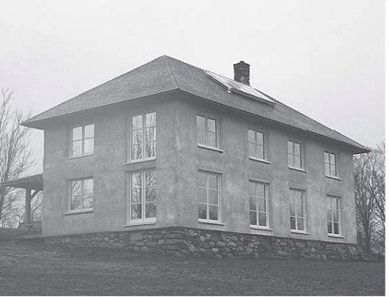
Aligning windows vertically simplifies the framing and gives the facade an organized appearance.Earth Sweet Home, Dummerston, Vermont.
Balloon-framed windows.
One-story window frame.

Two-story window framing with studs and plate.
The bales, in this configuration, will also need to be slipped between the tie-back framing members. This should not be particularly difficult if the returns are placed on centers that approximate the length of the bales. Don’t worry about throwing off the bales’ running bond at this point; the rigidity imparted by the framing makes the bale wall very stable. From the point of view of bale laying, this intersection can pretty well be treated as the starting point of a new wall.
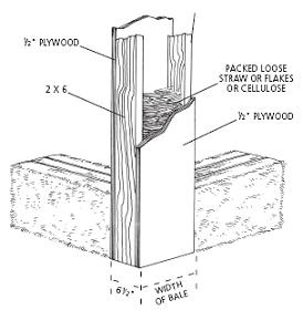
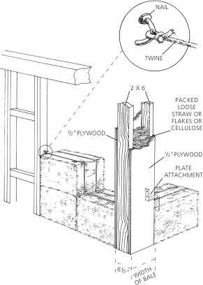
Another option is to place a wide plate (platter!) in the bale wall at the beam height, to provide a base on which to nail the frames for the second-story windows. Such a device serves a secondary function, as a way of fastening the bale wall to the main structure. This platter is also useful as a means of attachment for porch roofs, or any other exterior accessories. Indeed, it may be worth installing one just to ease remodeling. Architect Guy Snyder of Portland, Oregon, employed a wooden I-joist laid flat for this purpose. You might also fabricate your own version of it, sometimes known as a “track.” A track is basically a series of strips of 3/4-inch plywood cut to the width of the bale, with a series of 1-by-6s (or better yet, grooved 2-by-6s) screwed and glued to each edge. It would be best if the I-joist or track could be laid directly into the bale wall, at the appropriate height: this would simplify the problem of having to wedge the top course of first-story bales up and under this collar. Unfortunately, if part of its job is to hold the top of the first-floor window framing out away from the main structure, there is no practical way to avoid installing the collar as part of the process of standing the window frames. One other low-end detail is possible, here: extending the upper-floor decking material out into the bale wall. It could be beefed up by gluing and screwing a second layer of material on top, to yield, presumably, a 11/2-inch-thick collar, all around the building. The build-up will double as something of a toeup for the second-story bales.
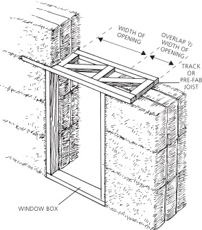
Window framing with “track” or wooden I-joist.
FLOATING WINDOW BOXES
Windows can also be allowed to float in the wall, as in Nebraska-style construction. This method inevitably involves more fiddling than its framed-in counterparts, and it removes the window frames as a reference and attachment point for the bale walls. Nonetheless, this can be a reasonable solution if you have only a few windows, or some oddball windows, on the upper story. Floating window boxes work best in situations where the load above them is minimal; if the box doesn’t need to support much beyond itself, the framing members can be scaled down substantially from the 2-by-12 and greater material that is typical of Nebraska-style construction. But 2-by-6 framing is the minimum here; just enough to allow for some attachment into the bale, inside the outer string. And 2-by-8 framing (or 2-by-4s sheathed with plywood, and the plywood extended back 8 or 10 inches into the opening) is better. The plaster, especially if it is wire-reinforced cement stucco, can be relied upon to do a portion of the job of holding the window in place.
If you really want to experiment with float-ing window boxes, the best place might be on a small window. Framing from floor to beam in order to place a 2 x 2 window, for instance, is not so obviously worth the trouble, because the bales above and below will need to be notched around the framing. The amount of bale displaced by the window, in this case, is so small that the window box can be kept quite lightweight, without any real concerns about settling. Such small win-dows can even be cut in with a chain saw after the wall is built.
Support of Bales above Windows
Because the window framing in the bale-wrap method is typically kept quite light, any bales that fall above a window must be supported by an ancillary system. There are four possible methods. The first and simplest is to omit the bales entirely. Second, these bales can be hung from the frame. Third, they can be supported by a simple lintel. As a last resort, the window box can be beefed up to where it can support the weight of the bales above.
OMIT THAT BALE!
Typically, there is no more than one bale above a window, in any given story of a building. Borrowing a detail from Edwin Chapin of Phillips, Maine, Paul usually omits this bale, substituting instead a piece of metal lath or sheetrock angled or curved from the top of the window up to the ceiling. It meets the ceiling at the plane of the inside face of the bale wall. This opens up the top of the window, allowing light to spread up onto the ceiling, and thus into the room. Except on very tall windows, this looks better than the heavy brow that is created by placing a bale above a window; it also makes the window opening feel more approachable for tall people. The hollow area behind the angled-forward plaster is blown with cellulose insulation, or stuffed with loose straw or fiberglass.
HANG THAT BALE!
Bales above windows, if you do choose to employ them, are often best hung, rather than stacked. Framing can almost always be found not far above a window; a sheet of metal lath nailed to the window header and looped up to the framing at ceiling level makes a fine, tight hammock for suspending a bale. The inside bottom edge of this bale will want to be rounded, anyway, to match the flare of the window openings and allow more light into the room; the natural curve of the lath conforms well to the bevelled bale. Furthermore, this surface will probably need to receive lath anyway, if you ever wish to get any plaster to stick to it; so you may as well allow the lath to do two jobs at once.
The potential difficulty with employing this technique on first-story windows of a two-story house is that the lath and window frame end up bearing a portion of the weight of the bales above. This is not necessarily a problem, for two reasons. First of all, if you have built in any sort of interstitial framing at the height of the beam between the two floors, then this framing picks up a good portion of the load from the second-story bales, and carries it in to the main structure. Second, this lath hanger system is really quite strong. If the lath must be assumed to be carrying the weight above, then the window header should be bulked up from a doubled 2-by-4 to standard header size for the size of the opening, and you should be sure to use the heavier gauge (3.4 rather than 2.5) of lath. We have had no problems with this system.
LINTELS
If you do find yourself in a situation where you have lots of bales over a window, and no ceiling or beam to attach the wire lath to, then you pretty well have no choice but to support the bales above with some sort of framing. If the rough opening is of ordinary size, say 3 feet wide or less, then a simple solution can be to insert a section of I-joist or track as a lintel above the window. This lintel should extend at least 18 inches to each side of the window, to properly spread the load of the bales above. (The general rule of thumb is that the overlap onto the wall at each side of the window opening should equal half the span of the lintel, over the opening.)
Across larger spans, you will need a heftier lintel. A box beam works well in this situation, framed (typically of 2-by-12s and 3/4-inch plywood) to come as close as possible to the depth of the bales it is replacing. (Extra depth can be filled with scraps of rigid foam, or shimmed up with wood and stuffed with loose straw.) Paul consid-ers this type of box lintel effective for spans out to 6 feet; following the rule of thumb from above, there should be 3 feet of overlap onto the wall, on each side of the opening. Thus, a box suitable for spanning a 6-foot opening would be 12 feet long.
Using a prefabricated joist as lintel above a small opening.
The steel lintels that are sometimes used in warm-climate construction are not appropriate to cold climates. Steel creates a thermal bridge between the inside and the outside of the wall, robbing the building of heat and creating a cold spot, an excellent point for mold growth, on the interior of the wall. The cold steel also creates a tremendous opportunity for condensation of any water vapor within the bale wall.
HEAVY-DUTY WINDOW BOXES
A final option is to build the window box itself strong enough to bear the load from above, as in Nebraska-style construction. The major drawback to this method is the depth of framing required around the windows, and the resultant loss in ability to round out the window openings. See chapter 6 for details, if you choose this route.
Bale Attachment
While attaching the bales to the frame is not absolutely necessary in the bale wrap method, it is obviously a good idea. This is especially true for buildings of more than one story in height. In cold-climate buildings we generally avoid attachment systems that involve running bolts from the inside to the outside of the wall; this is somewhat unfortunate, as they do provide a very positive connection. We have heard of threaded rods made of nylon, but we have never seen them. These could offer the perfect solution.
In the interim, however, the ever innovative straw bale community has devised some other workable systems. The operating assumption here is that the structure will be exposed on the building’s interior, and that, therefore, we cannot go wrapping twine or strapping around the framing members.
The most effective method is a variation on the Steens’ exterior pinning system (see chapter 6, “Nebraska Style”), where the interior pins (usually 1-by-3s) are attached to the outside of the frame, as part of the preparation for the bales. As the bales are laid in against this cage of vertical strapping, matching small-dimension members (1-by-3s or round stock) are added on the exterior of the bale wall, and fastened through, locking each bale into its position in the wall, and the entire wall tightly to the frame. The connection between inner and outer pins is usually made between the courses of bales, with every second course being adequate. This can be done with baling twine or with poly strapping.
Frame at a demonstration building, strapped with 1-by-3s and ready for bales. Aiperon Foundation, Coventry, Rhode Island.
As bales are installed, vertical strapping is added to the exterior and attached through the wall to the interior straps.
If the bales are to be conventionally pinned, or not pinned at all, then the connection must be made directly between the bales and the frame. (It is possible to tie conventional in-wall pins to the frame, but this is an unpredictable and picky process, best reserved as a secondary method.) The simplest method we have found is to use either baling twine or poly strapping, fastened off by means of large fencing or electrician’s staples, and tied around individual bales. The trick here is to use two staples for each bale to be fastened, one at the top and one at the bottom. This assures a stronger connection by dividing the tension in the fastening material; it also eliminates the sloppiness that inevitably results from trying to fasten a malleable rect-angle at only one point. We prefer strapping to twine, because the mechanical advantage associated with the strapping ratchet tool usually allows for a tighter connection. The small diameter of the twine allows it to sink between the straws under load (like when you step on it) such that the tightness of the connection cannot be trusted.
Bales secured in place, with plastering commencing.
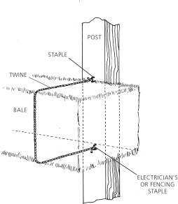
Fastening bales to the frame with twine.
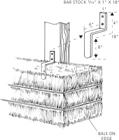
A homemade bale fastener.
A collar placed in the bale wall and fastened to the frame, at the break between stories, can also serve to stiffen and attach the bale wrap. This method works well in conjunction with periodic tying, as above. (See the discussion of platters under “Window Framing,” earlier in this chapter.)
A final option is to fabricate hardware out of steel bar stock. When working with bales set on edge, we have had success with a custom fastener made from 1/8-inch-thick, 1 inch wide, 18-inch-long material, bent in two places to form an L with a leg added to its bottom. This 8-inch bottom leg is pounded down into the bale, a bit more than 6 inches from its inner edge. The 6-inch horizontal portion of the bracket heads back toward the post, and the 4-inch vertical is nailed to the post, through two predrilled holes, drawing the bale tight to the frame. A large quantity of these fasteners can be bent in a vice, in fairly short order; and if the bales are dense they form quite a firm connection. This method would not work with bales laid flat, as the bracket leg would approach the straws in an inappropriate orientation.
Plaster
Plaster techniques do not vary much between styles of bale construction. The one unusual de-tail, in the case of the bale wrap, is that the exposed framing makes for a difficult job of maintaining a continuous air barrier layer over the entire wall. To deal with this issue, we have borrowed a detail from Building Science guru Joe Lstiburek. Before the bales are laid in, the back sides of all framing members that are to contact the bale walls receive a strip of sheetrock or plywood, which extends out an inch or more beyond each edge of the framing, into the plane of the plaster. Any joints are taped. The plaster is then run across the bales, and lapped over the protruding fins of sheet material, thus providing air barrier continuity behind the framing members.
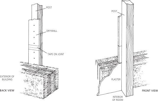
Providing for continuity of interior plaster with an exposed frame.
Siding
An internal frame is not the most efficient structural system to use on a bale house that is to be sided. The infill post-and-beam and stick-framed methods described below would be a more ideal choice if siding is to be used.
Nonetheless, timber-framed bale buildings have received wood sid-ing. If the siding is to be horizontal (clapboards or shiplap), the most popular procedure is to run 2-by-3s or 2-by-4s on the flat, from the floor framing (or a nailer shot into the slab) to the soffit, or to a nailer that is rigged out from the beam supporting the second-floor deck, and then on up to the soffit. Window and door framing, obviously, must be coordinated into this nailer system. We typically use 2-by-6s for the window and door framing, in this case, and hang the frames out 1 1/2 inches beyond the floor deck, to bring the framing to the same exterior plane as the nailers. In this manner, we avoid having to pad out the framing. It is usually necessary to add a nailer at each side of the framing, however, because the window casing will typically cover the nailing surface available from the frame itself. An ancillary benefit of this system is that the siding nailers become an attachment point for the bales.

The frame is furred-out with strips of plywood (or drywall) and ready for bales. When plaster is run onto these protruding fins, air-barrier continuity is maintained between frame and bales.
Vertical siding can often be simpler. If the siding boards are of true-dimension material and a nailing surface is available (or can be made avail-able) at the top and bottom of each story, then an additional nailer is only necessary at the midheight of each story. This can typically be fastened to the window and door framing, if the framing is sufficiently stout and sufficiently frequent. (Extra nailers will still be necessary around the win-dows.)
Under less ideal circumstances, you might find that to install vertical siding, you must first fur out vertically, as for clapboards, and then cross-hatch with 1-by strapping material. This is a rather material- and labor-intensive method, but it does work.
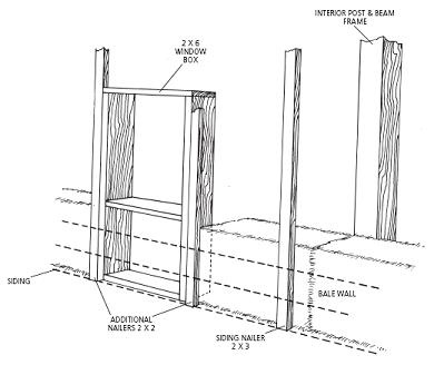
Supports for siding in the bale wrap.
Bale Infill
In general straw bale parlance, “bale infill” means any system in which the bales are acting in a nonstructural capacity. For the sake of clar-ity, we have substituted “framed structures” for this wider category, reserving “bale infill” for systems in which individual bales or panels of bale wall are built between the structural members, such that the framing system disappears into the wall. There are many ways to do this; the remainder of this chapter will look at some of the most popular and practical options.
Why
Bales,
Instead of
Panels?
In the big picture, bales function similarly to foam-core, stressed-skin panels, in that they form an unbroken envelope of insulation around both the load-bearing structure and the conditioned interior space. On the detail level, however, the two systems could not be more different.
Panels are the ultimate in expensive, factory-produced, site-labor-saving materials. They show up on the site and are often installed with a crane in one day. The roof and walls are instantly dried in. The interior plasterboard layer is mudded and taped, the exterior is sided, and the walls are complete. The homeowner and builder are happy—the job has been done well, costs have been strictly controlled. Unfortunately, very little of the homeowner’s money has entered the local economy; it has mostly gone to the panel manufacturer, who has sent a large percentage of it to foam and OSB manufacturers.
If the walls are made of bales, the job can be done equally as well. The process will cer-tainly take longer, especially if the plaster is applied by hand. Costs will be roughly comparable— probably 10 to 20 percent less for the bales in a tight design with volunteer-applied plaster, 10 to 20 percent more if too much time is spent in fiddling. Of the money spent, however, a much higher percentage will go to the people engaged in the work of constructing the walls. Of the sums spent for materials, at least a third will go to the farmer who produced the bales, the rest to production of framing and plaster materials.
The walls produced will look wholly different. If you like thin walls, flat planes, and crisp corners, the panels are for you. If you like deep, rounded window wells and soft surfaces, then bales are the way to go.
Which material is more durable is an open question. If bales get wet and stay wet, they’ll rot. Panels, on the other hand, are a home of choice to mice, termites, and ants. And nobody can tell you for sure that the glue that holds panels together will still be functioning a hundred years from now.
In the case of a fire, any sensible person would choose a bale-walled house over a panel-walled house every time. The plastered bale walls would ignite much less quickly than the panel walls, and the gaseous by-products of any combustion that did take place would contain far fewer chemical toxins than would be emitted by the foam and OSB panels. Additionally, far fewer toxic substances are required for the production of the bale walls. This makes them a superior choice from an ecological point of view. Finally, the bales can be composted at the end of their useful life. Depending on your choice of plaster, it may be able to accompany the bales to the compost pile. The panels, on the other hand, become garbage; they will never biodegrade, and their composite nature makes unlikely the possibility that they will be recycled as feedstock for other manufactured materials. Of course, maybe in some future of technological bliss, foam-fed ants will become a prime part of the human diet.
Bob Bourdon
A bale-wrapped, timber-frame structure which has 2-by-3 vertical nailers and 1-by crosspieces to support the pine siding. The Auberge “À la Croisée des Chemins,” Mont-Tremblant, Quebec.
Structural Window Frames and
Box-Column Corners
Paul’s favorite in-the-wall structural system for bale construction is an adaptation of the “modified post-and-beam” system first detailed by Paul Weiner in an appendix to The Straw Bale House. His system is a hybrid in that vertical columns (extensions of the window and door framing) bear the load of the roof, while the bales (or bale-and-plaster panels) provide the diagonal brac-ing. The windows and doors are framed to the full depth of the bale, to maximize the ability of the bale-and-plaster wall to resist shear.
Paul Dadell, for his home in Guilford, Vermont, developed a variation on this design. (And no, your name does not have to be Paul to use this method.) The door and window frames are still treated as load-bearing columns, but the framing is reduced to doubled-up 2-by-4s or 2-by-6s (or 4-by-4s or 4-by-6s) at each side of an opening. This framing is held flush with the outside of the bale wall, the plane in which the win-dows are most safely hung. The header and sill are typically framed of the same stock (doubled 2-by-4 or 2-by-6) used for the verticals, to create consistent nailing surfaces for fastening windows and casing. The assumption is that these need only support the window.
Dadell window frame.
Corner box column.
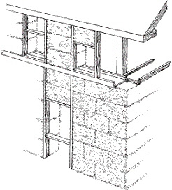
Corners are framed with box columns, typically built of 2-by-6’s and 1/2-plywood or OSB. Finished dimensions are 61/2-inches wide by 18 inches deep (for two-string bales, laid flat), by the height of the wall. The bales do not overlap at the corners; instead they butt into this hefty column, and are tied one to the other, and to the column itself. This detail eliminates one of the trickiest points in bale construction: the overlap-ping bale corner that always tries to lean out, as it goes up. These corners are very solid; they also provide a nailer that is an excellent attachment point for both siding and trim. Corner trim is a great aid to exterior plaster (especially cement stucco), because it serves as a control joint in an area that is particularly vulnerable to cracking.
A beam runs across the tops of these vertical members, sized according to the longest span in the building. To control this longest span, a box

Box column and structural window frames, with plywood (covered by house wrap) for diagonal bracing below windows.
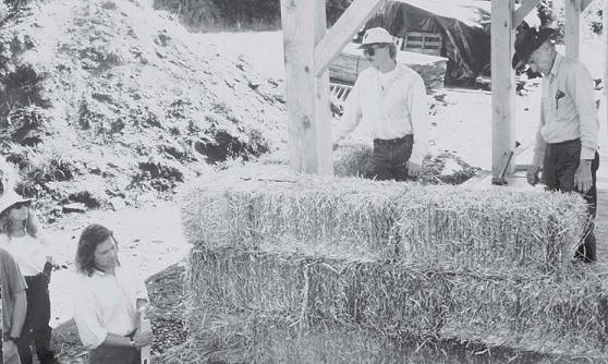
“Barn-Raisings”
Bales and plaster work well with timber frames, because they fit nicely into the “barn-raising” tradition. Rarely is an owner-built timber frame erected on a weekday with a crane; raising day is almost always a Saturday, and it inevitably involves lots of friends and lots of good food and beer. Owner-built bale walls, of course, are usually put up in the same fashion. A marriage of the two makes obvious sense. The real Tom Sawyer trick is to lure those people back for a plastering party. Odds are, if they had a good time with the frame or the bales, you can get them to bring others along to help with the plaster. Then, not only will the work get done more quickly, but you’ll make a bunch of new friends in the process! column may be inserted into any run of wall (a north wall, most likely) whose length is out of scale with the rest of the wall panels in the building.
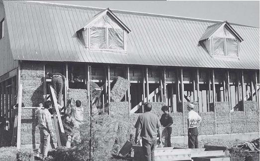
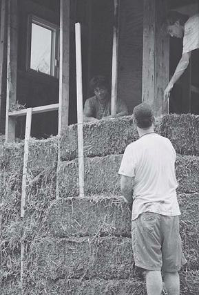
With the frame up and the roof on, installing the bales is a party.
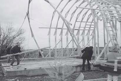
A barn-truss system raised with the help of friends. Gabriel Cornu studio, Saint Germain, Quebec.
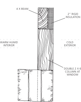
If the framing is 2-by-6s, the 4-inch beam can be set toward the interior edge of the frame, and the exterior-side space filled with rigid insulation.
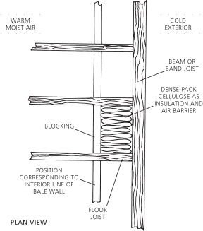
The Seldon dense-packed floor joists, plan view.
The slightly tricky detail here is how to insu-late this beam well, especially avoiding making it cold enough that it becomes a point for con-densation. If the vertical framing is of 2-by-6s, it may be possible to hold this beam in 1 1/2 to 2 inches from the exterior of the wall, and wrap it with rigid foam insulation. An alternative (and rather more elegant) detail comes from innovative carpenter Gary Seldon of Greenfield, Massachusetts. Gary’s method is to frame a cavity at the interior of the beam, by blocking in the joist system, more or less in line with the interior edge of the bale wall. The resulting cavities are then dense-packed with blown cellulose insulation. Unlike fiberglass batts or loose straw, dense-packed cellulose acts as an air barrier, so even though the beam is kept cold by the interior insulation, it is also kept out of contact with warm, moist interior air. Thus, condensation should not be a problem. The cellulose also acts as a defense against exfiltration at this very vulnerable location. Where a floor-joist system sits on top of the beam these same concerns apply, and the same details work for insulating at the band joist.
DIAGONAL BRACING
Though Paul Dadell did so in his one-story house, we typically do not rely exclusively on the bale/plaster panels for diagonal bracing in the structural window frame method. Steel-strap cross-bracing is the most common choice for shear resistance, because it can be held to the outside plane of the wall, and thus requires no notching of the bales. Nils Smith employed sheets of plywood at the corners and under the windows of Roberta Nubile and Oliver Kiehl’s house in Charlotte, Vermont. A hybrid of plywood (or OSB) and steel strapping is also possible, as at the Gould-Crevier house in Leverett, Massachusetts.
L-shaped steel brackets placed in the joint between the columns and the beams would work well to reinforce this or any other post-and-beam-type system. The danger is that when framing is held to the outside of the wall, the steel will be cold, and therefore a potential point for condensation. Wooden diagonal braces are also an option. These can be the knee braces that are typical of timber-frame construction, or 1-by braces let into or nailed to the outside of the framing. All of these methods have their drawbacks. The timber-frame-style and let-in 1-by braces both require notching of the bales, while the outside braces exactly occupy the plane of the exterior plaster. We generally steer away from this type of bracing system, for these reasons. An exterior bracing system could, however, be compatible with wood siding.
Plywood and steel strapping can be combined to diagonally brace a building. The Gould/Crevier home, Leverett, Massachusetts.
All of this said, it should be obvious to anyone who has built with them that the bale-and-plaster composite walls are quite capable of reinforcing a building against shear loads. The extent to which they can do this without cracking depends more than anything on how windy a given site is, and whether earthquakes are an issue. It may be that the most important job of the official bracing system is to keep the building steady until the bales and plaster are installed.
Tests undertaken in 1998 at the University of Washington by David Riley and his students show promise for the ability of wire-and-cement-stucco panels to provide diagonal bracing to infill bale buildings. In the UW tests, bales were filled into an 8-foot-high, 6-foot-wide frame of box columns and beam. One surface was professionally plastered with cement stucco, the other with gypsum plaster, each over 17-gauge stucco wire. An in-plane lateral load (parallel to the wall surface) was then repeatedly applied to the top of the wall. The wall performed well within Uniform Building Code standards, requiring a load of 6,100 lbs (762 lbs per linear foot) to achieve the maximum deflection allowable for stucco veneer, 0.64 inches at the top of the wall.2
A load of 8,000 lbs was required to move the top of the wall 1 inch, and 10,000 lbs created 2 inches of movement. At 13,500 lbs, the wooden frame was experiencing severe fiber stress, the wire component of the plaster panels had detached from the frame, and the plaster panels had also largely detached from the straw. Neither the cement nor gypsum plaster showed any serious cracking. According to David Riley, this adds up to a highly promising system, with the weakest link being the connection of the wire-and-plaster panels to the framing and the straw. The role of the wire both in reinforcing the plasters and in making a positive connection between plaster and frame was demonstrated quite clearly in these tests. It is reasonable to assume, therefore, that bale walls with unreinforced finishes would be less ideal for bracing frames, and that cracking (especially in the case of cement stucco) would be more of a problem.
FOUNDATIONS
In most bale infill systems, the foundation choice is simple, because wall and roof loads are borne at or near the building’s perimeter. In this particular system, the roof loads are carried down through the outer 4 or 6 inches of the wall area; foundation design, therefore, is exactly the same as for a conventional stick-framed wall.
LAYING BALES
Bales lay very easily into the structural door and window frame. Maintenance of the running bond between bales is not particularly important. If the window framing has been sized to some-thing like the length of a bale (see “Window Framing,” earlier in this chapter), we typically stack the bales below a window in a column. The runs of wall between vertical framing members also tend to be fairly short—rarely more than three or four bale lengths. Depending on the pinning system, it is possible to stack these bales in columns as well, or, at the very least, to minimize the number of half bales required, by laying up two courses of full bales to one in which half bales are used at each end.
Keeping wall runs to the bale module is not crucial here. The consistent framing provides a wealth of attachment points for the bales, so cutting and pasting becomes as smooth a process as cutting and pasting can ever be. Bales can be in-expensvely tied off to the framing with baling twine or light-gauge poly strapping available through the packaging industry. L-shaped bends of metal lath also work very well, providing a stiff connection between bales and frame. The back of the L, in this case, is nailed to the framing; the base is then pinned down into the top surface of the bale, with ground staples or “Robert” pins. Skillful Means, an experienced straw bale design/ build company in California, recommends driv-ing wedges between the top course of bales and the beam. Paul has experimented with this system and has found it to be very fast and easy. It also snugs the bales very tightly into place. This is now Paul’s favorite system for any infill situation where the beam rests directly above the bales.
The bales can often be compressed, rather than fastened, into place. John Swearingen of The bales can often be compressed, rather than fastened, into place. John Swearingen of Skillful Means, an experienced straw bale design/build company in California, recommends driving wedges between the top course of bales and the beam. Paul has experimented with this system and has found it to be very fast and easy. It also snugs the bales very tightly into place. This is now Paul's favorite system for any infill situation where the beam rests directly above the bales.
Another way to fasten bales to framing.
This framing system is particularly well suited to cold, wet climates because it brings the win-dows right out to the exterior surface of the building, where they should be in order to best shed the weather, but it leaves the window wells free for rounding, to bring in maximum light. Window finishing is easy. Standard extension jambs can be applied, and the interior of the window trimmed out. Plaster is then run around the rounded end of the bale, and butted into the window casing. This joint is sealed either by caulking the intersection between the plaster and the casing, or by running the plaster into a stop, which has previously been caulked in place, on the face of the trim. Alternately, the extension jamb and casing can be omitted, and the plaster wrapped all the way back to the window unit.
The structural window frame method offers tremendous economy of materials, by taking advantage of framing that is there in any case, and employing it to support the roof. It uses small-dimension lumber to great advantage, and sim-plifies the carpenters’ job by standardizing the location of all framing, at the outside of the wall. Furring out such a structure to receive wood siding is a simple process.
The structural window frame method offers tremendous economy of materials, by taking advantage of framing that is there in any case, and employing it to support the roof.
Other Infill Systems
Employing the window framing to support the roof is not always the best choice. In a building that has few windows, for instance, it would simply not be an option. Or, in a case where the load-bearing posts are to be sunk in the ground or borne directly upon concrete piers, it would probably make sense to separate the structural and window framing, rather than subordinate window placement to column interval.
In these situations, we typically use 4-by-4 dimensional or 6-inch round columns, held to the outside plane of the bale wall. Corners, in square and rectangular buildings, are often still built as box columns, in order to avoid notching at this location. Posts are typically let into the bale, except in the case of multisided structures (such as an octagon), where bale walls are treated as panels, with the columns placed to the outside of the wall, in the notch created where wall panels meet.
One benefit of this method is that it allows separate foundation systems to support the roof and the bales. For their roundhouse, for instance, Paul and Amy worked with engineer Murray Solomon to design a simple way to meet local code, which requires that foundation footings be laid at 4 feet below grade. The roof-bearing columns, in this case, extend 4 feet into the ground, where they rest upon concrete pads. The walls, meanwhile, sit atop soil-cement blocks, formed in place by tamping sandbags full of dry material into their positions in the wall. These sandbag blocks rest on a 4-inch pad of gravel, at a depth that ranges from 6 inches to 3 feet below grade. A combination of foundation drains and well-drained native soils ensures that the area under the walls should remain quite dry, but even if water did get in and cause the walls to heave a bit, the roof would not be affected. It was thus possible to meet code without pouring a continuous frost wall to 4 feet of depth.
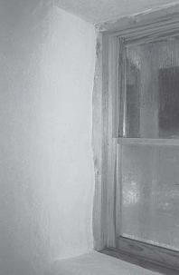
Windows can be finished with an extension jamb and casing, and the plaster butted into the casing.
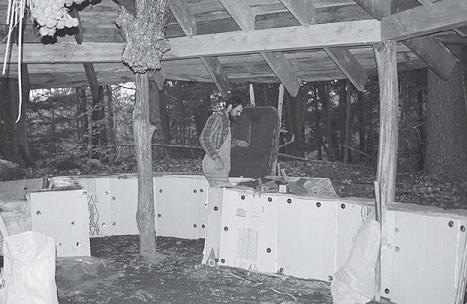
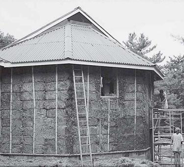
In this case roof- and wall-foundation systems are separate, the roof supported by a pole frame, while the bales sit atop earthbags. The bale walls are allowed to “wander” in relation to the frame. Lacinski/ Klippenstein roundhouse, Ashfield, Massachusetts.
The “Floating Frame”
No rule demands that the load-bearing columns in a bale-walled building must stand everywhere in the same relationship to the walls. Bales are unique among insulation materials because they are capable of standing upright, on their own, independent of a supporting structure. This opens tremendous possibilities to the designer. Ted Butchart of GreenFire Institute, Winthrop, Washington, has evolved some very original designs, based on the practical idea that structure (in this case, the roof and the columns that support it) and walls can be allowed to join or separate in different areas of the building, to maximize the potential of each.
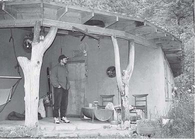
In his design for Nancy Simmerman’s house on Lummi Island, Washington, Ted employed a slightly different system in each of the four main walls. The south, with its large windows, is stick framed, and includes no bales. The north, east, and west are framed in a post-and-beam system, but the 4-by-4 posts, in each, stand in a different relationship to the walls. On the east, the columns are buried within the walls. To the north, the posts are held 3 feet out from the wall, creating a substantial overhang to protect the wall from the prevailing weather. (When Paul visited, the north soffit was hung with dozens of bunches of drying flowers and herbs. Nancy is a brilliant gardener.) To the west, the gable-end roof and supporting columns are carried out 14 feet, to shelter an outdoor sitting area from the coastal Northwest drizzle.
Looking at the roof and interior floor of this house in plan view, you realize that they are two separate units, one superimposed over the other. Excepting the fact that the roof must be kept, in all directions, larger than the area enclosed by the walls, there are few limitations on the variety of indoor and outdoor spaces that can be economically enclosed using such a system. Ted also employed a creative variation on this idea on the Thrune massage studio. (See the Thrune profile following chapter 12).
Here the bale wall extends in alongside the front door, creating a covered entryway. Miner/Stromberg home, Darby, Montana.
Stick Frame and Bale Walls
Stick-framed structures and bale walls are highly compatible; it is surprising that so few buildings have been designed this way, to this point. We think the reasons are primarily emotional. First of all, people are in the habit of thinking of bales as a masonry material, as blocks to be stacked. Using them individually between framing members requires a departure from this mind-set. Second, stick framing is just not alternative enough for a lot of people. The boiled-down, mainstream stick-and-sheet industry is what is wrong with our buildings, right?
Five advantages proceed from the idea of using a stick-frame structure with bales as insulation. First, similar to any other framed structure, is the fact that you have a roof over your head before starting to play around with bales. The second advantage is the presence of abundant nailers wherever needed for openings, cabinets, siding, bracing, and so on. Carpenters (the people responsible for most construction) love this, because it’s what they’re used to, and it’s what these other components are designed to mount to. As a third benefit, stick framing is one of the most conventional and cheapest forms of construction available in areas where wood is an abundant resource, as is the case in many northern countries. The technique is well known, and trained carpenters or moderately skilled owner-builders can raise a complete structure (including the roof! ) quickly, so that they can then concentrate on the real thing everyone’s been dreaming of: the bale work! Building inspectors also like the fact that stick framing is standard; at worst they are likely to regard the bale component only as a bit eccentric.
The north and west walls of this house are extended, to shelter the building and create an outdoor sitting area. Simmerman home, Lummi Island, Washington.
The fourth advantage comes with the spacing of the studs. Because of building code requirements, the maximum allowed spacing of studs for snow-load conditions is relatively narrow, which works well with placing single bales, stuck between framing members. A fifth benefit is the numerous ways the bales can be tied to the frame; they can be stitched to the studs with twine, pinned by several methods, wrapped with strapping, or even fastened with hardware. All of these techniques, alone or in combination, will also add some stiffness to the structure. Bales can be stacked either inside, outside, or between framing members.
Bales Inside Frame
Bales inside a stick frame can be the ideal system for a house that is to receive wood siding, because the required nailers are already present. The frame would be stood first, and the roof installed. The frame might be sheathed on the inside with plywood, or preferably braced with the T-shaped device called “Windbrace” nailed across the studs’ faces, the T pointing away from the wall so that no kerfing is required on the stud and bale surfaces. This allows the bale to receive at least one rough coat of plaster on their exterior, as a protection against fire and rodents, and to maximize Rvalue (see “Siding,” in chapter 9).

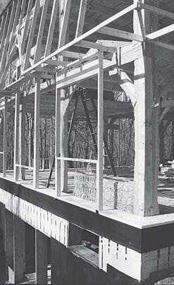
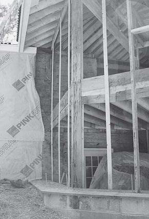
Well-planned stick framing can use very little wood.Gary Seldon’s design employs a beefed-up band joist as window header, allowing single-stud construction all along the wall, greatly sim-plifying bale notching.Gould/Crevier home, Leverett, Massachusetts.
The bales would be stacked against the interior of the frame, and tied periodically to the studs. A rough coat of plaster would then be blown onto the exterior surface of the bales, windows and doors would be installed into their conventionally framed openings, and the wall would be ready for siding. It would be possible to ventilate this wall cavity, essentially creating a ventilated rainscreen cladding system (see chapter 9, “Selecting Finishes” for more details on rainscreens).
This system has only one major drawback: the bales take up what, in a conventional building, would be usable floor space. In reality, of course, this is always the case with bale walls; their depth means that the design must include an extra band of floor area, out beyond what would be required if the wall were only 4 or 6 inches thick. This fact seems particularly obvious in the stick-framing case, since the bale wall is being built entirely within the space enclosed by a standard structural system. We think that to focus too intently on this fact is to fall into that old consumer trap of placing quantity before quality. Who would not gladly choose a smaller, more vibrant bale-walled space over a larger, thin-walled box of sheetrock, anyday? The fact remains, however, that integrating the bales into the frame is often a better choice, to preserve the maximum amount of floor space.
Bales Outside Frame
In this technique, a bale wall is built as a wrap around a conventional stud wall, on its exterior plane. An objection to this system could be made on the aesthetic grounds mentioned above. What would be the point of placing bales outside a sheetrock wall?
Technically speaking, however, this method does have some merits. Wires and plumbing can be run within the stud-wall cavity, and a polyethylene air/vapor barrier can be placed behind the drywall. Such features would ease the minds of many designers, builders, and code officials.
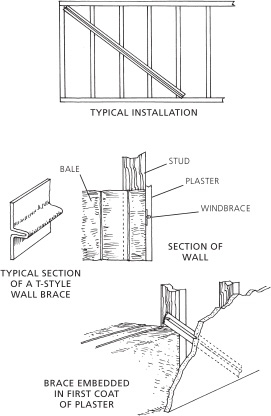
Providing extra lateral support with a T-style metal wind brace.
If the interior walls of the house were to be paneled with wood, this system might prove quite practical. The contrast between interior wood and exterior plaster, a reversal of the usual configuration, could be quite interesting.
Bales between Framing Members
People have experimented with inserting bales between studs in various ways with fairly good success. This seems to be the most promising variation on stick/bale construction. Because stud spacing can be varied to accommodate different designs and environments, the bales can be positioned in many ways. To fully understand these we have to review the nomenclature of a bale: A regular bale laid flat has a bottom and a top (the two string sdes), two edges, and two ends. For any type of bale, the length is measured from end to end, its width from edge to edge, and its thick-ness from bottom to top. While length regularly varies 6 to 10 inches within a shipment of bales, the two dimensions that remain constant with any type of bale are the width and the thickness. Because studs are usually spaced quite closely, typically between 16 and 24 inches apart, these narrower di-mensions are the best suited to fit between studs. This means turning the bales up on their ends. Knowing that the Rvalue per inch of a bale is higher across the grain (through its thickness, rather than its width), we often find it beneficial, in terms of saving floor space, to place the bales such that their narrower, thickness dimension is in the wall. Bearing this in mind, we find several ways of inserting the bales between the studs.
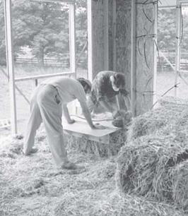
People have experimented with inserting bales between studs in various ways with fairly good success.
UNADULTERATED BALES
The first option, which requires the least prep work, is to snug unmodified bales tight between the studs. Stud spacing would depend on whether two- or three-string bales are used, and on the orientation of the bales. Studs are placed so that the thickness, or more likely the width, of the bale will fit exactly between them. Thus, a two-string bale that is to be set on its end and so that its strings are exposed on the face of the wall will need an 18-inch space between the studs, which means a framing layout of 19 1/2 or 20 inches on center, depending on whether planed or truedimension stock is used. If thicker stud material is used and the top plate beefed up into a light-weight beam, the bales could even be laid hori-zontally, either on their edge or flat.
This technique is fast, doesn’t require any notching of the bales, and allows the studs to be positioned wherever most appropriate in the section of the wall. Studs placed flush with (or, more likely, 1 to 2 inches proud of) the exterior plane of the bales would provide nailers for siding; held to the interior they would work for fastening drywall or paneling. They could also be hidden anywhere inside the section of the wall, leaving the two bale surfaces available for a plaster finish.
The main drawback of this method is the need to stuff the vertical cavities left between the stacks of bales. This stuffing needs to be done very carefully in order to maintain the full integrity of the wall. It must be made to achieve a compaction and insulation value comparable to that of the bales. If the plaster is to be applied directly over the straw, without reinforcing, then the stuffing must also be capable of supporting this material. The ideal stuffing is probably a very light straw-clay mixture, but densely packed straw flakes, possibly covered with some netting material, would also work well in most situations.
MODIFIED BALES
The next options involve notching the bales for stud insertion. The main advantage of this method is that it dramatically reduces the need for stuffing, because any cavities left between bales and framing will be small. Placing the bales on their edge is impossible, in this case, because the strings would interfere with the notching. Laying them flat is annoying because each bale usually has to be measured and marked before it can be notched, and the strings sometimes still end up in the way of the cuts. In this case it usually makes the most sense to place the bales in an upright position, on their end, with the strings showing on the face of the wall. This leaves ample room both for notching at the edges of the bale and for rounding or beveling at the window openings.
Notches can be made on one or both sides of each bale. This decision depends on the design and on the attachment system, but as a general rule one notch per bale means a cleaner job with half the work, and less time spent squinting and coughing through a haze of straw dust.
Unless someone can be very accurate at eyeballing regular cuts with a power tool, a jig should be used to cut precise notches. The process of mating the bales with the studs is difficult enough, without notches that are too fat in some places and too thin in others. Obviously, it is crucial that the framing be laid out on a very regular pattern, and that doubled-up studs be avoided, wherever possible. This is not a framing plan for those who are content to copy their details out of books of standards. It should be possible for the great majority of the bales to be notched on the same pattern, without any form of measurement. Some corner bales will require a second notch, to accept studs on two faces. Bales at windows might require custom treatments as well, though it is far better if window openings can be made to correspond to the larger framing cadence.
At the Gould/Crevier house, where Gary Seldon allowed the bale dimension to completely rule the framing layout, bale insertion was still difficult. Because the notches were cut with an oversized circular saw to exactly the 1 1/2-inch width of the studs, each bale usually needed to be pounded quite forcefully, to be able to slide between its neighboring bale and its let-in stud. This problem tended to increase as the builders progressed down the wall. It was also inevitably compounded by bowed framing members; in fact, these may have been the source of most of the trouble. Considering this experience, it seems prudent to oversize the notches by a small mar-gin, say 1/2 inch, to allow some breathing room during the insertion process. This would be less necessary in the first few columns of bales in any given wall, which tended to go in easily. Because the gap created would only be as deep as the framing member, typically 3 1/2 or 4 inches, it could be filled with a straw-rich lime or clay plaster. This would be much easier work than the pounding that was required to install most of the perfectly notched bales. The substantial compressive strength of such plasters would ensure that the bales and studs would ultimately be pressed tightly together. As an added bonus, the resulting ribs of plaster would anchor the finish very securely to the bale substrate.
Notching a bale with an oversized circular saw and jig. Note the single-stud framing at all locations.
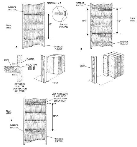
Notching options. A) One-edge notch for position-ing studs either toward the interior or exterior of the bales. B) One-edge notch for positioning studs in the center of the bales (gaps are filled with loose straw, straw-clay, or rigid insulation. C) No notching, for positioning studs anywhere.
In most cases, notching will occur at the corner between the edge and the face of the bale, because the framing will be held at either the inside or the outside face. This is easier than cutting a groove down the center of a bale surface; it also leaves the wood available as an attachment point for all manner of other building components. It is possible, however, to conceal the studs anywhere within the wall. Gabe Prost of Ladysmith, Quebec, built his house with such a system. Gabe’s is a 2-by-6 frame with studs spaced at 19 inches on center. Using an angle grinder fitted with the Lancelot chain saw wheel, he made a 6-inchwide running kerf down the middle of each edge side of his bales, and then forced them between the studs, such that the studs keyed into the wide grooves. Some stuff-ing was needed to fill a few gaps, due to the irregularies of the bales. The main drawback of this method is that additional framing was needed to accommodate cabinets and other similar items. (See profile, “The Bourke House,” in chapter 3.)
Steel and Concrete Frames
Although it is not yet a trend in the bale world, steel framing is considered by many people to be a valuable alternative to wood framing, and a few projects have been built with steel frames. Without getting into a detailed evaluation of the ecological and economic factors of using steel, it is worth mentioning some of the particularities of the straw-steel relationship.
First and probably worst of all is that working with steel usually means using torches, or power tools that throw off a great deal of sparks. Neither of these can be recommended on a site where piles of bales or loose straw are ready to catch fire. In the arid West, where the moisture content of bales is typically very low, a couple of disastrous mistakes have resulted from the use of torches around straw. If you’re going to head down this road, you should schedule all possible metal cutting before the bales go in or after they are plastered. If any steel work must be done in the interim, the bales must be carefully protected, and any loose straw must be removed from the building. (This is a good idea in any case, of course.) You could also spray your walls with a fire-retardant mixture made of Borax and boric acid (see the sidebar “Recipe and Example of the Borax Application and Results” in the Sivananda profile, which follows chapter 8).
As far as owner-builders are concerned, steel is certainly not as user-friendly a material as wood. With occasional or inexperienced volunteer help, the risk of injuries can also become very real. Workers who are experienced with the material and the tools involved are not always available, and because they tend to work in the commercial construction industry, their time may be unaffordable.
In cold-climate construction, the major potential drawback of steel is the risk of condensation, if the details of the relationship between steel and straw are not carefully worked out. This should not be too difficult n the walls—steel framing should be held either inside the living space, as in a bale wrap around a heavy steel frame, or to the inside portion of the bale wall, as in a steel 2-by-4 stud system let in to the inner 3 1/2 inches of the bale wall. Obviously, no steel members should span from inside to outside; the detailing could get tricky at the windows. Roof details might also be difficult, because roof framing has no choice but to span from the ceiling or attic to the outdoors.
A
French
Farmer’s
Hint
Thierry Baffou and Catherine Dubourg, who paid a visit to Quebec straw-balers after a one-year world tour of straw bale structures, taught us about a very interesting peculiarity that makes bales somewhat self-protective from rain when stacked in a certain position.
A close look at a bale is all we need to understand this characteristic. In fact, we can quite easily notice that the tips of the fibers are all oriented in the same direction, as if every surface of the bale were combed in the same fashion. This is due to the baling process. In the machine, loose straw is packed inside a closed chamber into flakes that are all equally compressed in the same fashion; these are tied together and then pushed along a tray to the exterior. Every step of this process forces the fibers to slightly bend in the same direction. With clean bales this is visually pretty obvious.
On some types of bales with fluffy surfaces, this has to be checked in a different way; the trick is to rub a hand on the bale surface, lengthwise: you get either a smooth or a scratchy feeling, which tells you exactly the orientation of the fibers. Like on a thatched roof, the orientation determines how water can be shed away.
In their native Bretagne, Thierry, Catherine, and most of the other farmers traditionally stack their bales in the fields with this notion in mind. They make bundles with six or seven bales sitting back-to-back in an upright position, making sure the fibers are oriented downward. Each bale is patted, as a check. Piled in this fashion the bales can stay in the field for days under pouring rain without any major damage to the straw.
This knowledge could also assist in the placing of bales in your walls. If the design is made for bales to be placed upright between studs, for instance, the Breton fashion could make your bales equally self-protected until the roof and/or the plaster goes on. Even after the house is completely finished, the bales would still be protected from water infiltrating behind the plaster.
You will also find that this positioning is quite beneficial if you’re plastering directly onto the bales. If, like most people’s, your plastering technique is an upward movement of the trowel, having the bales stacked in this fashion will make the fiber tips tuck up under the pressure of the trowel, while letting the plaster snug into thousands of small niches. Applied on bales turned in the other direction, the plaster is thrown back at you, as the thousands of tips are pressed down under the pressure and then swing back up when released, like miniature catapults!
The tips of the fibers are generally all oriented in the same direction on the surface of the bale.
Reinforced concrete framing is an option as well. As with steel, some insulation and condensation issues are relevant, but these can be solved in a straightforward manner with exterior insulation of the concrete structure. In areas where wood is plentiful, it is certainly preferable to concrete, from an ecological point of view. For large buildings in cold dryland regions (where size, rather than weather, might make Nebraska-style construction impractical), concrete framing might be the way to go.
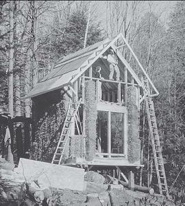
Retrofitting an existing structure by snugging bales between the 2-by-6 studs and extending roof overhangs to protect the straw. April Heaslip home, Bellows Falls, Vermont.
Retrofits
Retrofitting and remodeling comprise an even larger component of the building industry than new construction. This makes ecological sense. Remodeling is also a key to maintaining the fabric and character of our communities.
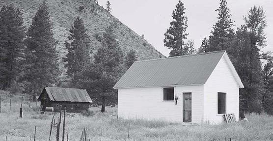
An old hospital building was delivered to this site on a flatbed truck, then one room was outfitted with bales to create climate-controlled conditions for seed storage. Winthrop, Washington.
A New
Life for an
Old Stud
Frame
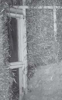
Beginning to plaster interior walls.
Let’s say your old house has a conventional stud frame and the interior finishes are in good shape, but the old sawdust has settled a bit in the wall cavities (or the walls never had any insulation at all) and the exterior siding needs a serious face-lift. Air leaks through the walls make the place impossible to heat, and drafts make you sneeze all winter long. So you figure it’s time to do something about it.
You first remove the siding, then the sawdust, and sort out the salvageable siding, storing it for reinstallation. You then fur out the existing floor platform by 19 inches (18 inches for the bale extension and 1 inch for the plaster) and build new overhang extensions to accommodate the extra thickness of the walls and provide valuable rain protection. Then, from the platform up, you start nesting bales against the interior drywall. Finally, you fill the vertical cavities facing the studs, between the stacks of bales. The bale wall is now ready for finishing.
You have two sets of finishing options: You could reinstall the old siding, with necessary repairs and replacements, or put on a brandnew one; in either case you’ll have to add nailers on the exterior plane of the bale wall. The other option would be to finish your wall with plaster and get the real bale look that you’ve been wanting without really believing it was ever possible!
The main drawbacks of this method are the overhang and floor extensions that you’ll have to build. Otherwise, if you can afford to lose the required interior floor space and you don’t want to fiddle with the overhangs and platform extensions, you’re well advised to consider retrofitting from the interior. You will then have a great opportunity to get rid of that boring drywall and preserve the original exterior look of your house, which, after all, was what you had fallen in love with when you bought the place. The other advantage here is that you will be working in total protection from the weather.
A final option is also possible if both exterior and interior finishes are in too bad a shape to be salvageable, and if you also want to add more windows or make other renovations. If the frame is in good condition, then you can strip it bare naked and fill it with bales in any of the options described before. Compared with new construction, you will have certainly saved substantially on framing and roofing while having the opportunity to do most of the work protected from the rain.
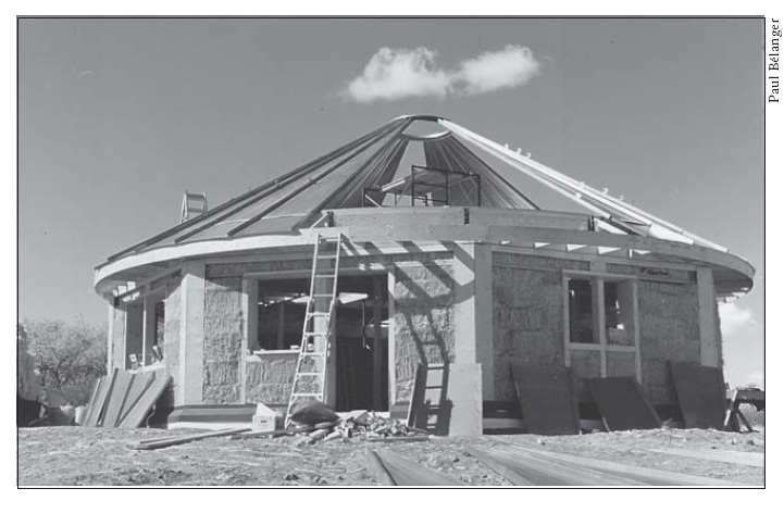
Paul Bélanger of Living Design Systems has developed an efficient way to make octagonal buildings by using eight prefab columns to support the roof beams. Bales are stacked between the columns then plastered. The roofs are conical steel caps usually used on grain silos. Also note the modular windows.
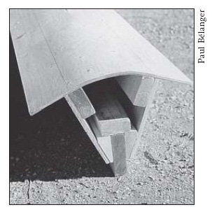
Detail of the Bélanger column made of 3/8-inch plywood and regular 2-by stock. Curving the plywood is too difficult, and the plywood had to be cut anyway so the column would have a slot in front. It’s far easier to use 1/4-inch plywood in two sections.
Considering that one of the main reasons for retrofitting an old building in a northern climate is to improve the quality of the insulation, a bale retrofit becomes an interesting option for almost any kind of structure, providing the additional floor and roof space required by the bale walls is available or can be added at a reasonable cost.
It is possible to retrofit many types of buildings with bales; this usually happens by wrapping the bales around the outside, or, in the case of a barn, by stacking them inside the existing boards, with a supplementary backplaster already installed.
Stick-frame structures are probably the best suited for retrofit. We find that a two-string bale placed on its end such that the strings are hidden in the wall (and the wall is 18 inches thick) fits quite nicely between 2-by-4s conventionally spaced at 16 inches on center. If either one or both sides of the wall can be stripped down and refilled with bales, this can work perfectly.
Framed structures offer many advantages for bale builders. They dra-matically increase the range of available design options, while allow-ing for a slower construction process, and protection from the elements, during this process. In areas where trees are a native resource, it usually makes sense to use them (or concrete, or steel) to support the roof of a bale-walled building.
1 . Brand, How Buildings Learn, p. 120 .
2 . David Riley, Gregory MacRaw, and Juan Carlos Ramirez, “Strength Testing of Stucco and Plaster Veneered Straw-Bale Walls,” The Last Straw, 24 (winter 1998): p. 8–9.