Chapter 8. Bot Control
At this point in the build, after we hook up the motors and connect the motor controller to the Pi, we could remotely log into the rover and control it from a laptop. If you were to add a battery for the Pi and at least one for the motors, the rover would be technically ready to test outside. But don’t do that yet. It might behoove us to connect everything first, debug the inevitable wire crossings and incorrect hookups, and then take it outside.
Connecting the Motors and Motor Controller
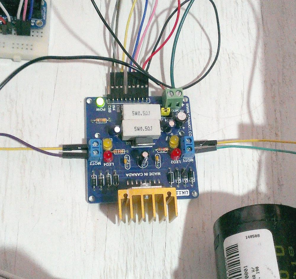
Setting the sensor connections and the robotic arm aside for a moment, let’s go through the process of hooking up the motors so we can test the movement. You’ll need to set aside six GPIO pins for the motor controller—three for each motor. I used pins 19, 21, 22, 23, 24, and 26, simply because they’re six GPIO pins that are located close to each other, physically. I connected pins 19, 21, and 23 to the IN1, ENA, and IN2 inputs, respectively, and pins 22, 24, and 26 to the IN3, ENB, and IN4 inputs. As a reminder, each motor uses three pins: two input pins (labeled IN1 and IN2) and one enable pin (labeled ENA and ENB). Sending HIGH signals to different combinations of those three pins results in different motor behavior, as you’ll see in Table 8-1. Arguably the most important pin out of the three is the enable pin; if an enable pin is set LOW, that motor doesn’t turn, regardless of what signals are sent to the two input pins.
After you’ve connected the input and enable pins, connect the Pi’s 5V output (pin 2) to the +5V pin on the controller, and the GND pin to the Pi’s GND pin (pin 6). Finally, connect the two leads from the right motor to the board’s two MOT1 connections, and the two leads from the left motor to the MOT2 connections (Figure 8-1).
As I mentioned in the preceding chapter, I also installed a switch between my drive battery and the L298H board, so I don’t need to worry about phantom power drain, or some random signal noise making the motors go nuts. When I’m ready to run the rover, I simply flip the switch and get power to the board.
To control the motors using the L298H board, you enable a motor by setting that motor’s EN pin high. Then you can either spin the motor one way by sending a HIGH signal to one IN pin and a LOW signal to the other, or reverse the signals and make the motor turn the other way. This might be better illustrated by Table 8-1.
ENA Value | ENA = 1 | ENA = 1 | ENA = 1 | ENA = 0 |
IN1 Value | IN1 = 1 | IN1 = 0 | IN1 = 0 | - |
IN2 Value | IN2 = 0 | IN2 = 1 | IN2 = 0 | - |
Result | Motor spins CW | Motor spins CCW | Motor stops | Motor stops |
When you read “Motor stops,” you can read that as “Motor screeches to a halt.” In other words, there is no coasting here; when a motor stops, it stops.
Because we’re using the RPi.GPIO library, it’s a simple matter for us to send pins HIGH or LOW by using these commands:
GPIO.setup(PinNumber,GPIO.OUT)GPIO.output(PinNumber,True)GPIO.output(PinNumber,False)
If we do this based on input from us (the user), we can control the motors with an interactive Python script.
Once you’ve connected the motors and power, it’s a good idea to get the rear tires off the ground so you can test different commands without having your rover run away from you. Because the rover is not moving, this setup also has the advantage that nothing has to be portable; you can just plug in your Pi and use an AC adapter (if you have one of the right size) for your motors. Only after you fix the bugs in your code (oh yes, there will be bugs) do you need to plug in batteries and run around after the rover as it goes all sorts of places you never intended. For now, think of it as having your rover up on the rack in the garage. Remember, you’ll be hooking the L298H board to your Pi’s pins as follows:
- IN1 → pin 19
- ENA → pin 21
- IN2 → pin 23
- IN3 → pin 22
- ENB → pin 24
- IN4 → pin 26
With the drive wheels elevated, start a new Python script called motortest.py:
importRPi.GPIOasGPIOimporttimeGPIO.setwarnings(False)GPIO.setmode(GPIO.BOARD)#19 = IN1#21 = ENA#23 = IN2GPIO.setup(19,GPIO.OUT)GPIO.setup(21,GPIO.OUT)GPIO.setup(23,GPIO.OUT)#22 = IN3#24 = ENB#26 = IN4GPIO.setup(22,GPIO.OUT)GPIO.setup(24,GPIO.OUT)GPIO.setup(26,GPIO.OUT)defrForward():"R motor forward"GPIO.output(21,1)GPIO.output(19,0)GPIO.output(23,1)deflForward():"L motor forward"GPIO.output(24,1)GPIO.output(22,0)GPIO.output(26,1)defrBackward():"R motor backward"GPIO.output(21,1)GPIO.output(19,1)GPIO.output(23,0)defLBackward():"L motor backward"GPIO.output(24,1)GPIO.output(22,1)GPIO.output(26,0)defallStop():GPIO.output(21,0)GPIO.output(24,0)rForward()lForward()time.sleep(2)allStop()time.sleep(0.5)rBackward()lBackward()time.sleep(2)allStop()
You can experiment with other sequences, of course, but running this simple script with
sudo python motortest.py
should result in your wheels going forward for 2 seconds, pausing, and then going backward for 2 seconds. Play around with other values until you’re familiar with how your motors respond and how you have them hooked up. Again, keep this script, as you’ll be using it in your final code.
Controlling the Robotic Arm
The other bit of code you’ll need in order to control your rover is the code necessary to raise and lower the robotic arm. You may remember it from Chapter 6, but let’s revisit it anyway by writing an interactive script so you can see exactly what values have what effect on your arm.
To keep things simple, you should be in the same folder in which you
installed the ServoBlaster library. (You don’t need to be, but it keeps
everything simple and organized.) Make sure your servod program is running
with sudo ./servod, and connect your servo to pin 12 (GPIO 18) on the Pi. If
you get confused, refer back to Chapter 6, or reread the startup splash
screen for the servod command (Figure 6-3). Now start a new Python
program:
nano servomap.py
Then try entering and running the following program:
fromsubprocessimportcallimporttimewhileTrue:position=raw_input("Enter servo value: ")call("echo 2="+position+" > /dev/servoblaster",shell=True)time.sleep(2)
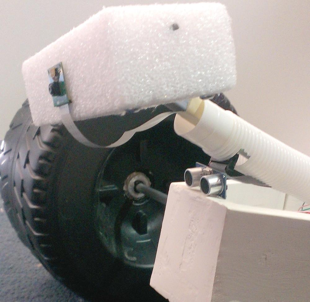
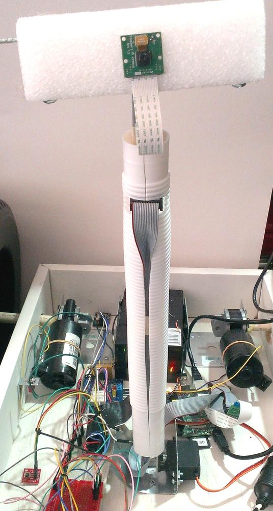
When you run this script, you’ll have the ability to send different servo values to the arm to see where it ends up. Ideally, you’ll probably want the arm to be almost resting on the front of the rover when it’s not deployed, and you’ll want it almost straight up when it’s active (Figures 8-2 and 8-3).
In fact, play with the arm configuration to find the value that allows the arm
to rest on the body of the robot when not in use. Putting the arm at
this rest position will help save your batteries, as otherwise the servo will
continue to draw power to keep the arm in position. When you put the arm into
the rest position and then send a value of 0 to the servo with
echo 2=0 > /dev/servoblaster
it will power off the servo, saving on power.
My arm’s values ended up being 45 at rest, and about 100 when standing at attention. Obviously, your values might differ significantly
depending on your servo, your arm, and how it’s placed in your rover.
Now that you have your values, you need to write raise arm and
lower arm functions to add to your final code. One thing you’ve probably
noticed is the almost violent way the arm shoots from point A to point B. To keep things from breaking on the rover, and to maintain the illusion
of robotic grace (as well as not to poke anyone’s eye out), I wanted to slow
things down a bit. To do that, I wrote a script that iterates slowly through
the intervening values. To wit:
fromsubprocessimportcallimporttimedefraise_arm():foriinrange(45,100):call("echo 2="+str(i)+" > /dev/servoblaster",shell=True)time.sleep(0.5)deflower_arm():foriinreversed(range(45,100)):call("echo 2="+str(i)+" > /dev/servoblaster",shell=True)time.sleep(0.5)
The script is pretty self-explanatory, but basically the raise_arm() function
sends the values from 45 to 100 to the servo, one at a time, with a pause of
half a second between movements. The lower_arm() function does the same thing
in reverse. When you run this, you’ll see your arm slowly raise and lower at a
much more respectable pace—experiment with the time.sleep() values as you
see fit.
Although the rover is a complex piece of machinery (it is a robot, after
all), these two snippets of code are all the basics you need in order to
control it: move forward, move backward, turn left, turn right,
raise arm, and lower arm. In the next chapter, we’ll go over using the GPS
module to help you figure out where the rover is, and then in Chapter 10 we’ll
look at some of the sensor possibilities and how to write code for them.


