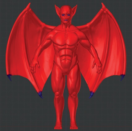
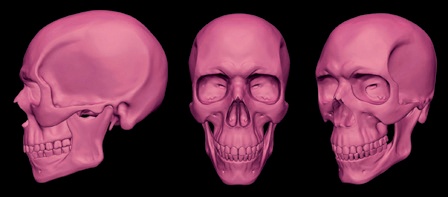
Chapter 6. Sculpting
The addition of sculpting tools to Blender’s arsenal has vastly broadened the range of creations possible and the level of detail we can add to our creations. In addition, sculpting allows for much more freedom in the route taken to create a model; prior to its introduction, we had to labor to create topology to support each element of a model. Now, with sculpting, we can start from a much simpler mesh, use multiresolution subdivision to provide the level of control necessary to support the forms we want, and worry about the topology later.
In this chapter, we’ll introduce Blender’s sculpting tools and show you how to use Sculpt mode. We’ll look at customizing the appearance of Sculpt mode and the tools you can use to get the most out of Blender when sculpting. Then, we’ll move on to using these tools to start sculpting on the base meshes we created in Chapter 4, taking them from simple, low-res base meshes to highly detailed, sculpted models. Finally, we’ll look at some general principles for sculpting.
Sculpt Mode
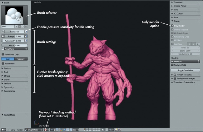
In order to sculpt in Blender, you’ll need to enter Sculpt mode in the 3D Viewport, as shown in Figure 6-1. Once in Sculpt mode, make sure you have the Tool Shelf open (T), as this is where you’ll find all of Blender’s Sculpt mode options and tools.
The familiar Tool Shelf on the left of the Viewport is now home to our Brush options for sculpting, where we can choose between different brushes and adjust their settings. Brush options include the type of brush; whether it will utilize pressure input from a graphics tablet (recommended if you have one); and the size, falloff, and shape of the brush. Figure 6-1 also shows how the 3D Viewport has been set up to make sculpting easier—you use Blender’s GLSL shading and enable Only Render to display only objects that will be rendered. This keeps the grid and any superfluous objects in your scene, such as lamps and cameras, out of your way while sculpting. We will cover these settings in more depth in Customizing the 3D Viewport.
Brush Options
The Brush options are shown at the left of Figure 6-1. Click a selected mesh in the 3D Viewport to begin sculpting.
Running down the list of panels in the Tool Shelf at the left of Figure 6-1 in order (some are collapsed, but their titles are all visible), we have the following:
Brush. Here, you can select which brush to use; the brush properties, such as radius, strength, and autosmooth; whether the brush should add or subtract from the surface; and some options specific to individual brushes. You can also create new brushes from the Brush selector by clicking the + icon. Doing so will duplicate the current brush, creating a copy that you can modify separately.
Texture. This panel allows you to create strokes with unique shapes and textures or to drag out patterns onto the surface of your mesh. Brush textures use the brightness of the texture to determine how strongly to apply the brushstroke. While you can use color images for brushes, it’s more common to simply use black and white textures to make it easier to judge their effects. (In order to distinguish brush textures from other kinds of textures, I’ll often refer to them as alphas.)
Tool. While the brushes in the Brush selector have names like Clay and Smooth, you can change these names as you please. The actual behavior of any brush is determined by the choices you make in the drop-down menu in this panel, which allows you to choose from all of the base tool types Blender has to offer before customizing them further.
Stroke. This panel contains options for how your mouse or tablet strokes are converted into sculpting strokes. The default method for most brushes, Space, creates a uniform brushstroke. Anchored allows you to click and drag out a large stroke over your mesh, centered around the starting point of the stroke and with a radius determined by how far you drag. This option is extremely useful for dragging out textures over the surface of your mesh in order to create surface detail. Another option, Smooth Stroke, causes your strokes to lag behind your cursor as you pull it around, resulting in clean, smooth curves.
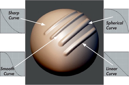
Curve. This panel lets you choose the brush’s falloff curve (see Figure 6-2) and gives you fine control over how the depth of your strokes fades away from the center. You can either define the curve manually by dragging and clicking to move and adding points to the Curve editor, or you can choose one of the presets from the icons below the Curve editor. The default Smooth curve is fine for most brushes, but when dragging out alphas, the flat Max curve is useful. For fine creases, the Sharp curve is best.
Options. This panel contains mainly miscellaneous options. One option is whether to constrain sculpting to individual axes. Another determines whether to keep your brush size and strength universal or to let you set it for each brush. (Maintaining a universal brush size is often less confusing, but it’s usually preferable to choose strength for each brush individually, as you may want different strengths for different tools.)
Symmetry. Just as you would use a Mirror modifier for a normal mesh, you can enable Symmetry when sculpting to keep your brushstrokes symmetrical. This is a useful option for a lot of sculpting as most organic creatures are broadly symmetrical.
Appearance. This panel contains some aesthetic options for changing the color of the brush cursor or adding a custom icon for your brush.
Brush Types
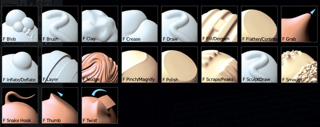
The default brush types, which are found in the Tool panel (see Figure 6-3), are discussed below. Some have hotkeys (in brackets) that allow you to quickly cycle through any brushes of that type that you have created. Almost all brushes (Grab, Nudge, Thumb, and Snake Hook are the only exceptions) also have a Subtractive mode (ALT) that usually does the opposite of what the brush does in Additive mode.
Blob. This brush type creates blob-like inflated lumps in the surface of your mesh. This option is a bit of a mix between the Draw and Inflate brushes. Additive mode builds out, while Subtractive cuts in.
Clay (C). One of the most important brush types, the Clay brush builds up the surface of your mesh evenly, filling valleys first and then building up smoothly from the surface of the mesh. You’ll find this brush type useful throughout the sculpting process, though beware when adding fine details, as it will build up over them (use the Draw brush instead). Additive mode builds out, and Subtractive mode carves into the mesh.
Crease (SHIFT-C). This brush type combines the Draw and Pinch brush types, drawing a stroke out on the mesh and then pinching it to make it tighter. It is most useful in Subtractive mode, where it’s great for creating wrinkles and creases in a character’s skin, but it can also be used in Additive mode to create sharp edges by tracing along the edge of a form.
Draw (D). The Draw brush type draws a stroke out from the surface, moving the surface without changing the details underneath. If you use Draw early on when sculpting large-scale forms, it may make life difficult, as it can result in a rather lumpy look (which is why the Clay brush is more useful). Later on though, when adding fine details, the Draw brush type is very handy.
Fill. This brush type fills in valleys in the surface of the mesh without touching the peaks. It is useful for smoothing out and filling in concave areas in a mesh without affecting the surrounding areas. Subtractive mode deepens the valleys instead of filling them in.
Flatten. The Flatten brush combines the Fill and Scrape brush types, filling in valleys and scraping away peaks to create a smoother surface. Unlike the Smooth brush type, this brush flattens the surface in addition to smoothing it. In Subtractive mode, this brush type exaggerates the valleys and peaks instead of flattening them.
Grab (G). This brush type grabs the area under the brush and lets you pull it around. You’ll find this to be a very useful brush type.
Inflate (I). The Inflate brush type inflates the mesh in much the same way the Shrink/Fatten operator does in Edit mode. Inflate is useful for establishing volumes and is sometimes a good alternative to the Draw or Clay brushes, but be sure to keep the strength of this brush low or it can do some damage. Also, be aware that in addition to pushing the surface outward (or inward), this brush usually makes faces bigger, reducing the amount of detail that the modified area can support. In Subtractive mode, this brush shrinks the mesh instead, often causing the mesh to self-intersect. Use it carefully.
Layer (L). This brush type builds out an even layer from the surface of your mesh or subtracts an even layer in Subtractive mode.
Nudge. Like the Grab brush type, this brush type only nudges the mesh a small distance, and you can keep moving your cursor around to other areas to nudge them as well.
Pinch (P). This brush type pulls faces under the brush closer together, creating a pinching effect. This brush is useful for tightening creases and wrinkles or for sharpening edges between forms on hard-surface sculpts. In Subtractive mode, this brush pushes the faces farther apart.
Rotate. This brush type rotates the area under the brush around the mesh’s origin. I find this pretty useless as a brush type.
Scrape. The Scrape brush type scrapes away the peaks of a mesh without touching the valleys. This brush type is really useful for establishing planes, eliminating lumps and bumps, and smoothing transitions between overlapping forms. Subtractive mode builds the peaks up rather than scraping them down.
Snake Hook. This brush type allows you to pull out a tentacle-like surface from your mesh. Use this brush type sparingly because the topology underneath will probably not support it too well. This option is good for pulling out peaks to look like strands of hair or horns, especially if you plan on correcting the ugly topology later.
Thumb. The Thumb brush type slides the surface of the mesh around under the brush but only on the plane of the direction the surface is facing. This is similar to the Grab brush, except that it allows you only to shift the surface of the mesh around rather than letting you push or pull the surface of the mesh outward or inward.
All of the brushes in Blender’s Brush panel (see Figure 6-4) are just variations on the types listed above, with various tweaks to give each brush slightly different effects. For example, the Polish brush is a variation on the Flatten brush with the Autosmooth setting (which adds a smoothing effect to any brushstroke) turned up.
Creating Custom Brushes
Now that we’ve taken a look at some of Blender’s built-in brushes, let’s look at how to create custom ones to better suit our needs. As explained earlier, Blender’s sculpting brushes are all variations on the same initial set of brush types; the differences come from changing the settings that affect how these brushes function. You’ll want to change some settings frequently, like the radius of the brush and its strength. If you end up using a certain set of brush settings often, it’s a good idea just to give them their own brush.
To create a new sculpting brush, select an existing one similar to the one you want to create, and then press the + icon in the Brush selector next to its name to create a new, unique brush. Now, modify the new brush by changing its strength, assigning textures and stroke options, and so on.
To demonstrate, let’s create a few custom brushes that will come in handy when sculpting.
Clay Tubes
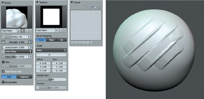
The Clay Tubes brush (see Figure 6-5) will be great for sculpting early on. It works the way traditional clay sculptors work by adding strips of clay to the surface of a sculpture to build up forms. To create a brush that mimics this technique in Blender, take the following steps:
Duplicate the default Clay brush.
In the Texture panel, add a new texture to use as an alpha for the brush by clicking the + icon in the Texture selector. This creates a new texture and assigns it to the brush. Name it something useful, like Clay Tubes.
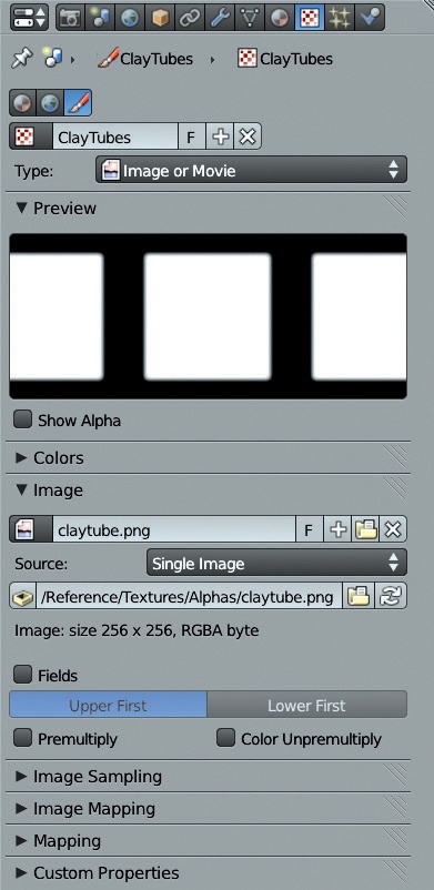
To edit this texture, open the Texture tab of the Properties editor (see Figure 6-6), and make sure you have the brush icon selected to edit brush textures.
In the Type drop-down menu, choose Image or Movie and then select an image to use as a brush texture by opening or adding an image from the Image panel. For this brush, I created a very simple, slightly blurred white square on a black background in GIMP, which I then loaded as the brush texture.
With the texture loaded, return to the 3D Viewport Tool Shelf, and set the brush angle setting (in the Texture panel of the Tool Shelf, as shown in Figure 6-5) to Rake to make the alpha rotate to match the direction of the stroke. Now we’ll have nice square strokes with a slight texture that will be great for building up forms like muscles and wrinkles and for quickly blocking in large shapes.
To stop the usual falloff of the brush, set the falloff curve to the flat Max preset in the Curve panel.
Rake
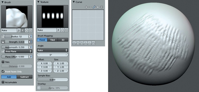
Like the Clay Tubes brush, the Rake brush (see Figure 6-7) is based on traditional sculpting. Clay sculptors often use a toothed scraping tool, a rake, to scrape away at the clay surface to produce a fine texture and smooth forms. In Blender, the Rake brush is great in both Additive and Subtractive modes.
Like the Clay Tubes brush, the Rake brush starts out by duplicating the default Clay brush and then adding a custom alpha, though this time we use a line of blurred dots or squares, as shown in Figure 6-7. To create the Rake brush, take the following steps:
Duplicate the Clay brush as you did for the Clay Tubes brush above.
Add a texture to the brush, as you did for the Clay Tubes brush. See Figure 6-7 for the kind of texture needed.
Set the angle to (surprise!) Rake, and enable Autosmooth in the Brush panel of the 3D Viewport Tool Shelf, setting its value to about 0.25. (This adds some smoothing to the brushstrokes to keep the texture from getting out of control.)
Set the falloff of the brush to flat (Figure 6-7).
Scrape Flat
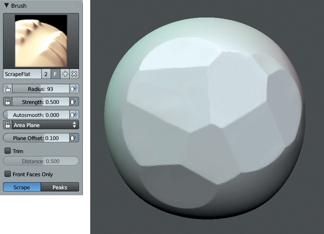
The Scrape Flat brush (see Figure 6-8) creates nice flat, faceted surfaces in a mesh. It’s great for sculpting jagged rocks and hard, technical surfaces and for quickly establishing clear planes in organic models that you can smooth and refine later.
To create this brush, do the following:
Duplicate the Scrape brush.
Lock the Area Plane of the new brush by clicking the padlock icon next to its option (as shown in Figure 6-8). Now, the surface normal of the surface under the brush when you first begin the stroke will be extended throughout the whole stroke, producing a nice flat surface.
Set the brush’s Plane Offset to around 0.1 (see Figure 6-8) to make the brush cut more deeply into the surface. This setting determines how deeply the brush affects the surface for positive values or raises its effects away from the surface for negative values.
Try changing the tool type for this brush to the Flatten, Fill, or Clay tools, as they work well with these settings, too.
Crease Lazy
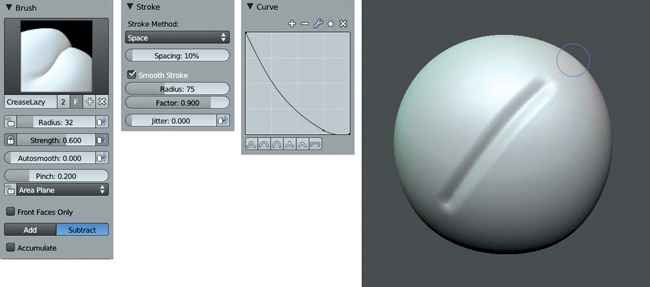
This brush is a variation of the standard Crease brush. With the Smooth Stroke setting activated, the Crease Lazy brush is good for creating long, smooth creases. To create the Crease Lazy brush, as shown in Figure 6-9, follow these steps:
Duplicate the Crease brush and turn on Smooth Stroke.
For both this and the regular Crease brush, I like to turn up the strength of the brush to between 0.6 and full strength and turn the pinch value down to around 0.1 or 0.2. (I find the default pinch strength a bit heavy.)
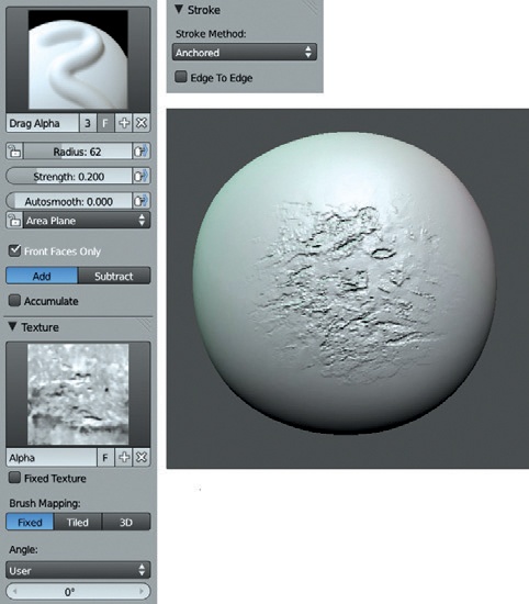
Drag Alpha
The Drag Alpha brush uses the anchored stroke setting to drag alphas over the surface of a mesh, but otherwise it’s just a basic Draw brush. You can create this brush, shown in Figure 6-10, by taking the following steps:
Duplicate the Draw brush and add a texture. Most any texture will work; I chose a rocky image.
Because you can use all sorts of textures with this brush, different falloff curves are useful. For images with a natural built-in falloff to them, like the Clay Tubes and Rake textures (that are black around the edges), you can set the curve to Flat. For textures that you’ve created from photos or other images that don’t have natural falloff (the pattern covers the whole image), use one of the preset curves. A preset curve creates a nice transition so that the alpha won’t produce an obvious edge when drawn out over your mesh.
Making Brushes Available by Default
In order to load your custom brushes by default, you need to include them with your default .blend file, the file that loads up every time Blender starts. To do this, create a new .blend file, create (or append) any brushes you want to make available by default, and then save the modified file (File▸Save User Settings). To append into an existing brush, choose File▸Append (or SHIFT-F1); then select the .blend file where you created your brushes, select Brushes, choose the brushes you want, and click Append. Now your custom brushes will be available whenever you want to sculpt.
Improving Your Sculpting Experience
To get the best from Sculpt mode, you need to tweak Blender’s settings a bit. The goals are twofold: to ensure that you get the best performance while sculpting and to configure Blender’s 3D Viewport and materials to make it easier to see the effects of your brushstrokes on your model while sculpting.
Optimizing Sculpting Performance
Of course, the best way to improve sculpting performance is to use a powerful computer with a lot of RAM. At minimum, you’ll need 4GB of RAM if you plan on going into the millions of polys, but more certainly won’t hurt. But barring hardware upgrades, here’s how to make the most of what you have.
Close other programs. If you’re rendering in another instance of Blender or burning a DVD at the same time, your sculpting performance will suffer!
Enable VBOs (Vertex Buffer Objects). Open Blender’s User Preferences (File▸User Preferences or CTRL-ALT-U), go to the System tab, and select the VBOs checkbox. This will boost the performance of the 3D Viewport if your graphics card supports VBOs.
Turn on Fast Navigate. You’ll find Fast Navigate in the 3D Viewport Tool Shelf under Options. Fast Navigate causes your model to switch back to a lower subdivision level when you move or rotate the 3D Viewport, speeding up navigation while sculpting.
Subdivide before adding a Multires modifier. If you are working from a reasonably dense base mesh, like the ones we created in Chapter 4, you don’t need to perform this step. However, if you intend to start from a cube, add and apply a Subsurf modifier before adding a Multires modifier to speed up sculpting.
This works because, under the hood, Blender looks at how much of the mesh it needs to update based on how many faces of the underlying base mesh were covered by the brushstroke. For example, if your base mesh is only six faces, most strokes will affect a large percentage of faces in the base mesh (at least one-sixth), making it slower for Blender to update its shape. By subdividing first, each stroke will affect a much smaller percentage of faces in the base mesh, so there is less for Blender to update on screen, speeding up you sculpting experience.
Customizing the 3D Viewport
When sculpting, we generally want to see only what we’re working on, without distractions like lamps and the grid floor. To turn off these distractions, open the Properties region in the 3D Viewport (N) and, in the Display panel, check Only Render to show only meshes and other objects at render time. You can also turn off the grid floor and axes guidelines from this panel so that they won’t be visible even with Only Render turned off. With Only Render turned on, the background color for the 3D view switches to the background color set in the World Settings tab of the Properties editor. It can be nice when sculpting to set this to a dark gray or black, but use whatever you like.
MatCap Materials
While sculpting, you’ll want the look of your mesh in the 3D Viewport to give you as much information as possible about the shape of the surface you are working on. While Blender’s open GL shaders do a reasonable job of this (and can be improved for sculpting, as outlined below), using a GLSL material known as a MatCap (short for Material Capture) that shades your mesh depending on its normals gives a better and more aesthetically pleasing view of your models.
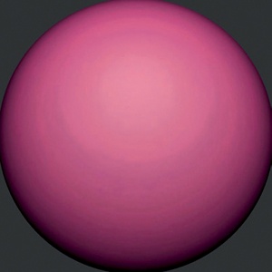
MatCap images use a pre-rendered (or painted/photographed) image of a sphere to shade your whole object, matching the shading of the sphere image with the normals of your mesh. The MatCap image used for many of the figures in this chapter is shown in Figure 6-11. I’ll cover creating materials in Chapter 12, but I’ll outline how to create a MatCap material now.
Creating a MatCap Material
To create a MatCap material, do the following:
Select the object you want to apply the material to.
In the Materials tab of the Properties editor, add a new material by clicking the +New button. This will create a new material with the default settings.
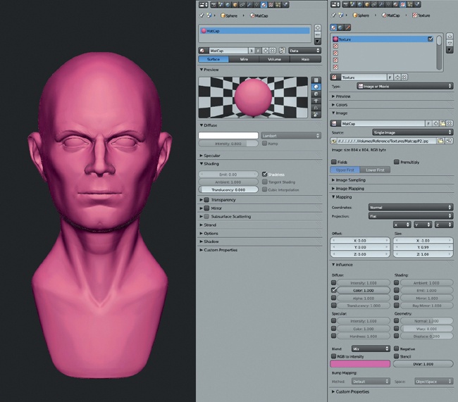
The only modification you need to make to this is to turn on Shadeless in the Shading panel. This stops the material from using lights in GLSL mode and instead only uses color information from the material’s textures. (The relevant settings are shown in Figure 6-12.)
In the Textures tab, add a new texture to this image. Set its type to Image or Movie and then load your MatCap image. By default, this will be used to influence the color of your material, so all you need to do is change the mapping coordinates for the texture (in the Mapping tab) to Normal, which will then set your object’s normals as texture coordinates.
Finally, set the Viewport Shading Method of the 3D Viewport to Texture and, in the Display panel of the 3D Viewport, set the shading option to GLSL. Your MatCap material should now be visible on your mesh, as shown in Figure 6-12.
Finding MatCap Images
A number of MatCap images are included on the disc accompanying this book, but you can find many more online. Many are available from websites devoted to ZBrush, a powerful commercial sculpting app that was one of the first to implement this kind of shading for sculpting. While many are distributed in the proprietary .zmt format, you can often easily find images of MatCap materials to use as textures in Blender. Googling around will turn up plenty of good MatCap textures, too.
It’s also worth creating your own MatCap images. Whenever you have a material you like the look of, try applying it to a sphere and rendering it out to use as a MatCap material. (Just remember to crop your image to just inside the outline of the sphere to avoid getting any artifacts around the edges of your mesh.) You can also mix MatCap textures using a material with multiple texture slots. (See Chapter 12 for more on how to do this.)
Tweaking OpenGL Shading
While it’s nice to sculpt with MatCap materials, once you get into the millions of polygons with your sculpts, Blender’s performance may begin to suffer. Switching back to Blender’s default OpenGL shading (that is, solid shading) is much faster, but it’s quite evenly illuminated and not brilliant for sculpting. Fortunately, you can easily tweak the look of this shading in the System tab of the User Preferences, making it more appropriate for sculpting and increasing the amount of subdivision you can squeeze out of your computer while still maintaining reasonable performance.
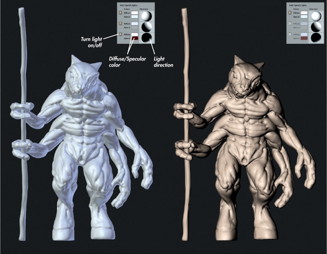
In Figure 6-13, I’ve tweaked Blender’s standard OpenGL lighting. To do this yourself, open User Preferences and, in the System tab, locate the Solid OpenGL Lights settings, as shown in Figure 6-13. These settings give you three independent “lights” that determine how meshes are shaded in Blender’s default solid shaded view. You can turn these lights on and off using the lightbulb icon, adjust their diffuse and specular colors with the color pickers, and change the direction from which they light the mesh using the spheres on the right.
To make the lighting more amenable to sculpting, I turned off the second and third light sources and set the first light source to point straight at the mesh, giving it a slight tan color. This resulted in the shading on the right in Figure 6-13, which is more directional and gives a better idea of the shape of your mesh while sculpting.
The Multires Modifier
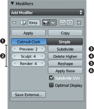
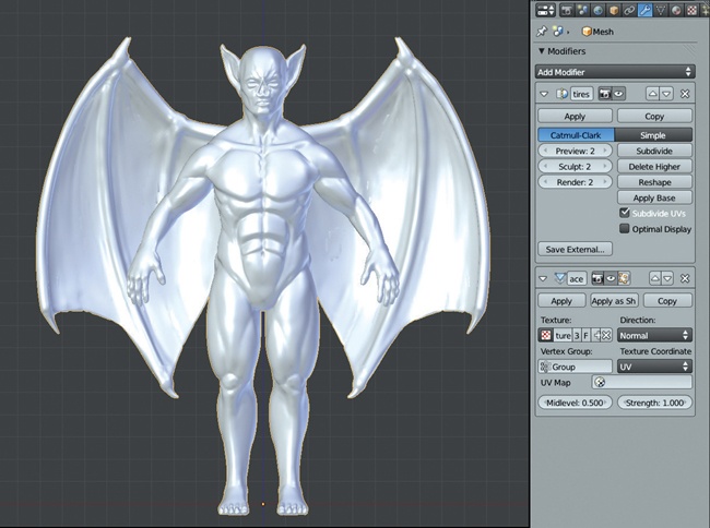
While you can sculpt on any mesh, we need to use the Multires modifier in order to take a sculpt to a high level of detail while maintaining a base mesh that is still simple to edit (see Figure 6-14). The Multires modifier is similar to the Subsurf modifier in that it subdivides your model using either Catmull-Clark or Simple subdivision 1. However, instead of being purely procedural, the Multires modifier will store further editing of your mesh in Sculpt mode, allowing you to first subdivide your mesh and then use the extra geometry this creates to sculpt in extra detail. This lets us subdivide a fairly basic model into millions of polygons and allows us to sculpt them into whatever shapes and with whatever details we want.
The three settings on the left of the Multires modifier panel (Preview, Sculpt, and Render 2) determine the level of subdivision shown in different modes. Preview sets the display level for Object mode, Sculpt the level for Sculpt mode, and Render the subdivision level used when rendering the mesh. The Subdivide operator 3 adds another level of subdivision each time you click it, while the Delete Higher operator 4 deletes any subdivision levels above the one you are currently working on.
If you happen to export your mesh to another program, or duplicate and edit it separately, you can use the Reshape operator 5 to reshape your Multires mesh to be the same as that of another selected object. In order to do this, though, both meshes must have identical vertex order and topology, and any deletion or adding of vertices will break this functionality. If you’re exporting to another program (like ZBrush or MeshLab), be sure to use the .obj format and ensure that the Keep Vertex Order option is checked when importing and exporting.
The Multires modifier does not affect the original shape of your mesh; however, you can use the Apply Base operator 6 to fit the lowest subdivision level (your original mesh) to the shape of the subdivided mesh. This is useful if you have done a lot of sculpting and want your base mesh to resemble more closely the shape of the sculpted mesh again.
Vertex Order
Blender (and any application that uses mesh objects) stores a mesh as a numbered list of vertices, along with the connections between them that make up the edges and faces. This is the object’s vertex order, and it must remain unchanged in order for the Reshape operator to function. Simple manipulations of these vertices—like moving, rotating, or scaling—will not affect their ordering, but adding or deleting vertices will. Additionally, saving to other formats when exporting or importing may reorder the vertices of a mesh.
Subdivision and Polycounts
When working with the Multires modifier, you can track the polycount of your scene using the Info Editor header (see Figure 6-15). Remember that each subdivision you apply multiplies the polycount of that object by 4, so subdividing a mesh five times increases your polycount by a factor of 1024! Depending on how much RAM you have, you can probably safely subdivide up to a million or more polygons, but the number of subdivision levels that this requires will really depend on the number of polygons in your base mesh.
The Info Editor header contains several useful numbers. These are, from left to right: the version of Blender you are using, the total vertex count (Ve:) of the active layers, the total polygon (face) count (Fa:) of the active layers, the number of objects (Ob:) selected and in total (selected-total), the active layer, memory usage, and the name of the active object.
Sculpting Concepts
With Blender set up nicely for sculpting, let’s get to it. In general, we’ll sculpt from coarse to fine, just like sculpture in the real world. By beginning with the broad structure of the final product we want to achieve and working toward the fine details, we reduce the number of steps we need to undo in order to correct errors.
This section will introduce you to some general concepts in the order I think about them when sculpting.
Volumes and proportion. When beginning to sculpt, first set out the rough shape of your subject; in other words, create a rough volume for each component of your overall figure. When sculpting a character, you should block out the volumes of the legs, arms, torso, head, hands, and feet. This is accomplished partly by creating a good base mesh. For example, we already created the basic shape of the Bat Creature character in Chapter 4; however, this can still be refined and improved while sculpting to give a better feel for the size and overall shape of the model.
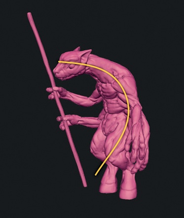
Gesture. Gesture describes the stance of a character and the flow of forms from one body part to another. This stage applies more to posed characters but is an important part of creating a good neutral pose, and even applies when sculpting inorganic forms. Key at this stage is that the forms of the body are connected by smooth, flowing curves. You should usually be able to draw a smooth curve through your character’s pose, as shown in Figure 6-16.
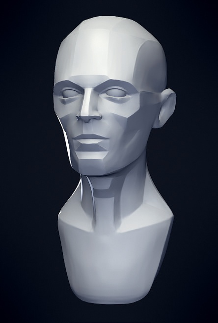
Planes. By planes, I mean breaking down and simplifying the form of the object into flat planes—areas of the object that form broadly flat surfaces rather than polygons. The direction and placement of the planes in your sculpture determine how the surfaces of your objects catch light, creating patterns that in turn play a large part in how we read and recognize shapes.
Even though you’ll ultimately smooth out these planes, they’ll still influence your finished object. For example, the planes in a human or humanoid character are largely defined by the object’s major anatomical landmarks, such as the bony parts of the skull, ribcage, collar bones, and pelvis. In Figure 6-17, the main large planes are defined by the shape of the skull; these planes include those along the side of the head, along the jawline and chin, and down the bridge of the nose. Smaller secondary planes form the shapes of the ears, lips, and nostrils. (You don’t actually need to define the planes of your model too rigorously, as they will be smoothed out later, but it is important to know and roughly mark in where they are.)
Coarse details and anatomy. Once you’ve finished creating the main volumes and planes of your sculpture, you’ll find that many of the anatomical details are actually already present, though there are still many anatomical features to be added to the final sculpt. Achieving anatomical realism in your sculpts takes practice and is a matter of gathering and studying anatomical references and then placing and refining those anatomical landmarks on your sculpt.
One way to begin filling in the details is to start with the major muscle groups and skeletal landmarks and then progress to smaller details like the musculature and small features like fingers, ears, eyes, and so on. See Planes to learn how I accomplished this for the Bat Creature.
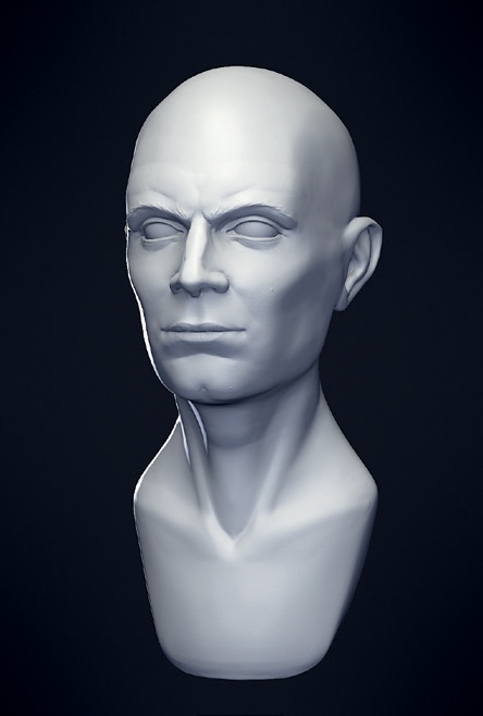
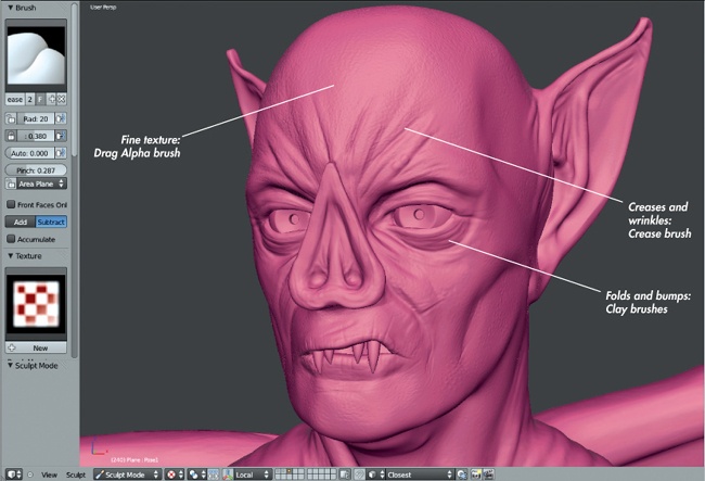
Fine details and surface texture. Finally, we progress to fine details, like wrinkles and pores in skin, or technical details in a hard-surface model (see Figure 6-18). This is a fun stage that can add a lot of character to a model. One thing to note at this stage is that, particularly with organic characters that aren’t heavily muscled, much of the anatomical detail you may have added will need to be toned down. You can either omit these details earlier in the sculpting process (but consider where they will be under the surface nonetheless) or smooth them away in areas where you need a subtler effect. Finally, you can start adding smaller details, like wrinkles, pores, scars, and so on. We can start smoothing and polishing out any artifacts we have created earlier while sculpting and then add more deliberate fine details.
These are the general stages that one goes through when sculpting. They take you from a rough overall shape to something with the key features you are trying to create and then allow you to re-create the finer details. Now let’s apply these stages to sculpting the Bat Creature and Spider Bot.
Sculpting the Bat Creature
For the Bat Creature, I began with a couple of simple base meshes that had topology to support most of the features I needed (though nothing for the face). Then I could begin developing the forms of the Bat Creature into something more interesting and add further details, such as some musculature and facial features.
To begin, I took the base mesh and added a Multires modifier and a few subdivisions. The initial aim was to add enough resolution to allow me to begin refining the volumes and defining basic planes and landmarks—but not so much that I would get sucked into adding details too early. When sculpting, try to make the most out of each level of subdivision before adding the next level.
Volumes
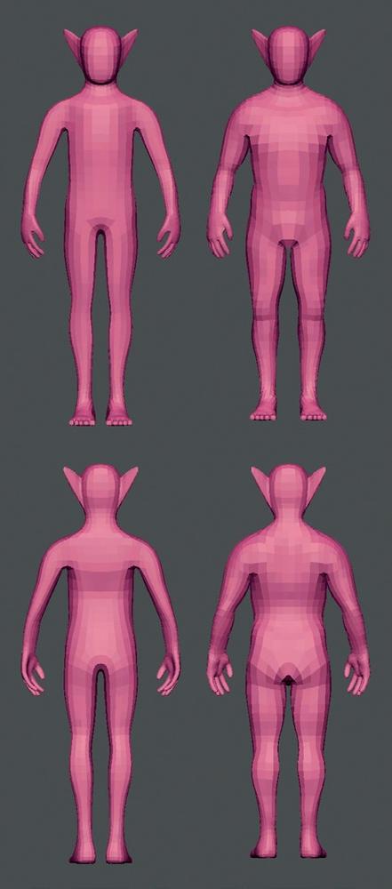
I began by adding volume to the legs and arms with the Inflate tool (see Figure 6-19). The Inflate tool is particularly handy at low subdivision levels for enlarging basic masses and giving them a nice rounded shape. The Clay tool is also handy for building up mass in a specific place. (It’s easy to make forms thinner again with the Smooth tool or with the Inflate tool in Subtractive mode.)
On the Bat’s torso, I began separating the bulk of the ribcage or chest from the pelvis and adding some muscle mass on the back for the shoulders. The Bat Creature is a character with wings coming out of its back, so large muscles on the back are expected.
Planes
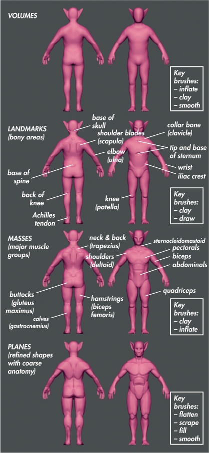
Next, I began sculpting the figure’s basic planes. Because I was adding more definition at this point, I first added a few more subdivision levels, bringing the overall polycount to a few hundred thousand polygons. The aim here was first to find the bony landmarks of the body, such as the top and bottom of the ribcage, the iliac crests of the pelvis, the knees and elbows, and the skull (see Figure 6-20, Landmarks).
As a first step, you can roughly mark these points with a light impression from the Clay brush. Next, you can place the secondary forms of the major muscle groups using these landmarks as a guide. To do this, simply add and subtract mass with the Clay brushes (Figure 6-20, Masses). Then you can begin flattening these masses out into the main planes of the body using the Flatten, Scrape, and Fill brushes (Figure 6-20, Planes). Using the Crease brush at this stage will allow you to create better divisions between planes in Subtractive mode (the default behavior for this brush); this brush can also be used in Additive mode to add sharp edges to planes that face outward.
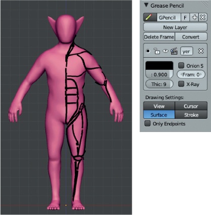
A good way to plan and keep track of the details you want to create is to sketch the muscle groups with Blender’s grease pencil, using the Surface drawing setting (see Figure 6-21). In Object mode and with your mesh selected, add a new grease pencil layer, set the draw mode to Surface, and then draw strokes on the surface of your mesh by holding down D and clicking to draw. Now you can sketch any anatomical landmarks on your sculpt before actually sculpting them in. For example, in Figure 6-21, I have sketched out the major muscle groups.
Coarse Anatomy
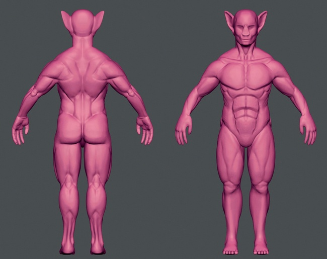
With our planes sketched out, we can move on to further defining the anatomy. References are particularly handy at this stage as we define further anatomical details using brushes like Clay, Clay Tubes, Crease, and Inflate to accentuate individual muscles and the bones of the body and the face (see Figure 6-22).
Sculpting Hard-to-Reach Areas Using Shape Keys
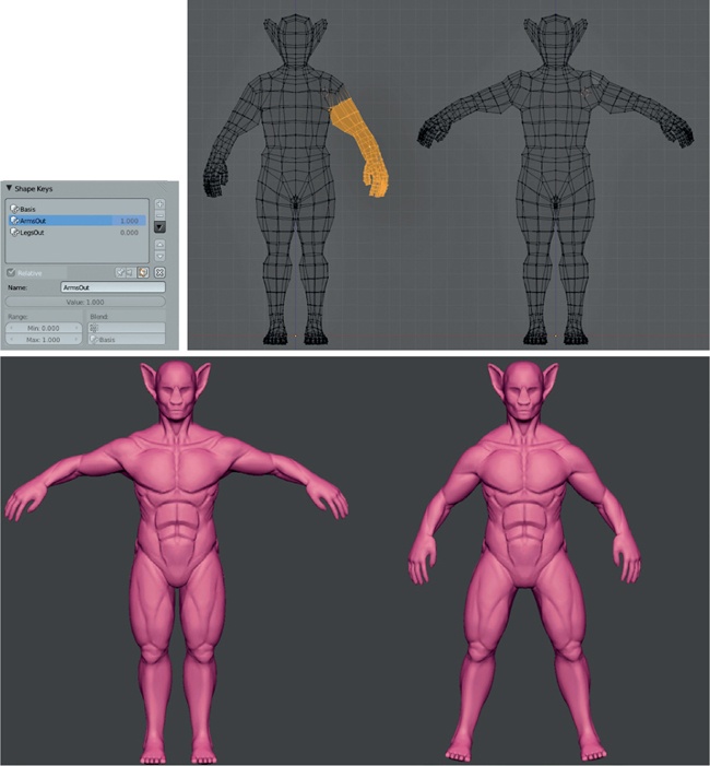
Some areas, like under the armpits or between the legs, can be awkward to reach with your sculpting brushes. To make the task easier, create a new shape key for your mesh in Edit mode that will let you reach the area you want to work on.
Shape keys allow you to store different positions for the vertices of your mesh, enabling you, for example, to have one position with the arms up, one with the arms down, or whatever position you wish. Shape keys are fully compatible with Sculpt mode, meaning you can blend them on or off to change your sculpt’s pose while sculpting. For example, for this sculpt, I created shape keys with the character’s arms and legs held further out to make it easier to reach the armpit and inner leg areas.
To create the shape keys, I first added a new shape key in Object mode to hold the new pose. (Click the + icon on the right of the Shape Keys panel twice to set the original shape of the mesh as the default “basis” shape; then click it again to create a new shape with the vertex positions stored relative to the basis shape.) Next, I selected the vertices of the arm in Edit mode and rotated them about the shoulder to bring the arm outward slightly. Then I adjusted the surrounding vertices to refine the new pose (see Figure 6-23). Returning to Sculpt or Object mode, I could then turn this shape key up or down (using the value sliders in the Shape Keys panel) to move the body into a position that would be easier to work on.
Hiding Parts of the Mesh
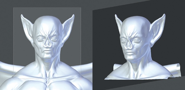
Another way to reach difficult areas in a sculpt is to hide part of the mesh using the shortcut ALT-B, which lets you drag out a box on the screen to restrict the visible part of your mesh to only what is inside the box (see Figure 6-24). By hiding parts of your mesh, you can concentrate on one small area of your model at a time and also see into more difficult or hidden areas.
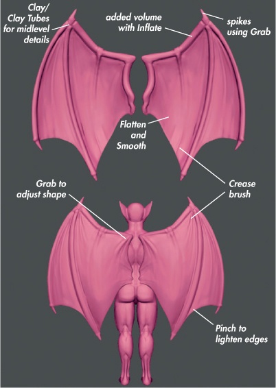
Sculpting the Wings
Next I moved on to sculpting the wings (see Figure 6-25). The wings required less work, as the basic shape was closer to the final look I wanted.
I began by using the Inflate brush to add some volume to the wing bones, and then I added some bony landmarks. Next, I refined the planes of the bones and gave them clear boundaries with the Inflate, Crease, Flatten, and Clay brushes. The Crease Lazy brush that we made earlier comes in handy for working on the outlines of the bones and adding ridges to the wing structure.
Basic Details
While I wasn’t planning to finalize the fine details covering the Bat’s body until retopology, I still needed to add the main features of the head: the eyes, nostrils, mouth, and details of the ears. Returning to the body, I began to add these details. The Crease brush is an excellent way to draw in the outlines of these details—such as the valley between the lips and the creases of the brows and around the nose—before using the Clay brushes to build up the basic forms and the Flatten and Polish brushes to refine them (see Figure 6-26). Later, these would be retopologized and resculpted, so I left them pretty rough for time being, just doing enough to indicate the general shape.
Sculpting Around the Eyes
Eyes can be tricky to sculpt because you need to follow the underlying shape of the eyeball while adding the details of the eyelids and such. To make things easier, first add a new sphere object as a placeholder for the eyeball (see Figure 6-26), then sculpt the eyelids around the sphere. A Mirror modifier can be used to create the other eye by using the body object as the mirror object in the modifier settings.
Time to Retopologize
At this point, I had reached the stage where adding further subdivisions would be slow and unwieldy with the current topology (the polycount of the body at this point is over 5 million faces). By retopologizing at this stage, you can create a denser and more suitable mesh that gives a higher initial density of polygons in important areas like the face and hands, with better topology to support the coarser details. This will allow you to resume sculpting again after retopologizing and add finer details to the mesh without having to keep increasing the poly-count to ridiculous levels.
Note
Jump to Chapter 7 if you wish to follow along in strict chronological order. From here on, I will be transferring existing details to a new retopologized mesh before moving on to add finer details.
Transferring Sculpted Detail to a New Mesh with a Displacement Map
Having retopologized the sculpt, I was left with transferring the details I had sculpted on the original mesh to the new one. There are several ways to approach this, each with its advantages and disadvantages. One way is to use the Shrink Wrap modifier: first adding a Multires modifier to your new mesh, then subdividing a few times, adding Shrink Wrap modifier, and setting the original mesh as the target. This can work reasonably well for simpler sculpts, but for more complex objects, it can create some artifacts and errors that will take time to straighten out. As such, for more complex sculpts, a better method is to use a displacement map.
About Displacement Maps
A displacement map is an image texture that defines how to displace the surface of a mesh according to the value of the texture: White areas cause the surface to be raised, and black areas are pushed in. By UV unwrapping the mesh and applying a displacement map to the new mesh, you can transfer the details of the old sculpt to the new mesh.
To create a displacement map, use Blender’s texture-baking tools to calculate the distances between the surfaces of the original sculpt and the newly retopologized mesh and to bake them into an image. Then, by using the Displace modifier (combined with the Multires modifier to subdivide the mesh), you can apply this displacement to make the new retopologized mesh exactly match the old one. (UV mapping is covered more thoroughly in Chapter 8 and texture baking in Chapter 10, so I will only touch on the basics here.)
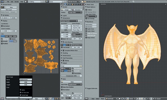
I created a simple UV unwrap for my retopologized mesh by tagging some seams (CTRL-E) to split it into easy-to-unwrap patches. Then I unwrapped it using the Unwrap operator (U▸Unwrap) and packed the UV islands into the UV grid. (You can do this automatically with the shortcut CTRL-P.)
Next, I assigned a new image to the object’s UV coordinates by selecting the object, entering Edit mode, and, in the UV Image editor, using Image▸New Image to create a blank, 4096×4096 image for baking displacement. (Be sure to check the 32-bit float option for best results when creating this image, as displacement maps with lower bit depths can cause nasty stepping artifacts.)
Finally, I baked the displacement from my original sculpt to the new retopologized mesh (see Figure 6-27) by following these steps:
Select the original sculpt.
Use SHIFT▸Select the retopologized mesh and apply a Subdivision Surface modifier to it with a render level of 3. This will subdivide the mesh before calculating the displacement so that later, when we use a Multires modifier to subdivide the mesh, the same displacement can be applied.
In the Render tab of the Properties editor, open the Bake panel.
Make sure that Selected to Active is enabled and Bake mode is set to Displacement.
Leave the Distance parameter set to the default of 0.
Click Bake to bake your displacement map.
Once it is baked, save your displacement map as an OpenEXR file from the UV Image editor by selecting Image▸Save as Image from the header menu (making sure to set the file type to EXR when saving).
Applying Displacement to the Sculpt
Once the displacement map image has been baked, you need to create a texture that uses this image and apply it as the input for a Displacement modifier applied to the new mesh.
Note
The procedure outlined below is somewhat inelegant because in order to edit a texture’s properties, Blender requires you to assign it to a material, world, or brush. To get around this, you can create a “dummy” material to assign the displacement texture to so that you can edit it and then assign it to the displacement modifier. (For more on how images, textures, and materials normally work, skip to Chapter 10, Chapter 11, and Chapter 12.)
To apply the displacement map to your new retopologized mesh, do the following:
Select your retopologized mesh and, in the Materials tab of the Properties Editor, create a new material for it by clicking the New button. We won’t be using this material to render our mesh later; it’s just there as somewhere to hold our texture for now. You can rename this material something like Displacement_Dummy. You may also want to create a fake user for this material by clicking the F icon next to its name so that when you assign a different material to the object (leaving the dummy material unassigned), the dummy material will not be discarded.
Switch to the Texture tab of the Properties editor and add a new texture to the material, again by clicking New.
Set the material type to Image or Movie and then, from the Image panel below, click Open and load the displacement map you just created. Name this something memorable as well.
Delete the Subdivision Surface modifier we added earlier and add a Multires modifier to your retopologized mesh instead. Then subdivide it a few times. Aim for roughly the same number of faces as your original mesh for now.
Add a Displacement modifier. From the Texture selector, choose your displacement material and leave direction set to Normal, but change the Coordinates setting to UV to use your object’s UV coordinates to apply the displacement texture. Because we kept the texture-baking settings mostly on their defaults, the default strength of 1 should be exactly what we need. This should now give your mesh exactly the same shape as the original sculpt.
Controlling Displacement with a Vertex Group
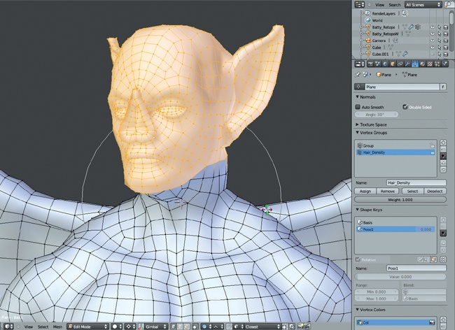
Some areas, like the inside of the mouth, may cause problems when the Displacement modifier is applied. Since the inside of the mouth is completely new topology, it won’t have any useful information in the displacement map, and it would be better to exclude these areas from the effects of the Displacement modifier. To fix these areas, you can assign a vertex group to the Displacement modifier to restrict displacement to only certain parts of the mesh, leaving problem areas untouched. Figure 6-28 shows the vertex group for the Displacement modifier in Weight Paint mode; the inside of the mouth and eyes and the tips of the claws on the wings are not included in the group.
To create a vertex group, take the following steps:
Enter Edit mode, and in the Object Data tab of the Properties Editor, and click the + icon in the Vertex Groups panel to create a new vertex group.
Select the vertices you wish to be included in the group (that is, the parts of the mesh you do want to apply the Displacement modifier to), and click Assign in the Vertex Groups panel to assign them to the group.
Switch back to Object mode, and set this vertex group as the vertex group to use to restrict the effect of the Displacement modifier (the Vertex Group option is in the modifier settings; see Figure 6-29). The modifiers you should now have applied are shown in Figure 6-29.
Apply the Displacement modifier by clicking Apply. Its effects will be stored by the Multires modifier, allowing you to return to Sculpt mode and continue sculpting and adding details.
Detailing
With the retopologized mesh ready to be sculpted, I began working it over with various brushes and building in the fine details (see Figure 6-30). The Clay and Standard brushes are generally the best for defining the important forms, but alpha textures can be used to add texture much more quickly.
Beginning with the face, I added some of the major wrinkles with the Clay and Draw brushes. Then, I moved on to using alpha textures. Using the Drag Alpha brush discussed earlier in the chapter, together with some skin texture alphas, I began building up the surface texture of the skin.
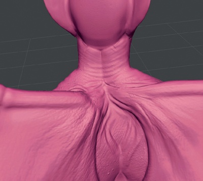
The rest of the body was covered in the same way: building up texture and fine details using a mix of alpha brushes and small Clay and Draw brushes. In the areas around the shoulders and wings, I added some creases that flow with the expansion and contraction of the wings, using a mix of alphas, Clay, and Crease brushes, as shown in Figure 6-31.
Procedural Details
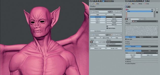
While it’s best to sculpt the important details of your model by hand, it can be handy to be able to add some generic roughness to the surface of your sculpt. We’ve used the Displacement modifier to transfer details using a baked displacement map, but we could also use other textures as the input for the Displacement modifier to generate some subtle variation in the surface. Blender has a variety of procedural textures (textures generated by various algorithms that do not require images as input) that are ideal for this purpose.
To add some surface detail to your sculpt with a procedural cloud texture and the Displacement modifier, do the following and see Figure 6-32:
Create a new texture block (we can use the dummy material created earlier to hold it) and set its type to Cloud.
Add a Displacement modifier to your sculpt (after the Multires modifier) in Object mode (Displacement will not be shown in Sculpt mode). Set your new procedural texture as the texture for the modifier.
Set the strength of the modifier to something very low. Then switch back to the Texture tab of the Properties editor and play with the settings of the Cloud texture, available from the Cloud panel that appears now that you have chosen the Cloud texture type. Try setting the scale of the cloud to something very small and play with the brightness, contrast, and noise basis to produce different effects.
As we did when we used a Displacement modifier to transfer details, you can use a vertex group to mask out areas that you don’t want to be affected.
When you have something you are happy with, apply the modifier to bake the results into the Multires modifier so that you can continue sculpting.
Breaking Symmetry
At this stage, if you keep symmetry enabled, your sculpt may begin to look a little too symmetrical. While the bodies and faces of most animals and characters are broadly symmetrical, fine details like pores, wrinkles, scars, and so on are not.
Once you reach the detailing stage, it is usually a good idea to turn symmetry off in the Tool Options. For more far-flung areas, like the ends of the arms and legs, you can leave symmetry on: Because these parts are farther from each other, the symmetry will be less apparent. However, obvious symmetry in the details running down the middle of your character will generally look strange, so turn symmetry off for these areas in particular.
Of course you can break symmetry much earlier; most characters and faces have some subtle asymmetry. This level of subtlety can add a lot of believability to your sculpts, so consider disabling symmetry earlier on.
Posing
To create a more interesting pose for my character, I jumped into Edit mode (TAB) and used proportional editing in Connected mode (ALT-O) together with rotating about the 3D cursor to move the limbs (see Figure 6-33). I created a new shape key for the pose and then began adjusting the body. For example, to move a leg, I selected all the vertices in the leg, placed the 3D cursor where the hip joint would be, and then rotated the leg about that point using proportional editing to create a smooth transition. This is a quick and dirty way to pose a character without resorting to rigging it, which is a complex task—and for a still render, more effort than it’s worth.
I adjusted the rest of the limbs and the head to pose the character in a more interesting way. Then I returned to Sculpt mode, where I used the Grab and Clay brushes at a low subdivision level to fix any errors with the pose and adjust the look of the musculature. I relaxed muscles that would be extended with the Smooth tool and decreased their volume a bit and conversely inflated and tightened up muscles that would be contracting in the new pose.
Expression
Facial expression is an important part of any character. I added a new shape key to hold the facial expression and used the Grab and Clay brushes to add a bit of a snarl to the Bat’s face (visible in Figure 6-32) by grabbing the sides of the nose and shifting them up slightly, pulling up the upper lip a bit, and narrowing the eyes. Adding some creases in those areas where the face is scrunched up and smoothing out stretched areas complements the details already added.
Sculpting the Spider Bot
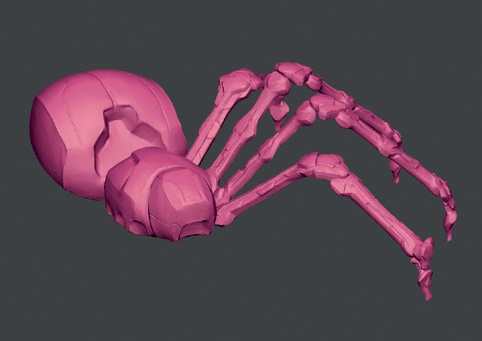
The Spider Bot was sculpted like the Bat Creature by first blocking out the major forms with the Clay and Grab brushes, then refining planes and adding details. However, in the case of the Spider, I had the added complexity of trying to create hard-surface forms. While you could model these sorts of forms directly (often an excellent approach), sculpting some aspects of hard-surface forms allowed me to be more experimental when creating our model.
While Blender can’t quite polish hard surfaces and sharp edges to perfection, you can accomplish a lot with the Flatten and Polish brushes along with the Pinch and Crease brushes. Then you can use retopology to create a finalized model with clean, smooth forms. By focusing on forms first and topology later, you reduce the hassle of trying to model forms you are not yet sure about and get your objects curving smoothly with clean topology later.
Body
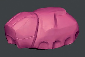
Beginning with the Spider Bot’s body, I used the Crease tool to roughly mark where I wanted the edges of my hard surfaces to fall. I next used the Clay brushes (the custom Clay Tubes brush is excellent for this purpose) to build up the volumes around these lines, and I used the Polish and Flatten brushes to refine them (see Figure 6-34).
To create even finer edges, combine the Crease brushes (the custom Crease Lazy brush we made is good for long, smooth curves) in Additive mode (hold CTRL) to make corners and edges sharper. Then, pinch them together to get a really sharp crease. By steering clear of the edges and using the Flatten brushes on the flat areas, you can achieve a fairly polished result. (Don’t go crazy; we’ll use retopology later to create a new mesh with smoother forms.)
Head
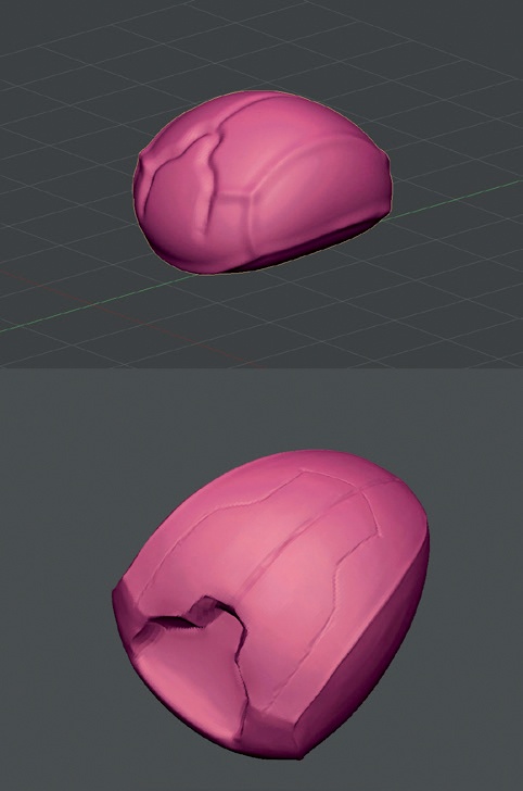
The head was sculpted the same way (see Figure 6-35), using the Polish brush to produce flatter shapes and the Crease brush to mark in edges and valleys. I also carved in some deep recesses where the legs and fangs will attach to the body.
Legs
Sculpting the legs proceeded in much the same manner. I started by polishing the overall shape of the pieces into something flatter and slightly more hardedged. Then I built up some more interesting shapes on top of that with the Clay and Crease brushes, first drawing out a design and then filling in the shapes. Next, I returned to polishing again to get more tightly defined, smoother shapes (see Figure 6-36).
Again though, there’s no need to chase after something perfectly smooth, as we will be fixing these surfaces with retopology in Chapter 7.
Note
The Polish and Flatten brushes can produce odd effects at sharp corners, creating awkward dents. To fix these, either undo or use the Inflate and Smooth brushes to knock out the dents and then re-crease and polish the surface.
To get an idea of the look of my sculpt at this point, I duplicated the leg parts (as linked duplicates, ALT-D) and moved and rotated them into place in Object mode (see Figure 6-37). This let me check on the final look of the model, though I didn’t bother mirroring the leg pieces over to the other side of the body at this stage.
Jungle Temple: Creating Incidental Details
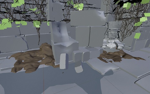
While the ruined temple scene didn’t use a lot of sculpting, certain incidental details were easier to sculpt, such as patches of mud and rough ground (see Figure 6-38). I created these areas mainly by using the Clay brushes without a Multires modifier, opting to simply subdivide the mesh a few times in Edit mode instead. I could have sculpted some damage into the stone walls using alphas, but I felt that the relative flatness of the walls contrasted nicely with the chaos of the surrounding foliage, so I left the masonry smooth.
Sculpting Natural-Looking Faces
While the Bat Creature has a face, it isn’t one that you’d call classically handsome. Here are some tips for sculpting more natural-looking faces.
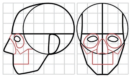
Focus on the proportions and the large volumes first before diving into the details. Lock down the overall volumes before adding wrinkles, pores, and scars so that you won’t have to redo them later when your sculpt doesn’t look right (see Figure 6-39).
Figure 6-39. Mapping out the proportions of the head. Overall, you can view the head as being constructed around the sphere of the cranium, with the face extending forward and downward from it. Here, the proportions of the head are laid out on a grid scaled to one eye-width per unit. Certain important features of the skull, including the cheekbones, eye sockets, and upper jaw, are marked in red.The head is roughly five eye-widths across and approximately seven down (see Figure 6-39). This proves a useful measurement. Keep this measurement in mind and use it to judge the relative distance and size of facial features.
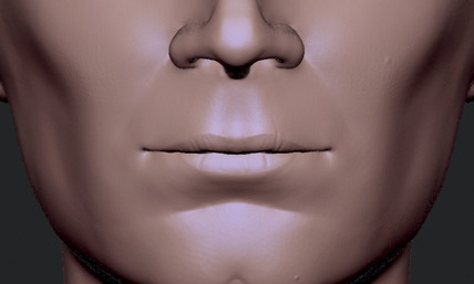
The mouth is difficult to sculpt. Depending on whether you have an “open” mouth (one with topology that follows round inside the mouth) or a “closed” one (one that is simply “drawn” onto the surface of the face), you will need to adopt different strategies. For open mouths, the Inflate and Smooth brushes are useful for adjusting the shape of the lips and the surrounding areas. For closed mouths, the Crease brush is perfect for drawing in the crease between the two lips, followed by filling out the surrounding areas with the Clay and Clay Tubes brushes. Remember that the upper lip generally has much more definition than the lower lip and has a rough M shape to it. The lower lip is more rounded and slightly tucked under the upper lip in most people (see Figure 6-40).
The anatomy of the face and the landmarks of the skull are important. Try modeling or sculpting a skull, sculpting the facial muscles, and then adding the skin over the top to see how they affect one another (see Figure 6-41).
Don’t add lots of wrinkles and creases unless you want your character to look seriously old. Even a few subtle wrinkles can add a lot of character to a face.
Few faces are perfectly symmetrical. While sculpting with symmetry turned on will take you a long way, turn it off in the later stages of your sculpt to add a bit of uniqueness to the two sides of the face.
In Review
In this chapter, we have looked at the variety of sculpting tools that Blender has to offer and how to customize them to make the most of their capabilities. Then, we moved on to sculpting the Bat Creature’s body and turning the simple base meshes I created both for it and for the Spider Bot project into more detailed, developed models that are now ready for retopology. Finally, we discussed some general principles for sculpting faces.
In the next chapter, we move on to retopologizing our sculpts, bringing the modeling stages of the projects to a close. In later chapters, we’ll use our high-poly sculpts again for baking maps and textures for our models before rendering them with displacement and normal maps to recapture the details we created in this chapter.
