CHAPTER 29
Preventing and Solving Anesthesia Machine Problems
Introduction
The anesthesia machine began quite humbly as a basic device to deliver anesthetic gases. It has evolved to a sophisticated, integrated computer-assisted physiologic monitoring system and anesthesia delivery system. Fundamentally, the anesthesia machine continues to serve principally to facilitate gas exchange in the anesthetized patient; however, a number of functions have been integrated to improve the machine’s safety profile. Some of the notable improvements have included agent-specific vaporizers, oxygen proportioning systems, oxygen analyzers, oxygen failure safety valves, breathing circuit pressure monitors, and the pin index safety system. Anesthesia machines continue to evolve in sophistication with focuses on increased safety checks and improved consistency of the machine checkout routine (largely by removing human participation). With a broad group of manufacturers, market competition has encouraged a new emphasis on improving the user experience for the anesthesia provider. Some of the new key features include larger workspaces, touch-screen monitors, and integration of a wide variety of calculators, algorithms, and software tools for the anesthesia provider, including built-in spirometry (see Fig. 29.1).
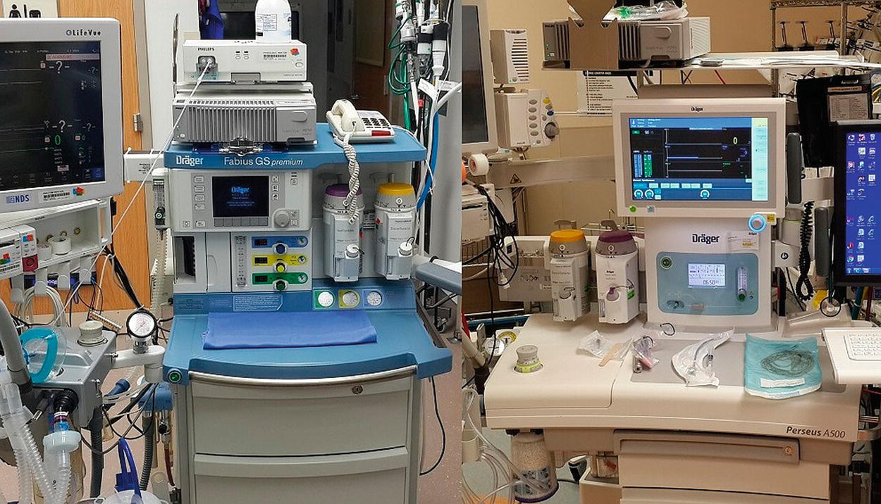
FIGURE 29.1. Comparison of anesthesia machines within the same company demonstrates how models evolve within just a 10-year period. Drager Fabius GS on the left has a bellows, hand dials, separate gas analyzer. Drager Perseus to the right has a touch screen, large workspace, integrated gas analyzer, completely automated self-checkout system, and the elimination of the bellows.
The anesthesia machine consists of various components managing gas delivery and elimination, including a ventilator, gas inflows from a variety of sources, anesthetic vaporizers, scavenging system, breathing circuit, and CO2 absorption system. All of these systems have appropriate check mechanisms and associated alarms or notifications to alert medical providers to potential problems. While there are a number of machines available on the market, they share similar fundamental components and functionalities. It is therefore critical to have a basic understanding of the principles of the workings of the machine. Such a core base of knowledge is absolutely necessary to safe practice and the maintenance and evaluation/troubleshooting of anesthesia machines. Despite the similarities between anesthesia machines, it is important to recognize that machines have distinct differences. Anesthesia technicians should be thoroughly familiar with the unique properties of machines in use at their institutions and must be ready to adapt with the rollout of new machines that are more sophisticated than their predecessors.
The American Society of Anesthesiologists (ASA) and the Food and Drug Administration (FDA) have collaborated to develop recommendations for checking out an anesthesia machine prior to administering an anesthetic (see Chapter 25, Anesthesia Machine Checkout). Each manufacturer provides maintenance schedules, troubleshooting instructions, and guidelines for checkout of its specific machines. Internal machine designs vary; hence the need for specific manufacturer recommendations. In addition to testing machine components, the checkout will test associated alerts and alarms. Anesthesia technicians should have detailed knowledge of the anesthesia machine checkout procedures as this can be the first indication that there is a problem with a machine. Anesthesia technicians will also be asked to troubleshoot machine problems between cases or even during a case. This chapter assists the anesthesia technician with the fundamentals of operation, maintenance, and troubleshooting of anesthesia machines.
Brief Overview of the Anesthesia Machine
Although anesthesia machines can include several functions, the main function will always be to provide a controlled supply of oxygen and other anesthetic gases to the patient during surgery. The details of gas supply to the machine have been discussed previously (see Chapter 24, the Anesthesia Machine); however, a short review is presented here to facilitate a troubleshooting discussion (see Fig. 29.2).
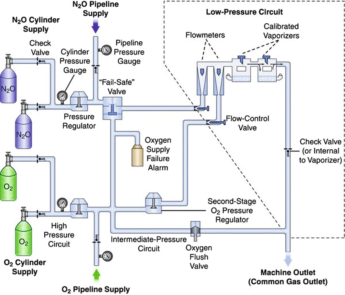
FIGURE 29.2. Diagram of a generic gas anesthesia machine.
The machine circuit can be broken down into high- and low-pressure circuits. The high-pressure circuit starts where the gas enters the machine and ends at the flow control valves. Gas enters the machine at a pressure near 50 psi from the pipeline. Gas can also be supplied from E cylinders, which supply a pressure of 2,200 psi for oxygen and 745 psi for nitrous oxide when tanks are full. This pressure is then further regulated to 45 psi downstream. Traveling toward the patient, the next device is the fail-safe valve, which is downstream from the nitrous oxide source and serves to decrease the supply of nitrous oxide if the oxygen pressure drops. Most Datex-Ohmeda machines also have an oxygen supply alarm that sounds when the pressure drops below a safe level. Both of these devices serve to decrease the potential for delivering a hypoxic mixture of gas. Gas then enters the flow control valves. The oxygen and nitrous oxide valves are coupled together to limit the percent of nitrous oxide that can be given as another means to reduce the risk of giving the patient a hypoxic mixture of gas.
The low-pressure system of the anesthesia machine begins downstream of the flow valves. Gas travels through the flowmeters into a common manifold and then into one of the calibrated vaporizers. Between the vaporizers and the common gas outlet, which connects to the patient circuit, there is a check valve that prevents gas from flowing backward through the vaporizers. Exhaled gas passes through the carbon dioxide (CO2)–absorbing canister and rejoins the fresh gas here as well. The combined gas fills the ventilator or the bag, depending on whether manual ventilation or the ventilator is selected. If excess gas is present at this juncture, it overflows to the scavenging system past the adjustable pressure limiting valve (APL, or “pop-off” valve), or through the ventilator relief valve. Gas then flows out through the inspiratory flow device past the oxygen analyzer to the patient through the inspiratory limb of the circuit. Expired gas is recycled as it flows back through the expiratory limb of the circuit, through the flow sensor, and then through the CO2-absorbing canister to ultimately rejoin the fresh gas from the common gas outlet prior to entering the ventilator or bag (see Fig. 29.3).
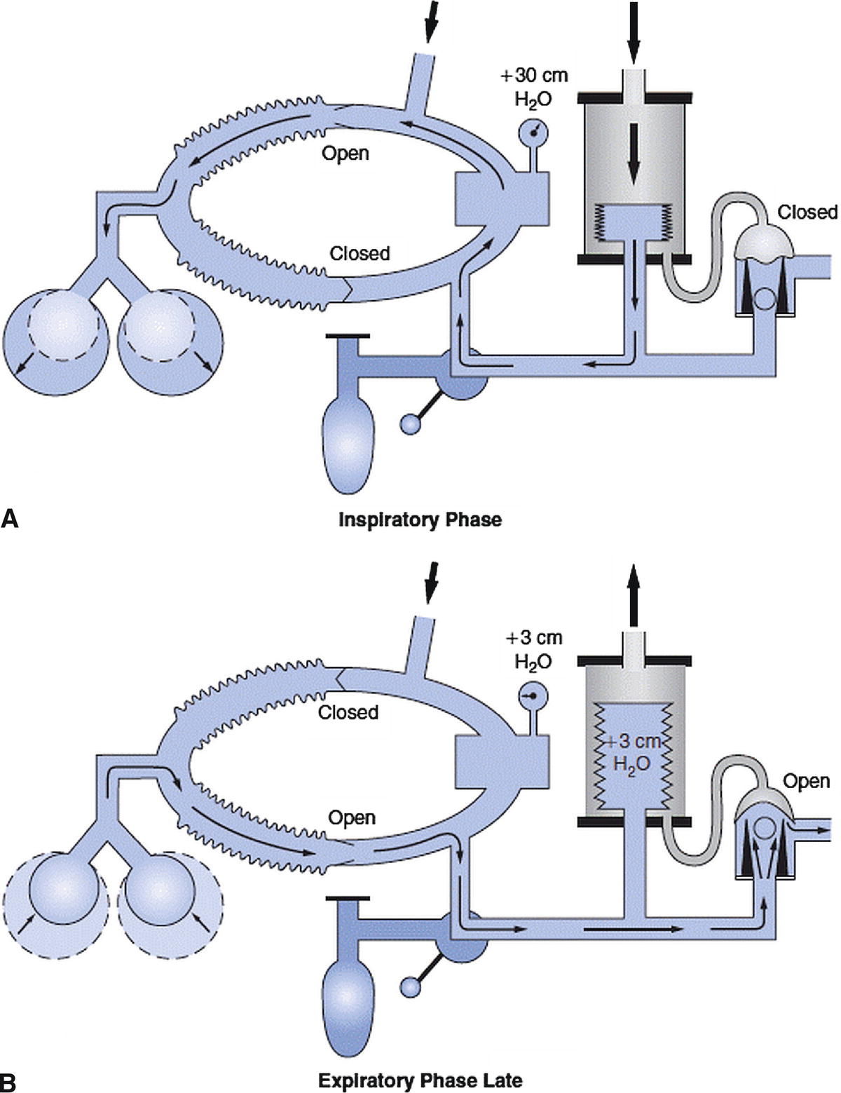
FIGURE 29.3. Picture of circle system with ventilator. A represents the inspiratory phase of ventilation and B represents the late expiratory phase of ventilation. (Reprinted from Andrews JJ. The Circle System. A Collection of 30 Color Illustrations. Washington, DC: Library of Congress; 1998, with permission.)
General and Daily Maintenance
Regular service should be performed by a machine representative according to the manufacturer’s recommendations. Daily maintenance by an anesthesia technician is crucial for proper function. Other chapters have described sterilization techniques (Chapter 47) and daily machine checkout (Chapter 25). These will not be covered in this chapter, but we will refer to the checkout process frequently because many of the problems that require troubleshooting can be prevented or later identified by the simple tests performed in a daily machine checkout.
At the end of the day, further routine maintenance should be completed. This includes removing the flow transducer to dry unwanted moisture, exchanging the CO2 absorber if it is exhausted, ensuring the gas flowmeters are off, and powering down the machine.
Troubleshooting Common Problems
The “human error” element may play a role in a number of anesthesia machine problems. Many of these errors may be due to either a misunderstanding of or a lack of attention to detail with machine checkouts, improper assembly of components, incorrect interpretation of alarms, or miscommunication between team members around machine management. Therefore, it is of utmost importance to take the necessary time to understand the natural history of how the problem arose in the first place to best facilitate a timely resolution.
Low Pressure
If low pressure in the anesthesia machine is detected, the following items should be examined:
- Check for low pressure leak.
- Check for a circuit disconnect starting with the patient and working back to the machine.
- Inspect bellows.
- Inspect CO2 canister.
- Check lids/coupling of vaporizers.
- Inspect the flow sensor.
- Check oxygen pressure from pipeline/cylinder.
- Check for incompetent ventilator relief valve.
The most common cause for a low-pressure alarm is a leak in the low-pressure circuit, and the most common cause of a leak is a disconnection or partial disconnection in the patient circuit. This is evaluated quickly, starting at the patient and moving back to the machine, evaluating the placement of the endotracheal tube (ETT), the ETT cuff pressure, the connection between the ETT and the circuit, the gas sample line port, and the connection of the inspiratory and expiratory tubing distal and proximal to the machine. If the leak is not resolved, continue to move upstream. Ensure the flow sensor is installed properly and tightly engaged. Check that the oxygen sensor is properly installed and all fittings are tight. Another common place for a leak is in the canister holding the CO2 absorber (see Fig. 29.4). Check to see that the latch is tight and that there are no granules in the way of the seal with the gasket. Also, look and listen for cracks in the canister and ensure that the condensation drain is closed. When the ventilator is turned off, if the pressure in the circuit returns to normal with hand ventilation, the leak can be isolated to the ventilator. The housing can be removed to look for cracks. This, along with poor seating of the plastic housing, can result in inappropriately low tidal volumes delivered to the patient because the driving gas is leaking into the room rather than compressing the bellows. Next, inspect the vaporizer lids to ensure they are on tight and inserted into the coupling system correctly. With the use of electronic flowmeters in newer machines, there are no fluted tubes that can crack, but this is another place a leak can occur and should be examined when mechanical flowmeters exist.
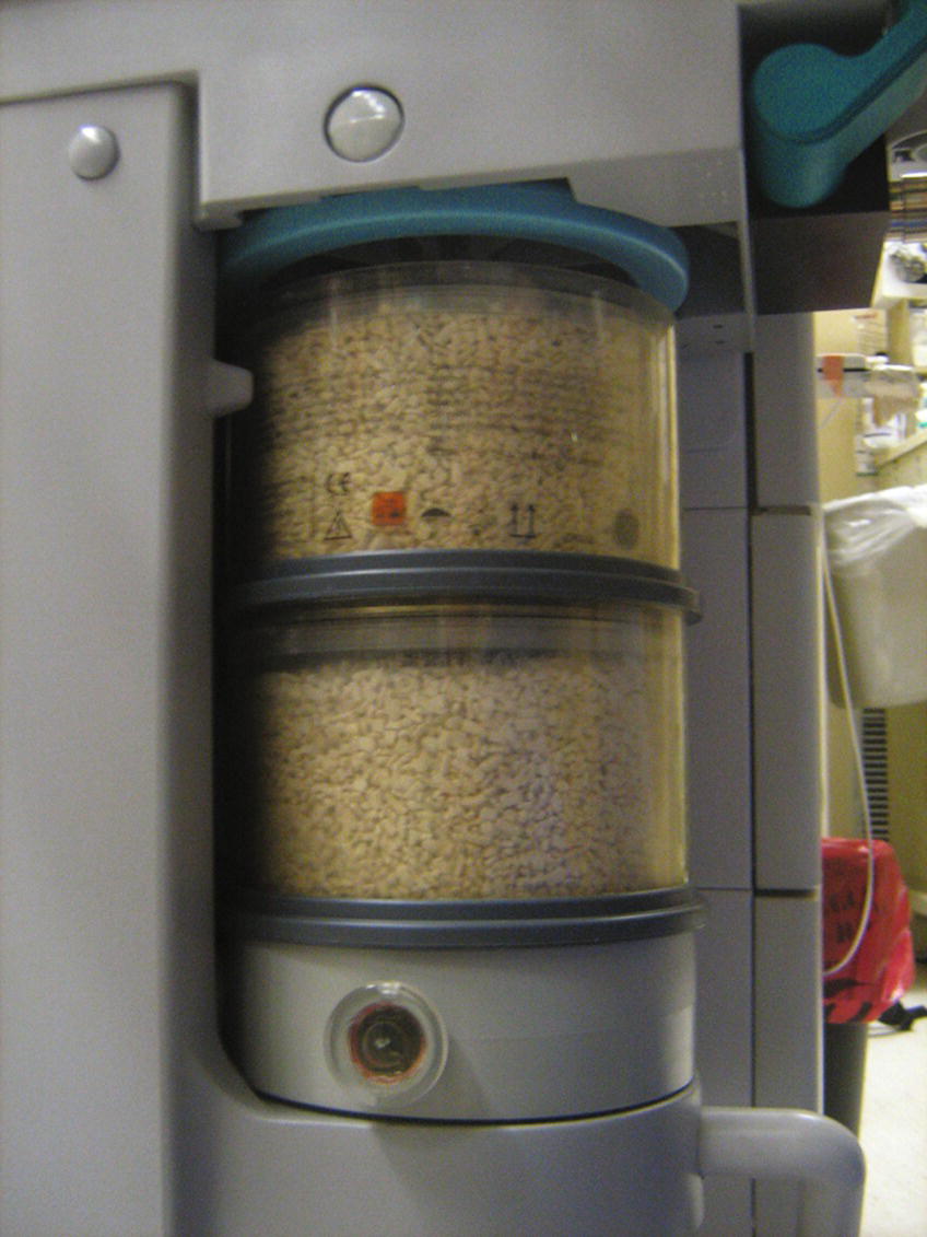
FIGURE 29.4. Carbon dioxide absorption canister in open/unlocked position (see space between plastic housing and blue plastic gasket); also condensation drain open at bottom.
It is uncommon for a low-pressure alarm to be due to problems in the high-pressure circuit, but they can occur. Pressure can be lost from inadvertent disconnects from the main supply, loss of the main supply pressure, or unrecognized depletion of a cylinder. Other less common causes may include a malfunctioning scavenging system or a scavenging vacuum set too high, such that the negative pressure from the scavenging system is able to lower the pressure in the circuit. Occasionally, high negative pressure in the scavenging system can also cause high pressure in the breathing circuit. In some machines, high negative pressure from the scavenging system can close the ventilator relief valve, blocking excess gas from exiting the circuit and leading to increased airway pressures. Lastly, an incompetent ventilator relief valve can lead to hypoventilation because gas is delivered to the scavenging system instead of to the patient when the bellows collapse.
Hypoxic Gas Mixture
- Turn on 100% oxygen and check for proper reading from the oxygen sensor.
- Recalibrate the O2 sensor.
- Replace O2 electrode if it does not appropriately recalibrate.
- Check for main pipeline crossover.
A common cause for a hypoxic gas mixture alarm is improper calibration of the oxygen sensor at the time of machine checkout. If the alarm sounds while a patient is connected to the circuit, the patient should be put on 100% oxygen (the patient may need to be ventilated with an alternative oxygen source during troubleshooting, e.g., bag-mask or replacement anesthesia machine). If the sensor does not read 100% after stabilizing for several minutes, the sensor should be recalibrated. If it will not recalibrate to the proper setting, the oxygen cell should be replaced. If there is a hypoxic reading, the high-pressure circuit should be evaluated. If a central pipeline crossover is suspected, the oxygen tank should be opened and the pipeline supply disconnected. If oxygen levels are restored by this change, it is critical to alert the appropriate hospital staff to avoid further serious adverse events.
Flowmeter Problems
- Check for a leak.
- Check for a stuck bobbin (see Fig. 29.5).
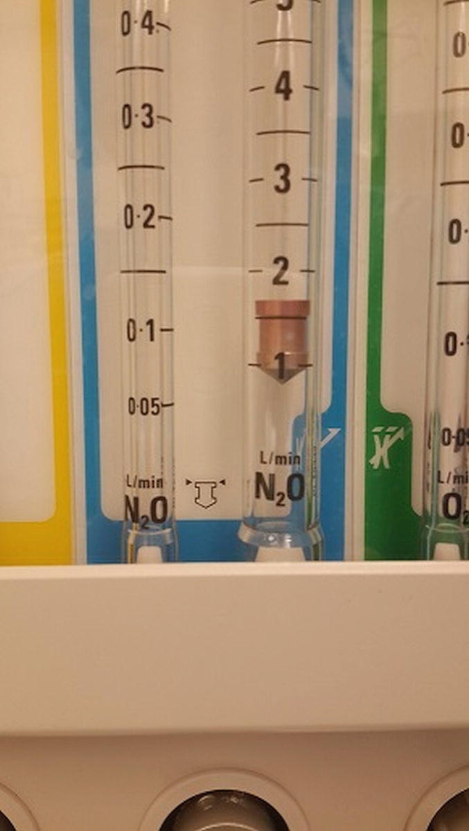
FIGURE 29.5. Flowmeter with fluted glass tube and floating bobbin. Bobbins should rise and fall smoothly with adjustments of gas flows and always be spinning slowly to demonstrate free movement of gas past them. Many current anesthesia machines measure gas flows electronically but may continue to display flows in a graphic format resembling this actual gas flow measurement device.
Flowmeter problems can often be detected during machine checkout. If the flowmeters are set to specific values and the oxygen or gas sensors are not reading the correct percentages of gas, either the sensors are malfunctioning or there is a problem with the circuit or flowmeters. Newer models of anesthesia machines are equipped with electronic flowmeters rather than the standard fluted glass tubes with a floating bobbin. Troubleshooting of electronic flowmeters should be done by the machine representative. The most common problem with fluted tube flowmeters is a float that is stuck from debris, leading to inaccurate readings. The quick fix is to gently flick the flow tube in an attempt to free the float from the debris. Ultimately, this should be brought to the attention of the machine representative for definitive cleaning and repair. The presence of a crack in the glass flow tube can cause a leak and thus a faulty reading. This can usually be detected during machine checkout when the low-pressure leak test is performed. Cracks that cause only a very small leak may be hard to detect. In some machines, a check valve, located between the common gas outlet and the flowmeters, prevents gas from flowing back through the vaporizer and into the flow tubes. In these machines, a positive-pressure leak test of the low-pressure circuit will not detect a leak in the flowmeters. A negative-pressure leak test should be performed on machines with a check valve in this location.
Ventilators
For a full description of anesthesia machine ventilators, see Chapter 28, Ventilators. A brief review is provided here in order to discuss how to troubleshoot common ventilator problems. The ventilator is typically pneumatically or mechanically driven. Mechanically driven ventilators use a piston-driven system to deliver a set volume or airway pressure to the circuit. Many current ventilators use an ascending pneumatically controlled bellow as part of a semiclosed circle system (Fig. 29.3). The pressure inside the clear plastic hood surrounding the bellows is regulated by a pneumatic circuit. During inspiration, gas enters the hood and the increase in pressure (1) closes the ventilator relief valve, blocking gas from going to the scavenging system, and (2) drives the bellows down, pushing anesthetic gas to the patient (older ventilators may have hanging bellows instead of standing bellows). During expiration, the pressure in the hood decreases, which allows fresh gas and scrubbed (i.e., CO2 removed) exhaled gas to fill up the bellows. The drop in pressure also opens the ventilator relief valve, and when there is back pressure inside the bellows (inside the breathing circuit), excess gas overflows into the scavenging system.
The ventilator system also incorporates airway volume and pressure monitors. Volume monitors often sense exhaled tidal volume and minute ventilation, but can also sense inspiratory volumes. Pressure monitors sense expiratory and inspiratory peak and plateau airway pressures. Default alarm settings are programmed into the machine to sound when certain volumes and pressures exceed or fail to meet specified limits. The volume sensor is often in the expiratory limb of the circuit and is susceptible to errors when too much moisture is in the system.
Ventilator Maintenance
Regular maintenance includes that performed by the manufacturer representative along with frequent visual inspections and functional testing, in addition to allowing the flow transducer and flow valves to dry at the end of the day.
Troubleshooting Common Ventilator Problems
Ventilator will not fill: The most common cause is a leak in the system. Perform the same steps as above to investigate a low-pressure alarm. In addition, check for an incompetent ventilator relief valve.
- Check for low-pressure leak.
- Check for a circuit disconnect starting with the patient and working back to the machine.
- Inspect bellows.
- Inspect CO2 canister.
- Check lids/coupling of vaporizers.
- Inspect the flow sensor.
- Inspect gas analyzer sampling rate.
- Check oxygen pressure from pipeline/cylinder.
- Check for an incompetent ventilator relief valve.
- Rule out ventilator problems by switching to manual ventilation mode.
- Rule out anesthesia machine problems by switching to an Ambu bag and/or an alternative form of anesthetic delivery (e.g., intravenous anesthesia). Perform a leak test.
Ventilator will not deliver a breath
- Look for inspiratory reverse flow/negative inspiratory flow alarm.
- Check for high airway pressures.
- Check for an incompetent expiratory valve.
Sometimes, the ventilator is unable to deliver a breath even though it is able to fill. A common cause of this problem may be with the flow transducer or flow valves. Alarms such as “inspiratory reverse flow” or “negative inspiratory flow” can be displayed on the screen. In each case, too much moisture in the circuit can affect the flow transducer’s capacity to measure flow. This can be resolved easily by exchanging the flow sensor for a dry one. High airway pressures can also limit the ventilator from delivering a proper breath, particularly when using pressure control ventilation. This will be addressed further below. If the expiratory flow valve is incompetent, the ventilator will be able to deliver a breath, but it will be much smaller than programmed, as there will be volume lost into the expiratory limb.
High airway pressures with mechanical ventilation:
- Check the breathing circuit from the machine to the patient for kinking or any type of obstruction
- Check the ETT for obstruction (kinking, secretions, mainstem intubation, etc.)
- Consider patient pathophysiology (bronchospasm, tension pneumothorax, stone chest, etc.)
- Check pop-off valve
- Check positive end expiratory pressure (PEEP) settings
- Check ventilator parameters.
There are many common causes for ventilator alarms to sound. Low airway pressure was addressed previously under the gas delivery section and is most commonly due to a disconnection or leak in the system. High-pressure alarms can sound because of a number of patient-related processes, including bronchospasm and pneumothorax. These should be addressed by the anesthesia provider and are beyond the scope of this chapter (but cannot be disregarded). There are several equipment malfunctions that can trigger a high-pressure alarm. The most common is due to an occlusion in the breathing circuit. Commonly, this is due to a kinked or obstructed ETT or a kinked hose on the inspiratory or expiratory limb. Once this has been addressed, ensure the pop-off valve and PEEP are set appropriately. If a volume-controlled mode of ventilation is in use, ensure the tidal volume is correct. Other possible contributors include problems with the scavenging system, which will be addressed below. Lastly, the parameters of the preset alarms should be evaluated and reset as necessary for the clinical situation.
Gas Analyzer
Historically, operating room (OR) gas analyzers were separate devices from the anesthesia machine. Newer models have gas analysis incorporated into the main machine. These monitor the concentrations of CO2, oxygen, and inhaled anesthetics (see Chapter 30, Gas Analyzers). A small gas sample line from the analyzer is connected to the end of the breathing circuit and samples are taken regularly from the inhaled and exhaled gas. The percent of gas is shown on the monitor. The continuous monitoring of CO2 levels is called capnography, and a tracing correlating to these levels is displayed on the monitor.
Maintenance of Gas Analyzers
The gas analyzer should be serviced by a machine representative. The water trap and sample tubing should be replaced regularly, especially if condensation can be seen.
Troubleshooting Common Problems with Gas Analyzers
No CO2 tracing:
- Check that the gas analyzer has been turned on and has completed its warm-up cycle.
- Check that the gas analyzer is not performing a temporary self-test.
- Check for sample line disconnect, obstruction, or discontinuity. Cracks in connectors are common.
- Anesthesia provider should confirm ETT placement.
- Check for a circuit disconnect.
Ensuring a proper CO2 tracing is part of the machine checkout, and most, if not all, problems should be identified early and easily rectified. If no tracing appears, there are two very common causes. First, ensure the machine is on and has had time to calibrate. Next, examine the sample line to look for kinks, disconnects, or fractures in the tubing (Fig. 29.6). Other problems that can be quickly fixed include checking to see if the moisture trap is inserted properly and not full of water. If the CO2 tracing “stops working” (i.e., is not registering a positive number) during the time of patient care, it is critical to first confirm that it is not a lack of patient ventilation before checking for a machine problem.
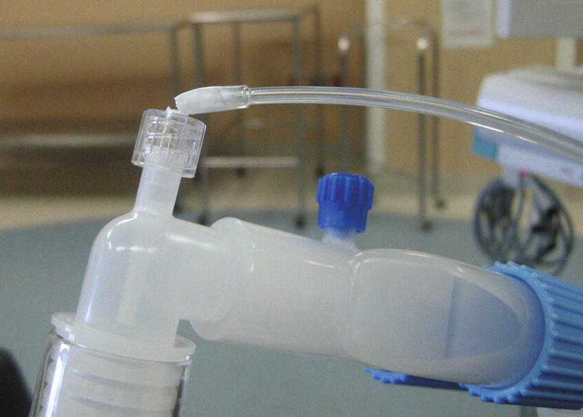
FIGURE 29.6. Gas sample line has been broken at the connection from surgeon leaning on line during case.
Inaccurate gas analyzer readings:
- Check water trap for condensation.
- Check sample line for disconnect, obstruction, or condensation.
- Check for recent aerosolized medication administration.
- Check vaporizers (properly installed and not empty).
A common cause for inaccurate readings from the gas analyzer is condensation in the sample line and/or an incomplete connection to the machine. Kinked, fractured, or poorly connected sample lines can also cause faulty readings (Fig. 29.6). If aerosolized medication is given through the ETT, the gas analyzer can often have trouble identifying the various gases. For example, aerosolized albuterol may give an end-tidal reading of halothane, despite the complete absence of halothane. Less commonly, end-tidal and inspiratory gas readings may not correlate with the vaporizer dial. If desflurane is the gas, ensure the electronic vaporizer is plugged in. Alarms should sound from a battery if it is unplugged, but if the battery is depleted, no alarm will sound. Another cause related to the vaporizer is spilling of volatile agent when the vaporizer is tipped. This can be rectified by flushing the system for 20 minutes at high flows with the vaporizer set at a low concentration.
Agent Concentration
Occasionally, the anesthesia technician will be called to manage unexpected agent concentrations. Inaccurate delivery of volatile anesthesia can have disastrous results. If there is more volatile anesthesia than expected being delivered, it can result in cardiac depression, low blood pressures, or difficulty waking the patient at the end of surgery. If the volatile concentration delivered is too light, it can result in a patient recalling events from the operation or moving at a crucial point, resulting in injury to themselves or providers.
Agent concentration is lower than expected:
- Check vaporizer dial setting and gas flows. Low flows can result in a lag of vaporizer dial settings as volatile anesthetic reaches the gas analyzer near the patient.
- Check reservoir level.
- Check the carrier gas.
- Check for leak in the circuit.
- Consider a recently exchanged component, including a new CO2 absorber, a new vaporizer attached to the machine, a new breathing circuit, or humidifier.
- Recent use of the oxygen flush button. This will inject fresh O2 into the system without concomitant volatile anesthetic.
Agent concentration is higher than expected:
- High vaporizer dial setting.
- Check for circuit component efflux. Inspiratory or expiratory valve leaks can result in retention of volatile anesthetic in the circuit without it being diverted to the scavenger system.
- Overfilled or tipped vaporizer.
CO2 Absorber
Exhaled gas from the patient travels back to the machine through the expiratory limb of the circuit and flows through the CO2 absorbent to be “scrubbed” of CO2. Most current anesthesia machines contain a clear cylinder into which prepackaged or loose CO2 absorbent can be placed. After flowing through the absorbent, the exhaled gas reenters the circle system and combines with the fresh gas to return to the bag or ventilator. The two absorbents used most commonly include soda lime and calcium hydroxide lime. The agent Baralyme was previously used; however, because of problems with adverse reactions with anesthetic agents, it has been removed from the market. Other problems with CO2 absorbents are due in part to oxygen that had been left flowing for a long period of time after the completion of a case, causing the absorbent to dry out; thus, it is very important that gas flow be turned off when a patient is not connected to the machine.
The absorption of CO2 from exhaled gas occurs through several chemical reactions, eventually forming sodium carbonate or potassium carbonate and water. A chemical indicator, ethyl violet, is added to the absorbent and changes from white to purple as the absorbent becomes exhausted, signaling that it is time to be replaced (see Fig. 29.7).
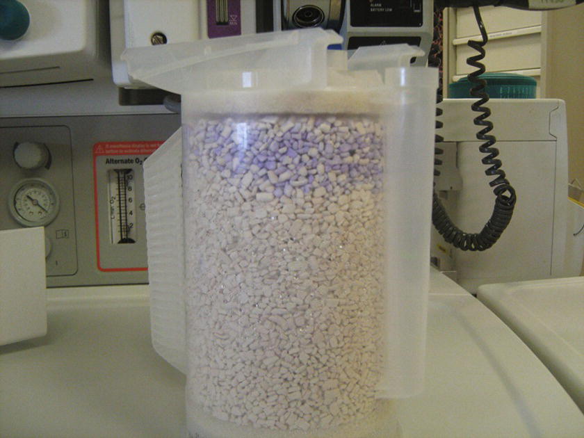
FIGURE 29.7. Partially exhausted granules; the exhausted granules will have purple tint in contrast to the white fresh granules.
Maintenance of CO2 Absorbers
The CO2 “scrubber” should be evaluated at least on a daily basis and should be part of the checkout between patients. When using low flows of fresh gas, a significant amount of absorber can become exhausted quickly. When replacing the canisters, ensure the plastic canister is closed (Fig. 29.4) and that there are no granules between the gasket and the plastic housing. If a drain is present in the bottom of the cylinder, water should be emptied daily.
Troubleshooting Common Problems with CO2
Elevated CO2 on capnography:
- Replace the CO2 absorber.
- Examine inspiratory and expiratory flow valves.
If an exhausted CO2 absorber is not recognized and replaced during the machine checkout, it will often be recognized intraoperatively, since the patient’s capnogram tracing will not fall to zero during inhalation. Although there are several other serious clinical scenarios that can cause this, commonly high inspired CO2 is due to exhausted absorber. Although not related specifically to the CO2 “scrubbing” system, another cause of elevated end-tidal CO2 is a faulty inspiratory or expiratory flow valve. The valves can become incompetent if they are damaged, dried out, cracked, or stuck in an open position from too much moisture (Fig. 29.8).
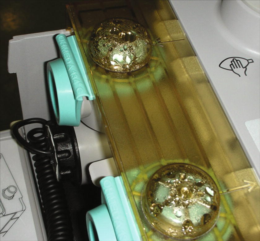
FIGURE 29.8. Moisture in inspiratory and expiratory valves causing incompetent valve on a Datex-Ohmeda Aestiva/5 machine. Moisture can accumulate in the ventilator when low gas flows are used in a patient’s breathing circuit for lengthy operations.
Moisture in the CO2 canister:
- Drain the moisture or replace the canister.
Because water is a by-product of the CO2 reaction with the absorbent, and the patient’s expired gas is humidified, condensation can accumulate below the CO2 canister. This can lead to higher airway pressures and sporadic PEEP pressures. A drain is often located at the bottom of the canister and can be opened to drain excess fluid that inhibits gas flow.
Scavenging System
There are three places exhaled gases can go when they leave the patient: (1) gas can escape into the room from a leak around a face mask or past a deflated ETT cuff; (2) gas can go back through the circuit into the bag, and if the APL valve is open, it will accumulate in the collecting assembly of the scavenging system; and (3) if the ventilator is engaged, the gas can fill the ventilator and then spill over to the collecting assembly through the ventilator relief valve. The scavenged gas then moves through the tubing into the scavenging interface or reservoir. Once in the reservoir, it is removed through a conduit to the disposal assembly, which is most often a central vacuum that pumps gas to the outside of the building. One of the safety features of the scavenging system exists in the interface. If the rate of flow is greater than the removal, a positive-pressure relief valve opens and gas spills out into the room, preventing an increase in the pressure in the patient circuit.
Scavenging System Maintenance
Maintenance is performed by a service representative at regular intervals. The dial controlling the suction in the disposal conduit should be checked daily and set appropriately.
Troubleshooting Common Problems with Scavenging Systems
Overwhelmed scavenging system:
- Turn down fresh gas flow if greater than 10 L/min.
- Check the vacuum control valve for proper adjustment (may need to increase the vacuum).
- Check that the gas disposal conduit is working.
An overwhelmed evacuation system most often presents with opening of the positive-pressure relief valve and the sound of escaping air into the room heard on expiration. The most common cause for an overwhelmed scavenging system is having high fresh gas flows with high minute ventilation. This can be checked by turning down the fresh gas flows and seeing if the evacuation system is capable of keeping the scavenging reservoir bag from becoming overdistended. If not resolved, the next step would be to ensure that the vacuum control valve is adjusted correctly. If the control valve is set too low, it is unable to keep up with the regular gas flows and the amount of vacuum should be increased (Fig. 29.9). If the reservoir is still distended after increasing the vacuum flow, check that the gas disposal conduit is working properly. Assess for any kinks in the line that could limit the elimination of scavenged gas (Fig. 29.10). If the vacuum is weak even after maximal adjustment of the valve, a problem exists in the central gas disposal system and should be addressed quickly to avoid gas contamination of multiple ORs.
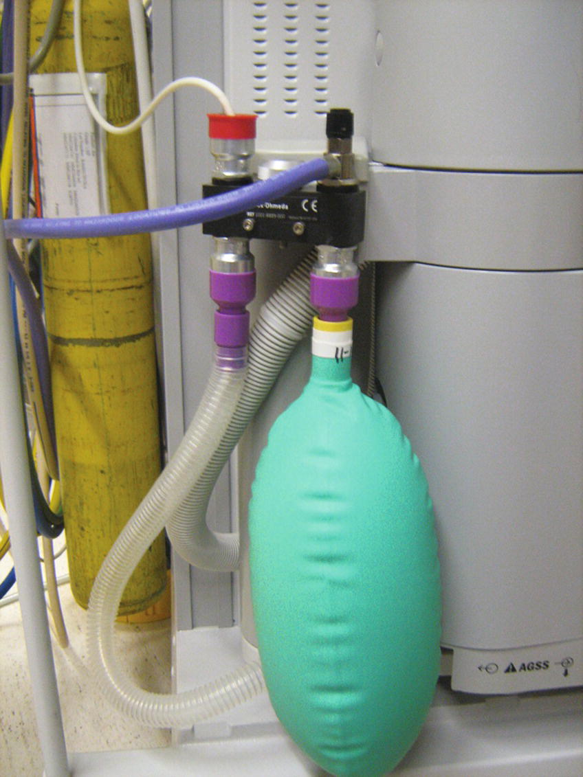
FIGURE 29.9. Distended scavenging reservoir due to inadequate level of vacuum suction or impaired pop-off valve.
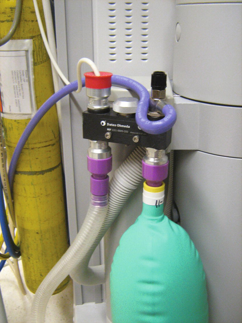
FIGURE 29.10. Kinked gas disposal tubing of scavenging system.
Increased circuit pressures:
- Check the transfer means for kinks.
- Check the vacuum control valve for proper adjustment.
- Check the positive-pressure release valve for proper functioning.
The most common cause for increased circuit pressures is typically not related to issues with the scavenging system. However, occasionally, the scavenging system circuit may become occluded in a location proximal to the pressure relief valve of the scavenger and cause high circuit pressures. Alternatively, high pressures in the scavenging system may result from a malfunctioning pressure relief valve, thus allowing the high pressure in the scavenging system reservoir bag to translate to increased circuit pressure. In both situations, increased airway pressures and barotrauma may result for the patient. The patient must be disconnected from the breathing circuit and ventilated by alternate means while the problem with the scavenging system is being corrected. If the problem cannot be immediately corrected, the patient must be ventilated manually for the remainder of the case, or a new anesthesia machine will need to be brought into the room.
Decreased circuit pressures:
- Check that the vacuum control valve is adjusted properly.
- Check the ventilator relief valve.
The most common cause for decreased circuit pressures is typically not due to problems with the scavenging system. But again, if the vacuum control valve is maladjusted, negative pressures may transfer to the main breathing circuit if the scavenger system has an incompetent check valve. This can be managed temporarily by adjusting the vacuum control valve so that the bag is not completely deflated with low circuit flows. An incompetent ventilator relief valve may also lead to lower pressures as gas is delivered to the scavenging system instead of the patient. As with the situation of an incompetent scavenger check valve resulting in high circuit pressures, when the incompetent valve results in low pressure, the anesthesia provider should consider changing the anesthetic to intravenous agents and then ventilating the patient with an intensive care unit (ICU) ventilator or Ambu bag until a new anesthesia machine can be brought into the room or the current machine fixed.
Summary
While equipment failure certainly does occur, many machine-related issues may be prevented through regular maintenance, a complete anesthesia machine checkout, and thorough understanding of the operation and design of anesthesia machines. The methodical completion of a thoughtfully tailored and specific checkout for your institution’s machines will help enormously in avoiding many of the commonly encountered machine issues and complications. When such events occur, you will also be better prepared to address the circumstance at hand. A regular maintenance program, in tandem with vigilance from the anesthesia providers, will help to identify many issues before they become system-threatening failures that lead to potential patient injury. The collaborative team approach between the anesthesia technician and the anesthesia provider is clearly demonstrated in this particular arena with significant overlap of responsibilities. Prompt cooperation and collaboration of all parties will help remedy the situation in a timely fashion and thereby minimize and/or avoid clinical complications.
Review Questions
1. Which of the following would correctly identify a leak in an oxygen flow tube?
A) Positive-pressure leak check
B) Oxygen analyzer
C) Negative-pressure leak test
D) All of the above
E) None of the above
Answer: C
Because most machines have a check valve between the patient circuit and the common gas inlet, a positive-pressure leak test will not identify a leak upstream. If a small leak was present, the oxygen analyzer would be unable to identify that 1 L of 100% oxygen instead of 5 L of oxygen was flowing through the circuit. Only a negative-pressure leak test will identify this.
2. The most common cause of improper delivery of oxygen to the patient is
A) Improper gas cylinder connected to the machine
B) Crack in oxygen flow tube
C) Crossing of gas supply from the wall
D) Disconnection of circuit from the patient
E) Incompetent inspiratory flow valve
Answer: D
Failure to properly deliver oxygen to the patient is most commonly caused by a disconnection in the patient circuit. Although improper gas cylinder connected to the machine, crack in oxygen flow tube, and crossing of gas supply from the wall can cause problems with delivery of oxygen, these are much less common causes. An incompetent inspiratory valve can lead to elevated baseline levels of carbon dioxide, but it should not cause poor oxygenation.
3. You are called into a room where the anesthesia staff complains that the airway pressure continues to rise in a relaxed patient with regular breath sounds. Which of the following problems with the machine could be causing this?
A) A kink in the scavenging transfer means
B) A faulty positive-pressure release valve in the scavenging system
C) An incompetent pressure relief valve in the ventilator
D) A and B
E) All of the above
Answer: D
If the scavenging transfer means is kinked, excess gas cannot be vented from the circle system to the scavenging system and barotraumas can occur from elevated airway pressures. This can also occur if flows are high in the system and the positive-pressure release valve does not function properly to vent the excess gas. An incompetent pressure relief valve in the ventilator will allow gas that is compressed by the ventilator to escape into the scavenging systems and would cause lower airway pressures and a leak in the circuit.
4. You are called into a room because of problems with the end-tidal carbon dioxide tracing not going back to a baseline of “0.” Which of the following could cause this?
A) Incompetent expiratory valve
B) Incompetent inspiratory valve
C) Exhausted soda lime granules
D) A and C
E) All of the above
Answer: E
The most common cause for elevated end-tidal carbon dioxide levels is exhausted absorbent, but improperly functioning inspiratory and expiratory valves can also cause this. Expired gas escapes down the inspiratory limb, and the patient is ventilated with this gas again. Inspired gas can also push a small amount of expired air back down the expiratory limb if the valve is incompetent. If this were to occur, the tracing would never reach “0” because small amounts of expired air would pass by the sampling port during inspiration.
5. The following steps should all be performed if a problem with the central gas supply is suspected in a room, EXCEPT
A) Open the oxygen cylinder on the back of the machine.
B) Alert the OR front desk.
C) Disconnect the wall supply from the machine.
D) Ventilate the patient with a separate circuit.
E) All should be performed.
Answer: D
If a central pipeline crossover is suspected, the oxygen tank should be opened and the pipeline supply disconnected. If the pipeline supply is not disconnected, gas from the tank won’t be used. If oxygen levels are restored by this change, it is critical to alert the appropriate hospital staff to avoid further serious adverse events. There is no need to change to a separate circuit once a proper oxygen source is connected to the machine.
6. The safety and reliability of oxygen and anesthetic gas delivery are principal concerns and of critical importance to safe medical practice. Which machine improvement is not a required safety component of the anesthesia machine?
A) Agent-specific vaporizers.
B) Electronic checkout.
C) Oxygen analyzers.
D) Oxygen failure safety valves.
E) All of the above are essential for safe anesthesia machine operation.
Answer: B
There are many key safety developments that have been integrated into the modern anesthetic machine and importantly include the components noted above in addition to circuit pressure monitors, pin indexing systems. Neither human nor electronic checkout is a perfect safety solution. Most current machines in service function rely on human checkout, and all providers and technicians should know how to checkout a machine manually and to troubleshoot machine problems.
7. Anesthesia machines have progressed in sophistication and complexity and routinely include a number of important components to manage gas delivery. Which of these is no longer used in gas delivery in all anesthesia machines?
A) APL (adjustable pressure limiting) valve
B) Bobbin flowmeters
C) Ventilators
D) Scavenging systems
E) Chemical CO2 absorption
Answer: B
While there are a number of anesthetic machines available and in use today worldwide, they principally share many similar fundamental components and functionalities, including anesthetic vaporizers, ventilators, scavenging systems, and CO2 absorption. Manual bobbin gas flowmeters for air, oxygen, and nitrous oxide, however, have been replaced by electronic flowmeters in most anesthesia machines currently being manufactured and sold. It is critical that one has a solid basic understanding of the principals of the workings of the anesthetic machine and its fundamental components.
SUGGESTED READINGS
Dorsch JA, Dorsch SE. Understanding Anesthesia Equipment. 5th ed. Philadelphia, PA: Lippincott Williams & Wilkins; 2007.
GE Health Care Aestiva/5. Anesthesia Delivery System Owner’s Handbook. Madison WI: Datex-Ohmeda, Inc.; 2003.
Miller DR, Eriksson LI, Fleisher LA, et al. Miller’s Anesthesia. 8th ed. Philadelphia, PA: Churchill Livingstone; 2014: Chapter 25.
Morgan G, Mikhail M, Murray M. Clinical Anesthesiology. 5th ed. New York, NY: McGraw-Hill; 2013:Chapter 1–4.
Riutort KT, Eisenkraft JB. The anesthesia workstation and delivery systems for inhaled anesthetics. In: Barash PG, Cullen BF, Stoelting RK, et al. Clinical Anesthesia. 8th ed. Philadelphia, PA: Lippincott Williams & Wilkins; 2017:644-708.