CHAPTER 24
The Anesthesia Machine
Introduction
The anesthesia machine has been developed over time from a basic gas delivery apparatus to an integrated system of components used to provide a safe anesthetic. It is the most important piece of equipment in the operating room. As an anesthesia technician, the more you know about the anesthesia machine, the more valuable an asset you will be to your department and your institution. This knowledge is critical given the increased complexity of the newest generation of anesthesia machines. If the machine fails, the operating room may be delayed or out of service or, worse, a patient could be harmed.
In this chapter, we will look at the components that make up today’s anesthesia delivery system. We will trace it from the gas supplies through the flowmeters, the vaporizers, the ventilator, and the breathing circuit to the patient and out through the waste gas scavenging system (Fig. 24.1).
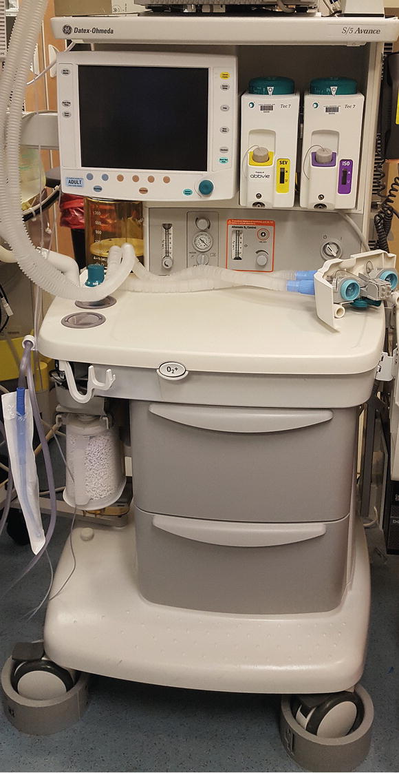
FIGURE 24.1. The modern anaesthesia machine is a complex assembly of integrated systems. The machine includes various gases and associated flowmeters, vaporizers, monitors, the ventilator, the breathing system, and the scavenging system. (Courtesy of GE Healthcare)
As an anesthesia technician, you need to know where you can get information about the machines your institution uses. Each manufacturer has specific technical manuals for each type of machine. Although frequently online, it is beneficial to have at least one hardbound edition available for quick reference. This can be important if the online manual cannot be reached due to power failure or network outage. In-depth resources include Dorsch and Dorsch’s Understanding Anesthesia Equipment and Ehrenwerth, Eisenkraft, and Berry’s Anesthesia Equipment: Principles and Applications. The University of Florida’s “Virtual Anesthesia Machine” is a good online resource for how machines work and for simulation and troubleshooting (http://vam.anest.ufl.edu).
Pipeline and Cylinder Gas Supply
Oxygen (O2), air, and nitrous oxide (N2O) are provided from two sources: central pipeline supplies and gas cylinders mounted on the machines. Safety systems are designed into every step of gas passage through the machine to prevent the delivery of a hypoxic mixture of gas to the patient. Beginning with the gas supply, specialized connections bring the gas from each pipeline supply to the anesthesia machine. The first of these is the Diameter Index Safety System (DISS), in which color-coded gas hoses connect to the wall outlet of each gas with different diameter threaded connectors. The connector of one gas cannot be connected to a different gas outlet, as the diameters would be different. These connections are also used for the hose-to-machine connection. The pressurized gas hoses often have quick-release connections that are noninterchangeable. These allow for the quick hookup or release of the machine gas hoses, which facilitates moving the machine and performing a machine checkout. The checkout of anesthesia machines is done prior to each anesthetic and verifies the integrity of the machine. Chapter 25, Anesthesia Machine Checkout, discusses the checkout process.
The compressed gas tanks attach to the machine by specialized yokes. The Pin Index Safety System (PISS) prevents the placement of tanks onto the wrong yoke. Two pins protruding from the yoke assembly correspond to two holes on the tank’s valve stem. Each gas has a specific standardized pattern. Therefore, each gas cylinder can only be attached to that gas tank’s yoke (i.e., O2 tank to the O2 yoke). An incorrect gas tank will not engage and seal to the valve openings of another gas’s yoke.
Gas tanks, like the pressure hoses, are color coded. The US color-coding standard differs from some colors used internationally (Fig. 24.2).

FIGURE 24.2. Each anesthesia machine has attached gas tanks as backup for the gas pipelines. The oxygen tanks are green, air tanks are yellow, and nitrous oxide tanks are blue.
- O2 = green
- Air = yellow
- N2O = blue
As gas enters the machine, there is a back check valve that keeps gas flowing only one way into the machine. If the machine has two O2 tanks and both valves are open, the back check valves prevent the equalization of pressure between the tanks (gas flowing from a full tank into an empty tank). The valves also prevent gas leakage out of the machine if the tanks or pipeline supply hoses are disconnected from the machine.
Oxygen E cylinder tanks are full at 1,900 psi (pounds per square inch) with 660 L of O2. You can quickly estimate the volume of O2 remaining in the tank by multiplying the current pressure in psi by 0.3 (e.g., 1,000 psi × 0.3 = 300 L). The volume of oxygen in the backup tank can be used to calculate how long oxygen can be provided to a patient if the wall source of oxygen is not functional. At an oxygen gas flow rate 10 L/min, 300 L would last about 30 minutes. It is important to note that some anesthesia machines use oxygen to drive the ventilator and may consume more oxygen than indicated by the oxygen flowmeter setting if the ventilator is in use.
After the gas enters from the tank, a pressure regulator reduces the pressure to approximately 45 psi. The gas pipeline pressure is usually 50-55 psi, but it can drop lower. This higher pressure from the pipeline allows the O2 to flow preferentially from the pipeline and preserve the O2 in the tank if the O2 tanks are left open. Gas may leak from the yoke if the tank is not properly mounted or when the tank is left open when the pipeline gas is delivered at a lower pressure than the tank. Leaks can also occur if more than one washer is improperly placed between the machine and the tank.
Oxygen Supply Failure Safety Devices
Within the anesthesia machine’s internal oxygen pathway is an oxygen supply failure alarm. This audible alarm is triggered if the internal oxygen pressure drops below a set value, usually 30 psi. A low pressure indicates a potential problem with the oxygen pipeline. Oxygen supply failure safety devices are also present within the machine before the gases pass into the flowmeters. These devices are designed to prevent hypoxic mixtures of gases from being delivered to patients in case of an oxygen supply failure. Although they reduce the chance of a hypoxic mixture, they do not eliminate it. These safety devices are triggered if the oxygen pressure drops below 20 psi.
There are two types of oxygen supply failure devices that react to a decrease in oxygen pressure: one shuts off the other gases and the other proportionally reduces gas flow. GE (Datex-Ohmeda) machines have a pressure sensor shutoff (fail-safe) device that will shut off the other gases. At pressures greater than 20 psi, the flow of these gases continues according to their specific flowmeter settings. In contrast, Dräger machines use a proportioning device, known as the Sensitive Oxygen Ratio Controller (S-ORC); as the oxygen pressure decreases, the S-ORC decreases the nitrous oxide flow proportionally until the pressure of both gases reaches zero.
Flowmeters
The flowmeters on the anesthesia machine display the flow of the specified gas in liters per minute. Flowmeters can be either electronic or mechanical. The mechanical flowmeters typically use graduated cylindrical glass tubes with a bobbin that corresponds to the flow (Fig. 24.3). The volume of flow is read by reading the height of the bobbin with respect to the numbers on the glass tube. The flow is read from the center of a ball-shaped float but from the top of all other bobbin designs. The oxygen flowmeter is always downstream from the air and nitrous oxide flowmeters. In the United States, this corresponds to the oxygen flowmeter positioned to the right of the other two flowmeters on the anesthesia machine. Newer anesthesia machines may display the gas flow electronically on a liquid crystal display (LCD) screen (Fig. 24.4) or with a graphical user interface.

FIGURE 24.3. Mechanical flowmeters display the flow of each gas with a bobbin corresponding to the dialed flow.
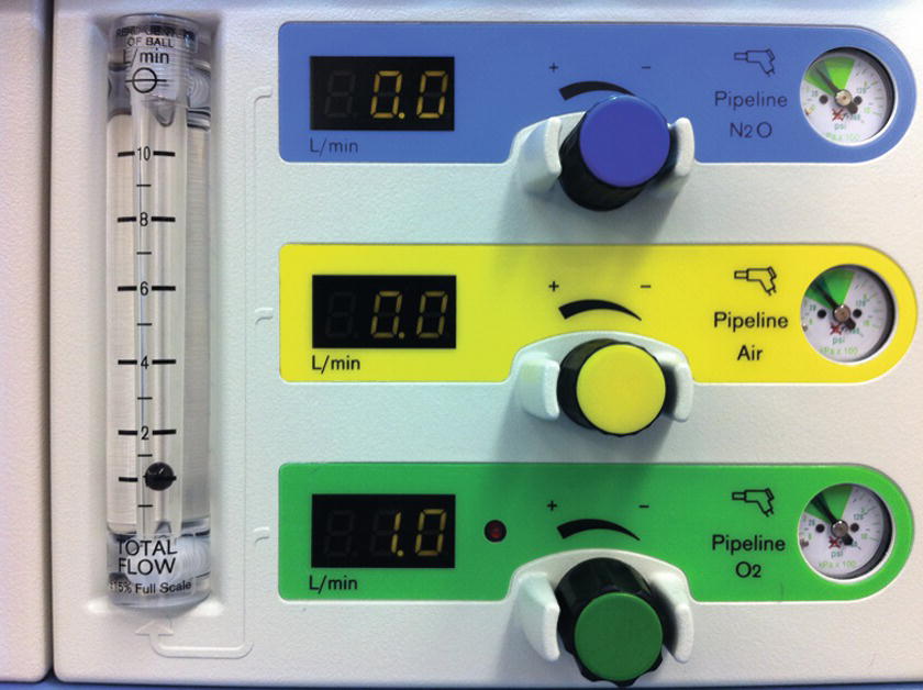
FIGURE 24.4. An LCD flowmeter display on machine with a separate screen for each gas. In this machine, there is also a mechanical flowmeter to the left, which displays total gas flow.
A mechanical or electronic linkage exists between the oxygen and nitrous oxygen flowmeter control valves. The linkage functions as a safety mechanism to prevent the delivery of an oxygen concentration less than 25% when using nitrous oxide. If a mechanical linkage is present, it connects these valves with a chain that does not allow the flow of nitrous oxide, unless the proportional flow of oxygen from the flowmeters results in at least 25% oxygen in the gas mixture. An electronic linkage uses a computer to determine the maximum safe nitrous oxide flow based upon the oxygen flow.
There is typically an auxiliary oxygen connection and flowmeter located on the anesthesia machine. This oxygen outlet usually has a barbed fitting that allows for the direct connection of nasal cannula or oxygen mask tubing. The flowmeter associated with this auxiliary oxygen connection is usually limited to 10 L/min.
Vaporizers
The purpose of a vaporizer is to convert the volatile anesthetic medication from a liquid to a set concentration of gas for delivery to the patient. Please see Chapter 26, Vaporizers, for more information on vaporizers. Within the anesthesia machine, the vaporizers are located between the flowmeters and the common gas outlet. The vaporizer has a number of components that are important to understand to ensure proper maintenance and service. Each vaporizer is designed to hold only one specific volatile anesthetic medication and is clearly labeled. Because the vapor pressure of each volatile anesthetic is different, placing the wrong medication in the vaporizer could result in the inappropriate delivery of medication. The filler port on the vaporizer is usually designed only to connect with the bottle of the correct volatile anesthetic medication, to minimize the likelihood of filling the vaporizer with the wrong drug. The output from the vaporizer is determined by turning the concentration dial on the vaporizer. The concentration of volatile anesthetic that is delivered to the patient is given in units of volume percentage and increases when the dial is turned in the counterclockwise direction. Vaporizers have a temperature compensation mechanism to ensure that the concentration dial reflects the output of the vaporizer despite changes in ambient temperature.
If there is more than one vaporizer present on the anesthesia machine, there is a mechanical link called an Interlink that prevents more than one vaporizer from being open at a time. This prevents the patient from receiving a simultaneous administration of two volatile anesthetics from the anesthesia machine.
Carbon Dioxide Absorber
The carbon dioxide (CO2) absorber is a critical part of the anesthesia machine that reduces the amount of exhaled CO2 that is inhaled by the patient. The CO2 absorber is a canister that contains granules of carbon dioxide absorbent (Fig. 24.5). During cellular metabolism, the patient generates CO2 that is exhaled into the circuit. The CO2 absorber removes exhaled CO2 before the circle system returns residual gas, containing anesthetic agent and O2, to the patient. The CO2 absorbent allows for the conservation of heat, moisture, and volatile anesthetic by allowing the patient to rebreathe the gas that he or she exhales. Without removal of CO2, the patient would inhale CO2 and the arterial partial pressure of CO2 (PaCO2) would increase as the CO2 accumulates. This could lead to the development of severe acidosis and eventually derangements in cardiovascular function.

FIGURE 24.5. The CO2 absorbent canister is an important piece of the circle breathing system and functions to remove the patient’s exhaled carbon dioxide from the anesthesia circuit.
There are various types of CO2 absorbents that are commercially available and are also discussed in Chapter 27, The Breathing Circuit. These absorbents use the same basic chemical reaction to remove the carbon dioxide. Carbon dioxide reacts with water in the absorbent material to form carbonic acid. An exothermic reaction between the carbonic acid (low pH) and a basic chemical (high pH) in the absorbent forms water and a carbonate. The production of heat from the exothermic reaction can be detected by feeling the outside of the canister during use. As the absorbent material contains a high pH material, it should be handled with care, as it can be irritating to the eyes, lungs, and skin. When replacing the absorbent in the canister, one should minimize the exposure of the absorbent to room air. Prolonged exposure could lead to reaction with carbon dioxide in the air and dehydration or desiccation of the absorbent granules. Dust particles should not be poured into the absorbent canisters as these could potentially pass through the canister and be inhaled by a patient. If a packaged canister is used, the protective packaging must be removed or obstruction of the breathing circuit may occur. This would likely trigger an alarm during the machine checkout process.
When the absorbent can no longer remove CO2 from the circuit, it should be removed and replaced. If this does not occur, it could lead to the accumulation of CO2 in the patient. An indicator dye is added to the absorbent granules in order to tell when the absorbent material is exhausted. The most commonly used absorbents include ethyl violet. Ethyl violet is an indicator that changes the color of the absorbent from white to purple when exhausted. There are other indicator dyes available, and one should be aware of the expected color change for the specific absorbent material used in one’s operating rooms. The canister containing the absorbent has clear walls to provide a view of the absorbent and allow monitoring of exhaustion (Fig. 24.5). The absorbent canister should be replaced when the dye indicates the majority of the absorbent is exhausted or there is evidence of CO2 rebreathing on capnography. Rebreathing of carbon dioxide is apparent when the CO2 level does not decrease to zero between breaths or the inspired CO2 level is greater than zero.
The absorbent material can become dried out or desiccated if it is exposed to prolonged periods of fresh gas flow. Unfortunately, detection of desiccation is difficult. Some, but not all, absorbents change color with desiccation. Desiccation is also associated with heat formation. If either of these signs is noted after a prolonged period of machine inactivity, the absorbent should be replaced. The hazards associated with the use of a desiccated absorbent include carbon monoxide formation, compound A formation with sevoflurane, and fire within the canister. Compound A is a decomposition product of sevoflurane that is known to cause kidney injury in rats. Clinical vigilance is important, as desiccation is difficult to detect. This vigilance includes turning off the fresh gas flowmeters at the end of a case and replacing the absorbent when prolonged fresh gas flow may have occurred. The absorbent should also be replaced if the absorbent temperature is felt to be high or checked with a temperature probe and found to be greater than 50°C. A classic example of desiccation occurs with an anesthesia machine that is not used, but accidentally left on with high gas flows over the weekend. If inspection of a machine indicates that this may have occurred, the absorbent should be replaced.
Common Gas Outlet
The common or fresh gas outlet receives the gas output from the anesthesia machine for delivery to the anesthesia circuit. When the outlet is in an external location, it may have a 15-mm female slip-joint fitting with a coaxial 22-mm male connector. As the common gas outlet contains the output of the vaporizers and various flowmeters, it should not be used to provide supplemental oxygen. This may lead to the unintentional administration of nitrous oxide or volatile anesthetic. A safer source of supplemental oxygen is the auxiliary oxygen connection or connection to an oxygen tank or wall source. Newer models of anesthesia machines have internalized common gas outlets that cannot be accessed by the clinician.
Oxygen Flush Valve
The oxygen flush valve delivers high-pressure high-flow oxygen to the common gas outlet from either the tank or pipeline (see Fig. 24.6). Barotrauma of the patient’s lungs (injury to the lung tissue caused by high pressure) can occur if the oxygen flush valve is depressed during inhalation with a spontaneously ventilating patient. The increased pressure can lead to a pneumothorax (collapsed lung) or hole in the lung. This can also occur with some anesthesia machines if the valve is depressed when the ventilator is delivering a breath.

FIGURE 24.6. The oxygen flush valve introduces high-pressure oxygen into the breathing circuit when depressed.
Breathing Circuit
The breathing circuit is the critical connection between the anesthesia machine and the patient and is discussed in more detail in Chapter 27, The Breathing Circuit. The most commonly used breathing circuit in the operating room is the circle system (Fig. 24.7). The basic circle system contains a Y-piece, inspiratory/expiratory tubes, unidirectional valves, fresh gas inlet, adjustable pressure-limiting (APL) valve, pressure gauge, reservoir bag, ventilator, bag/ventilator switch, airway gas monitor, airway pressure monitor, respirometer, and CO2 absorber. The design of the circle system allows for the conservation of heat, moisture, and volatile anesthetic because of the CO2 absorber and humidification devices. The APL valve, reservoir, and airway pressure monitor allow for the monitored delivery of positive pressure ventilation. The patient can be switched from spontaneous/manual ventilation to the ventilator with the bag/ventilator switch within the system.
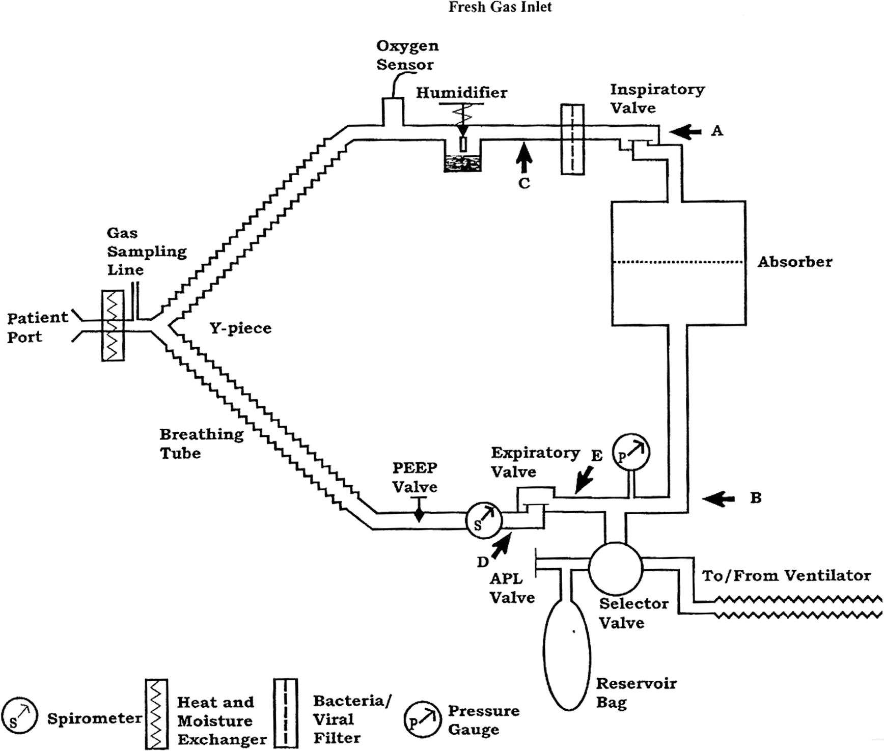
FIGURE 24.7. The circle breathing system is the breathing system used during most general anesthetics. (From Dorsch JA, Dorsch SE, eds. Understanding Anesthesia Equipment. 5th ed. Philadelphia, PA: Lippincott Williams & Wilkins; 2008:239, with permission.)
Ventilator
A critical aspect of the practice of anesthesiology is the ability to ventilate patients. Anesthesia machines integrate the ventilator and its various controls and alarms. If the patient is unable to breathe adequately on his or her own, the ventilator can provide support and enhance the underlying pattern of breathing. If the patient is paralyzed or unable to adequately breathe for other reasons, the ventilator can serve the critical role of ventilation and subsequent oxygen delivery and carbon dioxide removal. The ventilator also serves to deliver and remove anesthetic gases. See Chapter 28, Ventilators, for a further discussion of anesthesia machine ventilators and ventilation modes. A simple distinction between the various ventilation modes is those with which the patient generates a breath vs those generated by the ventilator. The two basic modes of ventilation in which the anesthesia machine generates the ventilation are pressure control (a set pressure is delivered) and volume control (a set tidal volume is delivered). Another major type of ventilation mode involves augmenting a patient-initiated breath with a small amount of positive pressure (pressure support ventilation). This type of ventilation is sometimes combined with backup ventilator-generated breaths. Depending on the type of surgery, the patient, the patient’s comorbidities, and the anesthetic plan, the anesthesia provider will decide which type of ventilation is appropriate for the patient during the surgery.
Scavenging
Scavenging systems remove the waste anesthetic gases from the operating room (see Fig. 24.8). This helps reduce exposure to nitrous oxide and halogenated anesthetic agents, which are potentially hazardous gases. These systems can be broken down into five basic components:

FIGURE 24.8. The scavenging system removes waste gas from the anesthesia machine and out of the operating room.
1. Gas Collection Assembly
The gas collection assembly gathers the excess gas from the ventilator side via the ventilator relief valve and from the manual side via the APL valve. Failure of these valves could lead to a buildup of pressure within the breathing circuit.
2. Transfer Tubing
The transfer tubing carries the gas to the scavenging interface. It is of a specific size and rigidity to prevent easy kinking. If these tubes are blocked or kinked, there can also be a buildup of pressure in the breathing circuit. There is also tubing carrying gas from the gas analyzer to the scavenging interface.
3. Scavenging Interface
The scavenging interface is either an open or a closed system. It protects the breathing circuit from excessive positive or negative pressure. An open interface is open to the atmosphere and has no valves. These are used with active disposal systems. A closed interface has valves to connect to the atmosphere. With passive disposal systems, there is a positive pressure relief valve. With active disposal systems, there is both a positive and a negative pressure relief valve. The positive pressure relief valve prevents the buildup of pressure within the scavenging system and back into the breathing circuit. The negative pressure relief valve prevents the vacuum from emptying out the breathing circuit.
4. Gas Disposal Assembly Tubing
This tubing carries the gases from the scavenging interface to the gas disposal assembly. It is noncollapsible to prevent blockages.
5. Gas Disposal Assembly
The gas disposal assembly is either an active or a passive system, which is the last step in removing the gas from the operating room.
An active system uses a vacuum to induce flow and remove the gas. This can be through the regular suction outlets and couplings or through a waste anesthesia gas (WAG) line with its specific couplings and purple tubing. Two suction lines are typically needed for an anesthesia machine. One is used for patient suctioning equipment and the second for the waste gases. Some older machines only have one suction line, and the negative pressure has to be balanced between the two uses. In active systems, there is an adjustable flowmeter showing the amount of negative pressure present, which should be checked to verify the presence of the vacuum. The gases are usually vented outside the building.
A passive system does not use a vacuum to induce flow. The gases are pushed out through ventilation ducts as more gas flows from the anesthesia machine.
Monitors
Monitors form a critical connection between the patient, the anesthesia machine, and the anesthesia provider. They provide vital information needed to ensure safe care of patients. Monitors are discussed in depth in several chapters of this book. Chapter 30, Gas Analyzers, discusses the gas analyzers used to monitor O2, CO2, N2O, and volatile anesthetic concentrations. Chapter 31, ASA Standard Monitoring, describes the basic monitors typically used during an operation. These monitors include electrocardiogram, which monitors the electrical activity of the heart; the pulse oximeter, which monitors the oxygen saturation of arterial blood; the noninvasive blood pressure; capnography, which monitors the inspiratory and expiratory concentration of carbon dioxide; and temperature. Chapter 5, Cardiovascular Monitoring, discusses more advanced invasive monitoring including arterial blood pressure and central venous pressure.
Another important type of monitor incorporated in the anesthesia machine is a display that contains information about ventilation parameters and error messages from the machine. This functions as a monitor of the anesthesia machine and its various parts, including the ventilator. In fact, there may be significant overlap between this monitor and patient-specific information displayed on a different monitor with the basic and invasive patient monitors. An example of the overlap is the anesthesia machine’s oxygen analyzer, which is displayed on the anesthesia machine’s LCD, and inspired oxygen concentration from the gas analyzer, which is usually displayed on the monitor with the patient’s vital signs. The anesthesia machine ventilator will also have a display for pressures and volumes monitored in the anesthesia circuit (see Chapter 28, Ventilators). In modern anesthesia machines with an LCD, the process of checking out the anesthesia machine usually includes a review of information displayed on this monitor. An understanding of the various machine-related error messages that are displayed is critical for proper machine operation and patient care. Chapter 29, Preventing and Solving Anesthesia Machine Problems, discusses machine maintenance and troubleshooting and reviews common error messages and potential remedies.
Summary
The anesthesia machine is a critical component of the anesthesia work environment. These devices have grown in complexity and now often not only include the components necessary to deliver gas flows and anesthetic agents but come bundled with sophisticated ventilators and monitoring equipment. Anesthesia technicians are intimately involved with working with anesthesia machines, performing machine checkouts, routine maintenance, and troubleshooting. This chapter provides an overview of the basic machine components tracing them from the gas supply through the flowmeters, the vaporizers, the ventilator, and the breathing circuit to the patient and out through the waste gas scavenging.
Review Questions
1. You are scheduled to work at your hospital’s ambulatory surgery center on Monday morning. As you start setting up equipment for the first case, you notice that the anesthesia machine is on and the oxygen is flowing at 10 L/min. You note that the operating room had not been in use since the previous Thursday when the surgery center was last open. What should you do?
A) Turn off the oxygen. Finish setting out equipment for this room and then continue setting up the rest of the rooms for the day.
B) Turn off the machine and the oxygen. Finish setting out equipment for this room and then continue setting up the rest of the rooms for the day.
C) Do not touch the machine. Finish setting out equipment for this room and then continue setting up the rest of the rooms for the day.
D) If the CO2 canister has not changed colors, do not replace it. Finish setting out equipment for this room and then continue setting up the rest of the rooms for the day.
E) Turn off oxygen. Replace the CO2 canister. Finish setting out equipment for this room and then continue setting up the rest of the rooms for the day.
Answer: E
Prolonged fresh gas flows can lead to desiccation or dehydration of the carbon dioxide absorbent. If desiccation is suspected, the absorbent should be changed. Desiccation can sometimes but not always lead to a change in the color of the absorbent. The hazards associated with the use of desiccated absorbent include carbon monoxide formation, compound A formation with sevoflurane, and fire within the canister.
2. At the end of a long operation, a new anesthetist calls you into the operating room. The anesthetist tells you that he is trying to switch volatile anesthetic agents from isoflurane to desflurane but is unable to turn the dial on the desflurane vaporizer to turn it on. He currently has the isoflurane vaporizer on. Both vaporizers are noted to be full of medication. The anesthetist wants to know if he needs a new vaporizer. What should you tell the anesthetist?
A) Yes, the anesthetist needs a new vaporizer. You should be able to turn on both vaporizers at the same time to switch medications.
B) Yes, the anesthetist needs a new vaporizer. There must be a leak in the vaporizer as the anesthesia machine has a safety mechanism that prevents the vaporizer from turning on if there is a leak.
C) No, the vaporizer does not need to be replaced. You explain that there is a safety feature on the anesthesia machine that will not let him switch volatile anesthetics during an operation.
D) No, the vaporizer does not need to be replaced. You explain that there is a safety feature on the anesthesia machine that will not let more than one vaporizer open at a time.
E) No, the vaporizer does not need to be replaced. You tell the anesthetist that if he wants to switch medications, he should just add some desflurane to the sevoflurane vaporizer rather than use a different vaporizer.
Answer: D
The vaporizers are properly functioning. When there is more than one vaporizer present on the anesthesia machine, there is a mechanical link called an Interlink that prevents more than one vaporizer from being opened at a time. This prevents the patient from receiving a simultaneous administration of two volatile anesthetics from the anesthesia machine.
3. The Pin Index Safety System is designed for which purpose?
A) To prevent the gas hose from one gas to be connected to another
B) To prevent the backflow of gas from one cylinder to another
C) To prevent the placement of gas tanks onto the wrong yoke
D) To allow the quick-release connection of gas hoses to the machine
E) To allow any gas tank to be connected to any yoke on the machine
Answer: C
The Pin Index Safety System ensures that each gas tank can only be attached to the specific gas yoke for which it was designed. The Diameter Index Safety System prevents one gas hose from being connected to another. They can only be attached to the specific gas line they are made for. The back-check valves prevent the flow of gas from one tank or gas line into another tank.
4. There are many parts to a scavenging system. Which part listed below is part of an active gas disposal system but not part of a passive system?
A) Ventilator relief valve
B) Rigid transfer tubing
C) Adjustable Pressure-Limiting valve (APL)
D) Vacuum system
E) Positive pressure relief valve
Answer: D
The vacuum system is required for the active scavenging system and provides suction to draw the gases out of the building. The ventilator relief and APL valves allow the excess gas to flow from the breathing circuit to the scavenging interface. The rigid transfer tubing is part of all scavenging systems. The positive pressure relief valve is part of a closed systems design in both active and passive systems.
5. You are called into a room by an anesthetist who complains about smelling volatile anesthetic in the middle of an operation while a patient is intubated and under a general anesthetic. What should you do?
A) Wait until the operation is done before looking for a leak.
B) Look for a hole in patient circuit or disconnect between the patient and circuit.
C) Ensure that the carbon dioxide absorbent canister is properly connected.
D) Ensure that the scavenging system is functioning properly.
E) B, C and D.
Answer: E
The leak of a volatile anesthetic in the middle of the operation is a risk to the patient and all providers in the room. If a significant leak is present, the anesthesia machine should have an audible alarm and an error message displayed on the machine’s screen. There are many sources of a small leak including a hole in the circuit, a hole in the cuff of the endotracheal tube, or a problem with the scavenging system. Each of these should be investigated as appropriate during the operation and double-checked before any subsequent operation.
SUGGESTED READINGS
Barash PG, Cullen BF, Stoelting RK, et al., eds. Clinical Anesthesia. 8th ed. Philadelphia, PA: Wolters Kluwer; 2017.
Dorsch JA, Dorsch SE, eds. Understanding Anesthesia Equipment. 5th ed. Philadelphia, PA: Lippincott Williams & Wilkins; 2008.
Ehrenwerth J, Eisenkraft JB, Berry JM, eds. Anesthesia Equipment: Principles and Applications. 2nd ed. Philadelphia, PA: Elsevier Saunders; 2013.