CHAPTER 37
Intravascular Monitoring Equipment
Introduction
Invasive hemodynamic monitoring is the collection and analysis of quantitative and qualitative data of cardiopulmonary function. It is crucial to anesthetic management during major surgery with large fluid shifts or that of critically ill patients. Fluid-filled monitoring systems attached to intravascular catheters are used for continuous measurement of arterial and intracardiac pressures, as well as for obtaining intermittent or continuous cardiac output measurement. Analysis of arterial and/or mixed venous samples provides pertinent clinical information to the providers for decision-making, including gas exchange, acid-base balance, electrolytes, blood glucose level, and hemoglobin/hematocrit. This chapter will provide the information and instruction of each procedures and associated equipment for arterial line, pulmonary artery catheter (PAC), and blood sampling. For additional information on the physiology underlying these technologies, see Chapter 4, Cardiovascular Anatomy and Physiology, and Chapter 5, Cardiovascular Monitoring.
Arterial Line (A-Line or Art Line)
Definition and Indications
An arterial line is an invasive catheter inserted into a peripheral artery that allows the provider to directly monitor continuous real-time blood pressure changes. This provides beat-to-beat analysis of arterial blood pressure and allows continuous access to blood samples throughout surgery and afterward. The most common site chosen for placement of an arterial line, by far, is the radial artery, given its superficial location and ease of access. Other potential sites include the brachial and axillary arteries in the upper extremities and the femoral, dorsalis pedis, and posterior tibial arteries in the lower extremities (see Table 37.1 for risks and benefits of each location). Umbilical and temporal arteries can be used in neonatal patients.
Table 37.1. Risks and Benefits for Chosen Arterial Line Sites
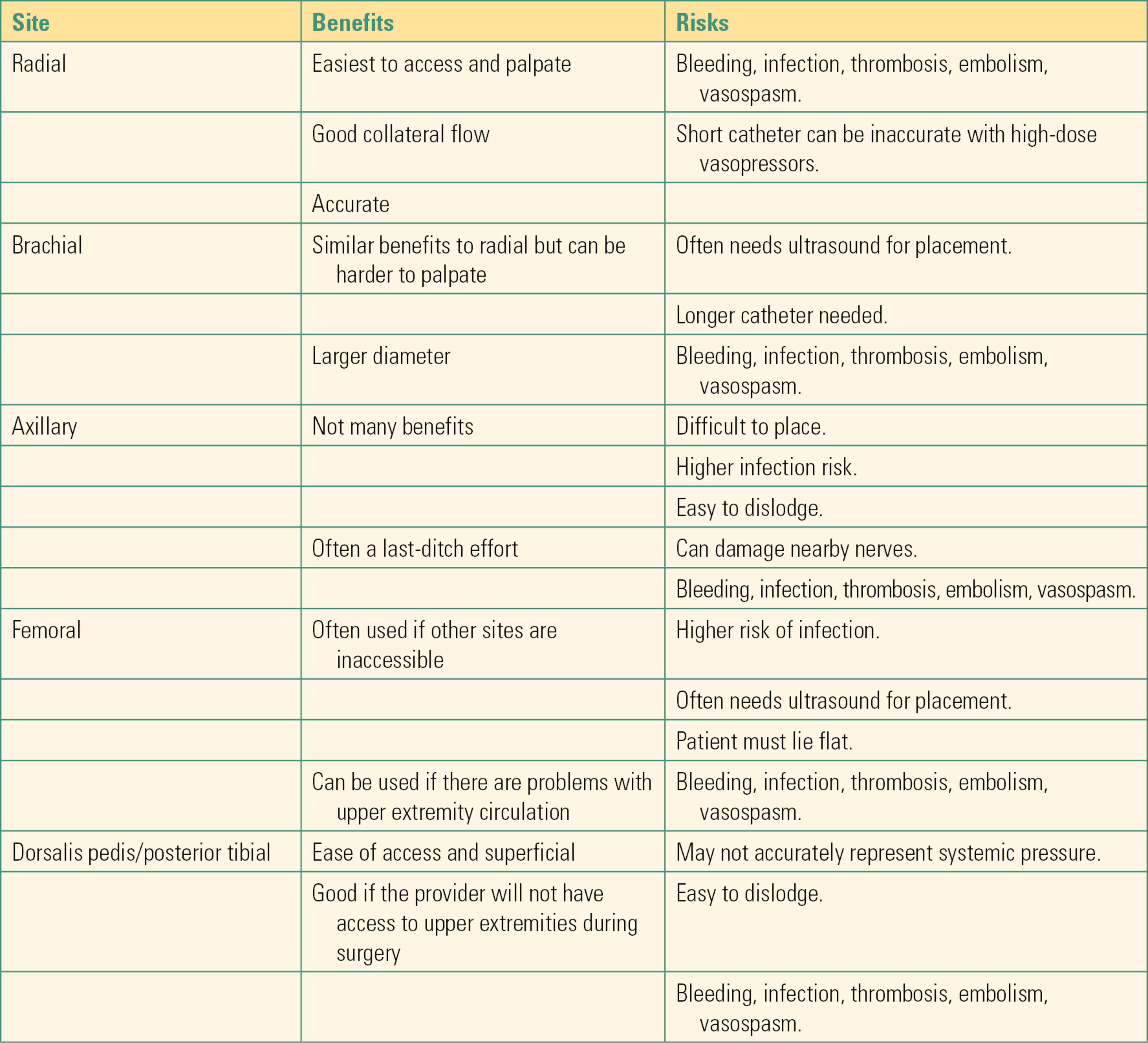
Arterial lines are one of the most frequently placed invasive catheters, and as such, anesthesia technicians require a thorough understanding of why and how they are placed. The following indications for placement, general setup, technique for placement, and troubleshooting tips are general recommendations from our institution. Specific protocols may vary by hospital. The anesthesia technician should be familiar with local protocols for arterial line placement and management.
Indications for Arterial Line Placement
There are multiple indications for the placement of an A-line including, but not limited to:
- Expected frequent or abrupt changes in blood pressure or hemodynamic instability
- Expected large blood loss during surgery
- Frequent need for blood draws (this prevents multiple arterial or venous sticks during surgery)
- The need for titration of vasoactive medications to support blood pressure
- Assessment of a patient’s intravascular volume status (“Systolic Pressure Variation”)
- The need for blood gas monitoring
Contraindications to Arterial Line Placement
- Infection or severe scarring at the site of expected placement
- Coagulopathy or administration of tissue plasminogen activator
- Substantial trauma in the same extremity
- Arteriovenous fistula in the same extremity
Arterial Line Equipment (Fig. 37.1)
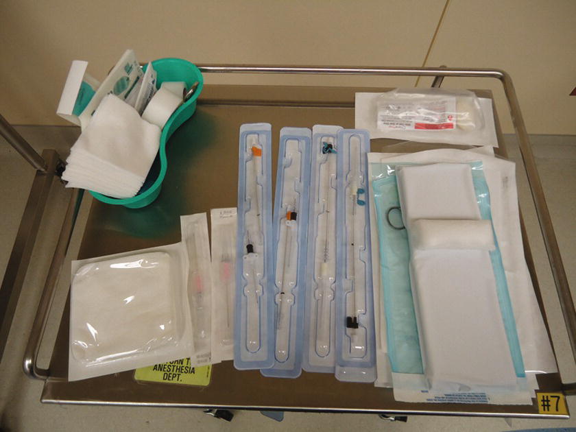
FIGURE 37.1. Arterial line setup: The materials needed for arterial line placement are set up on the mobile cart for ease.
- 20G Angiocath® or Arrow® kit (extra catheters and kits should be immediately available as multiple attempts at cannulation are not uncommon). In addition, smaller catheters may be necessary, particularly in small patients, severe vascular disease, or pediatric patients. For femoral artery cannulation, most institutions have special femoral artery kits that contain a longer catheter, longer access needles, and other supplies (i.e., a guidewire, a dilator, etc.).
- Pressure transducer (compatible cable, IV pole attachment).
- Threadable guidewire (64 mm).
- Rigid pressure tubing with three-way stopcock. Many institutions utilize closed, needle-free, in-line reservoir tubing systems to avoid wasting of patient blood during blood sampling and to decrease the risk of accidental needle puncture. Examples include SafeSet® and VAMP®. Confirm with your institution on its availability (see “Blood Sampling” section for further explanation).
- 500-mL bag of 0.9% sodium chloride. Some institutions utilize heparinized saline (heparin 2 units per milliliter), but it is not standard practice due to increased risk of heparin-induced thrombocytopenia (HIT). Check with your facility.
- Sterile prep (1% chlorhexidine).
- Sterile towels and gauze.
- Sterile gloves (sterile gown is optional in most institutions).
- Mask, eye protection, and cap.
- Arm board attached to operating room (OR) table.
- Wrist immobilizer, tape, or Velcro to secure.
- Pressure bag (capable of at least 300 mm Hg).
- Mobile table for easy access to supplies.
- Clear sterile dressing (e.g., Tegaderm or Opsite).
- Tape.
- Securing supply (for suturing, 2-0 silk sutures and needle driver, scissors, or StatLock®) (Fig. 37.2).
- 1% lidocaine, 3-mL syringe, and 25G or 30G needle.
- Ultrasound machine, sterile sleeve for the probe (ultrasound is used routinely by some providers and only for special circumstances with others). Ultrasound is almost always used for femoral artery cannulations.

FIGURE 37.2. Securing the arterial line with StatLock®.
Arterial Line Technique
- Prepare transducer and monitoring line. For description of the proper setup of pressure transducers, please refer to “Pressure Transducers” section.
- Wash your hands and use gloves before handling or setting up any invasive device.
- Identify the patient using hospital armband, and if able, let the patient confirm his or her identity.
- Confirm with the provider which artery on which extremity will be used.
- Using tape, position patient’s arm on prepared arm board at an abducted position of less than 90 degrees on the OR bed (Fig. 37.3). In some cases, the femoral artery will be used. If so, slightly abduct the leg.
- Clean the wrist of any obvious contamination; then, using sterile prep and sterile technique, clean the arm for at least 30 seconds to 1 minute with enlarging outward circles. Include the area from the patient’s palm up to approximately halfway up the forearm. Be sure to clean both medial and lateral aspects of the hand and arm. If using the femoral artery, prep the groin area from 5 cm above the ilioinguinal ligament to the midthigh.
- Using sterile gloves and towels, drape the patient’s arm exposing only the desired field as shown in Figure 37.4.
- Using sterile technique, open a catheter or catheter/wire kit as well as sterile gauze. Have a guidewire nearby as well.
- Once the provider has successfully cannulated the artery and inserted the arterial catheter, remove the cap from the end of the rigid tubing and hand the provider the tubing without touching the end (Fig. 37.5).
- Confirm the presence of a waveform on the monitor screen.
- If desired by the provider, open and hand in the sterile needle driver and sutures. Or use a catheter securing device, such as StatLock®.
- Zero the arterial line (see “Pressure Transducer” section).
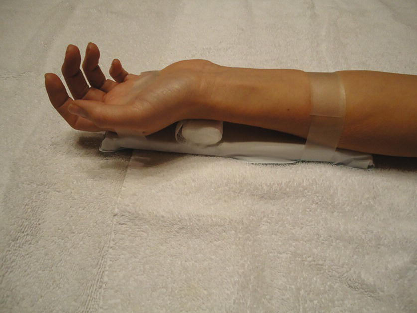
FIGURE 37.3. Preparation for radial arterial line placement. Patient’s upper extremity is secured on the arm board with tape proximally and distally with a roll under the wrist for extension. Supinate the lower arm so that the palm side of the wrist is in horizontal position. Tape the thumb to add more supination if necessary.
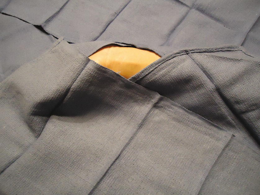
FIGURE 37.4. Draping for radial arterial placement.
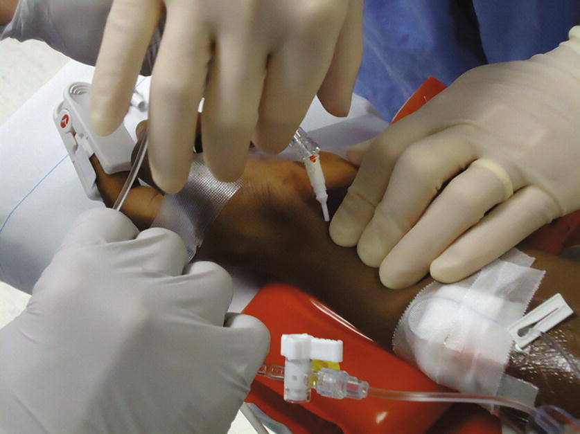
FIGURE 37.5. Connecting the tubing to the radial arterial catheter.
Placement of Arterial Line
Once the proper setup is complete, the provider will place the arterial line by first palpating the chosen artery. After locating optimal pulse, the provider will insert the intended catheter or Arrow kit at a 30- to 45-degree angle until a flash of bright red blood is noted in the catheter. Using the Seldinger technique, leave the catheter in the vessel and withdraw the needle. Once pulsatile flow is noted from the catheter, a wire is threaded into the vessel, and the catheter is advanced over until securely inside the vessel. At this point, the wire is removed, and pressure is placed just past the arterial catheter to avoid outflow of blood. The tubing is then connected to the catheter. Some providers attempt to advance the catheter needle assembly into the artery (specialized arterial line catheters have a self-contained wire that can be advanced at this point). The catheter is then advanced over the needle and into the artery in much the same way as peripheral intravenous line catheters are placed. If the catheter cannot be advanced off the needle into the artery, the catheter/needle assembly is advanced, with the assumption that the operator has passed through the back wall off the artery. The needle is removed and the catheter is withdrawn as described above. When pulsatile flow is obtained, a wire is passed into the artery and then the catheter can be advanced over the wire into the artery. The wire can then be removed. Pulsatile flow should still be present. Securely attach the monitoring tubing to the catheter hub and check the monitor for an arterial waveform.
For femoral arterial lines, the same basic technique is often utilized, with the exception that it is more common to use ultrasound to locate the artery. Prepare the ultrasound machine and probe as described in the section on central venous access. Prep and drape the patient as described above. The operator will attach a syringe to a needle and advance the needle under ultrasound guidance or by palpation into the artery. The syringe will be removed and pulsatile flow confirmed. A wire is passed into the artery and the needle removed. The specialized long arterial catheter can then be advanced over the wire and into the artery. The wire is removed and pulsatile flow is confirmed. The remaining steps are the same as those described for cannulation of the radial or brachial artery in the arm.
Arterial Waveform Basics
The exact morphology of an arterial waveform can explain much about the arterial line setup, patient pathology, and hemodynamics. See Figure 37.6 for an example of a normal arterial waveform. The normal initial upslope indicates early systole with the opening of the aortic valve and left ventricular contraction. The peak (A) indicates runoff after ventricular contraction and occurs during midsystole. The typical notch seen on the downward slope (D: dicrotic notch) indicates the closure of the aortic valve and indicates the beginning of diastole. The final downward slope indicates further diastole. Common variations in waveforms include both overdampening and underdampening. In a very simplistic sense, overdampening occurs when the transducer cannot sense the pulsation clearly. The waveform tracing will be flattened with a much smaller difference between systolic pressure and diastolic pressure. This can be due to kinked tubing or a kinked catheter, closed or partially closed stopcocks, flexed wrist, air bubbles or clots in the tubing, overdistensible tubing, underpressurized IV bag, vasodilation, or the catheter being up against the wall of the artery. This results in underestimation of blood pressure. Similarly, underdampening is an exaggerated peaked waveform that can overestimate blood pressure. This can be due to excessive tubing length, overly rigid tubing, or vasoconstriction. Further explanation of waveform variation can be found in Chapter 5.
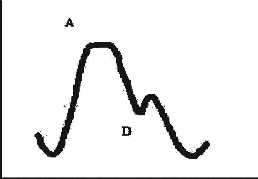
FIGURE 37.6. Arterial pressure waveform. A, Peak (Systolic) arterial pressure; D, dicrotic notch.
Arterial Line Complications
Commonly cited complications can include bleeding, hematoma, and infection. It is critical to secure the tubing to the catheter as patients can lose blood upward of 500 mL/min if an arterial line becomes disconnected. Potential, but less common, complications include damage to nearby structures (veins, nerves, tendons, etc.), decreased hand perfusion, air embolism, thromboembolism, and even compartment syndrome with hidden bleeding.
Arterial Line Troubleshooting
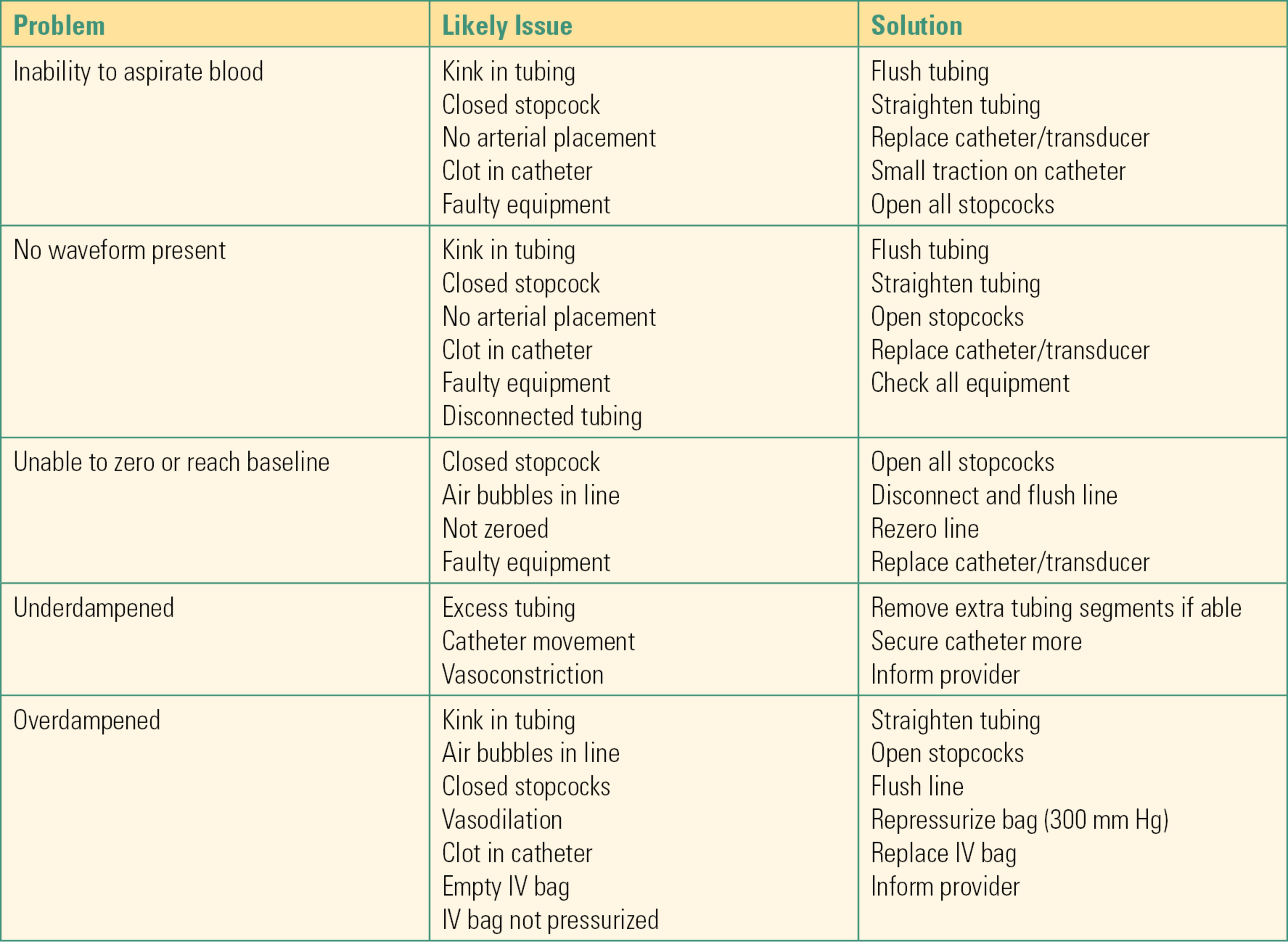
Common conditions and troubleshooting tips are included in Table 37.2. Other items to consider include the following:
Table 37.2. Troubleshooting for Arterial Line
- If the patient is awake, always introduce yourself and explain what you are doing and why.
- The site chosen for the catheter can be influenced by the surgical procedure, ease of access, and, in some cases, patient safety. Confirm the site with the provider prior to setup.
- Examine the arm for evidence of infection, trauma, existing vascular access, and arteriovenous fistulas prior to preparing the region. Miscommunications between the provider and the anesthesia technician can occur. If you observe a potential contraindication for placement of the arterial line in the location you are preparing, discuss the issue with the provider.
- If the patient is alert and oriented, it can be helpful to ask about his or her handedness (which hand he or she brushes his or her hair or teeth with, etc.). It is more comfortable for the patient in the postoperative period if the catheter is placed in the nondominant arm.
- Do not hyperextend the wrist if the radial artery is chosen as this can induce radial nerve injury.
- Check for capillary refill in the region distal to the catheter after insertion to ensure continued perfusion.
- Arterial line transducers need to be changed out every 96 hours.
- Change catheter to 22G in pediatric patients and 24G in the neonatal population.
Pulmonary Artery Catheter
Definition and Indications
The pulmonary artery catheter, also known as the Swan-Ganz catheter named after its inventors, was introduced in 1970 and now is widely used as a diagnostic and monitoring tool in the management of critically ill patients. The PAC is a balloon flotation catheter. It has a small balloon on its tip that is inflated after insertion and floats the catheter along with the blood flow through the vena cava into the right heart. The PAC is then further advanced into the pulmonary artery (PA). If balloon flotation is unsuccessful, it can be placed with fluoroscopy or ultrasound at the bedside.
Basic features of PACs are illustrated in Figure 37.7. The length of the catheter is 110 cm, and the diameter is 7-8 French depending on the number of lumens and additional features. The basic catheter has at least three lumens, a distal port near the tip, a proximal port 30 cm from the tip, and a port for inflating the balloon. Inflation of more than 3 mL of air into the balloon port can rupture the balloon. It is important not to confuse the ports and inadvertently attempt to inject medications or fluids through the balloon port. In addition to the ports, there is a thermistor (transducer that senses the temperature) 4 cm from the tip of the catheter. The newer catheters are equipped with more features such as an extra lumen for infusion or passing temporary pacemaker leads into the right ventricle (RV) (opens at 14 cm from the tip) and a fiberoptic system that allows continuous monitoring of mixed venous oxygen saturation.
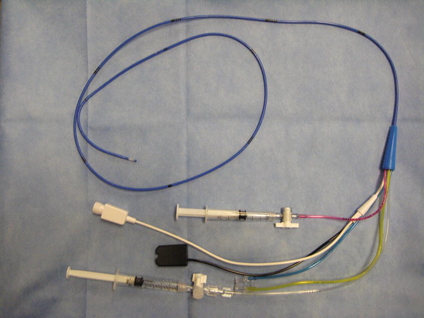
FIGURE 37.7. Pulmonary artery catheter. This photograph shows Hospira Opticath® thermodilution pulmonary artery catheter. The blue port is the proximal port, the yellow is the distal port, and the clear is the infusion port. The red tube has a locking system for inflating/deflating the balloon. This catheter is equipped with a fiberoptic cable to measure mixed venous oxygen saturation (black) and a thermistor (white) for measuring cardiac output by thermodilution technique.
PAC functions include the following:
- Direct measurement of right atrial pressure (CVP), right ventricular pressure, and pulmonary arterial pressure.
- Indirect assessment of left atrial pressure via the pulmonary artery occlusion pressure (PAOP) (also called pulmonary artery wedge pressure: PAWP). This measurement is obtained by properly positioning the catheter in a branch of the PA and temporarily inflating the balloon while the measurement is taken.
- Measurement of cardiac output by thermodilution and hemodynamic calculation.
- Mixed venous blood sampling.
Because of the potential complications associated with PACs (see below) and the introduction of transesophageal echo to monitor heart function, the indications for placement of PACs have diminished. Commonly accepted indications include the following:
- Management of complicated acute myocardial infarction with cardiogenic shock
- Management of acute decompensation in severe heart failure
- Management of noncardiogenic shock
- Diagnosis of pulmonary hypertension
Contraindications include the following:
- Mechanical prosthesis in tricuspid or pulmonary valve
- Tricuspid or pulmonary endocarditis
- Presence of right heart mass
It is critical to have a latex-free catheter for a patient with latex allergy.
PAC Equipment
Although placing the PAC is not complicated and easily done at the bedside, appropriate training and equipment are required.
- All equipment needed for central venous catheter (CVC) insertion as previously described.
- Two pressure transducers (or three including one for arterial pressure) so that pressure can be monitored in both the proximal and distal port (Fig. 37.8).
- Introducer kit (8.5-9 French) (Fig. 37.9).
- PAC.
- Thermodilution set (a bag of saline, injector, tubing) and cardiac output cable.
- Resuscitation equipment and external pacing device (in the event of vascular complications or life-threatening arrhythmias during insertion) (see complications below).
- Consider placing transcutaneous pacing/defibrillating pads on patients with existing cardiac conduction abnormalities or tachyarrhythmias; the PAC can cause arrhythmias, most commonly as it passes through the right ventricle (RV).
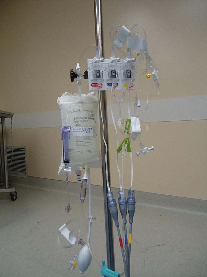
FIGURE 37.8. Triple-pressure transducer. Each transducer is color coded. The most left is for arterial line (red), the middle is for central venous pressure (blue), and the most right is for pulmonary artery pressure (yellow).
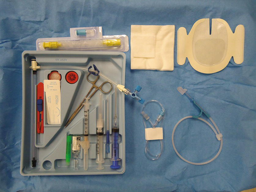
FIGURE 37.9. Sheath introducer kit. The kit contains a 9-French sheath introducer, a dilator, a stopcock and caps, a manometry tubing, syringes, needles, a guidewire, a suture kit, a blade, gauze, dressing, 1% lidocaine (5-mL ampoule), a sterile cover, and a hub cap. Some kits also contain chlorhexidine preps and a full-body drape.
Technique for PAC Insertion
1. Determine the insertion site: The PAC is inserted most commonly in the internal jugular vein (IJV) or the subclavian vein (SCV) as the course of venous return to the right atrium (RA) is more straightforward from these insertion sites. In the cardiac catheterization lab, where fluoroscopic guidance can be used, the femoral vein (FV) is often accessed for right heart catheterization.
2. Position the patient properly and obtain central venous access with an 8.5-French or a 9-French introducer as described above (Central Venous Access section in Chapter 36).
3. Once access is obtained, the operator will remain sterile and an assistant will perform nonsterile tasks. Just prior to the insertion, prepare the PAC. See Video 37.1. If it is equipped with a fiberoptic system for continuous mixed venous O2 saturation, connect the cable to the module and perform preinsertion calibration. Remove the PAC from the plastic packet and connect the thermodilution cable to the thermistor port. Check for the temperature to display on the monitor screen (should be room temperature before PAC insertion). Place the sterile cover over the catheter and lock it at 100 cm. Connect the pressure tubing from the transducers to each port on the PAC and flush with saline (the distal port [yellow] is for PA pressure; the proximal port [blue] is for CVP). If the PAC has an infusion port, connect a stopcock and a 3-mL syringe to the port and flush with saline. Lastly, inflate the balloon with 1.5 mL of air using the syringe provided in the kit (the syringe is equipped with a lock system to prevent overinflation of the balloon) (Fig. 37.10A). Check to see that the balloon has inflated evenly. Deflate the balloon by releasing the syringe plunger. Do not aspirate on the plunger to deflate the balloon. Most PACs have a mechanism to lock the balloon port to keep the balloon inflated (Fig. 37.10B).
4. The operator is now ready to insert the catheter. Place the patient back to flat or in slight reverse Trendelenburg position. Slightly tilt the table to the right. This position assists the operator in floating the PAC into the PA. The operator inserts the catheter through the introducer up to 20 cm. Inflate the balloon slowly with 1.5 mL of air and lock the syringe. You should not feel resistance. If you do, stop inflating and notify the provider. Check the monitor for a central venous waveform. As the catheter is advanced into the RV, the pressure waveform will change as shown in Figure 37.11.
5. After advancing the PAC 30-35 cm in a normal size adult, the catheter tip will enter the RV through the tricuspid valve. A pulsatile RV systolic pressure appears. The diastolic pressure is still equal to the RA pressure. Record the RV systolic and diastolic pressures.
6. When the catheter is advanced across the pulmonic valve into the PA, the diastolic pressure rises, whereas the systolic pressure remains unchanged. This occurs at around 45-50 cm in normal size adults. Record the PA systolic and diastolic pressures.
7. The catheter is then slowly advanced in the PA until the waveform changes again where the systolic pressure disappears and the waveform resembles the RA pressure waveform. This pressure is known as the pulmonary artery capillary wedge pressure (PACWP) or the PAOP. At this point, the operator will stop advancing the catheter. Record the pressure and then deflate the balloon by unlocking the syringe. Make sure that the same amount of air (1.5 mL) returns to the syringe without aspiration. If the air does not return, it can be a sign that the balloon has ruptured. The balloon should be deflated at all times while the PAC is left in place in the PA (prolonged inflation can cause PA rupture). Balloon inflation should be reserved for the measurement of PAWP. Inflate the balloon slowly until a wedge pressure tracing appears on the monitor screen. This can occur before the balloon is fully inflated. The catheter can migrate distally into a smaller portion of the artery. Overinflation can cause rupture of a PA. After the PAWP is recorded, the balloon should be deflated.
8. Stretch the sterile cover toward the hub of the introducer and lock it over the hub. Lock the catheter by twisting the locking system on the cover to secure the catheter position.
9. Apply the sterile transparent dressing at the insertion site (Fig. 37.12).
10. The catheter has multiple ports with multiple tubes and cables connected. The weight of these devices can pull on the catheter and dislodge it. To prevent this, secure the proximal end of the PAC with a securing device or clamp (use caution so that you do not clamp the catheter).
11. As noted above, the balloon should be deflated at all times while the PAC is left in place in the PA. The balloon inflation should be reserved for measurement of PACWP. After the PACWP is recorded, the balloon should be deflated.
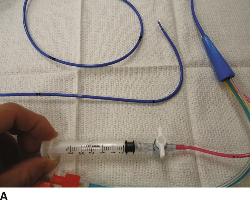
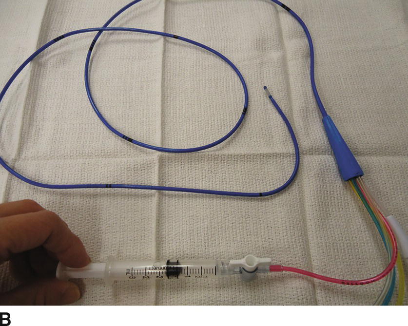
FIGURE 37.10. A: Inflating the balloon. The balloon at the tip of the catheter is fully inflated with 1.5 mL of air. Note that the syringe is locked. B: Deflating the balloon. The balloon is deflated when the syringe is unlocked and 1.5 mL of air is back in the syringe.
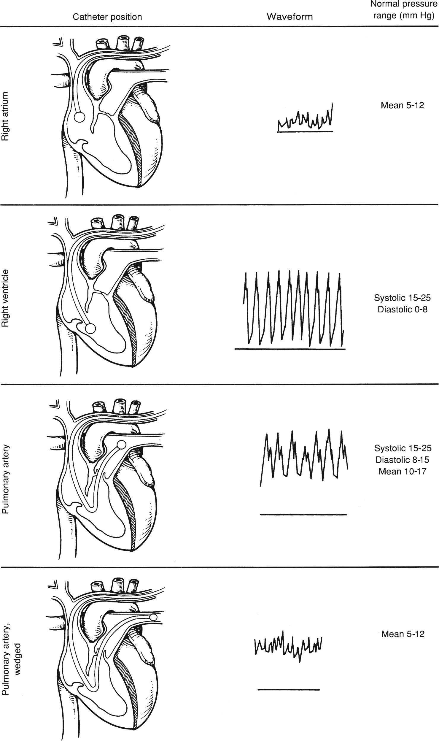
FIGURE 37.11. Change in the pressure waveform correlates with the position of the tip of the pulmonary artery catheter.
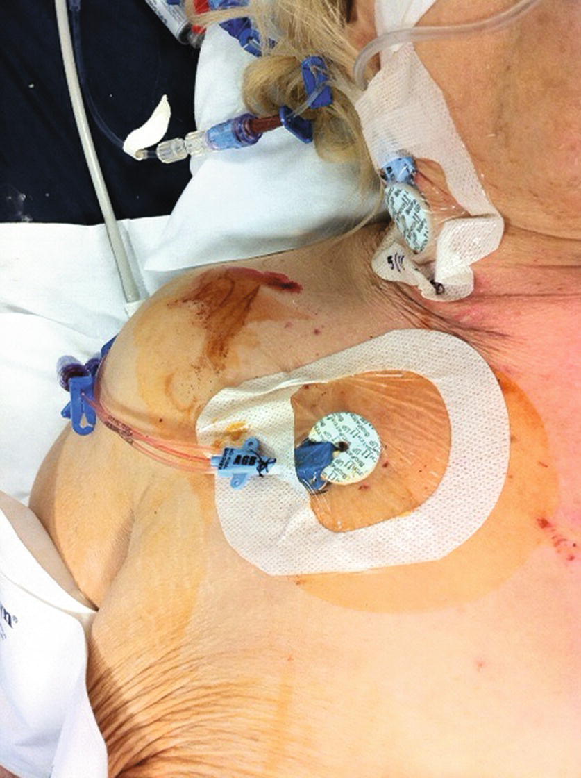
FIGURE 37.12. Applying a sterile dressing over the central line insertion site.
Cardiac Output Measurement (by Thermodilution Technique) (Also See Video 37.2)
1. After the PAC is inserted, connect the thermodilution kit to the injection port (the proximal port: blue) at the stopcock (Fig. 37.13), making sure that there is no air in the fluid bag and the tubing (deairing the bag and tubing should be done prior to connecting). Stop the fluid infusion from the side port of the introducer to avoid a temperature change. Infusion of cold fluid through the infusion port will interfere with cardiac output measurements.
2. Connect the cardiac output cable to the thermistor of the PAC and injectate temperature port of the thermodilution kit.
3. Activate the cardiac output window on the monitor screen. To calculate cardiac index, you need to enter patient’s height and weight or body surface area (BSA). Enter the constant value specific for the PAC used. Draw the fluid in the syringe, normally 5 or 10 mL, depending on the characteristics of the catheter (see the insert in the package for the constant value and the amount of the fluid).
4. Press the “Start” button on the monitor. After the beep and the prompt on the monitor screen (“Inject now!”), inject the entire amount of fluid in the syringe quickly but at a steady rate. Changes in speed or volume produce errors in the measured value. You will see the curve of the temperature change on the screen.
5. Wait for the monitor to come back to “Ready” before performing the next measurement.
6. Perform three cardiac output measurements and record the average value.
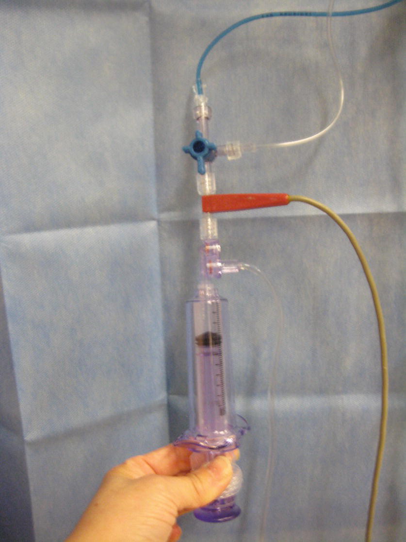
FIGURE 37.13. The thermodilution kit connected to a pulmonary artery catheter.
PAC Complications
The complications related to PAC placement include the complications related to CVC access as described above. PAC-specific complications are listed below:
- Arrhythmias: Atrial or ventricular arrhythmias are the most common complications while placing or removing the catheter. The catheter can touch the endocardium and irritate it. Arrhythmias are normally transient and do not need intervention; however, in some cases, the arrhythmias can be serious (i.e., complete heart block or ventricular tachycardia/fibrillation) and require urgent treatment.
- Complete heart block: Transient right bundle branch block (BBB) after PAC placement occurs in about 5% of patients and is usually not hemodynamically significant. However, complete heart block can occur in the patients with pre-existing left BBB and may require cardiac pacing.
- PA rupture: This is very rare but a catastrophic complication that carries a mortality rate of 50%-70%. Risk factors include pulmonary hypertension, hypothermia, and overinflation of the balloon. To minimize the risk, avoid overinflating the balloon and minimize PAWP measurements.
- Pulmonary infarction: Overwedging of the catheter (prolonged balloon inflation) or overinflation of the balloon can cause pulmonary infarction. Prolonged inflation of the balloon usually occurs when a PAWP measurement was taken and deflation of the balloon was forgotten.
- Catheter knotting: During insertion of the catheter, coiling of the catheter occasionally occurs in the cardiac chambers. This can lead to knot formation. If the catheter does not advance to the next chamber at the expected length, it should be pulled back with the balloon deflated. Risk factors for knotting include a large RV; multiple attempts at passing the catheter into the PA; a warm, flexible catheter; and other indwelling devices (i.e., CVCs, pacemaker leads, IVC filters).
- Tricuspid and pulmonary valve injury: Mechanical damage to the cardiac structure, such as valve leaflets or chordae tendineae, can occur during PAC placement, manipulation, or removal, resulting in valvular regurgitation, although it is uncommon. Mechanical complications and catheter knotting appear to be associated with difficult placement.
PAC Troubleshooting
- Cannot see the venous waveform: Make sure that the pressure transducers are connected to the correct ports and all transducers are zeroed. When any questions arise, withdraw the catheter and recheck by flushing each port.
- On the inflation of the balloon, there is excessive resistance and very high pressure appears on the monitor: This could be caused by inflating the balloon in the sheath. Let the balloon deflate and advance the catheter to 20 cm. If it happens at 20 cm, the tip might be against the vessel wall. Deflate the balloon and reposition the catheter by rotating.
- The catheter will not advance into the RV or the PA: Position the patient in reverse Trendelenburg position and slightly tilted to the right. Perform a Valsalva maneuver followed by release. This promotes the forward flow of blood in the right heart and can help float the catheter through the right side of the heart. Alternatively, temporarily increasing ventricular contractility by administering an inotropic agent may help advance the catheter into the PA. If still unsuccessful, transesophageal echocardiography may be helpful in guiding the catheter. In rare circumstances, fluoroscopy is necessary.
- Unable to obtain a wedge pressure: In some patients, a typical PACWP waveform does not appear even at the maximum depth (60 cm in normal size adult). The observed waveform could be a prominent v wave from significant mitral regurgitation or simply caused by nonuniform inflation of balloon, but the true cause is unknown in many cases.
Pressure Transducers
A pressure transducer is a device containing a fluid-air interface that converts fluctuations in pressure to electronic data, which is then displayed on the patient monitor. The transducer contains a diaphragm with a silicon chip that continuously translates the pressure against the diaphragm from the column of fluid between the transducer and the patient’s circulation. The continuity of the fluid column is essential to proper functioning of the transducer, and as such, any air bubbles, clots, or kinks in the tubing will cause inaccurate reporting of pressure changes (overdamping).
Also key to obtaining accurate information is properly “zeroing” the device. Gravity and the weight of the fluid in the column pressing against the diaphragm (if the fluid column is above the transducer) or pulling away from the diaphragm (if the fluid column is below the transducer) can affect pressure readings. To control this effect, the transducer should be placed at the same height as the point in the body that will serve as the reference pressure, a point called the phlebostatic axis. For operations with the patient in the supine position, the phlebostatic axis is the point at which the fourth intercostal space intersects with the midaxillary line in order to use the RA as a reference point (zero level). It is important to maintain this relationship between the patient and the reference point. When the height of the operating table is changed, the transducer height will have to be changed as well. Small variations in the height of the transducer compared to the reference point will create inaccurate values in the measured pressure. Transducers can be used in the hospital to monitor a variety of pressures, including central venous blood pressure, arterial pressure, PA pressure, tissue compartment pressure, and even intracranial pressure.
Setting Up a Pressure Transducer (See Video 37.3)
- Connect the rigid tubing to the patient end (top) of the pressure transducer; also insert a three-way stopcock near the patient end of the tubing for blood sampling. If using VAMP®, SafeSet®, or another in-line reservoir, ensure that the in-line reservoir is connected to the patient end of the pressure transducer (Fig. 37.14).
- Connect the flexible tubing with the bag spike to the appropriate connection on the pressure transducer (bottom).
- Spike a normal saline or heparinized saline bag. Insert the fluid bag into the pressure bag and pressurize it to 200-250 mm Hg. Fill the drip chamber up to two-thirds of the capacity by squeezing the chamber a couple of times (Fig. 37.15).
- Prime the entire tubing length with fluid by gently pulling on the red rubber tag or squeezing flush valve on the pressure transducer. If unable to prime, ensure all stopcocks and valves are open to the tubing.
- VAMP® and SafeSet® systems often come preassembled, and you simply need to spike the IV bag and prime the tubing as above.
- It is crucial to thoroughly flush the entire tubing and ensure there is no air in the tubing as this can lead to severe patient complications. Periodically flick tubing and stopcocks with finger to release and remove any extra air bubbles.
- Ensure arterial line transducer is attached to an IV pole at a point level with the phlebostatic axis.
- Certain arterial line tubing sets come with stopcock caps with holes in them that, when placed on the pressure transducer stopcock, allow for zeroing of the transducer without removal of the cap. It is important to ensure that these caps are only on the pressure transducer stopcock and not on the blood sampling stopcock near the patient end. If so, please replace with an occlusive cap.
- If asked to set up multiple invasive lines/monitors, you will need a holder for multiple pressure transducers, as well as a single pressurized saline bag with the properly spiked flexible tubing (i.e., use 2:1 split tubing for an arterial line and CVP and 3:1 split for adding a PAC). Make sure to label each pressure transducer with the corresponding line it represents. Ensure that all lines and tubing are again properly flushed and contain no air.
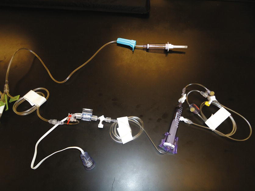
FIGURE 37.14. Arterial line transducer and tubing (SafeSet®).
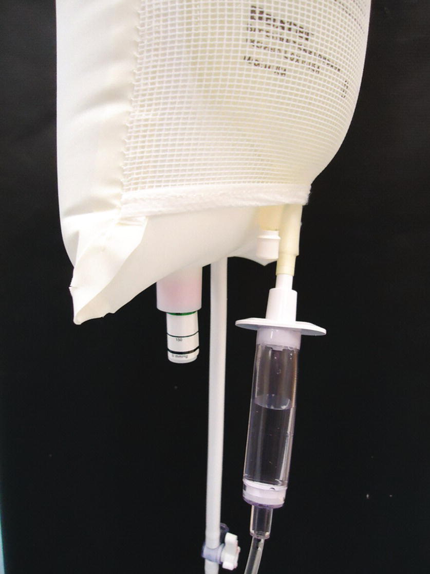
FIGURE 37.15. Fluid-filled drip chamber for pressure transducer to 250 mm Hg (green line).
Zeroing the Pressure Transducer
1. Set the transducer to the desired height in relation to the reference point (in some cases, the provider may want to use a different reference point than the RA—ask the provider if you are unsure).
2. With the transducer patient tubing connected to the catheter, open the pressure transducer stopcock to the air. Then, press the “Zero” button on the monitor setup. Press the button appropriate for the line for which you are performing the zero. For example, for arterial lines, press “Zero ABP” button.
3. At this point, the waveform should be flat. The numeric value on the monitor should read “0,” and most monitors provide an audible alert to indicate that the zeroing process is complete. Close the stopcock, positioned in a way that the transducer is open to the patient side. The waveform will reappear and give a digital display of the pressure.
Blood Sampling
One of the benefits to placing an arterial line is that it allows repeated sampling of blood for arterial blood gases and other laboratory tests. With the proper technique, the patient risk associated with blood sampling will be minimized. Blood samples need to be drawn into tubes containing heparin or other anticoagulants to prevent clotting, unless otherwise specified for that particular test. For arterial blood gas samples, syringes that are preheparinized can be used, or a small amount of heparin can be drawn up into a 1- to 3-mL syringe, coating the inside of the tube, and then squirted out. Of note, sterile procedure and universal precautions should be followed for all blood sampling.
Withdrawing the blood sample in an open sampling set:
1. Remove sterile cap from stopcock and wipe port with alcohol swab for 30 seconds.
2. Attach 5- or 10-mL regular syringe to the port.
3. Turn the stopcock off to the flush/transducer.
4. Withdraw 5-10 mL of patient blood into syringe, and then close the stopcock at 45-degree angle to prevent flush from flowing to the patient (to avoid dilution of the sample, withdraw at least two times the dead space volume).
5. Discard the waste syringe (the sample is diluted with flush solution) and attach an appropriately sized syringe to the stopcock (blood gas samples must be drawn into heparinized syringes).
6. Again turn the stopcock off to the flush and withdraw 1-3 mL of blood for the sample.
7. Close the stopcock to the port and cap the sample syringe. Replace the sterile cap on the port.
8. Pull the red rubber pigtail to flush the tubing until it is clear. Make sure to pull the red pigtail for only 2-3 seconds at a time, and repeat after a couple of seconds as needed to clear the line. Flushing the line for more than 3 seconds can push fluid back into the proximal arterial circulation as far as the aorta (or cerebral circulation in pediatric patients). Proper flushing of the tubing should require no more than one or two short pulls on the pigtail. If this is not clearing the tubing, ensure the saline bag is properly pressurized.
9. Confirm the presence of a waveform.
Withdrawing blood in a closed sampling set (VAMP®, SafeSet®) (see Video 37.4)
1. When utilizing an in-line sampling set, a blunt tip needle is necessary for the heparinized syringe.
2. The SafeSet® system comes with an in-line syringe that collects the “discarded blood” into a 10-mL syringe. Five to ten milliliters of patient blood (at least two times the dead space volume) is slowly withdrawn into the syringe, and the stopcock at the end of the syringe is closed.
3. After cleansing the closest SafeSet® port to the patient with alcohol, the blunt needle is inserted into the port and blood is removed for the sample.
4. The syringe stopcock is then opened and the prior “discarded blood” is injected back into the patient, and the red rubber pigtail is pulled to flush the line until clear. Again confirm the presence of an appropriate waveform.
Withdrawing a sample from a PIV catheter:
After placing a PIV catheter, venous blood sample can be obtained from the catheter before releasing the tourniquet and the infusion set is connected. After an infusion is started, a blood sample can also be obtained from a PIV catheter or central access catheter by the following procedure; however, small veins can collapse and blood sampling may not be possible in those circumstances.
1. Stop all infusions at least 1 minute before sampling to avoid dilution. Make sure that the clamp flow through the IV is closed.
2. Apply a tourniquet proximal to the IV insertion site if the sampling site is from a PIV catheter. If the blood pressure cuff is applied on the extremity that has the PIV catheter, the “Venipuncture mode” of the automated noninvasive blood pressure machine can be used.
3. Attach a 10- to 20-mL syringe to the closest (to the catheter) stopcock or injection port and slowly withdraw at least four times the dead space volume.
4. Discard the waste syringe and attach the sampling syringe (5-10 mL). Take caution not to apply excessive negative pressure as this will cause hemolysis of the sample.
5. Collect the blood sample needed for the test.
6. Release the tourniquet and turn off the “Venipuncture mode.”
7. Open the regulating clamp and flush the blood in the tubing with IV fluid.
Summary
Placing invasive monitoring lines is a very common practice in perioperative and critical care settings and one in which you as an anesthesia technician will frequently assist. Anesthesia technicians should be familiar and well trained for preparing the necessary equipment, assisting providers to place these lines, troubleshooting, and recognizing potential complications.
The proper technique for obtaining blood samples as well as performing the cardiac output measurements is also described here. In addition to these techniques, adherence to institutional policies for sterile technique is imperative.
Review Questions
1. Which artery is not appropriate for placement of an arterial line?
A) Radial artery.
B) Femoral artery.
C) Dorsalis pedis artery.
D) Axillary artery.
E) Temporal artery.
F) All of the above are appropriate.
Answer: F
Most commonly used artery for the placement of arterial line is, by far, radial artery due to the ease of access. Other superficial arteries are also used when radial arteries are not accessible. Brachial arteries are not a preferable option due to higher risk of limb ischemia from thrombosis. Dorsalis pedis, femoral, and axillary arteries are the second options. Temporal arteries can be used in neonates.
2. Which of the following is not a contraindication for arterial line placement?
A) Arteriovenous fistula in the same extremity
B) History of axillary lymph node dissection on the same side
C) Infection or severe scarring at the site
D) Coagulopathy or administration of tissue plasminogen activator
E) Substantial trauma in the same extremity
Answer: B
History of ipsilateral (the same side) axillary lymph node dissection is not contraindication to the placement of arterial line. Severe coagulopathy is a relative contraindication, especially for femoral artery or axillary artery due to difficulty in hemostasis. Infection and trauma in the same extremity are also contraindications, and the site/extremities should be inspected carefully prior to placement.
3. Which of the following is (are) potential complication(s) associated with arterial line placement?
A) Infection
B) Bleeding/hematoma
C) Thrombosis/limb ischemia
D) Nerve injury
E) All of the above
Answer: E
The risk of thrombosis/limb ischemia is associated with the size of the catheter and the artery. Brachial artery should be best avoided due to the higher risk of limb ischemia.
The majority of blood stream infection associated with arterial line is acquired extraluminally from the skin, and chlorhexidine for cutaneous antisepsis is shown to be beneficial for its prevention.
Radial nerve injury associated with radial arterial line is rare and mostly transient. When paresthesia is encountered during or after the placement, the catheter should be removed immediately.
4. Which of the following cannot be obtained by placing a pulmonary artery catheter (PAC)?
A) Right atrial pressure (central venous pressure)
B) Right ventricular pressure
C) Left ventricular pressure
D) Pulmonary artery pressure
E) Cardiac output
Answer: C
The parameters that can be obtained directly by placing a PAC are:
Right atrial pressure
Right ventricular pressure
Pulmonary arterial pressure
Pulmonary artery wedge pressure (represents left atrial pressure)
Cardiac output
With a special catheter, mixed venous oxygen saturation (SVO2) and continuous cardiac output (CCO) can be also obtained.
Left ventricular pressure cannot be obtained from PAC.
5. Which of the following is true regarding setting up or using a transducer for an arterial line?
A) Bubbles in the line can cause a venous embolus.
B) The drip chamber should always be in the upright position.
C) Damping of the signal will cause an overestimation of blood pressure.
D) When flushing the line into the patient, hold the pressurized flush open for at least 6 seconds.
E) The femoral artery should never be used for an arterial line.
Answer: B
The drip chamber of the pressurized flush should be kept in the upright position to prevent air from entering the line to the patient. Bubbles in the line could cause an embolus in the artery and not the vein. In addition, bubbles in the line could dampen the signal (flatten the waveform), leading to an underestimation of the blood pressure. When flushing the line with pressurized fluid, the flush should not be applied for more than 3 seconds to prevent flush from reaching the central arterial circulation. The femoral artery is commonly accessed for arterial pressures.
6. Which of the following statements are false in regard to zeroing a transducer?
A) The transducer should be opened to air to perform zeroing.
B) It is necessary to press a button on the monitor to initiate zeroing.
C) Zeroing is not necessary the first time you set up and use a pressure transducer.
D) The monitor should read “0” when the transducer is open to air.
E) All of the above are false.
Answer: C
Every time you set up a transducer, it must be zeroed. In addition, when the transducer cable is disconnected, the transducer may have to be rezeroed. To perform a zero, the transducer is opened to air, and the monitor button for that particular line is pressed until the monitor reads “0.”
7. Which statement is true in regard to performing the cardiac output measurement?
A) Connect thermodilution kit to distal (yellow) port, making sure to deair the fluid bag.
B) To calculate body surface area (BSA), thus cardiac index (CI), the weight and the height of the patient are needed along with a computation constant specific for the catheter in use.
C) One measurement of cardiac output is appropriate if the value is similar to the previous measurement.
D) Cardiac output measurement can be performed during cardiopulmonary bypass.
E) The cardiac output measurement with the use of PAC by the change of temperature of injectate is called the “Fick principle.”
Answer: B
The cardiac output measurement using PAC from the change in temperature of injectate is called “thermodilution technique.” Cardiac index (CI) is calculated from cardiac output (CO) and BSA (CI = CO/BSA). BSA is calculated by a complex formula using weight and height. A thermodilution kit should be connected to the proximal (blue) port. Cardiac output values can change from multiple factors. It also can vary from beat to beat in the setting of arrhythmias. The average value should be obtained from at least three consecutive measurements or more in the presence of arrhythmias. The Fick method is an alternative method which you will sometimes hear being discussed. This can use mixed venous oxygen saturation to calculate an approximated cardiac output.
8. Which is the correct intracardiac path of the PAC during its placement?
SVC, superior vena cava; IVC, inferior vena cava; RA, right atrium; LA, left atrium; RV, right ventricle; LV, left ventricle; PA, pulmonary artery.
A) RV → RA → SVC → PA
B) RA → LA → LV → PA
C) SVC → RA → RV → PA
D) IVC → RV → RA → PA
E) LA → RA → RV → PA
Answer: C
Correct intracardiac path of the PAC during its placement is:
SVC (or IVC) → RA → RV → PA
Change in the pressure waveform correlates with the position of the tip of the PAC.
9. An anesthesiologist asked you to obtain mixed venous blood for the calibration of SVO2 value (in vivo calibration). From which of the following lines should you obtain the blood sample?
A) Arterial line
B) Peripheral IV
C) Side port of introducer placed in the internal jugular vein
D) Proximal (blue) port of the PAC
E) Distal (yellow) port of the PAC
Answer: E
Mixed venous blood is the mixture of the venous blood from SVC, IVC, and coronary sinus, which can be aspirated from the distal (yellow) port of the catheter. The oxygen saturation of mixed venous blood is slightly lower than that of central venous blood in the absence of intracardiac shunt. It is used to calibrate SVO2 during the in vivo calibration.
SUGGESTED READINGS
Chaney JC, Derdak S. Minimally invasive hemodynamic monitoring for the intensivist: current and emerging technology. Crit Care Med. 2002;30:2338-2345.
Chatterjee K. The Swan-Ganz catheters: past, present, and future: a viewpoint. Circulation. 2009;119:147-152.
Evans DC, Doraiswamy VA, Prosciak MP, et al. Complications associated with pulmonary artery catheters: a comprehensive clinical review. Scand J Surg. 2009;98(4):199-208.
Goldstein JR. Ultrasound-guided peripheral venous access. Israeli J Emerg Med. 2006;6(4):46-52.
Greenberg S, Murphy G, Venderm J. Commonly used monitoring techniques. In: Barash PG, Cullen BF, Stoelting RK, et al., eds. Clinical Anesthesia. 8th ed. Philadelphia, PA: Wolters Kluwer; 2017.
Lee-Llacer J, Seneff MG. Arterial line placement and care. In: Irwin RS, Rippe JM, Lisbon A, et al., eds. Procedures, Techniques, and Minimally Invasive Monitoring in Intensive Care in Intensive Care Medicine. 5th ed. Philadelphia, PA: Lippincott Williams & Wilkins; 2012:36-44.
SAFESET Blood Sampling System. Critical Care Systems. San Clemente, CA: ICU Medical Inc.; 2005.
Stoker M. Principles of pressure transducers, resonance, damping and frequency response. Anaesth Int Care Med. 2004;5(11):371-375.
Szocik J, Teig M, Tremper KK. Anesthetic monitoring. In: Pardo MC, Miller RD, eds. Basics of Anesthesia. 7th ed. Philadelphia, PA: Elsevier; 2018:337-362.