CHAPTER 36
Vascular Access
Introduction
Anesthesia can be administered in multiple ways; however, regardless of the type of anesthesia, it is imperative to obtain vascular access to provide anesthesia care. The purposes of obtaining vascular access during anesthesia are (1) administration of fluid, (2) administration of medications, (3) administration of blood products, (4) blood sampling for laboratory testing, and (5) monitoring of hemodynamic parameters. Different types of vascular access may be required for each of these different activities. This chapter discusses the preparation, technique, and complications of different types of venous and arterial access. In addition, the associated equipment, setup, and troubleshooting for each technique are discussed in the next chapter.
Peripheral Intravenous Catheter
Definition and Indications
Peripheral intravenous (PIV) catheters are short, thin tubes that are inserted into a peripheral vein (intravenous [IV]). Peripheral veins are those veins that are on, or near, the surface of the arms, hands, legs, and feet. The major deep vein in the leg and groin region is the femoral vein (FV), and it is considered part of the central venous system. PIV catheters are commonly used as they are usually easy to insert and associated with minimal complications. About 95% of hospitalized patients have PIV catheters. PIV catheters are usually placed in peripheral and superficial veins in the upper extremities. In some patients, they need to be placed in the lower extremities due to limitations or difficulty in obtaining access in the upper extremities (e.g., bilateral arm surgery may prevent extremity access; all the peripheral veins in the arms have been damaged).
PIV catheters vary in length. According to Poiseuille law, the rate of fluid flow that can be delivered through a tube is related to the diameter and the length of the tube, the pressure gradient (from one end of the tube to the other), and the viscosity of the fluid moving through the tube. The effect of the diameter of the tube on fluid rate is exponential to the fourth power. This means that a doubling in the diameter of a tube would result in a 16-fold increase in fluid rate (24 = 16). Therefore, small changes in the diameter of a PIV catheter will result in large changes in how fast fluid can flow through the catheter. The flow rate in a tube is inversely proportional to the length of the tubing. For example, doubling the length of the tubing cuts the flow rate by half. Taken together, fluid runs faster through a larger diameter and shorter length catheter. Thus, a short, larger bore PIV is the most appropriate for large volume infusion.
By convention, most catheters and needles in health care are sized according to the “Stubs iron wire gauge system,” which was first used to quantify the thickness of metal wire. In this inverse system, the smaller the “gauge,” the larger the diameter. When labeling catheters, the gauge is shortened to G. For example, a 14-gauge (14G) catheter is larger than a 20G catheter (Fig. 36.1). This can be confusing because there is a difference if you are referring to the actual gauge of a catheter or the Stubs gauge of a catheter. The actual gauge of a 14G catheter is approximately 2 mm. The actual gauge of a 20G catheter is 1 mm. When someone asks you for a larger gauge catheter, which should you get, the 14G or the 20G? By convention, when health care providers refer to smaller or larger “gauge,” they are referring to the actual size of the needle or the catheter. When they specify a number with gauge (e.g., 14G), they are referring to the Stubs gauge. Depending on the situation and purpose, the practitioner will decide on the size of the PIV catheter depending upon the desired potential flow rates required and the viscosity of the fluid to be used. Blood is much more viscous than saline and would run more slowly through the same tubing. If blood products or large volumes of fluids may need to be administered in a case, the anesthesia provider would opt for larger bore (smaller G) catheters.
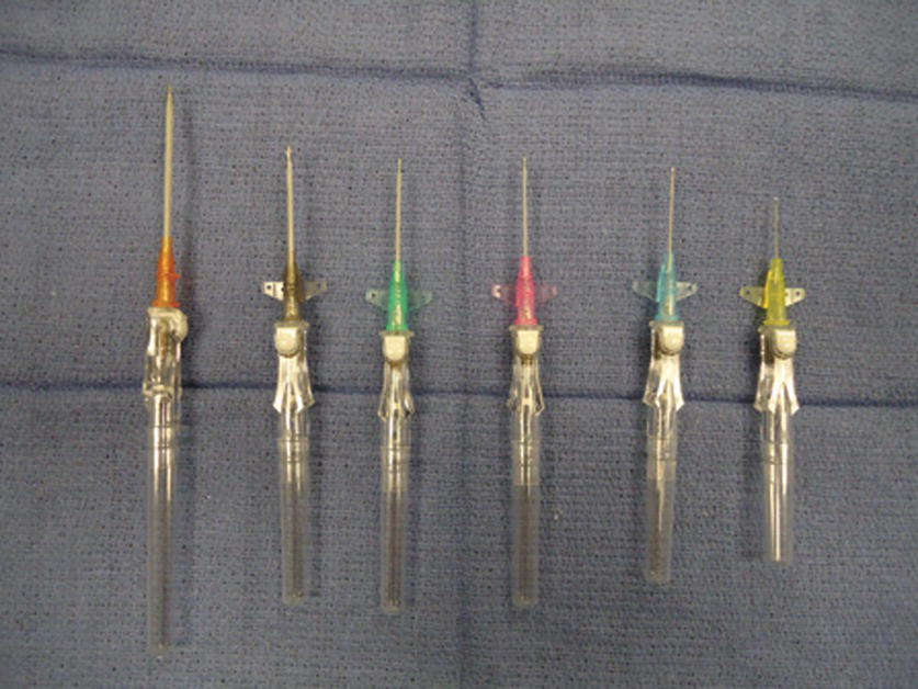
FIGURE 36.1. Peripheral intravenous catheters. Becton-Dickinson Insyte Autoguard catheter in different sizes. Left to right: 14G, 16G, 18G, 20G, 22G, and 24G.
The indication for the placement of PIV catheters include the following:
- Administration of fluids
- Administration of medications
- Blood transfusion
- Blood sampling for laboratory testing
Contraindications for PIV catheters depend upon the site where the IV line will be placed. Common contraindications include the following:
- Massive edema
- Burns or injury
- Insertion site distal to a potential vascular injury (i.e., access in lower extremities when the patient sustained abdominal or thoracic trauma)
- Local infection
- Existing arteriovenous fistula
- Previous radical axillary dissection (this is an older recommendation: many breast surgeons and anesthesiologists feel comfortable with IV access distal to a previous axillary dissection, especially if other sites are not readily available and if the patient has no lymphedema.)
PIV Catheter Equipment
All of the necessary materials and equipment should be available, prepared, and assembled at the bedside prior to placement (Fig. 36.2). Basic equipment includes the following:
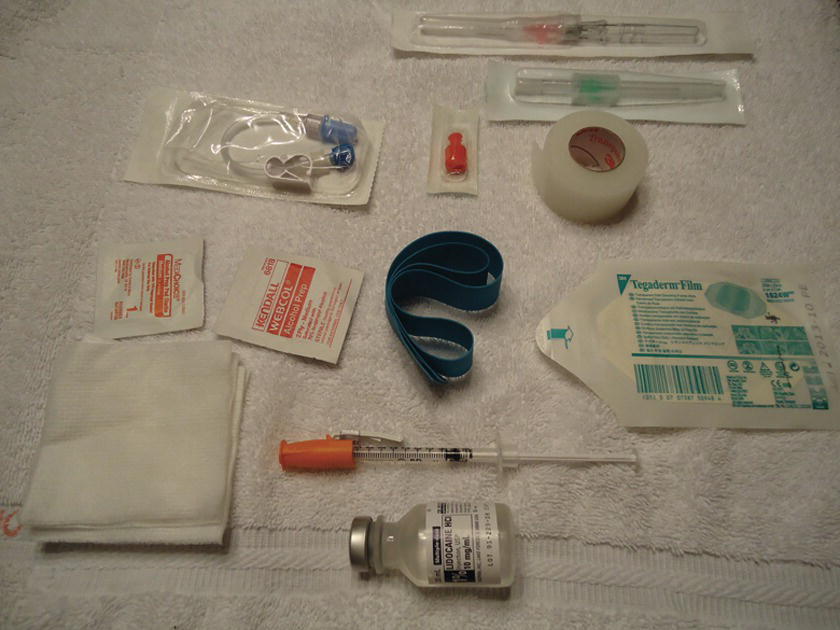
FIGURE 36.2. Setup for peripheral intravenous catheter placement.
- Appropriate size IV catheters (14-24G), at least two or three in each size. The full range of catheters should be available in the anesthesia cart; however, in most circumstances, it is not necessary to bring the full range of sizes to the bedside during a catheter insertion. The providers will have chosen a particular size they would like to insert. That size, and a couple of smaller catheters, should be ready at the bedside. The smaller catheters are ready in case the provider cannot locate a vein that can accommodate the desired size catheter. Two or three of each size of the appropriate catheters should be available in case more than one attempt at cannulation is necessary or a catheter is defective or inadvertently becomes unsterile.
- Nonlatex tourniquet.
- Alcohol or chlorhexidine swab.
- Sterile or nonsterile gauze.
- Transparent dressing.
- Adhesive tape.
- IV fluid bag with IV infusion set (flushed with fluid) or saline lock (short tubing flushed with saline and saline syringe). Note that there are different types of IV sets that are used for different purposes. See Associated Equipment section below for additional information.
- Three-milliliter syringe with a small needle (25G or 30G) and 1% lidocaine if local anesthesia at the insertion site is desired.
- In rare cases, an ultrasound or other device may be necessary to assist in peripheral vein location.
To prepare the IV infusion set, first, remove the protective cap on the IV fluid bag. Close the flow-regulating clamp on the infusion, set and insert the uncapped “spike” into the receptacle on the fluid bag. When “spiking” the bag, care should be taken that the spike on the infusion set remains sterile and does not touch anything other than the inner portion of the receptacle on the fluid bag. Once spiked, hold the fluid bag and drip chamber in an upright position and fill the drip chamber with fluid up to half of the chamber by squeezing the drip chamber a few times. The drip chamber performs two functions: it prevents air from entering the tubing and it permits the provider to see the flow of fluid into the tubing. Then, hang the bag on an IV pole and slowly open the regulating clamp to flush the entire tubing with fluid. While flushing, tap the tubing, stopcocks, and ports to remove small air bubbles trapped in these places. It is imperative to de-air the tubing when preparing the IV set for pediatric patients or adults with an intracardiac shunt (i.e., patent foramen ovale, atrial or ventricular septal defect) as even a small amount of air entering systemic circulation may cause an air embolism to vital organs.
Technique for Placing PIV Catheters
Choosing the site and appropriate superficial vein is the first and most important step in placing PIV catheters. Superficial veins in upper extremities are the first choice unless there are contraindications. Generally, the most distal peripheral sites are chosen as the first attempt. This allows the practitioner to move to a more proximal site if the initial attempt fails (cannulating a vein distal to a recent prior attempt in the same vein network can lead to fluid and medications leaking out of the hole directly above). In situations requiring large-bore IV access, such as trauma or cases in which the provider is anticipating significant blood loss, the median cubital vein is often preferred. These veins are usually large and stable. Unfortunately, infiltration (fluid or medications leaking out of the vein) can be harder to detect. In the circumstances where the veins of the upper extremities are not accessible, the saphenous vein of the lower leg or the veins of the lower leg and feet are the next choices. In difficult cases with poor peripheral venous access, the use of transillumination (i.e., AccuVein®, VeinViewer®) (Fig. 36.3A and B) or an ultrasound-guided technique may be necessary.

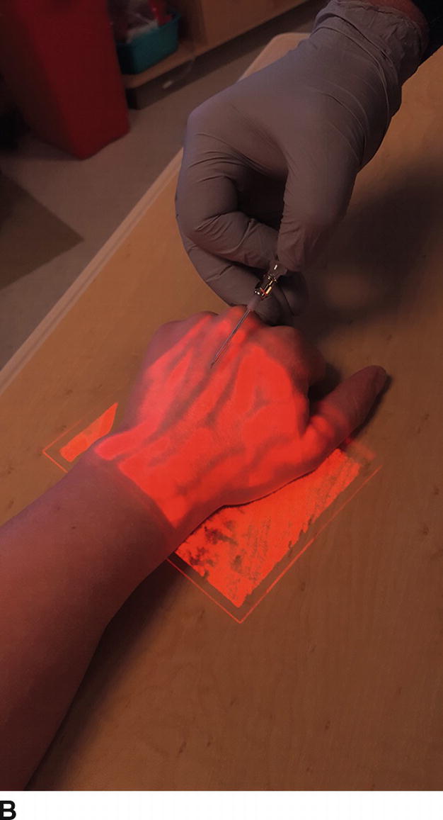
FIGURE 36.3. Panel A is a photograph of the transillumination AccuVein device; Panel B demonstrates the image that is obtained when the light from this device is applied to a patient’s hand, with the attenuation of color indicating a likely vein for cannulation.
As with any other invasive procedures, universal precautions should be applied in placing PIV catheters (see Chapter 23). Because infection rates from PIV catheters are very low, full sterile technique is not necessary; however, the site is still prepped with alcohol, and care is taken to maintain the sterility of the catheter and needle. Nonsterile gloves must be worn, and eye/face protection is recommended. A gown should be considered in special circumstances.
PIV Catheter Procedure
- Tightly apply a tourniquet to the extremity above the site (Fig. 36.4).
- Identify the vein by visualization and/or palpation.
- Cleanse the site with alcohol or chlorhexidine using an expanding circular motion.
- In awake patients, consider infiltrating local anesthesia (i.e., 1% lidocaine with a 27G or 30G needle) in the subcutaneous tissue at the insertion site, being careful not to enter the vein.
- Unpack the needle catheter and inspect for any defect.
- Insert the catheter (you will observe blood in the flow back in the needle hub chamber) and then advance the needle catheter a short distance into the vein (2-3 mm). Slide the catheter off the needle into the vein.
- Release the tourniquet and retract the stylet needle (any sharp material should be discarded in the appropriate sharp container, including safety needles). Blood in catheter hub should be observed (Fig. 36.5).
- Connect the IV set tubing or saline flush and ensure the correct placement of the IV catheter (observe free drip of fluid in the drip chamber or flush without resistance or signs of infiltration).
- Secure the catheter with a clear adhesive dressing (e.g., Tegaderm®). The clear dressing allows for future inspection of the insertion site (Fig. 36.6) (some practitioners prefer to place a piece of tape over the catheter hub before applying the adhesive dressing).
- Secure the IV tubing with tape over the skin. After applying the tape, check the security of the tubing, the connection to the catheter hub, and if fluid is infusing properly.
- Adjust the flow rate with a regulating clamp.
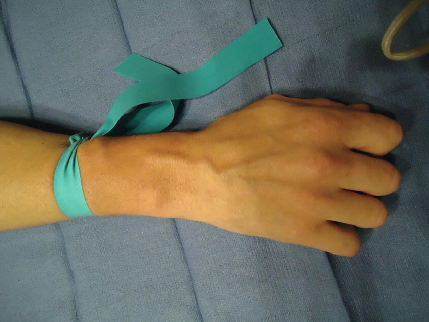
FIGURE 36.4 Peripheral intravenous catheter placement: Preparation. The tourniquet is placed proximal to the venipuncture site.

FIGURE 36.5 Peripheral intravenous catheter placement: Completing insertion. Once the catheter is in the vein, release the tourniquet. The blood in the hub of the catheter confirms that the catheter is in the correct position.
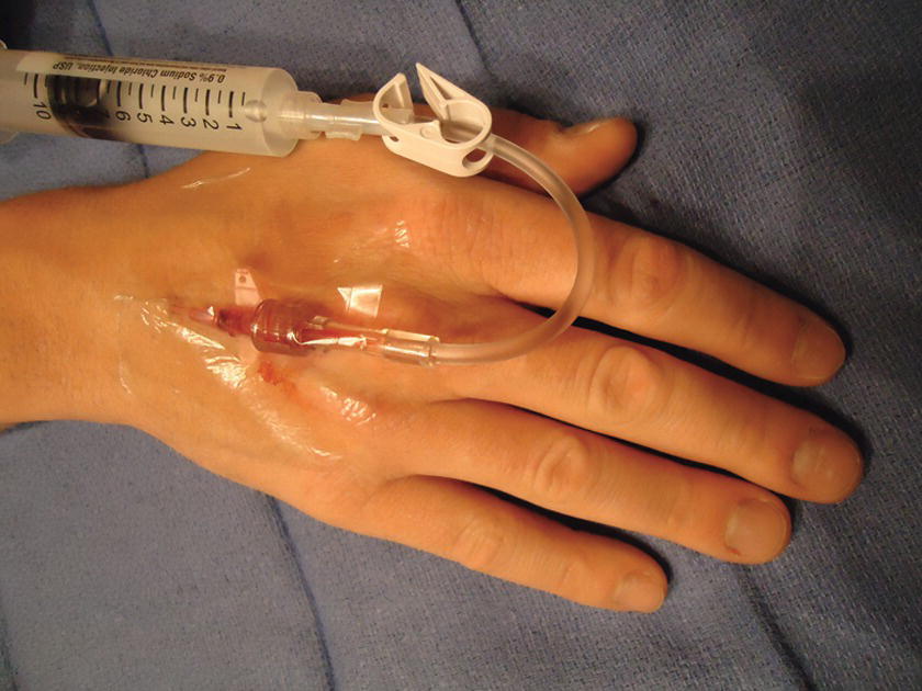
FIGURE 36.6 Peripheral intravenous catheter placement: Saline flush. The catheter is secure with Tegaderm, and the tubing is attached. The blood is now flushed with saline.
Removing PIV Catheters
When a PIV catheter is no longer required, it is malfunctioning (infiltrating or occluding), or any complication is identified, the catheter should be removed.
- Stop fluid infusion by occluding the regulating clamp.
- Remove the tape and Tegaderm.
- Place gauze over the IV site and remove the catheter while applying gentle pressure to the insertion site to stop any bleeding. You may need to apply pressure for 3-5 minutes until bleeding stops. Then, secure the gauze over the site with tape.
Complications of PIV Catheters
Complications related to PIV catheters include the following:
- Bleeding from the vein may result in bruises or a hematoma.
- Local infection at the insertion site.
- Phlebitis/thrombophlebitis: inflammation or clotting (thrombosis) of the vein.
- Infiltration: leakage of fluid or medication into the subcutaneous tissue. Depending on the pH and other properties of the fluid or medication that has infiltrated into the subcutaneous tissue, infiltration may cause inflammation or even tissue necrosis. If a large volume of fluid infiltrates, it may result in compartment syndrome (severe swelling in the extremity, causing compression of blood vessels and potentially cutting off the blood supply to the extremity or tissues).
Troubleshooting PIV Catheters
Regardless by whom and where PIV catheters are placed, monitoring for proper functioning and any signs of complications should be performed on a regular basis.
- Patient response: if the patient does not respond as expected to a medication administered through a PIV catheter, this may be the first sign that the IV is obstructed/kinked or has become disconnected or dislodged or is infiltrating (the medication is going into the subcutaneous tissue and not the vein).
- Inspect the IV bag to make sure that it is not empty.
- Inspect the insertion site for signs of infection or infiltration.
- Inspect the fluid flow rate by observing the drip chamber (flow rates are frequently adjusted during cases, and the provider may forget to return the flow rate to a desired level after making an adjustment). Also, checking that the IV fluid is flowing normally is reassuring that the IV line has not become disconnected or infiltrated.
- Check the drip chamber to make sure it is half full and air cannot get into the infusion tubing.
- It is also wise to keep IV lines labeled and untangled to prevent the injection of medications or infusions into the wrong IV. Administration ports should be readily accessible.
Central Venous Catheter
Definition and Indications
“Central lines” or central venous catheters (CVCs) are invasive catheters placed directly into the patient’s central venous circulation. There are a variety of locations, methods of placement, and types of catheters available for use depending on the clinical circumstance. The choice of location and type of line can have a dramatic impact on proper patient care. Prior to setup, confirm the desired line type and location with the placing provider.
Ideal placement of a central line leaves the catheter tip at a location in the superior vena cava, approximately 3-5 cm above the right atrium (RA), or at the cavoatrial junction. This is always confirmed by chest x-ray some time after insertion. This location allows administration of medications with negligible circulation times so as to speed their onset. Based on their presence in the central circulation, central lines are also a convenient location for blood sampling (discussed elsewhere in this chapter). With all blood returning to the heart via the inferior and superior vena cavae, the unique location of central lines also allows sampling of mixed venous blood for determination of SCVO2, or central venous oxygen saturation. While the uses of this laboratory value are beyond the scope of this chapter, it is important to be aware of this if assisting in blood sampling (see Chapter 10).
The most common site for placement of a central line remains the internal jugular vein (IJV) in the neck. From the right side of the neck, the cavoatrial junction lies at a depth of approximately 16-18 cm from the right and 19-21 cm from the left side of the neck of adults. This distance can vary by a few centimeters for adults who are very tall or very short. This difference between left and right is important to note as certain catheters may not have sufficient length for proper placement in the vein if using the left rather than the right side. Importantly, subclavian insertion locations affect the length of the catheter insertion similarly. Using a subclavian central line approach, the cavoatrial junction lies at a depth of approximately 13 cm from the right and approximately 16 cm from the left side of the chest wall (see below for proper placement location on the chest). A nice trick to estimate proper depth can be done by placing a catheter or a piece of string on the patient’s chest from the insertion site to approximately 2-3 cm below the sternomandibular junction and then measuring the length.
While it is possible to place these catheters using physical landmarks, the current standard of care is that internal jugular lines are to be placed using ultrasound guidance and that the internal jugular location is preferred to the subclavian when possible. The use of ultrasound in the placement of central lines has been found to decrease catheter-related complications and time of insertion in some studies.
Central Venous Anatomy
There are multiple locations for central line placement. This chapter provides brief anatomic descriptions of the three most common approaches.
Internal Jugular Vein Anatomy
The IJV is the primary draining vein from the head and leaves the skull at the level of the jugular foramen. It follows into the neck, entering the carotid sheath along with the common carotid artery, vagus nerve, and deep cervical lymphatics (Fig. 36.7). The vein traverses below and medial to the sternocleidomastoid (SCM) muscle, to enter the anatomic triangle bound by the two muscle bodies of the SCM and the clavicle (an important fact for placing central lines). The IJV then joins with the subclavian vein (SCV) to form the innominate vein near the medial edge of the anterior scalene muscle. The innominate vein then follows into the superior vena cava entering the heart.

FIGURE 36.7. Internal jugular vein anatomy. (From Moore KL, Dalley AF. Clinical Oriented Anatomy. 4th ed. Baltimore, MD: Lippincott Williams & Wilkins; 1999, with permission.)
Subclavian Vein Anatomy
Primarily draining the upper extremities, the SCV is a continuation of the axillary vein. Importantly, it is attached by fibrous tissue to the posterior aspect of the clavicle for approximately 3-4 cm. These attachments do not allow the vein to collapse even in severely hypovolemic patients, making this technique beneficial in such situations. After passing medial to the clavicle, the SCV joins the IJV to form the innominate vein at the level of the sternoclavicular junction, then passing into the heart as the superior vena cava (Fig. 36.8). It is important to note that the subclavian artery, brachial plexus, phrenic nerve, and internal mammary artery lie just posterior to different regions of the SCV and are separated by the anterior scalene muscle, making damage to these structures a potential complication. Just inferior to the SCV lie the pulmonary apex and pleura, creating a higher potential for pneumothorax with this technique.

FIGURE 36.8. Subclavian vein anatomy. (From Moore KL, Dalley AF. Clinical Oriented Anatomy. 7th ed. Baltimore, MD: Lippincott Williams & Wilkins; 2014, with permission.)
Femoral Vein Anatomy
The FV anatomy is quite simple, which makes accessing this vein easier than many others. As a continuation of the popliteal vein from the lower extremity, the FV enters the femoral sheath in the thigh and continues to the level of the inguinal ligament (Fig. 36.9). Passing underneath this ligament, the FV becomes the external iliac vein, which then travels along the psoas muscle to join with the contralateral external iliac vein, forming the inferior vena cava. The femoral approach takes place in the inguinal region at the level of the femoral sheath. It is important to note that the femoral artery and nerve lie just lateral to the FV in this region, allowing for potential damage to these structures with a femoral access technique. The term NAVeL is a useful mnemonic for remembering the relative femoral anatomy: from lateral to medial—Nerve, Artery, Vein, empty, Lymphatics (Fig. 36.9).
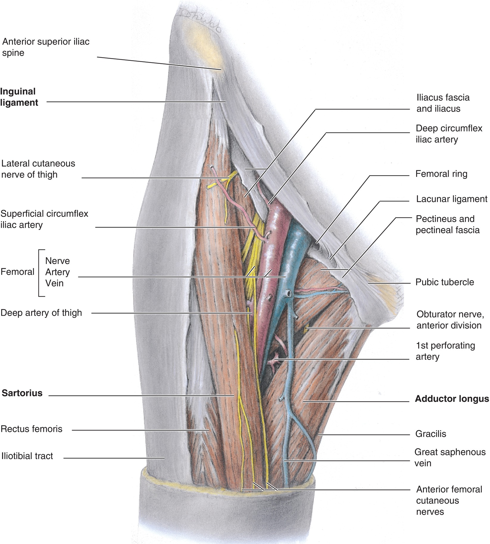
FIGURE 36.9. Deep femoral vein anatomy. (From Moore KL, Dalley AF. Clinical Oriented Anatomy. 4th ed. Baltimore, MD: Lippincott Williams & Wilkins; 1999, with permission.)
CVC Types
Triple-Lumen Catheter (Fig. 36.10)
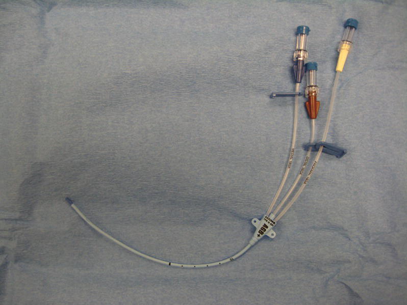
FIGURE 36.10. Triple-lumen central venous catheter.

CVC Introducer (Fig. 36.11)
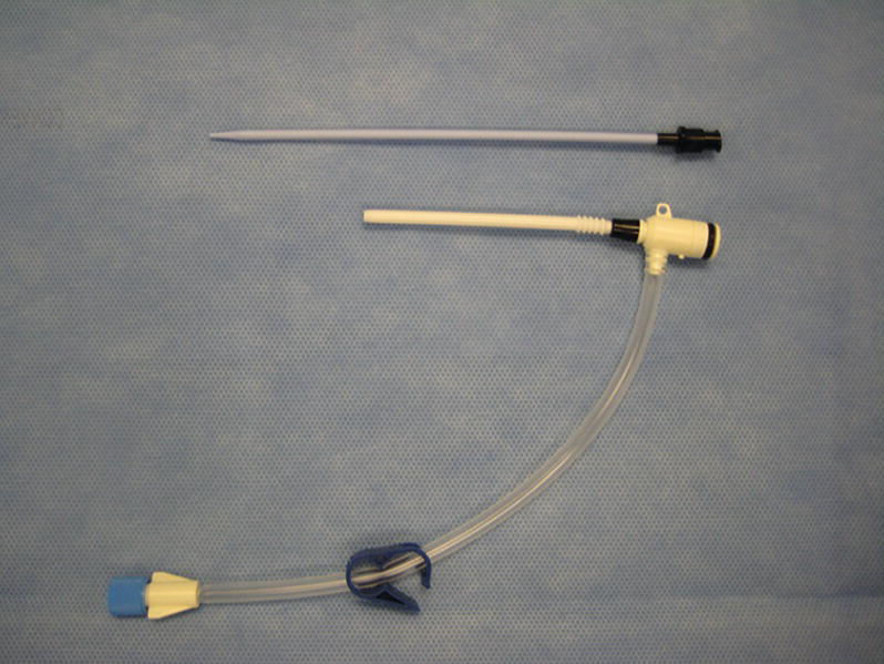
FIGURE 36.11. Sheath introducer.
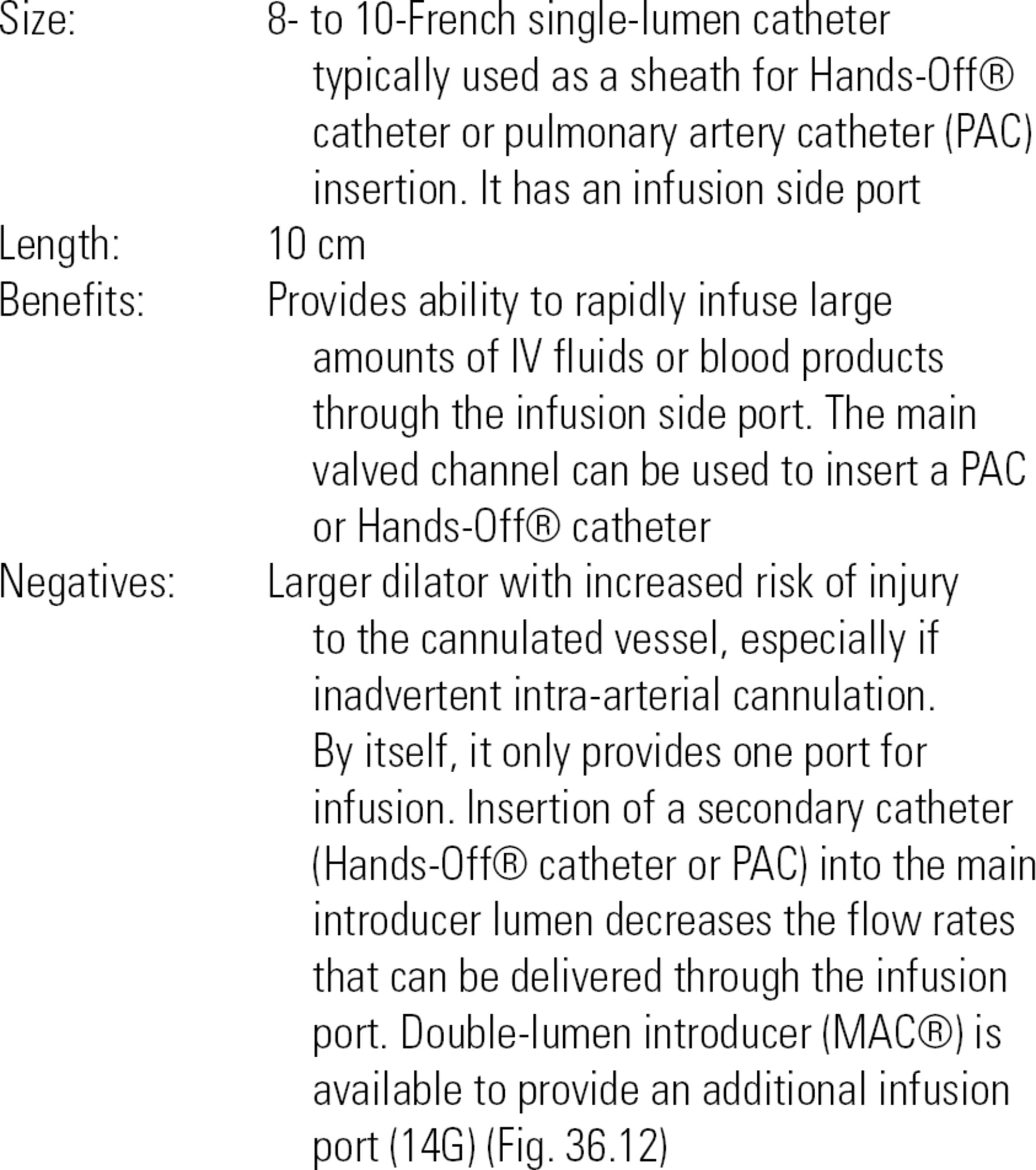
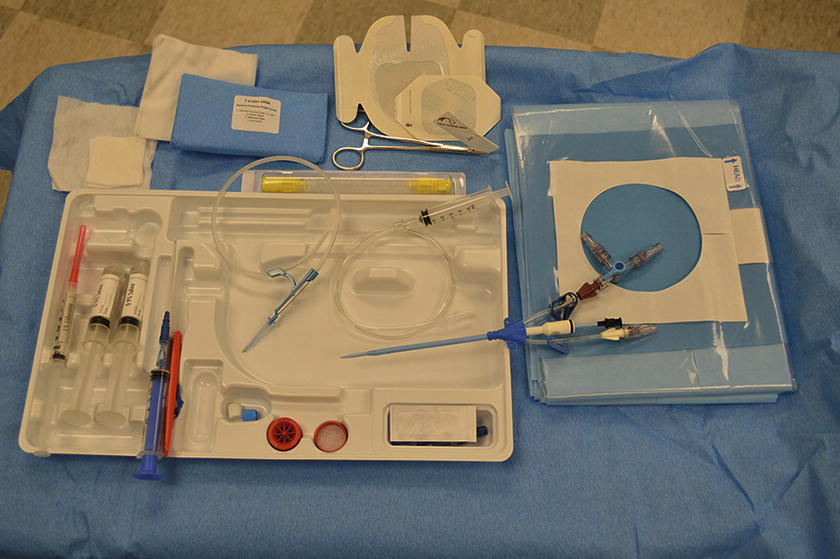
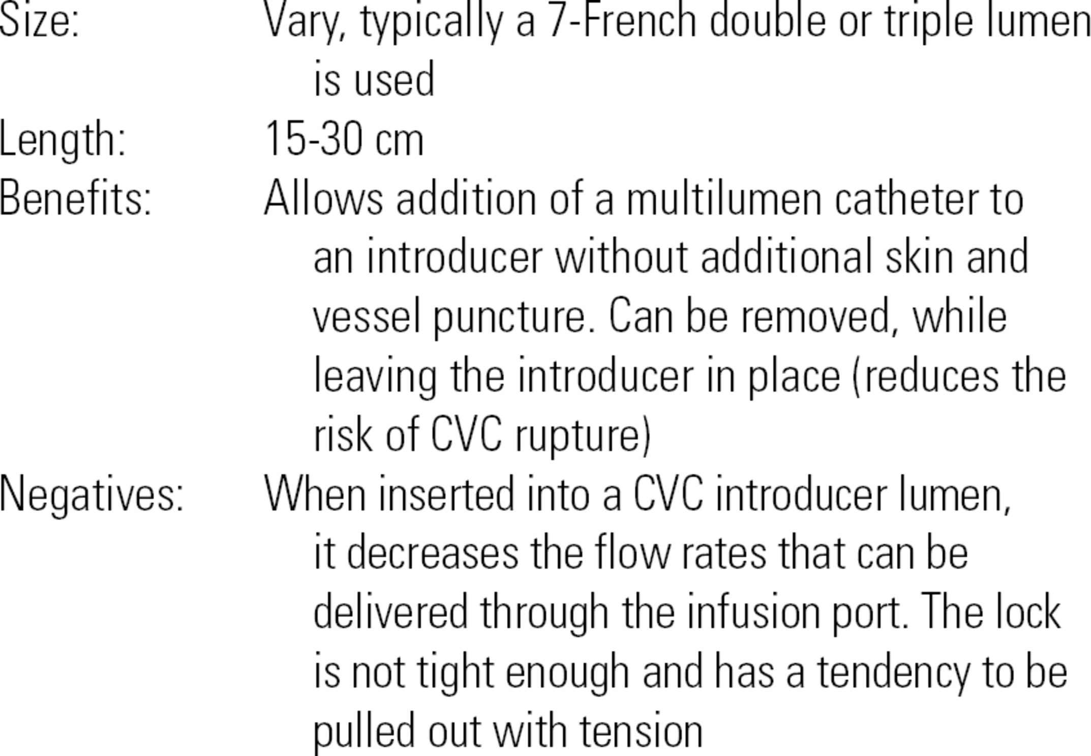
FIGURE 36.12. Double-lumen introducer.
Hands-Off® Catheter (Fig. 36.13)
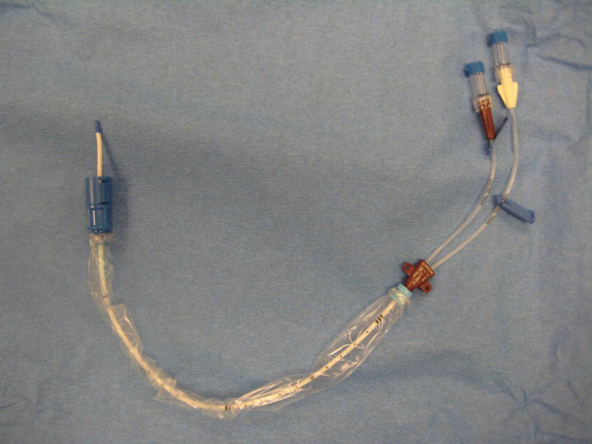
FIGURE 36.13. Double-lumen central venous catheter.
Single- or multilumen catheters are inserted through a CVC introducer and locked in place.
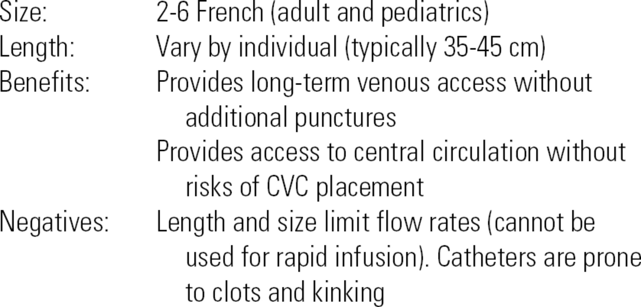
Peripherally Inserted Central Catheters
These are longer, thin catheters typically placed by IV therapy teams in the hospital when long-term IV access is required or the patient has difficult venous access. They can also be placed by interventional radiologists when unusually difficult. As the name implies, they are placed peripherally, typically in the antecubital, basilic, or cephalic veins. Patients may come to the operating room with peripherally inserted central catheters (PICC) lines in situ: they provide reliable central access at slow flow rates, must be handled under strict sterile conditions, and will have institutional or patient-specific flushing protocols before discharge to prevent clotting.
Tunneled CVC Ports
These are surgically placed, most often for infusion of chemotherapy and other caustic medications for long-term use. The infusion port is usually placed under the skin on the chest wall and can be accessed by placing a specialized needle called a Huber needle through the skin into the port under strict sterile conditions. It is critical that the port not become either infected or clotted during the access or deaccess process: only someone certified in your institution’s access protocol should access the port, an RN, an IV therapist, or an anesthesia provider.
CVC Indications
- Delivery of vasoactive medications
- Monitoring of intravascular volume
- Access for frequent blood draws
- Access for PAC
- Inability to obtain peripheral venous access
- Access for special CVC for potential aspiration of a venous gas embolus
- Access for insertion of cardiac pacemaker wires or catheters
- Access for long-term chemotherapy or parenteral nutrition
- Access for dialysis or plasmapheresis
- Infusion of medications that are irritating to peripheral veins
CVC Equipment
Much of the equipment required for central venous access is contained in specialized kits. Contents of CVC kits vary slightly according to the type of catheter included in the kit. In addition, many manufacturers allow larger institutions to customize the contents of the kits. A description of a generic kit is included below.
Generic CVC Kit (Fig. 36.14)
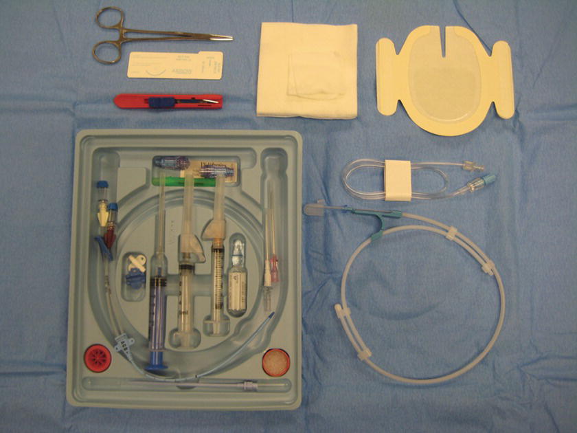
FIGURE 36.14. Central venous catheter insertion kit.
- CVC or CVC introducer
- 0.032-inch diameter threading wire (straight of J-tip), usually contained within a special sheath
- 7-French dilator
- Scalpel
- 18G thin-walled needle
- 22G “finder” needle
- 16G or 18G catheter-over needle
- 10- to 12-mL syringe (may be a special syringe that allows placement of the wire through the plunger)
- Suture (possibly straight or curved)
- Needle driver
- Caps for infusion port
- Gauze and sterile dressing material
- Manometry tubing (may or may not be included in kit)
- Large sterile drapes (may or may not be included in kit)
- Prep sticks and solution (may or may not be included in kit)
- Local anesthetic (1% lidocaine), 25G needle, and a 5-mL syringe (equipment for local anesthetic infiltration may or may not be included in the kit)
Additional equipment for CVC insertion that is usually not included in the kit:
- Linear array ultrasound with nonsterile ultrasound gel (nonsterile gel may be used for a “prescan” performed prior to the actual procedure). Sterile ultrasound gel is required for the actual procedure.
- Sterile gown, mask, gloves.
- Sterile towels and sterile gauze pads.
- Pressure transducer setup (if needed).
- Mobile table for setup of equipment.
- Sterile saline flushes.
- Sterile sleeve for the ultrasound probe.
- Sterile ultrasound gel.
- Additional sterile caps.
Technique for CVC Insertion
The first steps are to assemble and prepare the necessary equipment for CVC placement. These steps are described below:
- Position the patient in 15 degrees of Trendelenburg for SVC or IJV placement (increases the size of the veins). Confirm with the provider if and when the Trendelenburg position is desired. Some patients will not tolerate prolonged Trendelenburg position and may only need to be in this position from needle placement until the wire is out and the CVC lumen is capped. Other patients may not need Trendelenburg position if the IJV is dilated by heart failure.
- Turn on the ultrasound machine and place in position for easy viewing by provider.
- Place a mobile table on the side of the provider’s dominant hand for ease of access.
- In sterile fashion, open a central line kit, making sure not to touch the contents. Often, the providers will organize the contents of the kit how they prefer once it is opened. In other institutions, the anesthesia technician will don sterile gloves and organize the kit contents.
- Place two sterile saline flushes and sterile ultrasound sleeve and gel onto the sterile field.
- Some providers prefer to “prescan” the anatomy with the ultrasound before prepping the patient. If so, turn on the ultrasound, place a small strip of gel on the probe, and hand to provider.
- Once the “prescan” is finished, wipe gel off area and ensure that the region is clean and clear of any debris.
- If placing in the IJV, turn the patient’s head slightly to the contralateral side (Fig. 36.15). It may also be necessary to remove the patient’s pillow if it is tilting the patient’s head too far forward or is in the way of the neck. If the patient is intubated, the circuit tubing should be moved so that it is out of the way and secure. In all of these steps, care should be taken to avoid dislodging the endotracheal tube.
- Using sterile technique, prep the region for at least 30 seconds. For IJV: prep from bottom of the ear to the clavicle and from the trachea to as far lateral as possible (Fig. 36.16). For SCV: prep from 1 to 2 inches above the clavicle to just above the nipple and from the anterior shoulder to the sternum. For FV: prep from just below the hip to approximately 6 inches below the inguinal crease and from medial groin to the lateral thigh.
- Assist the provider with gowning and gloving. Tie the gown in the back. Do not touch the provider’s arms, hands, or chest. Make sure the provider is wearing a mask and loose ties are not hanging down.
- Assist with draping, ensuring to only touch the underside of the drape when it is passed to you. Gently pull the drape until completely opened and the body covered (Fig. 36.17).
- When the provider is ready, place a small strip of nonsterile ultrasound gel on the probe. The provider will place his or her hand into the sterile sleeve and will grab the probe from you. As he or she passes the end of the sleeve to you, grab the very end and pull along the length of the cable, making sure no uncovered portion of the cable touches the sterile field (Fig. 36.18). Refer to Chapter 41 for the details on the operation of the ultrasound machine and transducer. The provider may ask for color Doppler during the procedure to confirm the location of vascular structures.
- See below regarding the specifics of cannulating the vein and placing the catheter.
- Once the vein has been entered and the guidewire is in place, the provider may ask you to take a picture with the ultrasound machine, showing the wire inside the vessel (Fig. 36.19). In many institutions, the picture is printed and placed in the patient’s chart. Ask the provider if a picture will be required and what to do with the print. In some institutions, the provider will want a personal copy of the print for anesthesia billing.
- During insertion, the providers’ attention may be focused on the line placement itself. Periodically, review the patient’s status on the monitors and notify the provider of any significant changes in blood pressure, oxygen saturation, machine alarms, heart rhythms, etc.
- After the procedure is completed, carefully remove the drapes, making sure not to pull the line out and to avoid extubating the patient.
- Connect the CVP transducer tubing to one of the flushed ports on the central line (preferably one of the 18G lumens), open all stopcocks, and zero the CVP transducer. Review the waveform and pressure reading (Fig. 36.20).
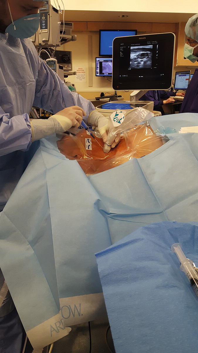
FIGURE 36.15. Internal jugular vein puncture. (From Moore KL, Dalley AF. Clinical Oriented Anatomy. 7th ed. Baltimore, MD: Lippincott Williams & Wilkins; 2014, with permission.)
FIGURE 36.16. Preparation of internal jugular vein: the skin is prepped with tinted chlorhexidine swab from just below the right ear and chin to the right nipple crossing the midline.
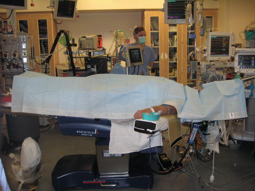
FIGURE 36.17. Full-body drape. Patient’s entire body should be covered with a drape.
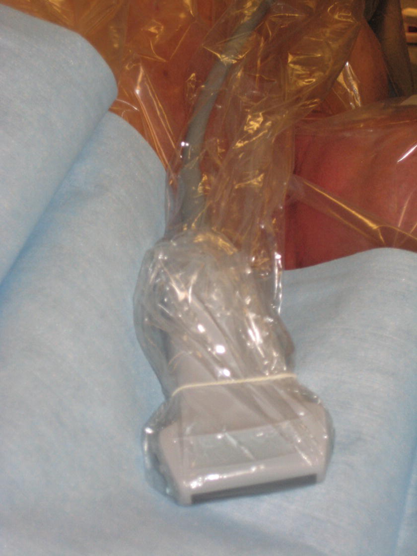
FIGURE 36.18. Ultrasound transducer is covered in sterile sheath for use in the sterile field.
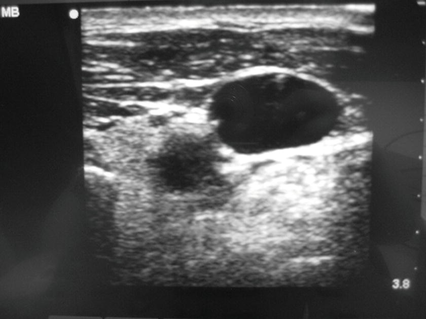
FIGURE 36.19. This photograph is the still shot of the ultrasound machine screen that demonstrated the presence of the wire in the internal jugular vein. The photograph is taken and placed in patient’s chart for the documentation. This is required for the billing of ultrasound-guided central venous catheterization.
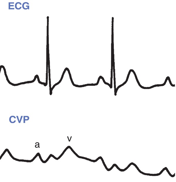
FIGURE 36.20. Central venous pressure normal waveform. CVP, central venous pressure; ECG, electrocardiogram. (From Springhouse. Lippincott’s Visual Encyclopedia of Clinical Skills. 1st ed. Philadelphia, PA: Wolters Kluwer Health; 2009, with permission.)
Provider Technique for Placing a CVC
The details of the placement of the central line are intended to give the anesthesia technician a basic understanding of the procedure. This information will help you to be able to assist the provider as needed, particularly if in your institution, the anesthesia technician gowns and gloves and actively hands in sterile equipment to the provider.
After the setup above is completed and all ports of the CVC are flushed with saline, the provider will identify the vein with the ultrasound probe with a sterile cover in one hand and a needle/syringe in the other hand. Details change depending upon slight variations in technique. Here, we describe the Seldinger technique (the catheter-over needle technique) using an 18G catheter and needle (if the kit does not contain an 18G catheter over a needle, a regular 2-inch 18G PIV catheter may be opened using sterile technique and placed on the provider’s tray). The needle is advanced with constant negative pressure in the syringe by slightly pulling on the plunger. The provider will monitor the advancement of the needle on the ultrasound monitor. Once a flash of blood is noted in the syringe, the angle of the needle is to be changed to a shallower angle and the catheter is threaded into the vessel (if the provider is using only the thin-wall needle without the catheter, this step will be skipped and the provider will proceed directly to passing the guidewire into the vein through the needle). The needle is removed, covering the end of the catheter with a finger (patients who are breathing spontaneously create negative intrathoracic pressure during inspiration and can entrain air into the circulation through an open catheter or needle). If using manometry, the tubing is connected to the catheter hub and lowered below the head to fill with blood. This tubing is then raised above the head, to confirm that the blood column falls slowly and that the pressure in the tubing is consistent with venous pressure (if the artery is accidentally cannulated, the pressure in the tubing will be much higher). Some providers ask to have the manometry tubing connected to a transducer to measure the pressure. The manometry tubing is removed, and the wire is advanced into the catheter (and vein) to approximately 15-20 cm, and the catheter is removed over the wire. A still picture showing the wire in vein (Fig. 36.19) may be obtained and printed for the record at this time. A small skin nick is made with the scalpel to make room for the CVC. The dilator is advanced over the wire to open a path for the CVC through the skin and deeper tissues. The dilator is removed over the wire. The CVC is fed over the wire until it almost reaches the skin. In most cases, the wire will need to be pulled back and fed back into the CVC until it emerges from the most distal port. Holding the far end of the wire (to avoid losing a wire into the central circulation), the central line is then advanced all the way over the wire and into the vein. The wire is then removed. Each port is flushed with sterile saline once ability to draw back blood is confirmed (many institutions preflush the catheter ports before the catheter is inserted). The ports are capped, the line is sutured in place, and the site is covered with a clear sterile dressing.
Complications
Potential complications of CVC insertion include the following:
- Hemorrhage.
- Damage to pleura, pneumothorax.
- Arterial damage or arterial cannulation.
- Thrombosis.
- Arrhythmias: the wire can be advanced into the heart and cause an arrhythmia, particularly if it is advanced into the ventricle. A few premature ventricular beats are not uncommon. The wire should be withdrawn until the abnormal beats subside. On occasion, medications or further treatment will be necessary if the arrhythmia is serious (e.g., ventricular tachycardia).
- Retained wire.
- Nerve damage.
- Vascular erosion with bleeding into the chest.
- Cardiac tamponade and wall rupture.
- Phlebitis.
- Infection: local site infection or bloodstream infection.
Troubleshooting
Most common problems encountered with central lines will be managed by the provider; however, a few common problems and possible solutions are shown in Table 36.1.
Table 36.1. Troubleshooting for Central Venous Catheters

Intraosseous Venous Access
Definition and Indications
The intraosseous route is one of the quickest ways to establish access for fluid infusion, administration of medications, or blood transfusions in an emergency situation, such as pediatric resuscitation. The bone marrow cavity is in continuity with the venous circulation; therefore, it can be used to administer medication, fluid, and blood. Intraosseous access can be obtained in the proximal tibia, the distal tibia, the proximal humerus, the femur, the iliac crest, or even the sternum. Intraosseous access sites can be used for blood samples for laboratory tests and cross match. Intraosseous access is indicated when emergent vascular access is required but peripheral or central access cannot be obtained or cannot be obtained in a timely fashion (i.e., life-threatening situation, pediatric emergency). It is not the first choice for access, but after attempts to obtain vascular access fail, and time is limited, it can be a lifesaving and efficient alternative. Intraosseous access takes less than 2 minutes to obtain.
Contraindications include fractured bones, bones with osteomyelitis, and proximal bone fracture (i.e., do not use tibia if ipsilateral femur fracture is present).
Intraosseous Access Equipment
- Alcohol or chlorhexidine swab.
- Local anesthetics (1% lidocaine).
- 5-mL syringe.
- 50-mL syringe.
- Intraosseous infusion needle (i.e., Dickmann IO needle®, needle sizes: 14G, 16G, and 18G). Smaller sizes are used for infants (Fig. 36.21).
- Specialized intraosseous access tools (e.g., FAST1 and EZ-IO) (Figs. 36.22 and 36.23) are available, which may include special devices or handheld battery-operated drills to drive the needle system through the bone and into the intraosseous space.
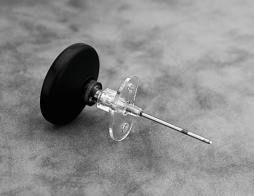
FIGURE 36.21. Intraosseous infusion needle with Dieckmann modification and standard hub design (Cook Medical). (From Tobias JD, Ross AK. Intraosseous infusions: a review for the anesthesiologist with a focus on pediatric use. Anesth Analg. 2010;110(2):391-401 with permission.)
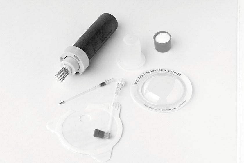
FIGURE 36.22. First Access® for Shock and Trauma (FAST1®) device (PYNG Medical). (From Tobias JD, Ross AK. Intraosseous infusions: a review for the anesthesiologist with a focus on pediatric use. Anesth Analg. 2010;110(2):391-401, with permission.)

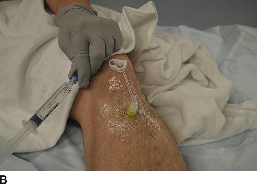
FIGURE 36-23 A: With permission from Tobias JD, Ross AK. Intraosseous infusions: a review for the anesthesiologist with a focus on pediatric use. Anesth Analg. 2010;110(2):391–401. EZ-IO® driver with cover. The black cover prevents accidental trigger presses that can drain the battery. B: IO line placed in the tibia.
Technique
1. Determine the site. The anteromedial aspect of the tibia is most commonly used as it lies just under the skin and can be easily identified.
2. Palpate the tibial tuberosity. The anteromedial tibial insertion site will be 1-3 cm below and 2 cm medial to the tuberosity.
3. Wear sterile gloves and clean and then prep the skin by using an outward circular motion.
4. In awake patients, inject local anesthetic in the skin and continue to infiltrate until the periosteum (hard surface) is encountered.
5. Position the lower extremity as flexing the knee and placing a pillow or sandbag behind the knee for support. If not available, have an assistant stabilize the lower leg by holding the knee and ankle from the other side.
6. Hold the limb just above the insertion site and insert the intraosseous needle perpendicular to the skin and slightly caudal (toward toes) to avoid injury to the epiphyseal growth plate.
7. Advance the needle with a drilling motion (or with the drill) until loss of resistance is felt when the needle penetrates the cortex of the bone and enters the marrow cavity. This may not be obvious in younger children.
8. Remove the stylet and connect the 5-mL syringe. Confirm the correct position by aspirating blood. Inject 10 mL of saline to check for any signs of infiltration (swelling of limb or increase in resistance). In awake patients, inject 3-5 mL of preservative-free 1% lidocaine into the intraosseous space. The injection should be performed slowly to avoid patient discomfort. If not successful, remove the needle and try another site.
9. Secure the needle in place with a clear dressing, sterile gauze, and tape.
Intraosseous Complications
This is a relatively simple procedure, but there is the possibility of serious complications including:
- Tibial fracture
- Extravasation
- Compartment syndrome
- Osteomyelitis
- Skin necrosis
- Microscopic pulmonary fat and marrow embolism (not clinically significant)
The intraosseous needle should be removed as soon as peripheral or central vascular access is obtained, or within 24 hours, to minimize the risk of complications.
Associated Equipment
Basic IV Sets
A basic IV setup consists of a bag of IV fluid; an IV infusion set that has a spike, a drip chamber, a tube, a regulating clamp, and injection ports; one or two three-way stopcocks; and an extension tube. Some of the sets are preassembled (Fig. 36.24); however, be sure to tighten and secure all connections before clinical use. Additional IV setups include the following:

FIGURE 36.24. Regular intravenous set. This shows a preassembled regular IV set with a macrodrip chamber, a clamp, double stopcocks, and an extension tubing.
- Microdrip (Fig. 36.25): The regular IV set (macrodrip) has a drip chamber that delivers 10, 12, or 15 drops equal to 1 mL. The microdrip IV set has a drip chamber that delivers 60 drops equal to 1 mL. Microdrip IV sets are used when small amounts and more exact fluid or drug administration are required (e.g., pediatrics or critical care settings). Because 1 hour is 60 minutes, the number of drops in 1 minute represents the milliliters delivered in 1 hour (100 drops in 1 minute is equal to 100 mL/h).
- Buretrol® (Fig. 36.26): It is an in-line receptacle between the IV set and the IV fluid bag that has a maximum volume of 150 mL. It is a safety mechanism to avoid the overadministration of fluid to small patients (<15 kg). A defined amount of fluid is filled in the Buretrol® from the IV bag and then connecting tube to the bag is clamped off. Even with an IV pump malfunction, only the amount in the Buretrol® would be administered to the patient.
- Basic blood tubing: The infusion set for blood transfusion is equipped with a 200-μm filter in the drip chamber. Some blood transfusion sets used intraoperatively also have a manual pressure pump for rapid infusion.
- Y tubing (Fig. 36.27): It is used as the IV line when blood transfusion is anticipated. One side of Y tubing is spiked to normal saline and used to flush the tubing. When blood transfusion is needed, spike the blood bag with the other side of Y tubing to start blood transfusion.
- Setups for infusions pumps (Fig. 36.28): Infusion pumps require specific tubing that fit certain pumps. Generally, it consists of a drip chamber, a regular tubing, a clamp, and the elastic tubing that lies inside of the pump.

FIGURE 36.25. Microdrip (left) and macrodrip (right) IV sets.

FIGURE 36.26. A preassembled intravenous set with a Buretrol®.

FIGURE 36.27. Y-tubing blood transfusion set.
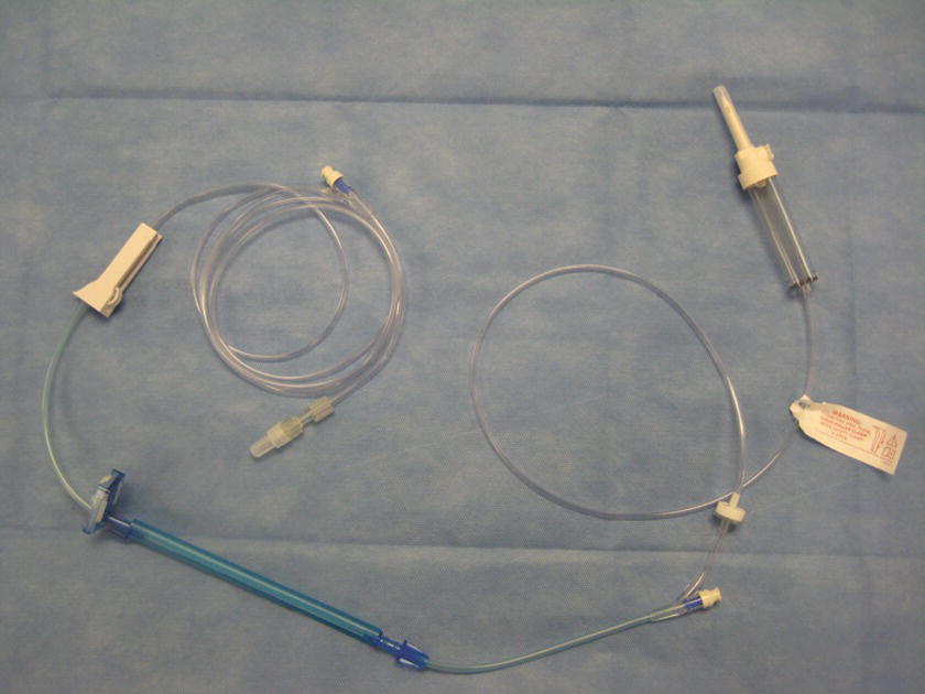
FIGURE 36.28. Infusion pump set.
All IV sets should be primed prior to use to avoid injecting air into the patient. To flush the entire set with fluid, close the regulating clamp first and then spike the IV bag. Fill the drip chamber up to half of the capacity by squeezing and releasing the chamber. Then, open the clamp to flush the tubing until all air and bubbles have been removed from the tubing. The stopcocks and injection ports tend to trap the air. Tap these places with a finger or a surgical clamp to release bubbles. Once all air has been removed, close the clamp. De-airing is particularly important in pediatric setup and adult with intracardiac shunts. Label the set with the date and the time as it should be used as soon as possible based on the institutional policy. Do not write on the fluid bags directly with markers.
Fluid Warmer
Patients undergoing general anesthesia for operative procedures become hypothermic due to multiple reasons (i.e., lack of muscle activity, vasodilatation, hypothalamic depression, radiation, conduction, evaporation, convection of body heat) (see Chapter 33, Temperature Management). Administration of continuously warmed fluid has been shown to decrease the incidence of intraoperative hypothermia. Different types of fluid/blood warmers are available on the current market; however, they share several common characteristics. Most consist of a warming device and a disposal tubing component (e.g., Hotline®, Level1®) (Figs. 36.29 and 36.30). The IV tubing is connected to the proximal connector of the disposable warming tubing. The distal end of the warming tubing is connected to IV tubing, which is connected to the patient. They function by circulating warm sterile water through the outer lumen of the warming tubing, which surrounds an inner lumen through which the IV fluid flows. The Bair Hugger® warming system uses a special coil of tubing that can be attached to the hose of the forced-air warming units. Another system is the Ranger® fluid warming system that uses a proprietary cassette and highly conductive heating plates. All of these systems require special disposable components and wall socket power. Thermal Angel® is a disposable, in-line, battery-powered warming device. Its major advantage is that it can be used during transport of critically ill patients.
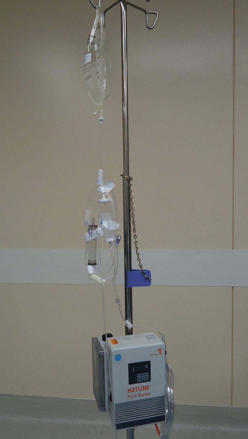
FIGURE 36.29. Hotline®. (Courtesy of Smiths Medical.)

FIGURE 36.30. Level1®. (Courtesy of Smiths Medical.)
Although it is very rare, there is a case report of a superficial burn caused by Hotline® tubing touching the patient’s skin over a long period of time. Caution must be taken to prevent this type of complication. Setting up and troubleshooting vary in different brands and require in-service training by the manufacturer or distributor and referring to the manufacturer-specific manuals. However, the basic setup is very simple. After installing a prefilled tubing, coil, or cassette in the warming unit, simply turn the device on.
Rapid Infusion Systems
Rapid infusion systems are commonly used intraoperatively to transfuse massive amounts of fluids and of blood components rapidly (see also Chapter 62, Massive Hemorrhage). Some of the devices use pressure (e.g., Level1®) (Fig. 36.30), and others use rotary pumps (e.g., Belmont®) (Fig. 36.31). Both systems are equipped with filters, line pressure monitors, air detectors, and a warming device with temperature monitors. In addition, the Belmont® system has a reservoir and a computer system to regulate flow rate. Both systems should not be used to transfuse platelets, cryoprecipitate, or granulocyte suspensions. They should not be used where rapid infusion is medically contraindicated.

FIGURE 36.31. Belmont® rapid infuser system. (Photo courtesy of Belmont Instrument Corporation.)
Administration of blood (red cells) under pressure may cause hemolysis, resulting in hyperkalemia and hemoglobinemia. Continuous supervision by trained personnel is required in the use of these devices. General setting up is described below; however, it is essential to follow the manufacturer’s instruction for setup, operation, and troubleshooting (Fig. 36.32).
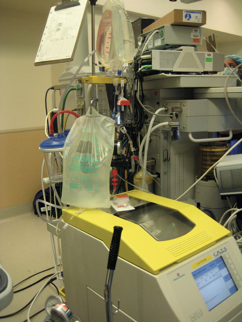
FIGURE 36.32. Autotransfusion system.
1. Inspect the system.
2. Install the disposable set (including a reservoir for Belmont®).
3. Turn the power on.
4. Spike the saline bag and prime the tubing (and fill the reservoir in Belmont®).
5. Connect extension tubing to the patient’s IV access and start infusing.
Autotransfusion
As a part of the effort to decrease the need for allogenic blood transfusion, intraoperative blood salvage and autologous blood transfusion (autotransfusion) have been employed in surgeries since the early 19th century. See Chapter 44 for further information about autotransfusion.
Summary
Obtaining vascular access, including inserting CVCs, is an extremely common procedure in anesthesia. In addition, the anesthesia provider may request a fluid warmer, rapid transfuser, or cell saver. The anesthesia technician will be frequently called upon to assist the anesthesia provider in obtaining and setting up equipment for these procedures, and the technician should be thoroughly familiar with the equipment. In addition, the technician should be familiar with sterile technique, different infusion sets, and pressure transducers. The anesthesia technician should also be prepared to troubleshoot a wide variety of equipment utilized for these procedures. Errors during equipment preparation or operation can have disastrous consequences, including air emboli in the arterial circulation, thrombosed or infiltrated catheters, or central bloodstream infections.
Review Questions
1. The rate of fluid flow in a catheter INCREASES with
A) The fourth power of the increased radius of the catheter lumen
B) Higher pressure applied to the fluid line (e.g., a pressurized IV bag)
C) Increasing length of the catheter
D) A and B
E) All of the above
Answer: D
The radius of the catheter is a critical determinant of fluid flow rates and is related to the fourth power of the radius. Increasing the catheter length would decrease the fluid flow rates.
2. In French sizes, the larger the number is, the larger the diameter is.
A) True
B) False
Answer: A
In French sizes, the larger the number, the larger the catheter. This is in contrast to the Stubbs wire gauge system in which the larger the gauge, the smaller the catheter.
3. A rapid infuser system is NOT equipped with
A) Filter
B) Heat exchanger
C) Roller pump
D) Reservoir
E) Centrifuge
Answer: E
The rapid infuser system is equipped with filters, line pressure monitors, air detectors, and a warming device with temperature monitors. In addition, the Belmont® system has a reservoir and a computer system to regulate flow rate. The centrifuge is one of the features of an autotransfusion system (Cell Saver®).
4. Which infusion set should be used to maintain strict control over the volume of fluid or medication delivered?
A) Buretrol®
B) Microdrip
C) Infusion pump tubing with an infusion pump
D) Y-type blood administration tubing
E) A, B, and C
Answer: E
A Buretrol® is a 150-mL chamber that can be used to control medication or volume delivery, particularly in pediatric patients. A microdrip set has smaller drops (approximately 60 drops per milliliter) and can be used to deliver lower infusion rates. An infusion pump can be set to control infusion amounts and rates. A Y-type blood administration set would be used to deliver higher volumes of fluid or blood.
5. Which of the following statements are TRUE with regard to central venous access?
A) The internal jugular, subclavian, and femoral veins can be used for peripheral venous access.
B) It is necessary to gown when inserting a CVC.
C) Manometry is used to verify the CVC is not in the lung.
D) A cordis introducer CVC should be used if you do not expect large amounts of blood loss.
E) All of the above are TRUE.
Answer: B
It is necessary to use a sterile gown and gloves and use a mask when inserting a CVC to reduce the incidence of bloodstream infections. The internal jugular, subclavian, and femoral veins are used for central venous access. Once a CVC has been inserted, measuring the pressure in the line can help determine that the line was placed in a vein (low pressure) and not inadvertently in an artery (high pressure). A cordis introducer has a very large infusion channel (if nothing else is put into it, e.g., hands-free catheter or PAC) and can be used for high-flow infusions.
6. Which of the following should be available to place a CVC?
A) Ultrasound machine
B) CVC kit
C) Infusion setup
D) IV fluids
E) All of the above
Answer: E
All of the above should be available for CVC insertion. Ultrasound is extremely common to identify the relevant anatomy and guide needle insertion into the vein.
7. Which of the following statements are TRUE with regard to peripheral venous access?
A) A tourniquet should never be used.
B) A transducer should be set up.
C) Ultrasound can be used to identify the vein.
D) The FV can be used.
E) All of the above are TRUE.
Answer: C
In rare circumstances, a peripheral vein can be difficult to see or palpate. In these cases, ultrasound can be utilized to identify a vein. A tourniquet is almost always used to enlarge the vein so that it can be more easily palpated and cannulated. A transducer is used to monitor CVP and is not used for peripheral venous lines. The FV is part of the central circulation and is not considered a peripheral vein.
8. Which of the following is NOT an appropriate location of intraosseous access?
A) Distal radius.
B) Proximal humerus.
C) Sternum.
D) Iliac crest.
E) All of the above are appropriate location for IO access.
Answer: E
Intraosseous access can be obtained in the proximal tibia, the distal tibia, the proximal humerus, the femur, the distal radium, the iliac crest, or sternum.
9. Which of the following is NOT TRUE regarding intraosseous access?
A) Intraosseous access site can be used for blood samples for the laboratory tests and cross match.
B) Contraindications include fractured bones, bones with osteomyelitis, proximal bone fracture, previous sternotomy, and some rare disorders of bone development.
C) All of the IV mediation and blood products can be administered through the intraosseous access, and the onset of action and peak drug level are comparable to those of IV administration.
D) The intraosseous needle can be maintained more than 24 hours without increasing the risk of complications.
E) All of the above are TRUE statement.
Answer: D
The intraosseous needle should be removed as soon as peripheral or central vascular access is obtained, or within 24 hours, to minimized the risk of complications.
SUGGESTED READINGS
Atalay H, Erbay H, Tomatir E, et al. The use of transillumination for peripheral venous access in paediatric anaesthesia. Eur J Anaesthesiol. 2005;22:312-323.
Donner M, Schonfeld W. Monitoring. In: Pino RM, Albrecht MA, Bittner EA, et al., eds. Clinical Anesthesia Procedures of the Massachusetts General Hospital. 9th ed. Philadelphia, PA: Wolters Kluwer; 2016:133-151.
Hasselberg D, Ivarsson B, Anderson R, et al. The handling of peripheral venous catheters—from non-compliance to evidence-based needs. J Clin Nurs. 2010;19: 3358-3361.
Hignett R, Stephens R. Radial arterial lines: practical procedures. Br J Hosp Med. 2006;67(5):M86-M88.
Josephson DL. Intravenous Infusion Therapy for Nurses: Principle & Practice. 2nd ed. Clifton Park, NY: Delmar Learning; 2004.
Tobias JD, Ross AK. Intraosseous infusions: a review for the anesthesiologist with a focus on pediatric use. Anesth Analg. 2010;110(2):391-401.