5.4. NR and LTE-M coexistence
3GPP Release 15 introduces a NR-access technology known as New Radio (NR), which offers significant performance advantages over LTE in terms of data rates, latency, deployment flexibility and energy efficiency (see Chapter 2.4 for an introduction of NR and Reference [27] for detailed description of NR). NR is designed for enhancing the performance of mobile broadband and ultra-reliable low-latency communications (URLLC) services (described in Chapter 11), whereas low-power wide-area (LPWA) IoT use cases are expected to already be adequately addressed by existing 3GPP technologies such as LTE-M and NB-IoT. It has been shown that LTE-M and NB-IoT fulfill the 5G massive MTC requirements (see performance evaluations in Chapters 6 and 8, respectively) and thus qualify as 5G component technologies. Therefore, it is desired that LTE-M and NB-IoT can coexist efficiently with NR also after a potential migration from LTE to NR. NR coexistence with LTE-M is covered in this section, and NR coexistence with NB-IoT is covered in Section 7.4.
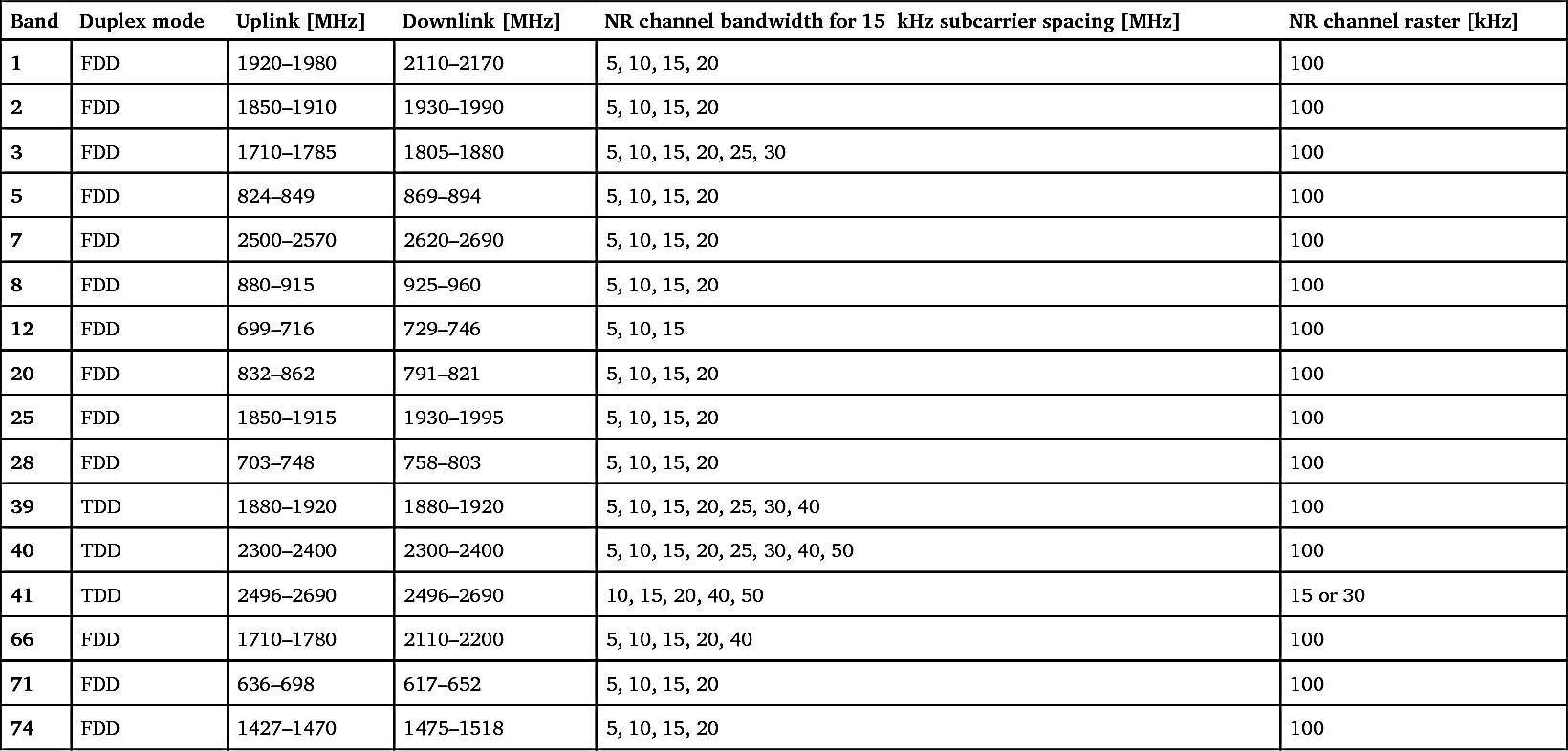
LTE-M is defined in LTE bands 1, 2, 3, 4, 5, 7, 8, 11, 12, 13, 14, 18, 19, 20, 21, 25, 26, 27, 28, 31, 39, 40, 41, 66, 71, 72, 73, 74 and 85 (see Table 5.3 for the frequency ranges of these bands). Many of these bands are also defined for NR [28]. Table 5.36 lists all the bands that are defined for both NR and LTE-M. These bands can thus be used to deploy both NR and LTE-M.
LTE-M is an extension of LTE and can therefore operate seamlessly within an LTE carrier, as described in Section 5.1.2.6. As we will see in this section, LTE-M and NR support several mechanisms that can enable almost as seamless operation of LTE-M within an NR carrier. It should be noted that in an NR coexistence scenario, the LTE-M system bandwidth can be smaller than the NR system bandwidth (this is different from LTE coexistence scenarios, where the LTE-M system bandwidth is always the same as the LTE system bandwidth).
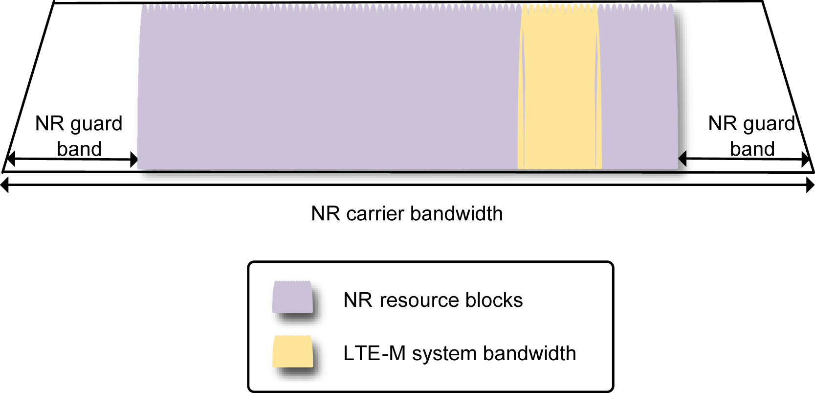
It is up to the base station implementation whether the time-frequency resource split between LTE-M and NR is completely static or more dynamic. Fig. 5.33 illustrates static resource sharing, where a small slice of the available spectrum is allocated to LTE-M and not used for NR, and the rest of the spectrum is used for NR. The slice corresponds to the number of PRBs in the configured LTE-M system bandwidth (see Table 5.4), i.e. it can be as narrow as 6 PRBs and only contain a single LTE-M narrowband if it is desired to minimize the impact on the amount of resources available for NR. If the foreseen amount of LTE-M traffic is relatively small, a static resource split between NR and LTE-M with a small LTE-M system bandwidth may be a suitable configuration.
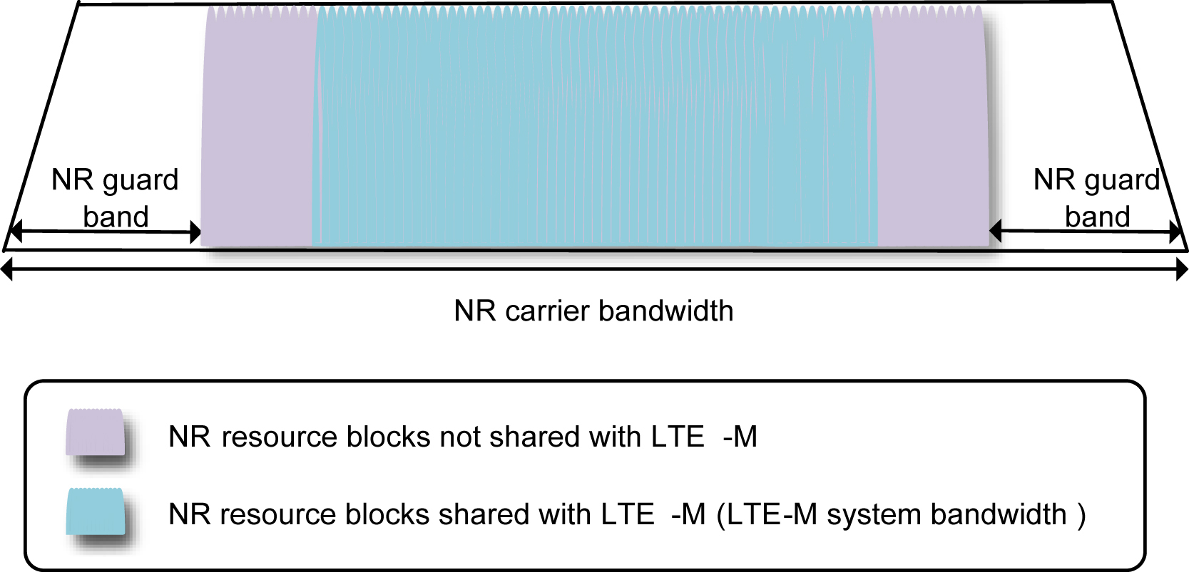
A more flexible resource sharing is illustrated in Fig. 5.34, where a large portion of the available resources serves as a common resource pool for NR and LTE-M, and it is up to the base station to allocate resources dynamically from this resource pool to NR and LTE-M devices. The shared part corresponds to the number of PRBs in the configured LTE-M system bandwidth. As shown in Table 5.4, the LTE-M system bandwidth can range from 6 to 100 PRBs and contain as few as a single narrowband or as many as 16 narrowbands. A more dynamic resource sharing has the potential to provide more efficient resource utilization through resource pooling but may require a more complex base station implementation. The standardized mechanisms for supporting static or dynamic resource sharing will be described in the remainder of this section.
Table 5.36

To ensure that LTE-M legacy devices can operate without knowing any NR-specific operation, one fundamental aspect is that an LTE-M device can identify an LTE-M cell during the initial cell selection process (see Section 5.3.1.1). To achieve this, the LTE-M carrier center frequency needs to be placed according to a 100-kHz channel raster (see Section 5.2.1.1). Furthermore, as PSS, SSS and PBCH are the signals used by the LTE-M device during cell search, they need to be preserved.
Similarly, to ensure that NR devices can operate regardless of whether there is an LTE-M carrier deployed in the same band or not, the NR carrier needs to be placed according to NR channel raster shown in Table 5.36. In most cases, the NR channel raster is 100
kHz. Furthermore, the NR synchronization signal block (SSB) needs to be preserved as it is used by the NR device during cell search.
Meanwhile, the interference between NR and LTE-M should be minimized so that the impact on NR and LTE-M performance is negligible when they are deployed in the same band. Unlike LTE and LTE-M, NR supports multiple subcarrier configurations. If the NR carrier is configured with the same subcarrier spacing as LTE-M, i.e., 15
kHz subcarrier spacing, it is desirable to align the NR and LTE-M subcarriers on the same subcarrier grids, with the frequencies of an NR subcarrier and an LTE-M subcarrier differing by an integer multiple of 15
kHz. With this, if the NR and LTE-M networks are synchronized, NR subcarriers and LTE-M subcarriers are mutually orthogonal. If the NR carrier is configured with subcarrier spacing other than 15
kHz, a guard band is needed between NR and LTE-M to ensure minimal inter-subcarrier interference.
It can be shown that for 15
kHz NR subcarrier spacing and 100
kHz NR carrier raster, every 20th NR subcarrier (i.e., every 300
kHz) relative to the NR channel raster will coincide with an LTE-M raster position [29]. One out of three possible LTE-M channel raster positions fulfills this condition. If the carrier positions are selected according to this relation, subcarrier grid alignment between NR and LTE-M is achieved in downlink (but not necessarily in uplink, which will be discussed next).
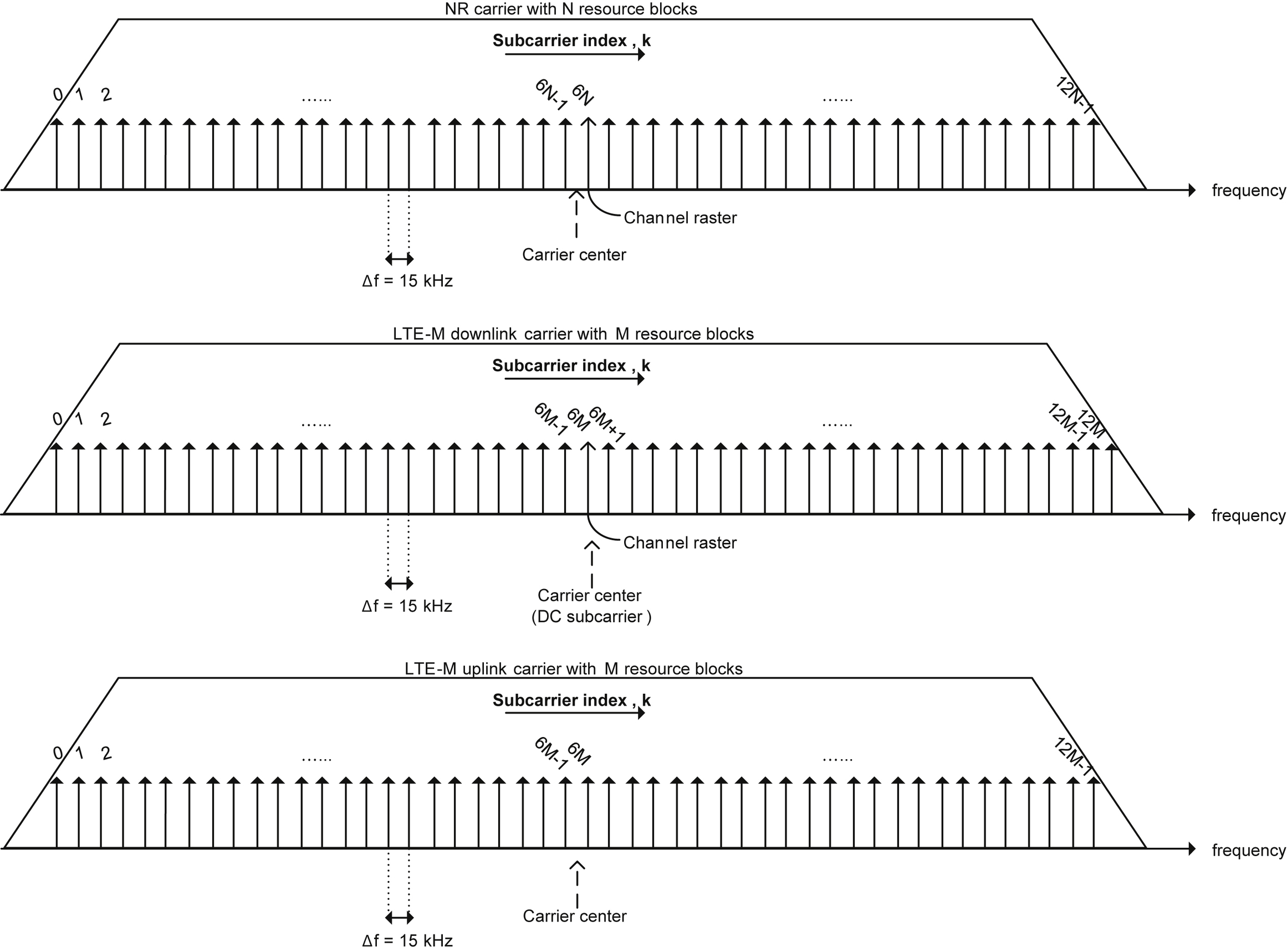
LTE-M, like LTE but unlike NR, has an unused DC subcarrier at the center of the downlink system bandwidth (see Section 5.2.2). However, no DC subcarrier is inserted in uplink. As a result, the LTE-M downlink system bandwidth is one subcarrier wider than the LTE-M uplink system bandwidth and one subcarrier wider than the NR system bandwidth. This is illustrated in Fig. 5.35. In order to achieve subcarrier grid alignment also in uplink, the DC subcarrier needs to be considered. In LTE-M, the channel raster points to the unused DC subcarrier in the center of the LTE downlink system bandwidth, whereas the NR channel raster points to an ordinary NR subcarrier near the middle of the NR carrier. For an NR carrier with N resource blocks, both in downlink and uplink there are 12
N subcarriers indexed from 0 to 12N-1, and the channel raster is mapped to subcarrier 6
N [27]. For an LTE-M carrier with M resource blocks, there are 12
M
+
1 downlink subcarriers (including the DC subcarrier) indexed from 0 to 12
M and the channel raster is mapped to subcarrier 6
M, but there are only 12
M uplink subcarriers (no DC subcarrier). In order to enable simultaneous subcarrier grid alignment between NR and LTE-M in both downlink and uplink, NR supports a configurable uplink half-subcarrier shift. When the base station has enabled this shift in the cell, a half subcarrier (+7.5
kHz) shift is applied to the NR uplink. Release 15 supports this shift in NR FDD but not in NR TDD, so coexistence between NR and LTE-M in TDD
bands cannot use this shift and instead need to rely on a sufficiently large inter-carrier guard band between NR and LTE-M.

It should be noted that due to the mentioned DC subcarrier, perfect alignment between NR resource blocks and LTE-M resource blocks is not possible. When alignment cannot be achieved, it may be necessary to reserve M +1 NR downlink resource blocks in order to fit M LTE-M resource blocks.
Collision between NR and LTE-M transmissions can be avoided by exploiting the mechanisms for resource reservation that are available in LTE-M and NR.
On the LTE-M side, the base station can use the LTE-M downlink subframe bitmap and the LTE-M starting symbol (both described in Section 5.2.4.1) to restrict the LTE-M transmissions within the cell. The downlink subframe bitmap can be used to protect periodic NR transmissions such as NR SSB, and the LTE-M starting symbol should be configured large enough to avoid collision with NR PDCCH transmissions in the beginning of the downlink subframe. Similarly, the LTE-M uplink subframe bitmap (described in Section 5.2.5.1) can be used to protect potential periodic NR uplink resources if needed.
On the NR side, the base station can use NR downlink resource reservation bitmaps to indicate to NR devices that some particular resource blocks and/or OFDM symbols are restricted
from NR PDSCH transmission. The NR devices will take these restrictions into account in the NR PDSCH rate-matching. These reservation mechanisms can be used for protecting periodic LTE-M transmissions such as PSS, SSS, PBCH, SIB1 and SI messages.
NR also supports resource element (RE) level reservation of REs occupied by LTE CRS. If the base station indicates that an LTE or LTE-M carrier is transmitted in some part of the NR carrier, the NR devices will take the LTE CRS into account in the NR PDSCH rate-matching. This mechanism is an important enabler for the more dynamic resource sharing approach illustrated in Fig. 5.34, where a portion of the NR system bandwidth can be used as a resource pool shared between NR and LTE-M, achieving the same LTE-M scheduling flexibility within an NR carrier as within an LTE carrier (as described in Section 5.1.2.6). The CRS muting feature introduced in LTE-M in Release 15 (see Section 5.2.4.3.1) can potentially be useful in this context for reducing the amount of LTE CRS transmission that needs to take place within the NR carrier.
When deciding how to use these tools for coexistence between NR and LTE-M, the foreseen traffic mix should be considered. If only a small LTE-M traffic load is expected, it may be enough to configure a small LTE-M system bandwidth, whereas LTE-M traffic with high average load or large traffic peaks may require configuration of a larger LTE-M system bandwidth. If a large LTE-M system bandwidth is configured, dynamic resource sharing (as depicted in Fig. 5.33) between LTE-M and NR may be needed in order to be able to utilize the resource efficiently, whereas static resource sharing (as depicted in Fig. 5.33) may be considered sufficiently efficient if the LTE-M system bandwidth is small enough compared to the NR system bandwidth.

