Global cellular IoT standards
Abstract
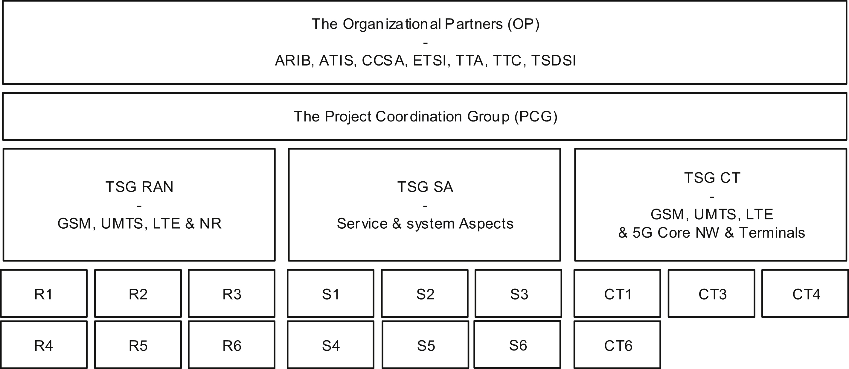
This chapter first presents the Third Generation Partnership Project (3GPP), including its ways of working, its organization, and its linkage to the world's largest regional standardization development organizations (SDOs).
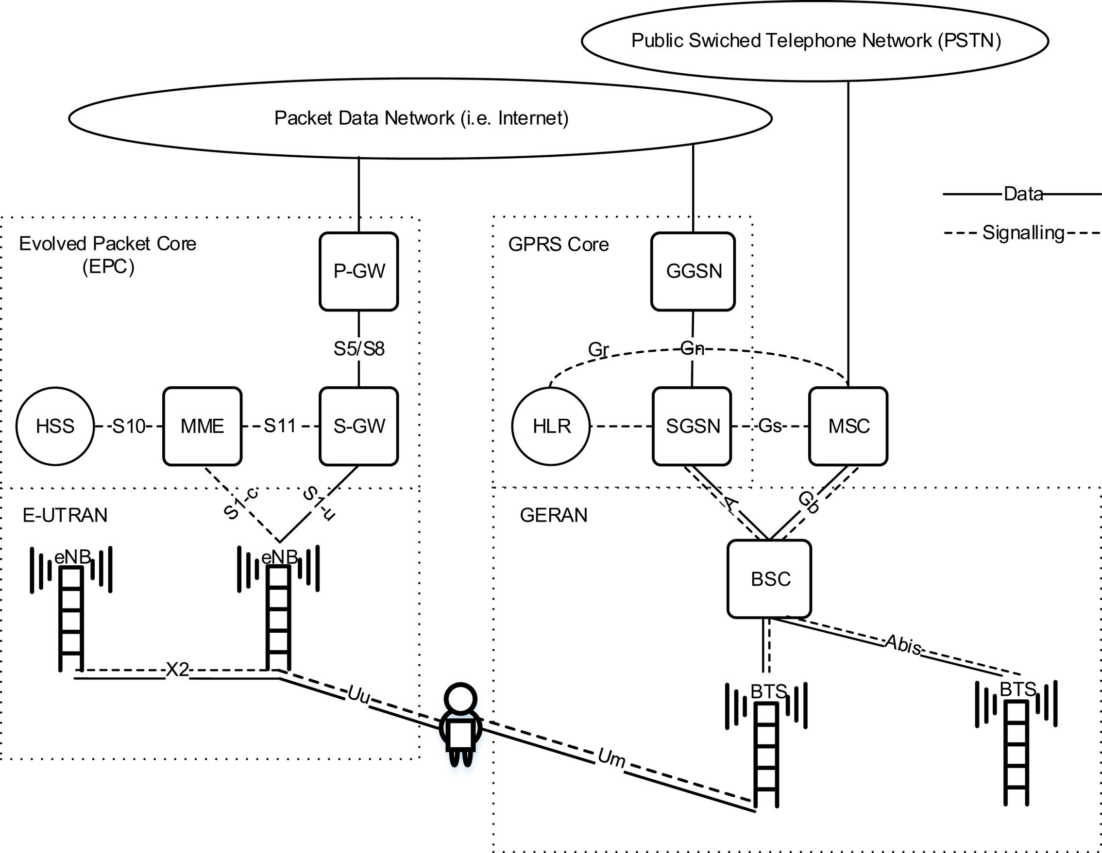
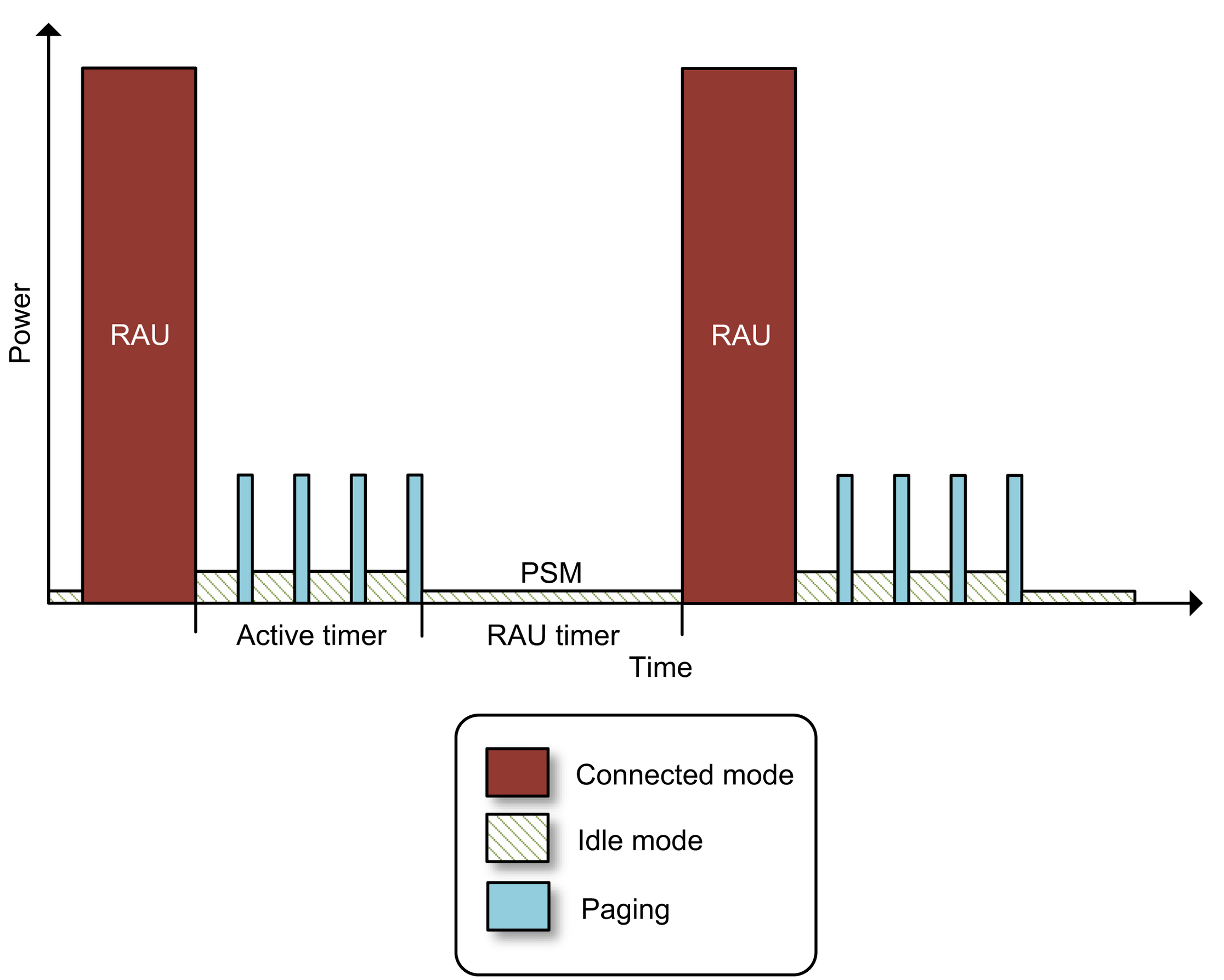
Then, after providing a basic overview of the 3GPP cellular systems architecture, 3GPP's work on Cellular IoT is introduced. This introduction includes a summary of the early work performed by 3GPP in the area of massive machine-type communications (mMTC). The Power Saving Mode (PSM) and extended Discontinuous Reception (eDRX) features are discussed together with the feasibility studies of the technologies Extended Coverage Global System for Mobile Communications Internet of Things (EC-GSM-IoT), Narrowband Internet of Things (NB-IoT), and Long-Term Evolution for Machine-Type Communications (LTE-M).
To introduce the work on critical MTC (cMTC) the 3GPP Release 14 feasibility Study on Latency reduction techniques for Long Term Evolution is presented. It triggered the specification of several features for reducing latency and increasing reliability in LTE.
Support for cMTC is a pillar in the design of the fifth generation (5G) New Radio (NR) system. To put the 5G cMTC work in a context an overview of NR is provided. This includes the Release 14 NR study items, the Release 15 normative work and the work on qualifying NR, and LTE, as IMT-2020 systems.
Finally, an introduction to the MulteFire Alliance (MFA) and its work on mMTC radio systems operating in unlicensed spectrum is given. The MulteFire Alliance modifies 3GPP technologies to comply with regional regulations and requirements specified to support operation in unlicensed frequency bands.
2.1. 3GPP
2.2. Cellular system architecture
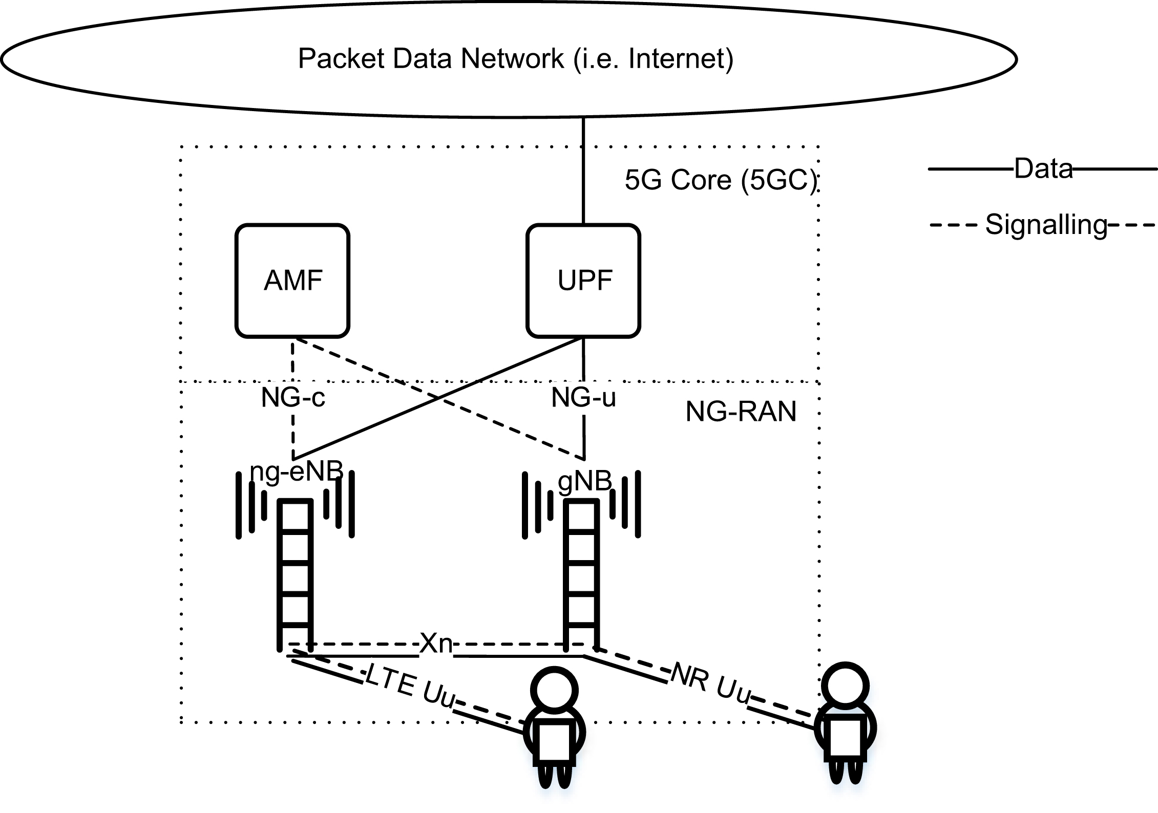
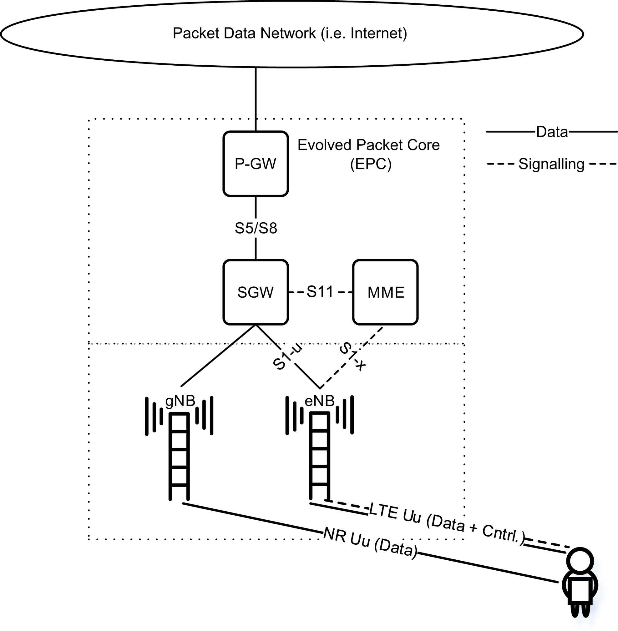
2.2.1. Network architecture
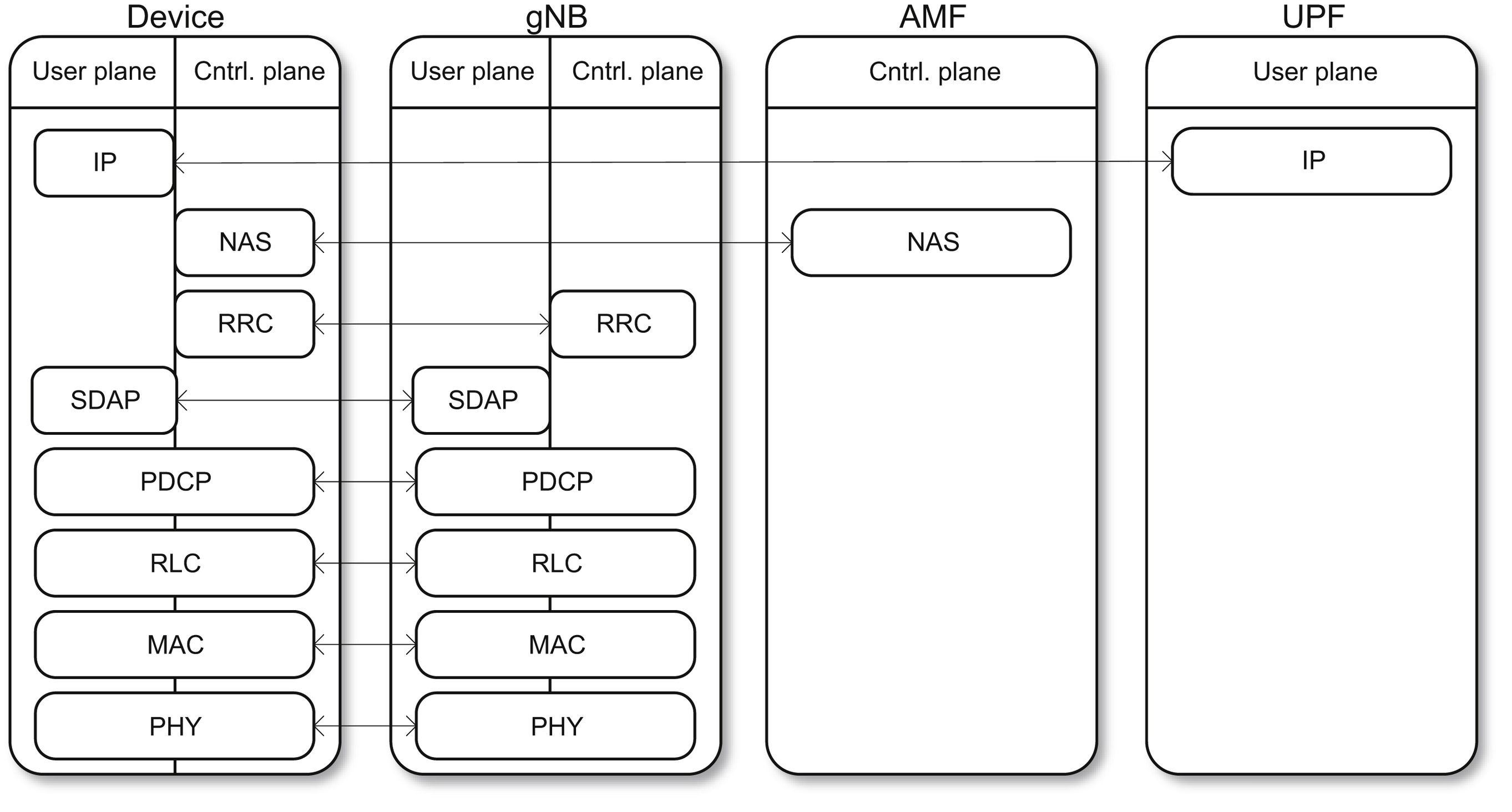
2.2.2. Radio protocol architecture
2.3. From machine-type communications to the cellular internet of things
2.3.1. Access class and overload control
Table 2.1
2.3.2. Small data transmission
2.3.3. Device power savings
2.3.4. Study on provision of low-cost MTC devices based on LTE
Table 2.2
Table 2.3
| Release | GSM | LTE |
|---|---|---|
| 12 | Power saving mode | Power saving mode |
| 13 |
Extended DRX
Power efficient operation
|
Extended DRX |
Table 2.4
| Objective | Modem cost reduction | Coverage impact |
|---|---|---|
| Limit full duplex operation to half duplex | 7%–10% | None |
| Peak rate reduction through limiting the maximum transport block size (TBS) to 1000 bits | 10.5%–21% | None |
| Reduce the transmission and reception bandwidth for both RF and baseband to 1.4 MHz | 39% | 1–3 dB DL coverage reduction due to loss in frequency diversity |
| Limit RF front end to support a single receive branch | 24%–29% | 4 dB DL coverage reduction due to loss in receive diversity |
| Transmit power reduction to support PA integration | 10%–12% | UL coverage loss proportional to the reduction in transmit power |
 (2.1)
(2.1)
Table 2.5
| Performance/Parameters | Downlink coverage | Uplink coverage | |||||
|---|---|---|---|---|---|---|---|
| Physical channel | PSS/SSS | PBCH |
PDCCH
Format 1A
|
PDSCH | PRACH |
PUCCH
Format 1A
|
PUSCH |
| Data rate [kbps] | – | – | – | 20 | – | – | 20 |
| Bandwidth [kHz] | 1080 | 1080 | 4320 | 360 | 1080 | 180 | 360 |
| Power [dBm] | 36.8 | 36.8 | 42.8 | 32 | 23 | 23 | 23 |
| NF [dB] | 9 | 9 | 9 | 9 | 5 | 5 | 5 |
| #TX/#RX | 2TX/2RX | 2TX/2RX | 2TX/2RX | 2TX/2RX | 1TX/2RX | 1TX/2RX | 1TX/2RX |
| SNR [dB] | -7.8 | -7.5 | -4.7 | -4 | -10 | -7.8 | -4.3 |
| MCL [dB] | 149.3 | 149 | 146.1 | 145.4 | 141.7 | 147.2 | 140.7 |

2.3.5. Study on cellular system support for ultra-low complexity and low throughput internet of things
Table 2.6
| # | Link direction | DL | UL |
|---|---|---|---|
| 1 | Power [dBm] | 43 | 33 |
| 2 | Thermal noise [dBm/Hz] | -174 | -174 |
| 3 | NF [dB] | 5 | 3 |
| 4 | Bandwidth [kHz] | 180 | 180 |
| 5 | Noise power [dBm] = (2)+(3)+10log10((4)) | -116.4 | -108.7 |
| 6 | Single antenna receiver sensitivity according to 3GPP TS 45.005 [dBm] | -102 @ NF 9 dB | -104 @ NF 5 dB |
| 7 | Single antenna receiver sensitivity according to 3GPP TR 45.820 [dBm] | -106 @ NF 5 dB | -106 @ NF 3 dB |
| 8 | SINR [dB] = (7)–(5) | 10.4 | 12.4 |
| 9 | RX processing gain [dB] | 0 | 5 |
| 10 | MCL [dB] = (1)-((8)–(10)) | 149 | 144 |

2.3.6. Study on Latency reduction techniques for LTE
2.4. 5G
2.4.1. IMT-2020
2.4.2. 3GPP 5G
2.4.2.1. 5G feasibility studies
Table 2.7
| mMTC connection density | cMTC latency | cMTC reliability |
|---|---|---|
| 1,000,000 device/km2 |
User plane: 1
ms
Control plane: 20
ms
|
99.999% |
Table 2.8
| Connection density | Coverage | Latency | Device battery life |
|---|---|---|---|
| 1000.0000 device/km2 | 164 dB | 10 s | 10 years |

