7.3. Idle and connected mode procedures
In this section, we describe NB-IoT idle and connected mode procedures and higher layer protocols, including all activities from initial cell selection to initiating a connection and transmitting and receiving data during the connection. This section shows how the physical layer described in Section 7.2 is utilized for supporting idle and connected mode procedures.
Like in the case of LTE-M, the idle mode procedures employed in NB-IoT include the initial cell selection, SI acquisition, cell reselection, paging procedures and PSM operation. The transition from idle to connected mode involves the procedures for random access, access control, connection establishment, and multicast. The connected mode operation includes procedures for scheduling, retransmission, power control and positioning. Idle mode procedures and connected mode procedures are described in Sections 7.3.1 and 7.3.2, respectively.
The NB-IoT radio protocol stack is inherited from LTE and is described in Section 2.2. Throughout this section, we will in most cases use an FDD network as an example to describe the radio access procedures.
7.3.1. Idle mode procedures
7.3.1.1. Cell selection
The main purpose of cell selection is to identify, synchronize to, and determine the suitability of an NB-IoT cell. Besides the initial cell selection, there are also the procedures of noninitial cell selection and cell reselection. For NB-IoT, cell reselection is used to support idle mode mobility and is described in Section 7.3.1.3. From a physical layer perspective, one of the main differences between initial and noninitial cell searches is the magnitude of carrier frequency offset (CFO) that the device has to deal with when synchronizing to a cell.
The initial cell selection is carried out by the device before it possesses any knowledge of the network and before any prior synchronization to the network has taken place. This corresponds to, e.g., the public land mobile network and cell search performed by the device on being switched on the first time. In this case, cell selection needs to be achieved in the presence of a large CFO because of the possible initial oscillator inaccuracy of the device. The initial oscillator inaccuracy for a low-cost device module may be as high as 20
ppm. Thus, for a 900
MHz band, the CFO may be as high as 18
kHz (900·106
·20·10
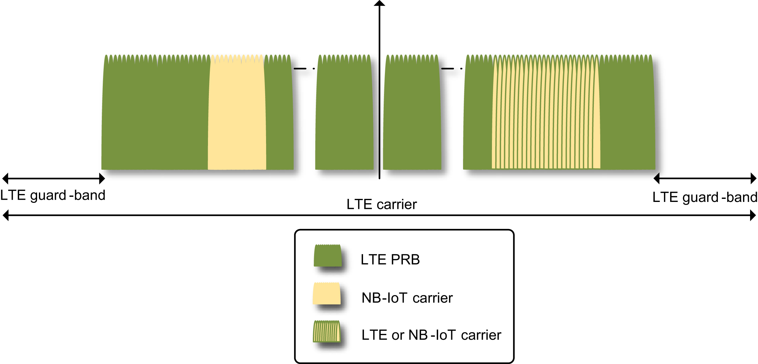
−6). Furthermore, as explained in Section 7.2.1, as the device searches for a cell on the 100
kHz raster grid, there is a raster offset of ±2.5 or ±7.5
kHz for the in-band and guard-band deployments. Thus, the magnitude of total initial frequency offset for in-band and guard-band deployments can be as high as 25.5
kHz. A brute-force search on the 100 kHz raster grid is however a painstakingly slow process. Release 15 introduces EARFCN [15] pre-provisioning, where the device is provided with information about a list of frequency candidates of NB-IoT anchor carriers. This information helps the device speed up the initial cell search process.
The noninitial cell selection, also known as stored information cell selection, is carried out by the device after previous synchronization to the network has taken place, and the device
possesses stored knowledge of the network. After the device has synchronized to the network, it has, e.g., resolved the raster offset and has corrected its initial oscillator inaccuracy. In this case, the CFO may be smaller compared with that during initial cell selection. One example for the device to perform the noninitial cell selection procedure is when the device's connection to the current cell has failed and it needs to select a new cell or when the device wakes up from sleep.
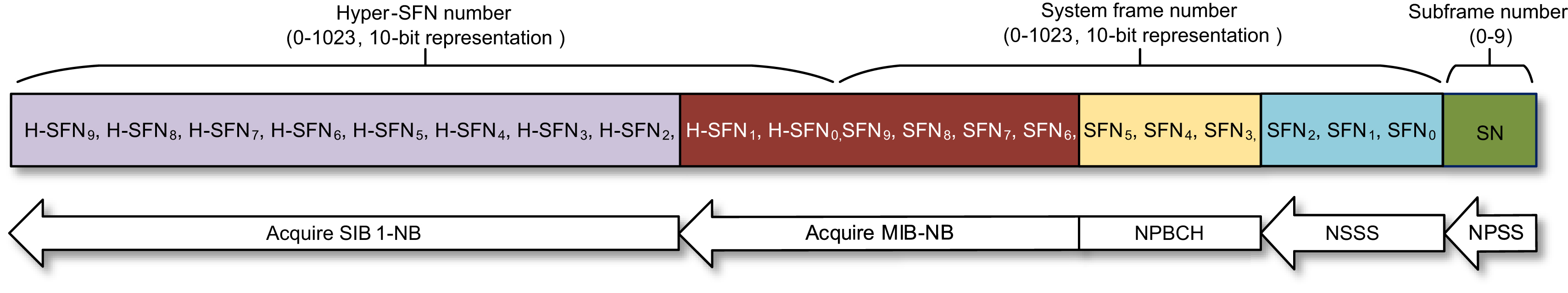
The general steps in the NB-IoT cell selection procedure are as follows:
- 1. Search for the NPSS to identify the presence of an NB-IoT cell.
- 2. Synchronize in time and frequency to the NPSS to identify the carrier frequency and the subframe structure within a frame.
- 3. Identify the PCID and the three LSBs of the SFN by using the NSSS. The relative subframe between NSSS and NPSS is used to identify whether the cell is an FDD or TDD cell.
- 4. Acquire the MIB-NB to identify the complete SFN as well as the two LSBs of H-SFN, and resolve the frequency raster offset. MIB-NB further provides information concerning how the SIB1-NB is transmitted. In a TDD cell, the MIB-NB includes information whether the SIB1-NB is transmitted on the anchor or a non-anchor carrier. In the FDD case, the SIB1-NB is always transmitted on the anchor carrier.
- 5. Acquire the SIB1-NB to identify the complete H-SFN, the PLMN, tracking area, and cell identity and to prepare for verification of the cell suitability.
These procedures are described in the next few sections in detail.
7.3.1.1.1. Time and frequency synchronization
The first two steps in the initial cell selection procedure aim to time-synchronize to NPSS and obtain a CFO estimation. In principle, they can be combined into one step of joint time and frequency synchronization. However, joint time and frequency synchronization is more costly in terms of receiver complexity. For low-end IoT devices, it is easier to achieve NPSS time synchronization first, in the presence of CFO, and once the NPSS time synchronization is achieved, the device can use additional occurrences of NPSS for CFO estimation. As shown in Figs. 7.11 and 7.39, NPSS is transmitted in subframe #5 in every frame in both FDD and TDD systems, and by time synchronizing to NPSS the device detects subframe #5 and consequently all the subframe numbering within a frame. NPSS synchronization can be achieved by correlating the received signal with the known NPSS sequence or by exploiting the autocorrelation properties of NPSS. As described in Section 7.2.4.2.1, NPSS uses a hierarchical sequence structure with a base sequence repeated according to a cover code. The NPSS detection algorithm can be designed to exploit such structure to achieve time synchronization to NPSS. Interested readers can refer to Ref. [24] for more details. Once the device achieves time synchronization to NPSS, it can find NPSS in the next frame and use it for CFO estimation. In coverage-limited condition, these two steps may rely on accumulating detection metrics over many NPSS subframes.
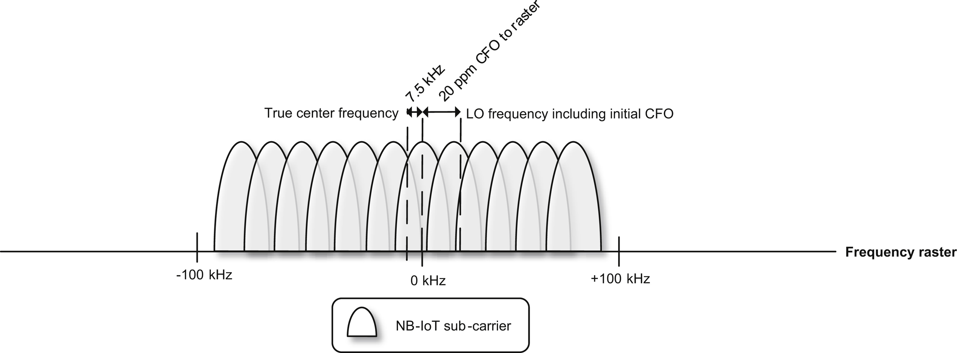
As described in Section 7.2.1.1, for in-band and guard-band deployments, there is a frequency raster offset referred to as the frequency separation between the 100
kHz raster grid, which is the basis of device searching for an NB-IoT carrier, and the actual center frequency of an NB-IoT anchor carrier. This frequency raster offset is, however, unknown to the device before the initial cell selection. The CFO contributed by the oscillator inaccuracy
is, at this stage, relative to the raster grid. As illustrated in Fig. 7.44, this may result in a needed correction of the local oscillator exceeding the oscillator-induced CFO. The additional correction is equivalent to the raster offset and thus has a magnitude 2.5 or 7.5
kHz for in-band and guard-band deployments. This means that the initial cell selection algorithm needs to be robust in the presence of a raster offset up to 7.5
kHz.
7.3.1.1.2. Physical cell identification and initial frame synchronization
The NSSS transmissions are mapped to subframe #9 in an FDD cell, or subframe #0 in a TDD cell, in every even-numbered radio frame. After NPSS synchronization, the device knows where subframe #9 or #0 is, but does not know whether a frame is even- or odd-numbered. As described in Section 7.2.4.2.2, the NSSS waveform also depends on the SFN, i.e., SFN mod 8
=
0, 2, 4, or 6. Furthermore, NSSS waveforms depend on the PCID. A straightforward NSSS detection algorithm is therefore to form 504 × 8
=
4032 hypotheses, where 504 equals the number of PCIDs used in a NB-IoT network. Each hypothesis corresponds to a hypothesized NSSS waveform during the NSSS detection period. Correlating the received signal with the NSSS waveforms based on each of these hypotheses would allow the device to detect the PCID and the three LSBs of SFN, essentially the 80
ms framing structure. In coverage-limited condition, NSSS detection may rely on accumulating detection metrics over multiple NSSS repetition intervals. For a device interested in searching for both FDD and TDD cells, it needs to repeat the NSSS detection process on subframes #9 and #0. When NSSS is successfully detected, the device knows whether the detected cell is an FDD or TDD cell.
7.3.1.1.3. MIB acquisition
After acquiring the PCID, the device knows the NRS placement within a resource block as the subcarriers that NRS REs are mapped to are determined by PCID. It can thus demodulate and decode NPBCH, which carries the NB-IoT MIB, often denoted as MIB-NB. One of the information elements carried in the MIB-NB is the four most significant bits (MSBs) of the SFN. Because the SFN is 10-bit long, the four MSBs of SFN change every 64 frames, i.e., 640
ms. As a result, the TTI of NPBCH is 640
ms. A MIB-NB is encoded to an NPBCH code block, consisting of eight CSBs. See Section 7.2.4.4. NPBCH is transmitted in subframe #0 in an FDD cell, or subframe #9 in a TDD cell, and each NPBCH subframe carries a CSB. A CSB is repeated in eight consecutive NPBCH subframes. Thus, by knowing the 80
ms frame block structure (after synchronizing to NSSS), the device knows which NPBCH subframes carry an identical CSB. It can combine these repetitions to improve detection performance in coverage extension scenarios. However, the device does not know which one of the eight CSBs is transmitted in a specific 80
ms interval. Therefore, the device needs to form eight hypotheses to decode a MIB-NB during the cell selection process. This is referred to as NPBCH blind decoding. In addition, to correctly decode the NPBCH CRC, the device needs to hypothesize whether one or two antenna ports are used for transmitting NPBCH. There is a CRC mask applied to the CRC bits of NPBCH, and the mask is selected according to 1 or 2 transmit antenna ports used for NPBCH, NPDCCH, NPDSCH transmissions. Therefore, in total 16 blind decoding trials are needed. A successful MIB-NB decoding is indicated by having a correct CRC.
When the device can successfully decode NPBCH, it acquires the 640
ms NPBCH TTI boundaries. Afterward, from MIB-NB the device also acquires the information listed below:
- • Operation mode (stand-alone, in-band, guard-band).
- • In case of in-band and guard-band, the frequency raster offset (±2.5, ±7.5 kHz).
- • Four MSBs of the SFN.
- • Two LSBs of the H-SFN.
- • Information about SIB1-NB scheduling.
- • SI value tag, which is essentially a version number of the SI. It is common for all SIBs except for SI Block Type 14 (SIB14-NB) and SI Block Type 16 (SIB16-NB).
- • Access Barring (AB) information which indicates whether AB is enabled, and in that case, the device shall acquire a specific SI (i.e., SIB14-NB, see Section 7.3.1.2.3) before initiating RRC connection establishment or resume.
The operation mode information further indicates, in the in-band case, how the NB-IoT cell is configured compared with the LTE cell. Such an indication is referred to as same PCI indicator. If the same PCI indicator is set true, the NB-IoT and LTE cells share the same PCID, and NRS and CRS have the same number of antenna ports. One implication is that in this case, the device can also use the LTE CRS for channel estimation. As a result, when the same PCI indicator is set true, MIB-NB further provides information about the LTE CRS sequence. On the other hand, if the same PCI indicator is set false, the device still needs to know where the CRSs are in a PRB. For the in-band mode, there is a required relationship between the PCIDs of LTE and NB-IoT in that they need to point to the same subcarrier indexes for CRS and NRS. Thus, the device already knows the subcarrier indexes for CRS by knowing the PCID of the NB-IoT cell. However, it does not know whether the LTE CRS has the same number of antenna ports as NRS or it has four antenna ports. Knowing this is important as NPDCCH and NPDSCH are rate-matched according to the number of CRS REs in a PRB. The information concerning whether the LTE cell uses four antenna ports or not is carried in the MIB-NB.
7.3.1.1.4. Cell identity and H-SFN acquisition
After acquiring the MIB-NB, including the scheduling information about SIB1-NB, a device is able to locate and decode SIB1-NB. We will describe more about how the device acquires SIB1-NB in Section 7.3.1.2.1. From a cell selection perspective, it is important to know that the SIB1-NB carries the eight MSBs of the H-SFN, the PLMN, tracking area, and a 28-bit long cell identity, which is used to unambiguously identify a cell within a public land mobile network. Thus, after acquiring SIB1-NB, the device has achieved complete synchronization to the frame structure shown in Fig. 7.7. Based on the cell identifiers, the device is able to determine if it is allowed to attach to the cell. It will finally be able to evaluate the suitability of the cell against a pair of minimum required signal strength and signal quality threshold parameters broadcasted in SIB1-NB. A suitable cell is a cell that is sufficiently good to camp on, but it is not necessarily the best cell. The cell reselection procedure described in Section 7.3.1.3 supports the selection of the best available cell for optimizing link and system capacity.
Fig. 7.45 illustrates and summarizes how the device acquires complete framing information during the initial cell selection procedure.
After completing the initial cell selection, the device is expected to have a time-accuracy within a few microseconds and a residual frequency offset within 50
Hz. In essence, the device has achieved time and frequency synchronization with residual errors that will not result in significant performance degradation in subsequent transmission and reception during idle and connected mode operations.
7.3.1.2. SI acquisition
After selecting a suitable cell to camp on, a device needs to acquire the full set of SI messages. This procedure and the information associated with the eleven NB-IoT SI messages are presented in the next few sections.
7.3.1.2.1. System Information Block Type 1
The content and importance of SIB1-NB have already been indicated in Section 7.3.1.1.4. Table 7.23 presents in more detail the information acquired by the device on reading SIB1-NB.
The scheduling information of SIB1-NB carried in MIB-NB describes the TBS (208, 328, 440, or 680 bits) and number of repetitions (4, 8, or 16) used for SIB1-NB transmissions. With such information, the device knows how to receive SIB1-NB.
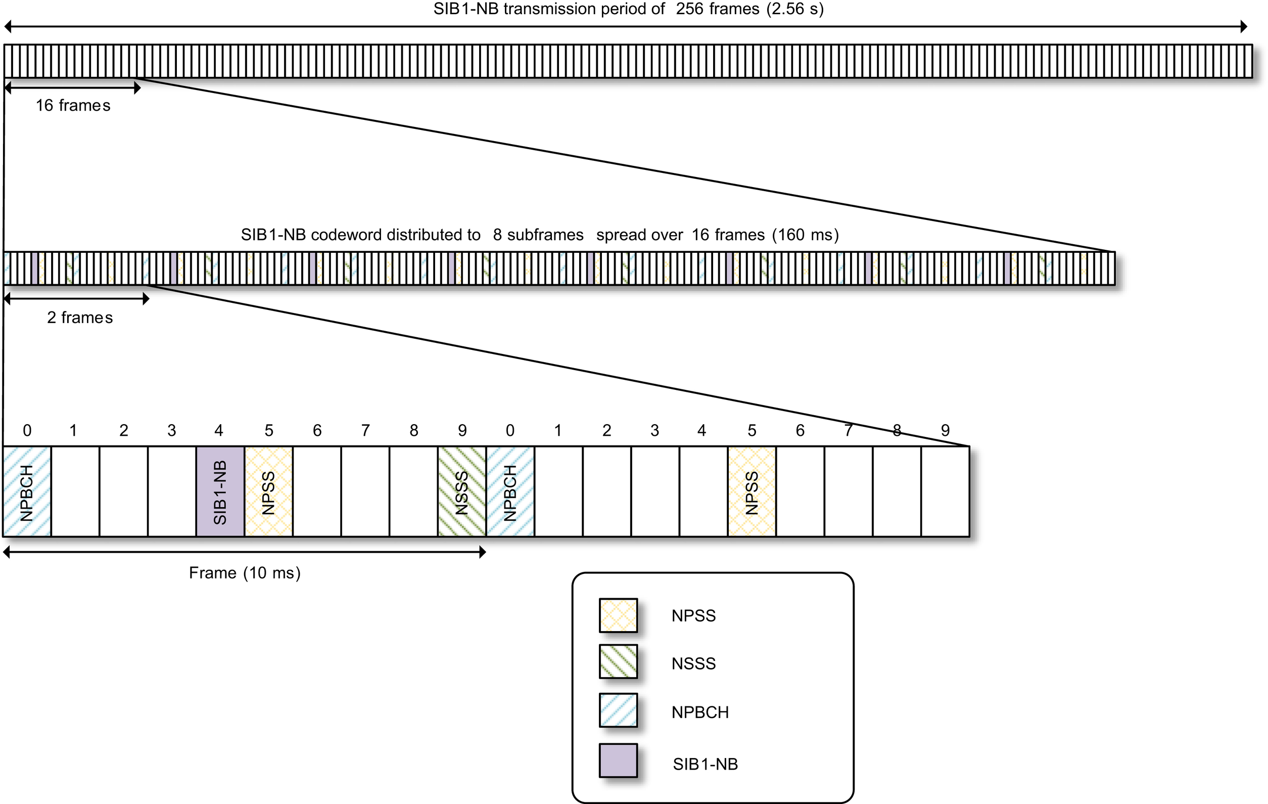
The transmission of SIB1-NB in an FDD cell is illustrated in Fig. 7.46. A SIB1-NB TB is carried in eight SIB1-NB subframes, mapped to subframe #4 in every other frame during a 16-frame interval. These 16 frames are repeated 4, 8, or 16 times. The repetitions are evenly spread over the SIB1-NB transmission interval, which is defined as 256 frames, i.e., 2.56
s.
To reduce SIB1-NB acquisition time for devices at extremely poor coverage locations, 3GPP Release 15 introduces an option to also use subframe #3 for SIB1-NB transmissions in an FDD cell. This option is indicated in MIB-NB, and when it is enabled every subframe #3 immediately preceding a subframe #4 carrying SIB1-NB is also used for SIB1-NB transmissions. The codeword mapped to subframe #3 is obtained based on a rate-matching process, which in essence extends the codeword mapped to subframe #4 by continuing the circular buffer reading process, see Ref. [8].
There is a notion of SIB1-NB modification period, which equals to 40.96
s. The SIB1-NB content is not supposed to change within a SIB1-NB modification period. Thus, the same SIB1-NB TB is repeated in all SIB1-NB transmission periods within a modification period. In the next SIB1-NB modification period, the content is allowed to change. However, in practice, excluding the changes of the H-SFN bits, such changes occur rarely.
The starting frame for SIB1-NB in a transmission period depends on the PCID as well as the aforementioned SIB1-NB repetition factor signaled in MIB-NB. The motivation of having
different starting frames in different cells is to randomize interference and avoid persistent intercell interference between the transmissions of SIB1-NB in different cells.
Table 7.23
7.3.1.2.2. Information specific to in-band mode of operation
For the in-band mode, an NB-IoT device needs to acquire certain LTE carrier parameters to be able to know which resources are already taken by LTE, and in cases when CRS may be used for assisting measurements and channel estimation, the device needs to know the relative power between CRS and NRS as well as the sequence information of CRS. As explained in Section 7.3.1.1.3, some of this information is provided by MIB-NB. Additional information is carried in SIB1-NB. By acquiring SIB1-NB, the device is able to have the complete information it needs to figure out the resource mapping within a PRB for the case of in-band operation. Table 7.24 provides a list of such information.
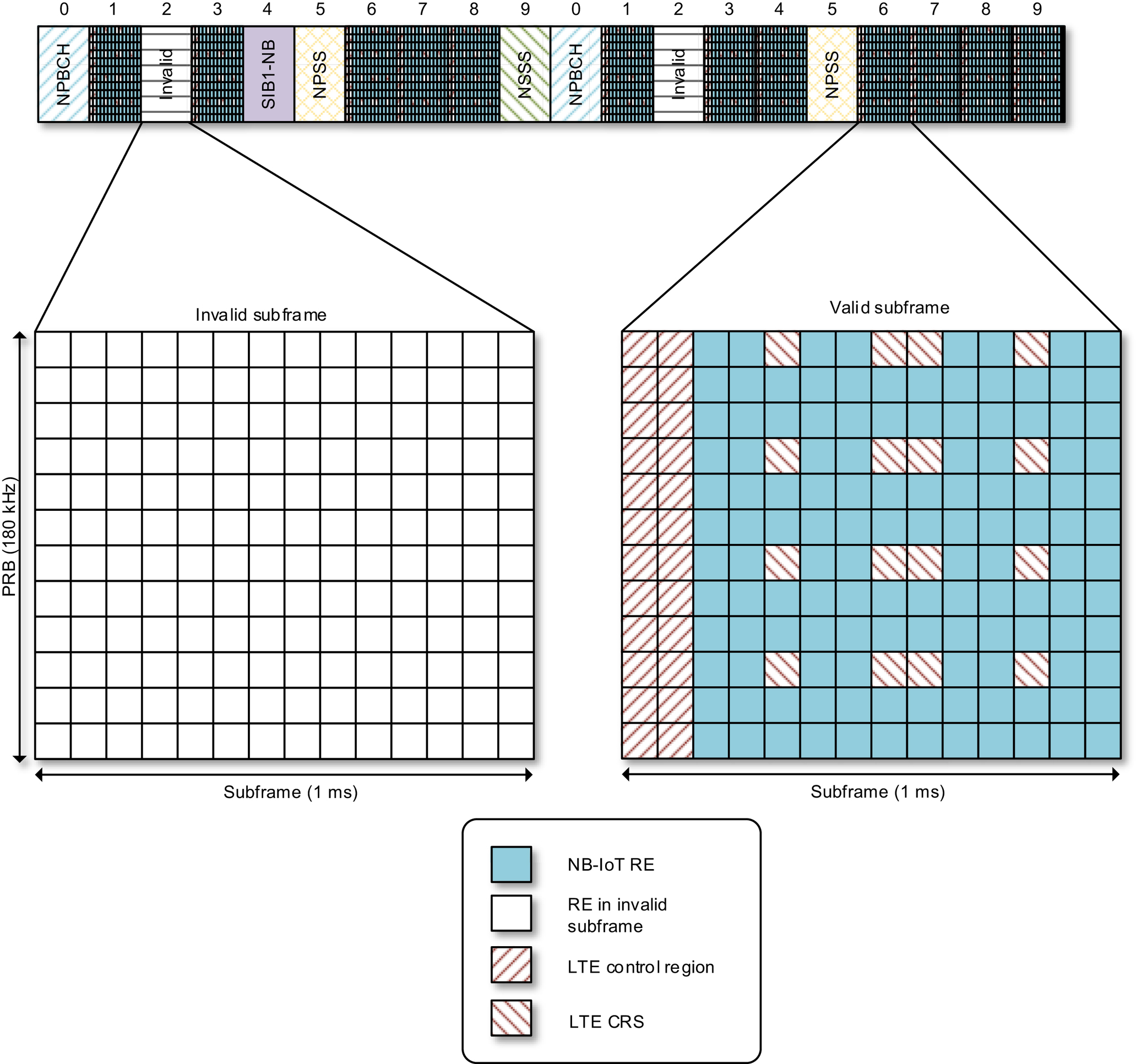
The valid subframe bitmap as explained in Section 7.2.4.1 is used to indicate which downlink subframes within a 10 or 40 subframes interval can be used for NB-IoT. This can be used, for example, to avoid collision with LTE MBSFN.
When a Release 15
cell configures subframe #3 for additional SIB1-NB transmissions, subframe #3 will be declared as an invalid subframe to avoid a legacy device mapping NPDCCH or its scheduled NPDSCH to a SIB1-NB subframe. However, a Release 15 device knows exactly which subframes #3 are used for SIB1-NB and which are not. Thus, a Release 15 device will still treat subframes #3 that are not used for SIB1-NB transmissions as valid, and map NPDCCH or its scheduled NPDSCH to them.
An example is given in Fig. 7.47. The NB-IoT devices use the provided information about LTE configuration in terms of control region, antenna ports, and CRS to not make use of resources taken by LTE. The remaining resources can be used for NB-IoT downlink.
7.3.1.2.3. SI blocks 2, 3, 4, 5, 14, 15, 16, 20, 22, 23
After reading the SI scheduling information in SIB1-NB, the device is ready to acquire the full set of SI messages. In addition to SIB1-NB, NB-IoT defines ten additional types of SIBs as listed in Table 7.25. Interested readers can refer to Ref. [11] for additional details regarding these SIBs.
Table 7.24
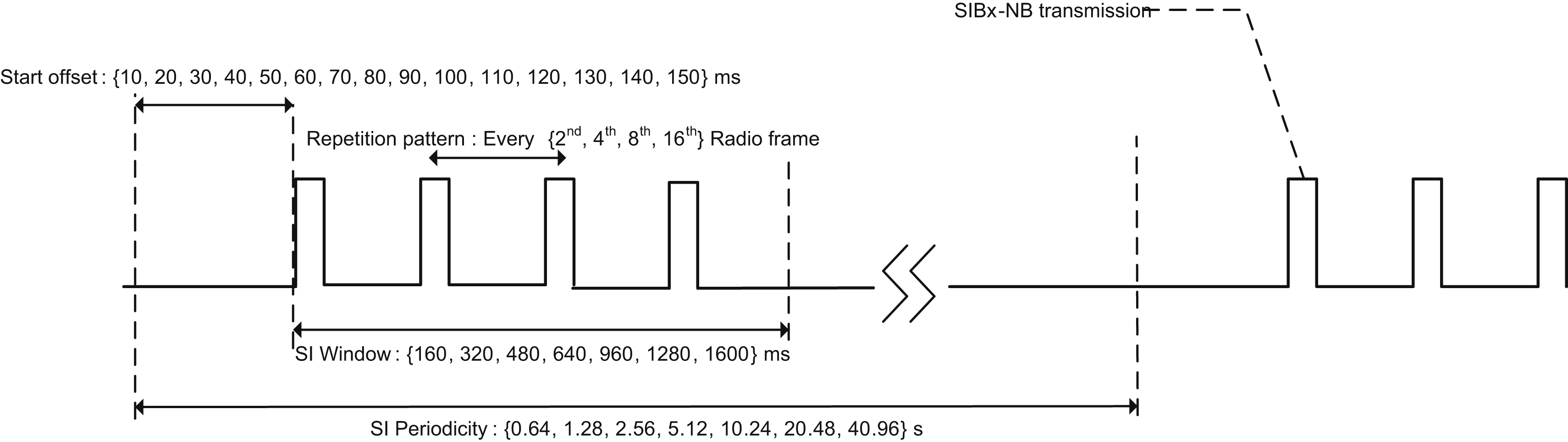
SIBs 2, 3, 4, 5, 14, 15, 16, 20, 22, 23 are periodically broadcasted during specific time-domain windows known as the SI windows. SIB1-NB configures a common SI window length for all SIBs and schedules periodic and nonoverlapping occurrences of the SI windows.
To support a variable content across the SI messages as well as future extension of the messages, each SI message is configured with a TBS selected from the set of {56, 120, 208, 256, 328, 440, 552, 680} bits. While the two smallest sizes are mapped over two consecutive NB-IoT subframes, the six largest are mapped over eight consecutive NB-IoT subframes.
Furthermore, to support operation in extended coverage, a configurable repetition level of the SIBs is supported. Each SIB can be configured to be repeated every second, fourth, eighth, or 16th radio frame. The total number of repetitions depends on the configured SI window
length and the repetition pattern. For the largest SI window of 160 frames, up to 80 repetitions are supported. Fig. 7.48 illustrates the transmission of an NB-IoT SI message.
Table 7.25
| System information block | Content |
|---|---|
| SIB2-NB | RRC information for all physical channels that is common for all devices. |
| SIB3-NB | Cell reselection information that is common for intrafrequency and interfrequency cell reselection. It further provides additional information specific to intrafrequency cell reselection such as cell suitability related information. |
| SIB4-NB | Neighboring cell-related information, e.g., cell identities, relevant only for intrafrequency cell reselection. |
| SIB5-NB | Neighboring cell-related information, e.g., cell identities and cell suitability-related information, relevant only for interfrequency cell reselection. |
| SIB14-NB | Access class barring information per PLMN. Contains a specific flag for barring of a specific access class. It also indicates barring of exception reporting. (see Section 7.3.1.9) |
| SIB15-NB | SC-PTM related information, including a list of additional frequency bands applicable for the cells participating in the SC-PTM transmission. SC-PTM is described in Section 7.3.1.11. |
| SIB16-NB | Information related to GPS time and Coordinated Universal Time (UTC). |
| SIB20-NB | SC-MCCH configuration information. SC-MCCH is described in Section 7.3.1.11. |
| SIB22-NB | Radio resource configuration for paging and random access procedures on non-anchor carriers. (See Section 7.3.1.10) |
| SIB23-NB | Radio resource configuration for NPRACH resources using preamble Format 2 on non-anchor carriers. (See Section 7.2.5.1) |
SIB1-NB indicates the latest status of each of the scheduled SIBs. A change in the content of a SIB is indicated in the MIB-NB, with a few exceptions, as described in Section 7.3.1.2.4, and may optionally also be indicated in SIB1-NB. This allows a device to determine if a specific SI block needs to be reacquired.
7.3.1.2.4. SI update
The value tag (5 bits) provided in MIB-NB serves as content version number and is to be considered valid for 24
h by the devices. Different version numbers correspond to different SI contents. When the SI has changed, the network can explicitly notify the devices. A device in the idle mode with a DRX cycle shorter than the modification period has the option to monitor the paging messages for SI change notifications. Paging will be discussed in Section 7.3.1.4. There might be cases where the device has not been notified about the SI changes before it attempts to access the network, e.g., in case the device has been configured with a DRX cycle longer than the modification period, in case the device uses PSM (see Section 7.3.1.5) during idle mode, or in case the base station does not transmit any paging at SI change. Such a potential problem is addressed by requiring the device to always read the
MIB-NB on an access attempt. By reading the MIB-NB, the device will realize that there is an SI change through the SI value tag. This also allows the device to acquire information regarding the barring status as explained in Section 7.3.1.9. Note, however, that changes in SIB14-NB (AB parameters) and SIB16-NB (information related to GPS time and UTC) will not result in an SI value tag change. This is because the information carried in SIB14-NB and SIB16-NB changes more frequently, but has no implication or relationship to other system information. It is therefore advantageous to make such changes independent of the SI value tag.
7.3.1.3. Cell reselection
After selecting a cell, a device is configured to monitor up to 16 intrafrequency neighbor cells and up to 16 neighbor cells on an interfrequency. In simple words, in case the device detects that a neighbor cell has become stronger in terms of the NRS received power (NRSRP) than the currently serving cell, then the cell reselection procedure is triggered. Devices that are in good coverage, i.e., experience a sufficiently high NRSRP level in the serving cell, can be excluded from measuring for cell reselection. This helps improve the battery life of these devices.
Besides securing that a device camps on the best cell, the cell reselection procedure is the main mechanism for supporting idle mode mobility. During the connected mode, the device does not need to perform mobility measurements on the serving or on the neighboring cells. In case the signal quality of the serving cell becomes very poor, resulting in persistent link-level failures, the device will invoke the link-layer failure procedure, which in essence moves it from the connected mode back to the idle mode. In the idle mode, the device can use the cell reselection mechanism to find a new serving cell. After establishing a new serving cell, the device can start a random access procedure (see Section 7.3.1.6) to get back to the connected mode to complete its data reception and transmission.
The cell reselection measurement in the NB-IoT case is referred to as NRSRP measurement, as it intends to reflect the received power level of NRS. For devices in poor coverage, it may take many downlink subframes to acquire an NRSRP estimate of required accuracy. This consumes device energy. In 3GPP Release15, an enhancement was introduced to allow NRSRP measurements to be based on NSSS and NPBCH. Using these additional signals, the time required for obtaining a sufficiently accurate NRSRP measurement is reduced. Another enhancement introduced in 3GPP Release 14 is to make it possible for the device to completely skip NRSRP measurement for the support of mobility during 24
h after the device confirms the variation in NRSRP measurements in its current cell is less than a threshold. This enhancement was introduced in recognizing that a majority of the NB-IoT devices are stationary, and therefore performing frequent cell reselection measurement is not necessary.
These features help improve device energy efficiency during idle mode.
7.3.1.4. Paging, DRX and eDRX
The monitoring of paging during the idle mode has implications on device battery lifetime and the latency of downlink data delivery to the device. A key to determining the impact is how often a device monitors paging. NB-IoT does just as LTE use search spaces for defining paging transmission opportunities. The search space concept, including the Type-1 common
search space (CSS) implementation used for paging indication, is covered in detail in Section 7.3.2.1.
For now, it is sufficient to note that a device monitors a set of subframes defined by the Type-1 CSS to detect an NPDCCH containing a DCI of format N2 that schedules a subsequent NPDSCH containing a paging message addressed to the device. The P-RNTI is the identifier used to address a device for the purpose of paging and is, as described in Section 7.2.4.5, used to scramble the NPDCCH CRC.
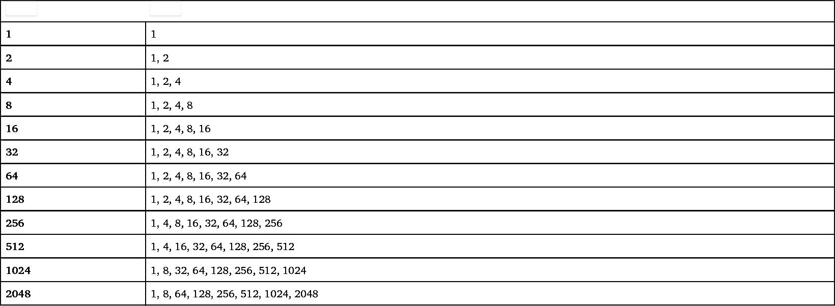
The starting subframe for a Type-1 CSS candidate is determined from the location of NB-IoT PO subframe, which is determined based on the configured DRX cycle [25]. If the starting subframe is not a valid NB-IoT downlink subframe, then the first valid NB-IoT downlink subframe after the PO is the starting subframe of the NPDCCH repetitions. The Type-1 CSS candidates are based on only NPDCCH AL 2 described in Section 7.2.4.5. A search space contains NPDCCH candidates defined for repetition levels R up to a configured maximum NPDCCH repetition level R
max. R
max is typically configured to secure that all devices in a cell can be reached by the paging mechanism, and the relation between the possible repetition levels R for a configured R
max is given by Table 7.26.
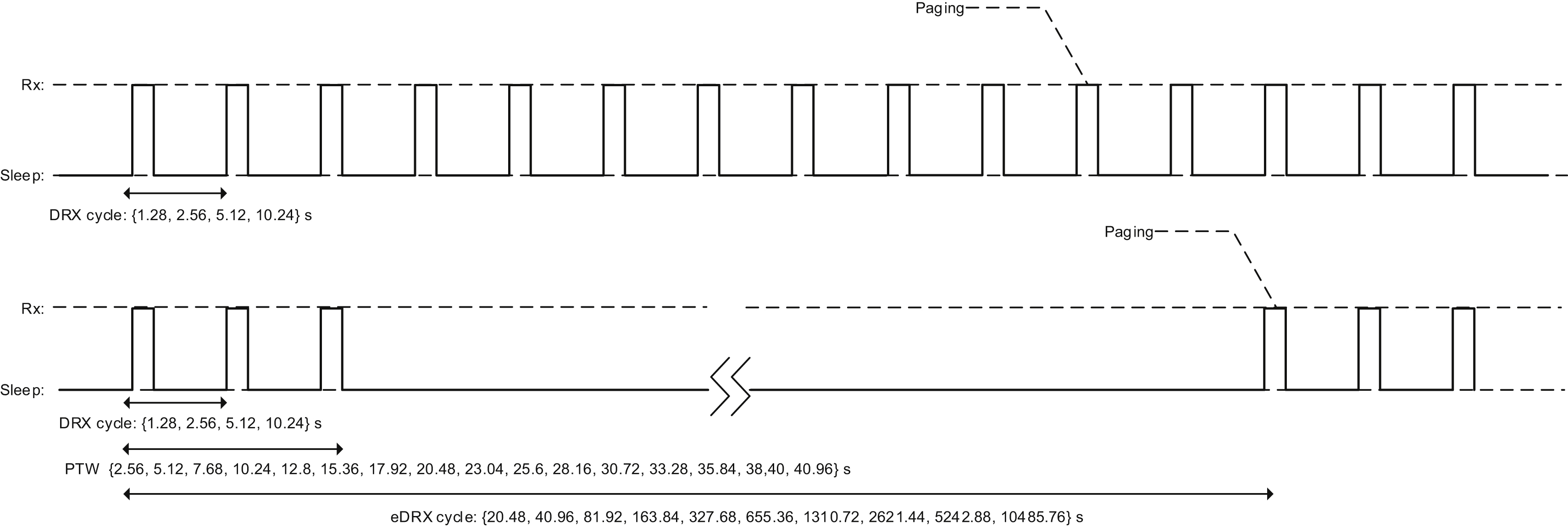
Fig. 7.49 illustrates possible paging configurations in NB-IoT. Either DRX or eDRX can be used. In case of DRX, the POs occur with a periodicity of at most 10.24
s. For eDRX, the longest eDRX period is 2
h, 54
min, and 46
s, which corresponds to one hyperframe cycle. After each eDRX cycle a paging transmission window starts during which downlink reachability is achieved through the configured DRX cycle.
NB-IoT when introduced in 3GPP Release 13 only supported paging on the anchor carrier. To enable NB-IoT to support mobile terminated reachability for a very high number of users, paging support was added to non-anchor carriers in 3GPP Release 14. Radio resource
configuration for paging on non-anchor carriers is provided in SIB22-NB. A device selects its paging carrier based on its device identity.
Table 7.26

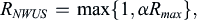
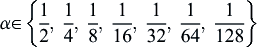
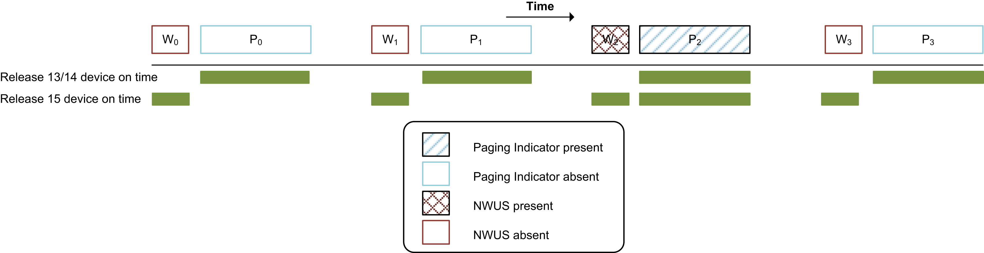
Device battery lifetime is one of the most important performance objectives that NB-IoT aims to achieve. To further improve device battery lifetime, 3GPP Rel-15 introduced NWUS (see Section 7.2.4.8). The NWUS facilitates device energy saving by indicating whether a paging indicator will be sent in an associated PO. As this in essence is a single bit information (i.e., paging indicator present or not present), the total transmission time required is much shorter than that required for NPDCCH with DCI format N2. The number of repetitions for NWUS,
R
N
W
U
S
 , is a fraction of the maximum number of repetitions configured for NPDCCH for paging,
R
max
 :
:
, is a fraction of the maximum number of repetitions configured for NPDCCH for paging,
:
where
α
∈
{
1
2
,
1
4
,
1
8
,
1
16
,
1
32
,
1
64
,
1
128
}
 .
.
.Thus, NWUS enables the device to go back to sleep sooner, thereby achieving energy saving. An NWUS can be associated with more than one PO for achieving even bigger energy saving. An example is illustrated in Fig. 7.50, where a device wakes up periodically during time durations P0, P1, P2, and P3 to monitor for paging, but only finds a paging indicator during duration P2. In Release 15, an NWUS is used to indicate whether an associated PO will have a paging indicator present. As illustrated in Fig. 7.50, NWUS is transmitted in duration W2 to indicate a paging indicator will be present in duration P2. Thus, in this case, the device wakes up during durations W0, W1, W2, and W3 to look for NWUS, and as it detects NWUS during duration W2, it goes on to receive the paging indicator during duration P2. The total duration that the device wakes up in this case is much shorter than the combination of durations P0, P1, P2, and P3. The time gap between the NWUS and the associated paging occasion (where the NPDCCH starts) is configurable. When NWUS is used with either DRX or eDRX, a “short” gap length of 40, 80, 160 or 240 ms can be configured, but in the eDRX case it is also possible to configure a “long” gap length of 1 or 2 seconds.
The detection of NWUS is very straightforward, and thus it is feasible to have a dedicated, special baseband receiver wake up for NWUS detection and leave the rest of the hardware, including the ordinary receiver, in deep sleep. The aforementioned configuration of a longer gap between the NWUS and the associated paging occasion in the eDRX ensures that there is sufficient time for the device's ordinary receiver to start up and be ready to detect the NPDCCH once an NWUS was indeed detected. With such a wake-up receiver approach, additional energy efficiency improvement can be achieved. Furthermore, the design of the NWUS waveform and repetition allows a device to perform efficient re-synchronization after it wakes up. This can also contribute to energy efficiency improvement.
7.3.1.5. PSM
Some applications have very relaxed requirements on mobile terminated reachability (e.g. longer than a day) and then power consumption can be further reduced compared with using eDRX, which has a maximum eDRX cycle close to 3
h. For this type of devices, the most energy-efficient state of operation is the power saving mode (PSM) which is available for devices in RRC idle mode.
In PSM a device uses the smallest possible amount of energy. Essentially it only needs to leave its real time clock running for keeping track of time and scheduled idle mode events
such as the TAU timer. The device aborts energy consuming idle mode operations such as mobility measurements in PSM and will not transmit or monitor paging and need not keep an up-to-date synchronization to the network. The duration of PSM is configurable and may be more than a year in the most extreme configuration. The device exits PSM once it has uplink data to transmit or is mandated to send a TAU upon expiry of the TAU timer. The TAU is used as a tool for tracking a device. It informs the network of which cell the device camps on. After its uplink transmission, the device may enter DRX mode for a short period of time, configured by the active timer, for monitoring paging to enable mobile terminated reachability. After such a short duration in which the device monitors paging, the device enters the next PSM period. This procedure is illustrated in Fig. 2.6. PSM was introduced in 3GPP Release 12 as general improvement for devices with high requirements on long battery life and is described in more details in Section 2.3.3.
7.3.1.6. Random access in idle mode
NB-IoT random access procedure is generally the same as LTE. We will in this section mainly highlight aspects that are unique to NB-IoT.
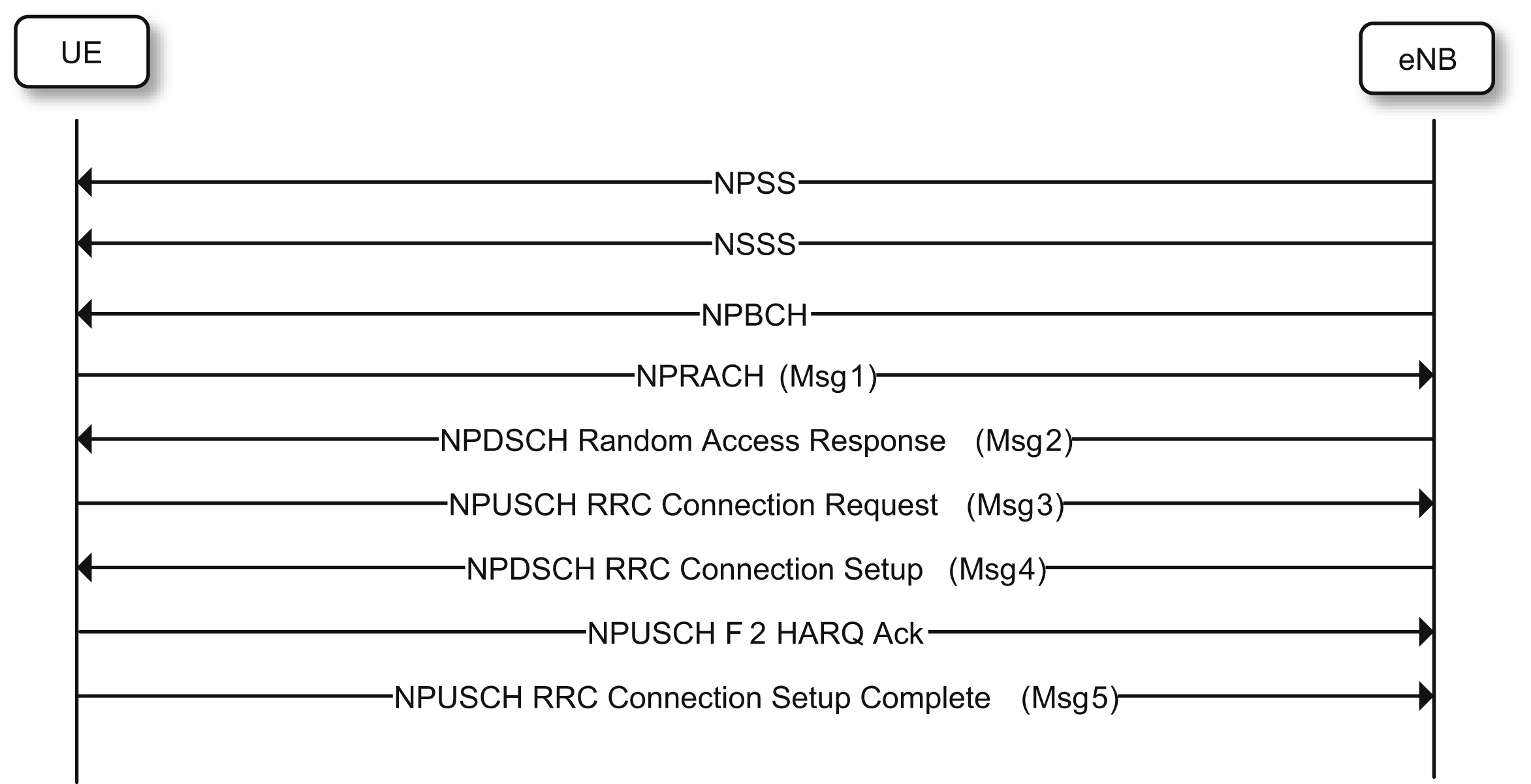
The random access procedure is illustrated in Fig. 7.51. After synchronizing to the network and confirming that access is not barred, the device sends a random access preamble using NPRACH.
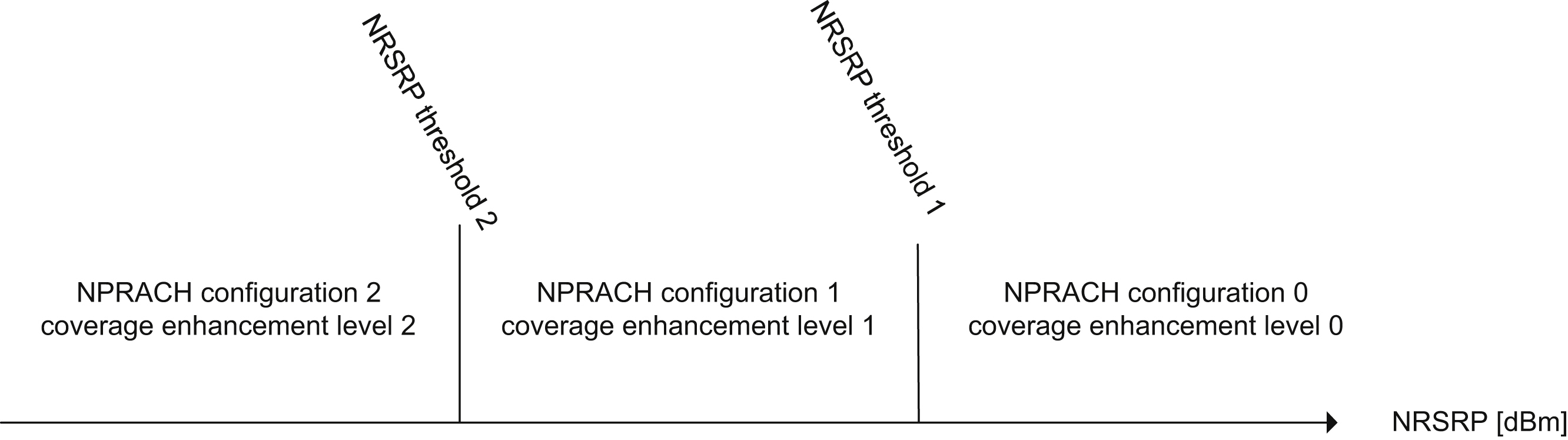
The device needs to determine an appropriate NPRACH configuration according to its coverage class estimation. Recall that SIB2-NB carries RRC information as explained in Section 7.3.1.2.3. One of the RRC information elements is the NPRACH configuration. The cell can configure up to two NRSRP thresholds that are used by the device to select the NPRACH configuration appropriate for its coverage class. An example is given in Fig. 7.52, in which two NRSRP thresholds are configured and therefore there are three NPRACH configurations for three CE levels, respectively. Essentially, the network uses these NRSRP thresholds to configure the coupling losses associated with each of the different CE levels. If the network does not configure any NRSRP threshold, the cell supports only a single NPRACH configuration used by all devices regardless of their actual path loss to the serving base station.
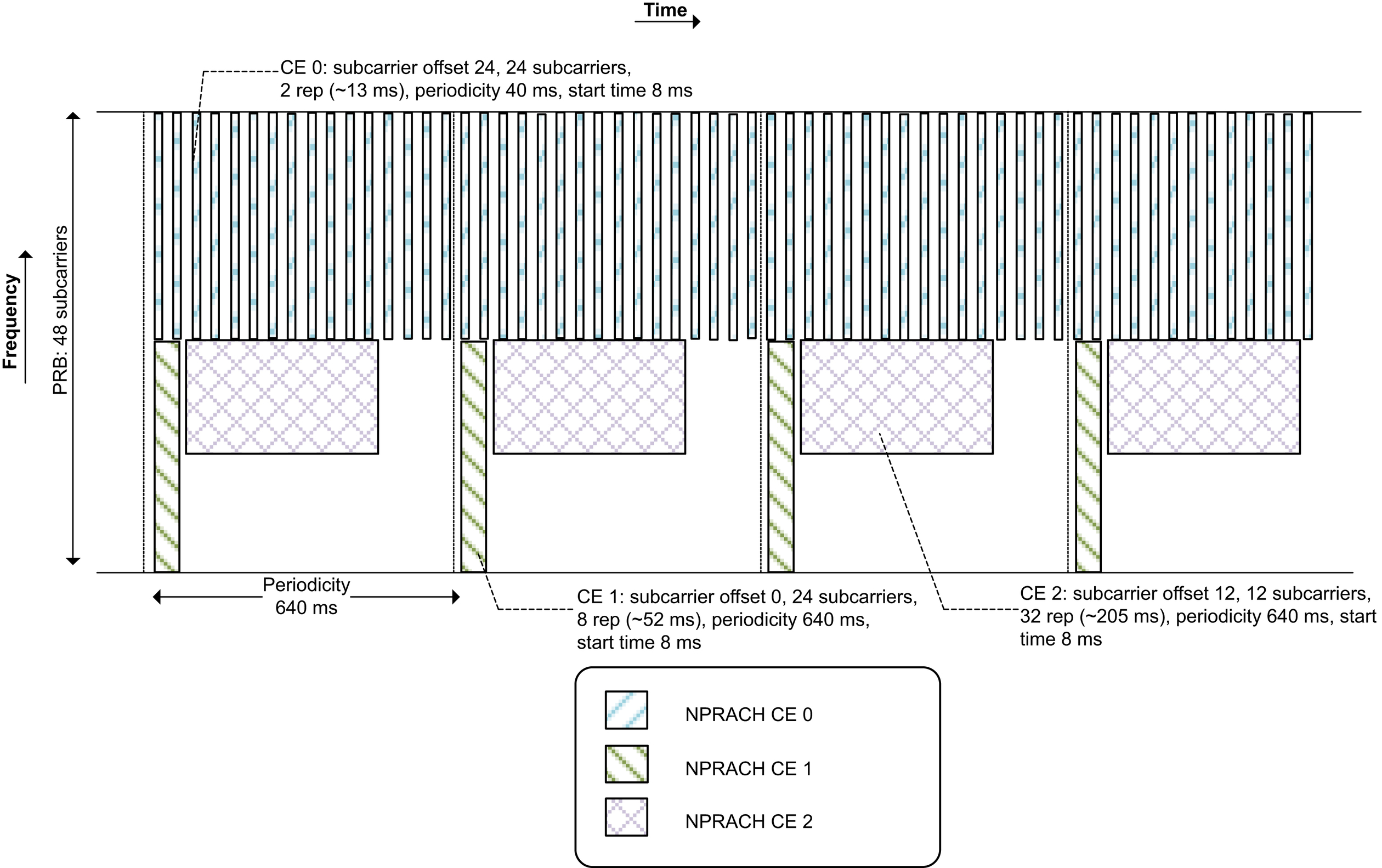
The SIB2-NB NPRACH configuration information for each CE level includes the time–frequency resource allocation. The resource allocation in the frequency domain is a set of starting preambles. Each starting preamble is equivalent to the first NPRACH symbol group and associated with a specific 3.75
kHz or 1.25
kHz tone, depending on the NPRACH format configured. The set of starting preambles is determined by a subcarrier offset and a number of subcarriers. The time-domain allocation is defined by a periodicity, a starting time of the period, and the number of repetitions associated with the NPRACH resource. This is exemplified in Fig. 7.53 where an NPRACH configuration intended to support a high access load is illustrated.
This set of starting preambles may further be partitioned into two subsets. The first subset is used by devices that do not support multitone NPUSCH transmissions for Message 3, whereas the second subset is used by devices that are capable of multitone transmissions for Message 3. In essence, the device signals its NPUSCH multitone support by selecting the NPRACH starting preamble according to its capability.
If the base station detects an NPRACH preamble, it sends back a random access response (RAR), also known as Message 2. The RAR contains a TA parameter. The RAR further contains scheduling information pointing to the radio resources that the device can use to transmit a request to connect, also known as Message 3. Note that at this point the base station already knows the device multitone transmission capability, and thus resource allocation for Message 3 will account for the device multitone transmission capability. In Message 3, the device will include its identity as well as a scheduling request. The device will always include its data volume status and power headroom in Message 3 to facilitate the base station scheduling and power allocation decision for subsequent transmissions. The data volume and power headroom report together form a Medium Access Control (MAC) control element. In Message 4, the network resolves any contention resulting from multiple devices transmitting the same random access preamble in the first step and transmits a connection setup or resume message. At this point the devices acknowledges the reception of Message 4 and makes the transition from RRC idle to RRC connected mode. The first message in RRC connected mode is the RRC Connection Setup Complete message.
The random access procedure initiates the RRC connection establishment. The classic LTE establishment procedure is introduced in Section 2.3.2 and shown in Fig. 2.5. It includes both negotiation of AS security and RRC configuration of the connection. For devices for which small infrequent data transmission is the dominating use case, Release 13 and 15 introduces three optimizations reducing the connection setup signaling. These are described in the next section.
7.3.1.7. Connection establishment
7.3.1.7.1. RRC resume
The first method for signaling reductions is known as the RRC Suspend Resume procedure, or just the RRC Resume procedure. It is part of the User Plane CIoT EPS optimizations. It allows a device to resume a connection previously suspended including the PDCP state, the AS security and RRC configurations. This eliminates the need to negotiate AS security as well as configuring the radio interface, including the data radio bearers carrying the data over the air interface, at connection setup. It also supports the PDCP to make efficient use of its Robust Header Compression already from the first data transmission in a resumed connection.
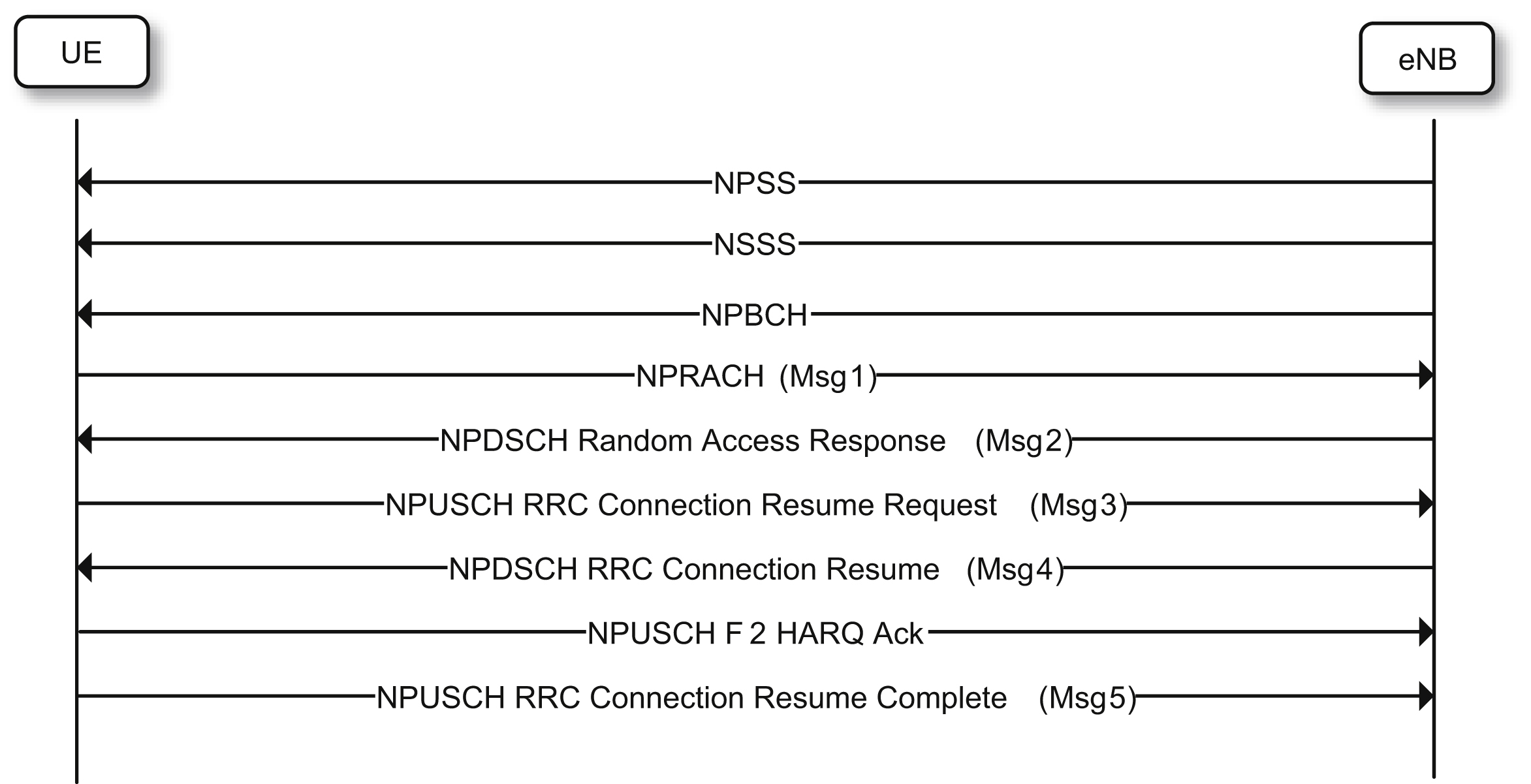
This functionality is based on a resume identity which identifies a suspended connection. It is signaled in the RRC Connection Release message from the network to a device when a connection is suspended. The device signals the resume identity back to the network when it wants to resume a connection using Message 3 including the RRC Connection Resume Request message. Fig. 7.54 illustrates the complete procedure.
The RRC resume procedure allows uplink data to be multiplexed with the RRC signaling already in Message 5. This multiplexing between Radio Link Control (RLC) packet data units containing user data and control signaling is achieved in the MAC layer.
7.3.1.7.2. Data over Non-access Stratum
The second method known as the DoNAS procedure, which stands for Data over Non-Access Stratum (NAS), makes use of the LTE Release 8 connection setup message flow shown in Fig. 7.51. It is part of the Control Plane CIoT EPS optimization. In Message 5, the RRC Connection Setup Complete message, a NAS container is used for transmitting uplink user data over the control plane. This violation of the LTE protocol architecture, shown in Fig. 2.3, with a control plane for signaling and a user plane for data, was motivated by the reduction in signaling it achieves.
For the NAS interface, which terminates in the Mobility Management Entity (MME), security is negotiated when a device attaches to a network. This means that data sent in an NAS container is both integrity protected and ciphered. As a result, AS security needs not to be configured during connection establishment. Furthermore, as the NAS signaling is sent over a signaling radio bearer (SRB) with a default configuration, it also means that a data radio bearers for user plane data transmission needs not to be configured. To support uplink and downlink transmissions after the connection establishment procedure Release 13 specifies two RRC messages (UL/DL information transfer) that only carry a NAS container where user data can be inserted.
Since DoNAS does not provide a secure link over the AS, it does not support a reconfiguration of the RRC parameters configuring a connection. As a consequence, it is important to be able to correctly assess the radio quality and provide an accurate RRC configuration of the radio link already at connection setup. Since DoNAS transfers data over an SRB the quality of service frame work developed for LTE DRBs does also not apply. This simplification was motivated by the assumption that DoNAS is mainly intended for supporting small and short data transmissions.
For Cat-NB devices the support for DoNAS is mandatory. Support for data transmission over the user plane is an optional feature, but advisable to support for providing efficient operation for use cases beyond short infrequent data transmission.
7.3.1.7.3. Early Data Transmission
For a Release 13 or 14 device, uplink data and downlink data can at the earliest be delivered in Message 5 and Message 6, respectively. This leaves room for further enhancements. 3GPP Release 15 introduces a feature called Early Data Transmission (EDT) that allows a device to transmit its uplink data in Message 3. In this case, the device can complete its data transmission in idle mode without a need to transition to connected mode.
EDT is however limited to small data payloads. Uplink EDT supports a TBS of 328, 408, 504, 584, 680, 808, 936, or 1000 bits. Although these TB sizes are not very large, they are nevertheless significantly larger than the TBS of 88 bits used in a conventional (non-EDT) Message 3. The EDT configuration in a cell, including the maximum allowed EDT TBS, is provided in SIB2-NB. A device can use the EDT procedure to transmit its uplink data only when the number of payload bits is less than the maximum TBS permitted. A device indicates its intent to use EDT by initiating a random access procedure with an NPRACH preamble randomly selected from a set of preambles configured for the EDT procedure. In this case, upon detecting the NPRACH preamble, the base station knows that the device attempts to transmit its uplink data through EDT, and therefore can include an EDT uplink grant for Message 3 in Message 2. However, it is also possible for the base station to reject the device's EDT request. The EDT uplink grant includes information about the modulation and coding scheme (MCS) and number of repetitions (Rmax) associated with the maximum TBS size (TBSmax).
As an option, the network may allow the device to select a TBS among a set of allowed TBS values. For example, if the configured maximum EDT TBS is 936 bits, the set of allowed TBS values can be {328, 504, 712, 936} [27]. From this set, the device can select a TBS for Message 3 based on its data buffer status. This option reduces the amount of padding if the device data buffer has much fewer bits than the configured TBSmax. When the device selects a TBS less than TBSmax, it needs to reduce the number of repetitions compared to that provided in
the uplink grant message. For example, if it selects a lower TBS, e.g. TBSmax/K, it reduces the number of repetitions to Rmax/K. Depending on Rmax, the reduced repetition factor Rmax/K needs to be rounded up to either the nearest integer or the nearest integer which is a multiple of 4. To support the option of device-selectable TBS, the base station needs to blindly detect the TBS used in Message 3 among a number of TBS hypotheses. Depending on the EDT configuration, the number of TBS hypotheses can be 2, 3, or 4.
EDT also support downlink data transmission in Message 4. This may be used to provide an application layer acknowledgment to the Message 3 uplink transmission.
EDT is in Release 15 enabled for mobile originated access both for the User Plane CIoT EPS optimization procedure and Control Plane CIoT EPS optimization procedure. The user plane version builds on the RRC Resume procedure and makes use of the RRC Connection Resume Request in Message 3. Message 4, including potential downlink data, is defined by the RRC Connection Release message in case the connection is suspended or released immediately following the uplink data transmission. For the control plane solution, a pair of new RRC messages were defined for Message 3 and 4. Both of them include the needed NAS container carrying the data on an SRB over the NAS.
7.3.1.8. Channel quality reporting during random access procedure
As described in Section 7.3.1.6, a device initializing the random access procedure needs to determine an appropriate NPRACH configuration according to its coverage class estimation. The coverage estimation is based on NRSRP since the network set thresholds for determining the device coverage class are based on NRSRP. An example is given in Fig. 7.52. In the subsequent downlink messages during the remainder of the random access and connection establishment procedure, the coverage class of the NPRACH selected by the device is used by the network to determine the repetition factors of NPDCCH and NPDSCH.
There are a number of issues with this solution. First, there can be at most three NPRACH configurations. Thus, the network only knows the device's downlink received signal strength coarsely. Second, there might be a pronounced difference between the received signal strength and the downlink received signal-to-interference-plus-noise ratio (SINR), which in practice is more relevant for determining the number of repetitions required for NPDCCH and NPDSCH. Note that the downlink SINR can be also different from uplink SINR as the interference may be asymmetric between downlink and uplink. Not being able to more accurately determine the repetition levels needed for NPDCCH and NPDSCH may result in failures in downlink messages during the random access and connection establishment procedure. It also influences the ability of the network to configure the NPDCCH device specific search space periodicity (see Section 7.3.2.1), which will limit the achievable data rate in RRC Connected mode. The network may configure NPDCCH and NPDSCH with a more aggressive repetition factors, although this result in inefficiency in downlink resource utilization. Most NB-IoT devices are based on the Control Plane CIoT EPS optimization solution (see section 7.3.1.7.2) which does not support a reconfiguration of the radio link after the initial configuration. It is therefore of special importance in NB-IoT to start the connection with a correct link configuration.
To address these issues, 3GPP Release 14 introduced a feature that allows the device to include its downlink channel quality estimate as an RRC information element in Message 3 or Message 5 during the random access and connection establishment procedure. For Message
3 this quality reporting is provided by the device in terms of the number of repetitions needed for NPDCCH to secure reliable operation. The device can, e.g., obtain such an estimate when it receives the RAR in Message 2, as in that process the device knows how many repetitions it needs to decode the NPDCCH scheduling the RAR. Two reporting formats are supported. The first one allows the device to indicate one of the NPDCCH repetition factors, i.e. 1, 2, 4, 8, 16, 32, 64, 128, 256, 512, 1024, or 2048 (See Section 7.2.4.5). The device can also indicate a null, i.e. that no measurement was performed. This requires a 4-bit message. In addition, for some Message 3 types with a limited space, a short format is used. With the short format, the device indicates its NPDCCH repetition estimate relative to the maximum NPDCCH repetition factor configured for the search space,
R
max
. The reported downlink channel quality can be
R
m
a
x
/
8
 ,
,
R
max
, or
4
R
m
a
x
 . The device can also indicate a null, i.e. no measurement reporting. Thus, the short channel quality reporting format requires a 2-bit message.
. The reported downlink channel quality can be
,
, or
. The device can also indicate a null, i.e. no measurement reporting. Thus, the short channel quality reporting format requires a 2-bit message.In Message 5, which is not constrained in size in the same way as Message 3, the downlink signal strength and downlink signal quality in terms of NRSRP and NRSRQ are reported by the device to the network. The intention behind this reporting is to allow the network to, in a long term, configure and plan the cells in a network in a suitable manner.
It should be noticed that the reporting described in this section is, together with the power headroom reporting, the HARQ ACK/NACK and the RLC Acknowledged Mode status reports, the only feedback sent from a NB-IoT device to the network.
7.3.1.9. Access control
Access Barring (AB) is an access control mechanism adopted in NB-IoT; it closely follows the Access Class Barring functionality described in Section 2.2 and allows PLMN-specific barring across 10 normal and 5 special access classes. It also supports special treatment of devices intending to transmit an Exception report. The Exception report concept was introduced in 3GPP Release 13 to allow a network to prioritize reports of high urgency transmitted by a device.
An AB flag is provided in the MIB-NB. If it is set false, then all devices are allowed to access the network. If the AB flag is set true, then the device must read the SIB14-NB before it attempts to access the network, which provides the just introduced access class–specific barring information. The device needs to check whether its access class is allowed to access the network. In case the device is barred, it should back off and then reattempt access at a later point in time.
A device in bad coverage locations requires a high repetition factor to be configured for its dedicated physical channels. During high network loads, it may be desirable to bar devices in bad coverage locations and use the available resources to serve many more devices in good coverage locations. 3GPP Release 15 introduces coverage-level-specific barring to prevent devices at certain coverage level, or worse, from accessing the network. This is enabled by providing an NRSRP threshold in SIB14-NB. If a device has measured NRSRP below this threshold, it is barred from accessing the network. It should back off and then reattempt access at a later point in time.
It should be noted that when the MIB-NB AB flag toggles, there is no impact on the SI value tag. See the discussion in Section 7.3.1.2.4.
7.3.1.10. System access on non-anchor carriers
The basic design of NB-IoT aimed at supporting at least 60,680 devices per km2. From 3GPP Release 14 the target was increased to support 1,000,000 devices per km2 as a consequence of a desire to make NB-IoT a 5G technology. Based on the traffic model described in Section 4.6, these loads can be assumed to correspond to 6.8 and 112.2 access arrivals per second, respectively. To keep the collision rate of competing preambles low, a sufficiently high amount of radio resources needs to be reserved for the NPRACH.
For slotted type of access schemes such as the NB-IoT NPRACH a collision probability between competing preambles can be estimated as [26]:
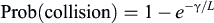 (7.22)
where L is the total number of random access opportunities per second and γ is the average random-access intensity. If a collision probability of 1% is targeted for a random-access intensity of 6.8 access arrivals per second, the total number of random access opportunities provided by the system needs to be set at 677 per second. NB-IoT can at most provide 1200 access opportunities per second by configuring a NPRACH resource for CE level 0 spanning 48 sub-carriers and reoccurring with a periodicity of 40
ms. It is clear that already this requires the NPRACH to consume a large portion of the available uplink resources. If a collision rate of 10% are acceptable, it is sufficient to configure 65 access opportunities per second. But in order to support 112.2 access arrivals per second, even a 10% collision rate will require the configuration of 1065 access opportunities per second. This in combination with the required support of devices in extended coverage motivated the introduction of random access on the non-anchor carriers. To also support mobile terminated reachability for a very high number of users, also paging support was added to the non-anchor carriers in 3GPP Release 14. The paging carrier is besides paging used for Message 2 and 4 transmissions, while the random-access carrier is used for both Message 1 and 3 transmissions. Radio resource configuration for paging and random access procedures on non-anchor carriers is provided in SIB22-NB (see Section 7.3.1.2.3).
One main difference between system access on a non-anchor carrier versus on an anchor carrier is the presence of NRS. More details on this aspect can be found in Section 7.2.4.3.
7.3.1.11. Multicast
In order to offer improved support of firmware or software updates, a group message delivery type of service known as Single Cell Point to Multipoint (SC-PTM) was introduced in NB-IoT Release 14. It builds on the Multimedia Broadcast Multicast Service architecture and provides the air interface for delivering single-cell broadcast and multicast transmissions. It shares design with LTE-M SC-PTM, described in Section 5.3.1.9.
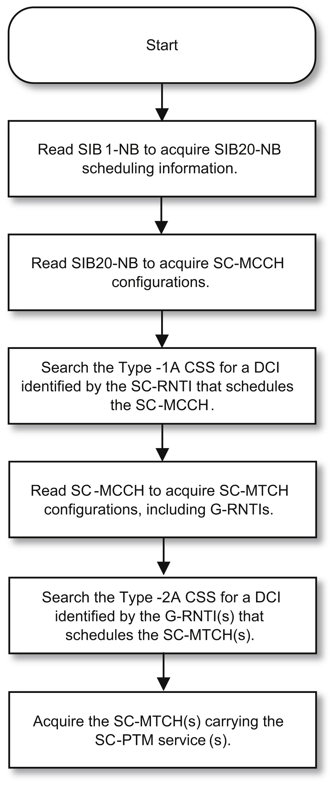
SC-PTM defines two logical channels: Single Cell Multicast Control Channel (SC-MCCH) and Single Cell Multicast Traffic Channel (SC-MTCH). These logical channels are mapped on the NPDSCH. The NPDSCH is scheduled by the NPDCCH which is transmitted in two new common search spaces associated with the SC-MCCH and SC-MTCH. The Type-1A Common Search Space (CSS) contains NPDCCH candidates, with the CRC scrambled by the Single Cell RNTI (SC-RNTI) that schedules the NPDSCH carrying the SC-MCCH. As SC-MCCH is similar to paging, i.e. it is broadcasted to a group of devices in a cell, the design of
Type-1A CSS is based on Type-1 CSS, where the NPDCCH candidates can only start at the beginning of the search space.
Type-2A CSS contains NPDCCH candidates, with the CRC scrambled by the Group RNTI (G-RNTI), that schedules the NPDSCH carrying the SC-MTCH. To maintain scheduling flexibility for the SC-MTCH, the design principle of Type-2 CSS is followed by Type-2A CSS, where several starting points are defined for the NPDCCH candidates. The search space concept is described in details in Section 7.3.2.1.
The procedure of acquiring SC-PTM services is illustrated in Fig. 7.55. As shown in Fig. 7.55, if a device is configured by higher layer to receive an SC-PTM service, upon reading SIB1-NB, the device identifies the scheduling information of SIB20-NB. The SIB20-NB contains the information required to acquire the SC-MCCH configurations associated with transmission of SC-PTM in the cell. In SC-MCCH, a device can further find the configuration
information of the SC-MTCH that carries the multicast service a device is interested in. One SC-MCCH can be configured in a cell, and it may configure up to 64 simultaneous multicast and broadcast services transmitted over the SC-MTCH. Both anchor and non-anchor carriers can be used to carry SC-MCCH and SC-MTCH.
Retransmissions are not supported for the multicast packages, and therefore for each SC-PTM session, there is only a single transmission on the NPDSCH. Due to the high number of repetitions supported by the NPDCCH and NPDSCH, an MCL of 164
dB can still be expected to be supported by NB-IoT SC-PTM services.
7.3.2. Connected mode procedures
7.3.2.1. NPDCCH search spaces
A key concept related to connected mode scheduling as well as idle mode paging is the NPDCCH search spaces. A search space consists of one or more subframes in which a device may search for DCI addressed to the device. There are three major types of search spaces defined:
- • Type-1 Common Search Space (CSS), used for monitoring paging. There is a variant of Type-1 CSS, namely Type-1A CSS, used for monitoring the scheduling of SC-MCCH.
- • Type-2 CSS, used for monitoring RAR, Message 3 HARQ retransmissions and Message 4 radio resource assignments. There is a variant of Type-2 CSS, namely Type-2A CSS, used for monitoring the scheduling of SC-MTCH.
- • User equipment-specific search space (USS), used for monitoring downlink or uplink scheduling information
The device however is not required to simultaneously monitor more than one type of search space.
Type-2 CSS and USS share many commonalities in search space configurations. Thus, we will focus on Type-2 CSS and USS in this section. Section 7.3.1.4 already presents the use of the Type-1 CSS.
Key parameters for defining NPDCCH search spaces for Type-2 CSS and USS are listed below:
For Type-2 CSS, the parameters R
max, α
offset, and G are signaled in SIB2-NB, whereas for USS these parameters are signaled through device-specific RRC signaling. For Type-2 CSS, R
max should be adapted according to the NPRACH coverage class it is associated to. For USS, R
max can be optimized to serve the coverage of the connected device. There is a restriction that a search period must be more than four subframes, i.e., T
>
4.
Within a search period, the number of subframes that the device needs to monitor is R
max and the number of search space candidates defined is also based on R
max. Note that the R
max subframes that the device needs to monitor within a search period have to exclude the
subframes used for transmitting NPBCH, NPSS, NSSS, and SIB1-NB. Furthermore, these subframes need to be NB-IoT subframes according to the valid subframe bitmap described in Sections 7.3.1.2.1. Table 7.27 shows the USS candidates for different R
max values and NCCE ALs.
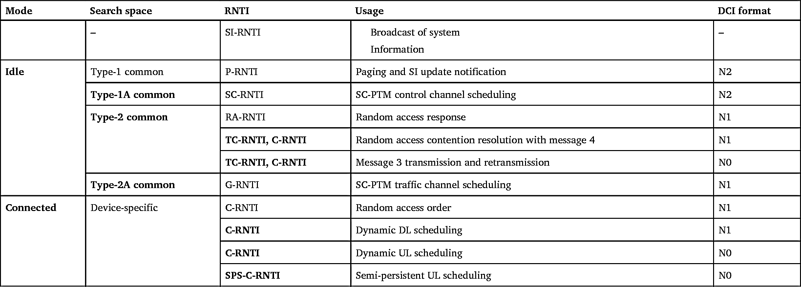
As described in Section 7.2.4.5, the CRC bits attached to DCI are also used for differentiating between different types of DCI and for identifying the device that the DCI is intended for. This is done by scrambling the CRC bits based on the different Radio Network Temporary Identifiers (RNTIs). Table 7.28 lists the combinations of NPDCCH search space, DCI format, and RNTI.
Describing the search space concept is done best with a concrete example. We will use a USS example to illustrate all the search space aspects we have discussed up to this point. Consider, for example, a device in coverage conditions requiring the NPDCCH to be transmitted with up to 2 repetitions. R
max will in this case be set to 2. It is further assumed that the scheduling periodicity is configured to be eight times longer than the maximum repetition interval, i.e., G is set to 8. Finally, an offset α
offset of 1/8 is selected.
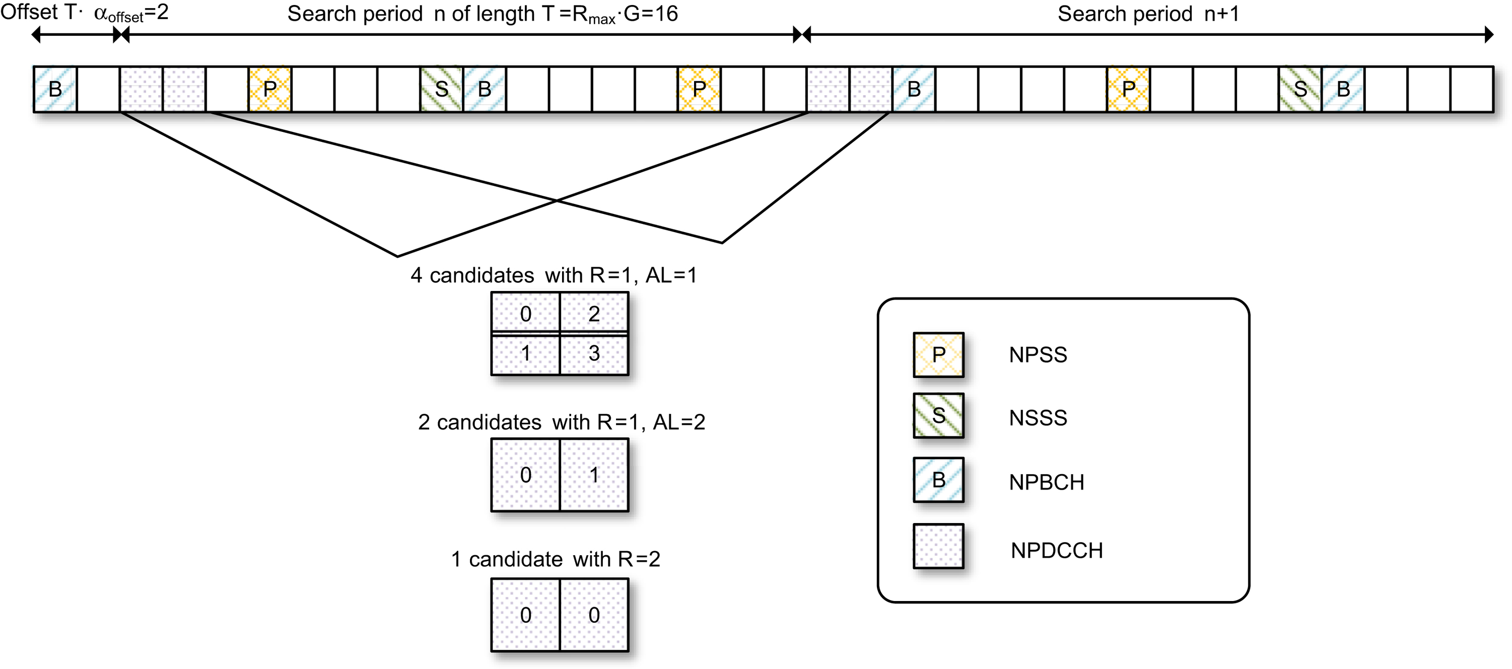
With these parameter settings, the search period is T
=
R
max
G
=
16 subframes. Fig. 7.56 illustrates the search periods according to this reference case. For this reference case, the starting subframes are the ones satisfying (SFN
×
10
+
SN) mod T
=
0, when the offset value is set to 0. According to the present example, the offset value is set to 1/8 of the search period, i.e., the starting subframe is shifted by two subframes.
According to Table 7.27, with R
max
=
2, the search space may have NPDCCH repetition factor of R
=
1 or 2. Furthermore, as indicated in Table 7.27, for the case of R
=
1, AL 1 may be used and thus both NCCE0 and NCCE1 (see Fig. 7.19 in Section 7.2.4.5) are each individually a search space candidate. For AL 2, NCCE0 and NCCE1 are used jointly as a
search space candidate. All the search space candidates are illustrated in Fig. 7.56, including the following set of seven candidates within a search period:
Table 7.27


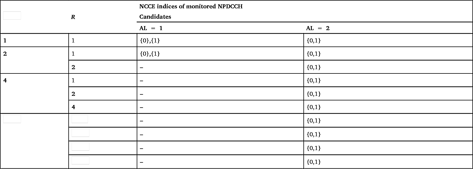
Table 7.28
It should be noted that the device needs to monitor a set of search space subframes that are not taken by NPBCH (subframe #0), NPSS (subframe #5), NSSS (subframe #9, in even-numbered SFN), and SIB1-NB.
The search space candidates shown in Table 7.27 to a large extent also applies to Type-2 CSS, with the only difference that Type-2 CSS candidates are only based on AL equal to 2. Furthermore, Type-2 CSS and USS share the same set of values for G, G
∈
{1.5, 2, 4, 8, 16, 32, 48, 64} [11]. Considering the maximum repetition factor of NPDCCH is 2048, the values of the search period for Type-2 CSS and USS are 4
<
T
≤
131,072.
7.3.2.2. Scheduling
In this section, we describe how scheduling for uplink and downlink transmissions works. When the network needs to schedule a device, it sends a DCI addressed to the device using one of the search space candidates that the device monitors. The C-RNTI, masking the DCI CRC, is used to identify the device. The NPDCCH carries a DCI that includes resource allocation (in both time and frequency domains), MCS, and information needed for supporting the HARQ operation. To allow low-complexity device implementation, Release 13 NB-IoT adopts the following scheduling principles:
- • A device only needs to support one HARQ process in the downlink.
- • A device only needs to support one HARQ process in the uplink.
- • The device need not support simultaneous transmissions of uplink and downlink HARQ processes.
- • Cross-subframe scheduling (i.e., DCI and the scheduled data transmission do not occur in the same subframe) with relaxed processing time requirements.
- • Half-duplex operation at the device (i.e., no simultaneous transmit and receive at the device) allows time for the device to switch between transmission and reception modes.
3GPP Release 14 introduces a device option of two simultaneously active HARQ processes in the downlink and uplink for Cat-NB2 devices, and Release 15 introduces TDD. We first describe the fundamental scheduling concept of NB-IoT using FDD networks and devices supporting only 1 HARQ process as examples. Aspects specific to devices supporting two HARQ processes and TDD are highlighted in Sections 7.3.2.2.3 and 7.3.2.2.4, respectively.
7.3.2.2.1. Uplink scheduling
DCI Format N0 is used for uplink scheduling. Table 7.29 shows the information carried in DCI Format N0.
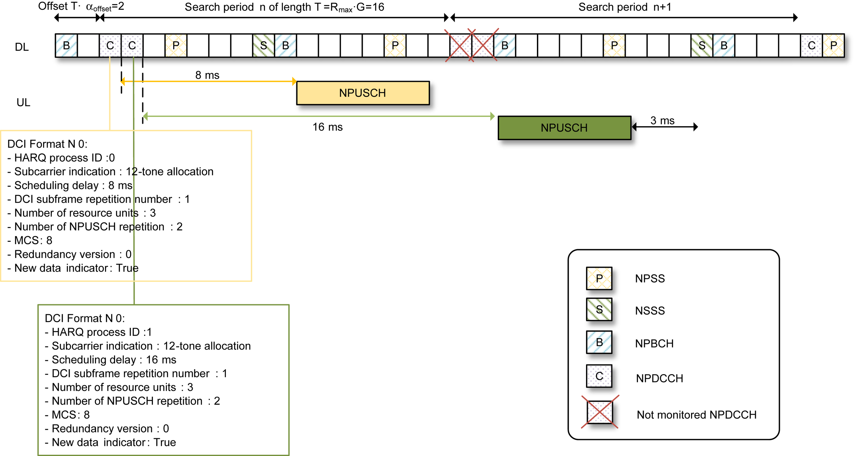
An uplink scheduling example is illustrated in Fig. 7.57 based on the same USS search space configuration example in Fig. 7.56. We will highlight a few important aspects in this example and relate them to the scheduling information presented in Table 7.29.
Table 7.29
| Information | Size [bits] | Possible settings |
|---|---|---|
| Flag for DCI format N0/N1 | 1 | DCI N0 or DCI N1 |
| Subcarrier indication | 6 |
Allocation based on subcarrier index.
3.75
kHz spacing: {0}, {1}, …, or {47}
15
KHz spacing:
1-tone allocation: {0}, {1}, …, or {11}
3-tone allocation: {0, 1, 2}, {3, 4, 5}, {6, 7, 8}, {9, 10, 11}
6-tone allocation: {0, 1, …, 5} or {6, 7, …, 11}
12-tone allocation: {0, 1, …, 11}
|
| NPUSCH scheduling delay | 2 | 8, 16, 32, or 64 (subframes) |
| DCI subframe repetition number | 2 | The R values in Table 7.27 |
| Number of RUs | 3 | 1, 2, 3, 4, 5, 6, 8, or 10 |
| Number of NPUSCH repetition | 3 | 1, 2, 4, 8, 16, 32, 64, or 128 |
| MCS | 4 | 0, 1, …, or 13, for indexing the row of the NPUSCH TBS table (see Section 7.2.5.2) |
| Redundancy version | 1 | Redundancy version 0 or 2 |
| New data indicator (NDI) | 1 | NDI toggles for new TB or does not toggle for same TB |
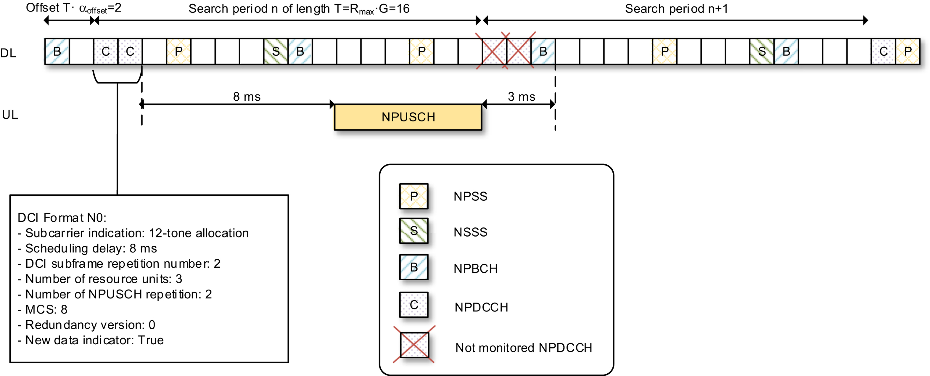
For uplink data transmissions, subframe scheduling with at least an 8
ms time gap between the last DCI subframe and the first scheduled NPUSCH subframe is required. This time gap allows the device to decode the DCI, switch from the reception mode to the transmission mode, and prepare the uplink transmission. This time gap is referred to as the scheduling delay and is indicated in DCI. After the device completes its NPUSCH transmission, there is at least a 3-ms gap to allow the device to switch from transmission mode to reception mode and be ready for monitoring the next NPDCCH search space candidate. This means that according to this example the network cannot use search period n+1 to send the next DCI to the device because the device will skip both search space candidates since they are both within the 3-ms gap from the end of its NPUSCH transmission. The network scheduler needs to follow this timing relationship in determining when to send the DCI to the device.
DCI Format N0 provides the information about the starting subframe as well as the total number of subframes of the scheduled NPUSCH resources. As mentioned earlier, the time gap between the last NPDCCH subframe carrying the DCI and the first scheduled NPUSCH slot is indicated in the DCI. However, how does the device know which subframe is the last subframe carrying the DCI? This potential problem is resolved by including the information of NPDCCH subframe repetition number in the DCI. With this information, if the device is able to decode the DCI using the first available subframe in the search space, it knows that the DCI will be repeated in one more subframe, which is then the last subframe carrying the DCI. Generally speaking, with the information of NPDCCH subframe repetition number, if the device is able to decode the DCI using any of the subframes of a search space candidate, it can unambiguously determine the starting and the ending subframes of this specific search space candidate.
The total number of scheduled NPUSCH slots is determined by the number of RUs per repetition, the number of repetitions, and the length of an RU. The length of an RU is inferred from the number of subcarriers used for NPUSCH Format 1 (see Section 7.2.5.2). According to the example, 12 subcarriers are used, and one RU for 12-tone NPUSCH Format 1 is 1
ms. Thus, with 2 repetitions and 3 RUs per repetition the total scheduled duration is 6
ms as illustrated in Fig. 7.57.
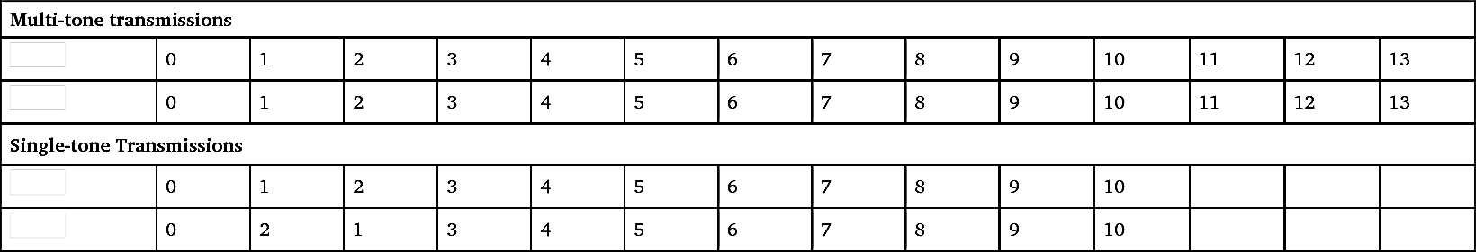
Modulation format is determined based on the MCS index, and the coding scheme is determined jointly based on the MCS index, number of RUs, and the redundancy version. According to the current example, the MCS index 8 is used. The MCS index is converted to a TBS index based on Table 7.30. Thus, MCS index 8 is mapped to TBS index 8, which, together
with the information that each repetition uses three RUs, is used to determine TBS as 392 based on Table 7.16. The number of data symbols per RU is determined based on Table 7.15 and is 144 symbols in this case. With QPSK and three RUs per repetition, there are overall 864 coded bits available. With TBS of 392 bits, code-word length of 864 bits, and redundancy version 0, using the rate matching framework of LTE, as detailed in Ref. [8], the code word can be generated accordingly.
Table 7.30


Because only one HARQ process is supported in Release 13, there is no need to signal the process number. From the device perspective, it only needs to know whether it needs to transmit the same or new TB. The HARQ acknowledgment is signaled implicitly using the n
ew data indicator (NDI) in the DCI. If the NDI is toggled, the device treats it as an acknowledgment of the previous transmission.
7.3.2.2.2. Downlink scheduling
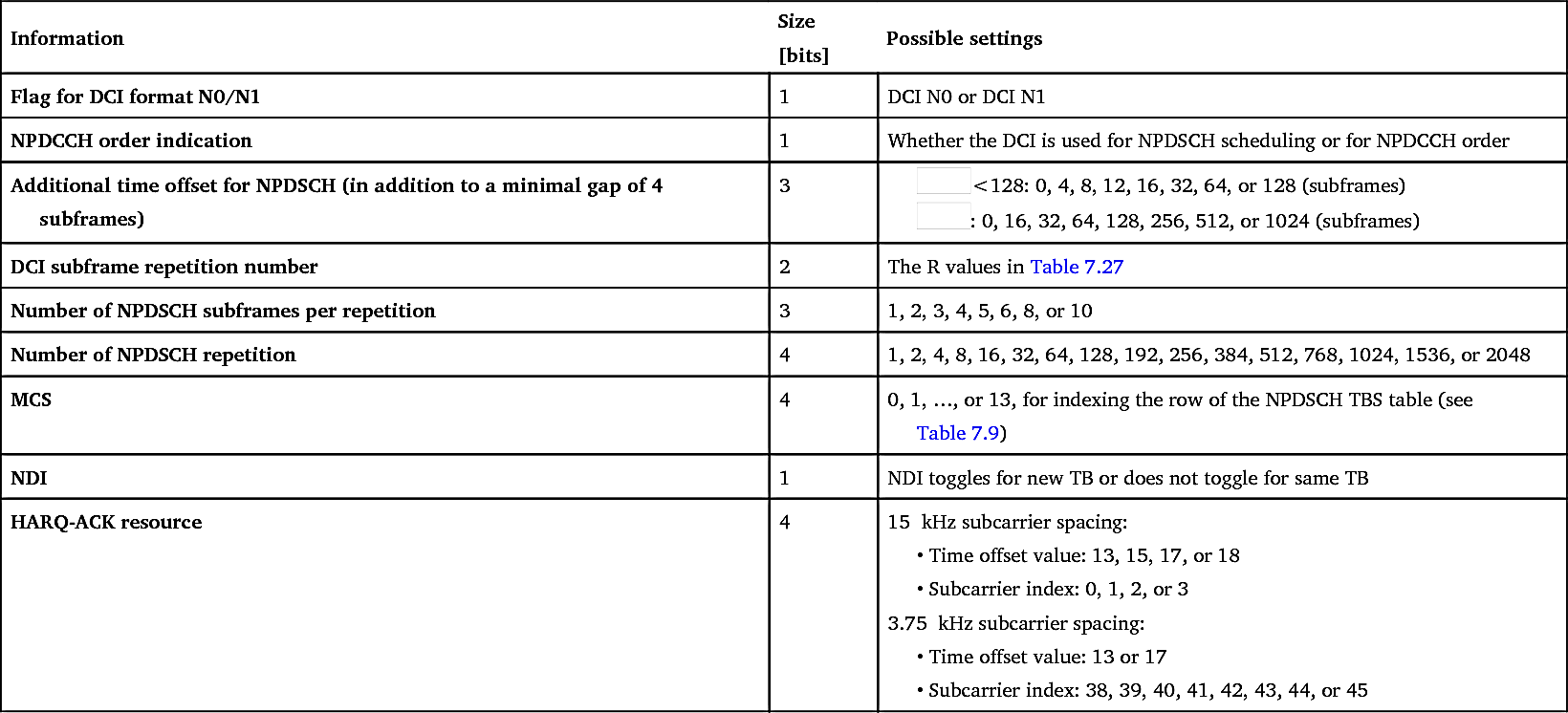
Scheduling of NPDSCH is signaled using DCI Format N1, which is shown in Table 7.31 including the parameter values of different information elements. Most of the general aspects
of downlink scheduling are similar to those used for uplink scheduling, although the exact parameter values are different. For example, cross-subframe scheduling is also used for downlink scheduling, but the minimum time gap between the last DCI subframe and the first scheduled NPDSCH subframe is 4
ms. Recall in the uplink cross-subframe scheduling case, this gap is at least 8
ms. A smaller minimum gap in the downlink case reflects that there is no need for the device to switch from receiving to transmitting between finishing receiving the DCI and starting the NPDSCH reception.
Table 7.31
| Information | Size [bits] | Possible settings |
|---|---|---|
| Flag for DCI format N0/N1 | 1 | DCI N0 or DCI N1 |
| NPDCCH order indication | 1 | Whether the DCI is used for NPDSCH scheduling or for NPDCCH order |
| Additional time offset for NPDSCH (in addition to a minimal gap of 4 subframes) | 3 |
<128: 0, 4, 8, 12, 16, 32, 64, or 128 (subframes) : 0, 16, 32, 64, 128, 256, 512, or 1024 (subframes)
 |
| DCI subframe repetition number | 2 | The R values in Table 7.27 |
| Number of NPDSCH subframes per repetition | 3 | 1, 2, 3, 4, 5, 6, 8, or 10 |
| Number of NPDSCH repetition | 4 | 1, 2, 4, 8, 16, 32, 64, 128, 192, 256, 384, 512, 768, 1024, 1536, or 2048 |
| MCS | 4 | 0, 1, …, or 13, for indexing the row of the NPDSCH TBS table (see Table 7.9) |
| NDI | 1 | NDI toggles for new TB or does not toggle for same TB |
| HARQ-ACK resource | 4 | 15
kHz subcarrier spacing: • Time offset value: 13, 15, 17, or 18 • Subcarrier index: 0, 1, 2, or 3 • Time offset value: 13 or 17 • Subcarrier index: 38, 39, 40, 41, 42, 43, 44, or 45 |
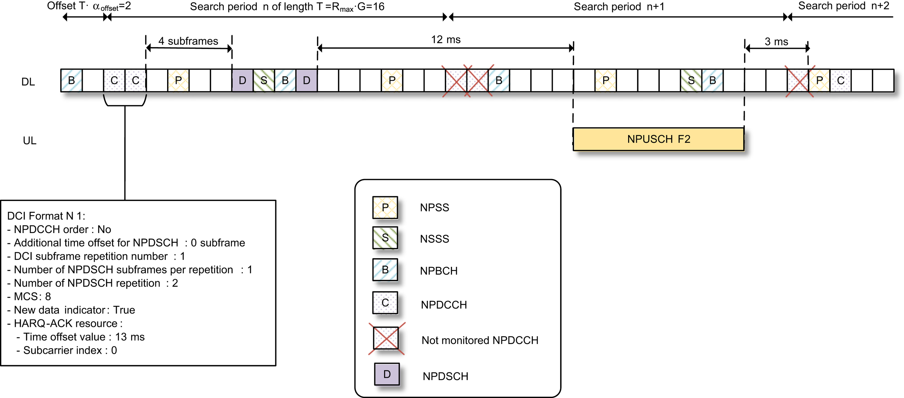
An NPDSCH scheduling example is illustrated in Fig. 7.58, again based on the same NPDCCH USS configuration example from Fig. 7.56. First, the DCI indicates that there is no additional scheduling delay, and thus the scheduled NPDSCH starts after a minimum gap of 4 downlink subframes following the last subframe carrying the DCI. The DCI also indicates that one subframe is used per repetition of NPDSCH and there are two repetitions. Based on this information, the device knows that there are two subframes scheduled for its NPDSCH reception. These two subframes are the first two available downlink subframes from the scheduled starting point of NPDSCH. The available subframes are the ones not used by NPBCH, NPSS, NSSS, or SIB1-NB and not indicated as invalid subframes. As illustrated, the first subframe after the scheduled NPDSCH starting point is available, but the next two subframes need to be skipped as they are used for NSSS and NPBCH and therefore are not considered as downlink subframes as far as downlink scheduling is concerned. After the NPBCH subframe, the next subframe is available.
A major difference between downlink and uplink scheduling is that in the downlink case, the scheduler also needs to schedule NPUSCH Format 2 resources for the signaling of HARQ feedback. This information is provided in the DCI in the format of a subcarrier index and a time offset. The time offset is defined between the ending subframe of scheduled NPDSCH and the starting slot of NPUSCH Format 2. NB-IoT requires such a time offset to be at least 13
ms, giving a gap of at least 12
ms between the end of NPDSCH and the start of NPUSCH Format 2, as indicated in Fig. 7.58. This gap is to allow sufficient NPDSCH decoding time at the device, time for switching from reception to transmission, and time for preparing the NPUSCH Format 2 transmission. As described in Section 7.2.5.2, NPUSCH Format 2 uses single-tone transmissions, either with 15 or with 3.75
kHz numerology. The RU for NPUSCH Format 2 is 2
ms for the 15
kHz subcarrier numerology or 8
ms for the 3.75
kHz numerology. Whether the device uses 15 or 3.75
kHz numerology for signaling HARQ feedback is configured through RRC signaling. Furthermore, the NPUSCH Format 2 transmissions may be configured with multiple repetitions. This information, however, is not included in the DCI but signaled separately through higher-layer signaling [27]. The example in Fig. 7.58 shows that the device is configured to use four repetitions for NPUSCH Format 2 (assuming the 15
kHz subcarrier numerology).
After the device completes its NPUSCH Format 2 transmission, it is not required to monitor NPDCCH search space for 3
ms. This is to allow the device to switch from the transmission mode to getting ready for receiving the NPDCCH again. According to the example in Fig. 7.58, the first subframe of search period n+2 is within the 3-ms gap and thus cannot be used for signaling a DCI to the device. The subframe immediately after the NPSS subframe is another NPDCCH search space candidate and is not within the 3-ms gap. Therefore, a DCI may be sent using this subframe.
7.3.2.2.3. Scheduling for Cat-NB2 devices supporting 2 HARQ processes
For a device in bad coverage, the physical layer throughput is limited by coverage in that its NPDCCH, NPDSCH, and NPUSCH all require large repetition factors and therefore it is the actual transmission time that limits the throughput. For a device in good coverage where repetition factor 1 is adequate, its throughput is then limited by the scheduling gaps that are designed for enabling low-cost device implementations as described in previous sections. As shown in Fig. 7.57 and 7.58, it takes a relatively long time to complete the delivery of a TB compared to the actual transmission time needed for NPDCCH, NPDSCH, or NPUSCH. Although NB-IoT is designed for allowing significant coverage extension, it should be noted that most of the devices in the network are actually within good coverage. It is thus desirable to improve the throughput for devices that are in good coverage. This may incentivize more capable devices to be introduced to the market.
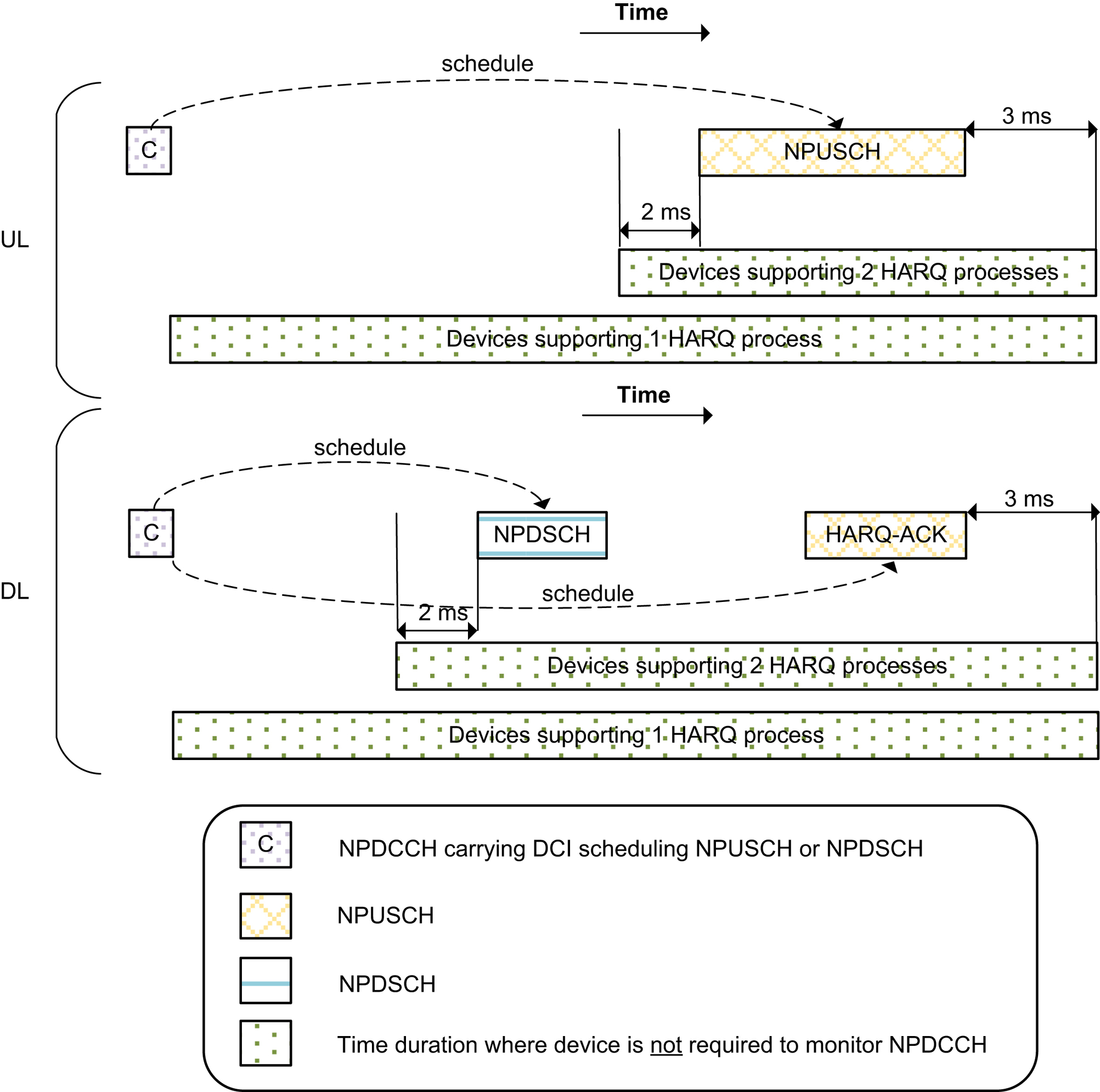
3GPP Release 14 introduces an option for Cat-NB2 devices to support two simultaneously active HARQ processes. This option allows two TBs to be delivered in the two simultaneously active HARQ processes. This in essence reduces the time gap between delivering multiple TBs. An uplink example is illustrated in Fig. 7.59. In this example, the device receives uplink scheduling for HARQ process ID #0 in the first NPDCCH subframe in search period n. The scheduled NPUSCH starts 8
ms after the NPDCCH subframe according to the information in the DCI. For devices supporting only one HARQ process, it is not required to monitor NPDCCH until 3
ms after the last scheduled NPUSCH subframe. Thus, for single-HARQ-process devices, the next TB can be scheduled using the first NPDCCH subframe in search period n+2 (i.e. the rightmost NPDCCH shown in Fig. 7.59). For devices supporting two HARQ processes, it is required to monitor NPDCCH until two subframes before the start of the NPUSCH already scheduled. Thus, in this example, the second NPDCCH subframe in search period n is still monitored by the device and therefore can be used to scheduled NPUSCH for another TB using HARQ process ID #1.
Similar tighening in NPDCCH monitoring also applies to downlink scheduling. Fig. 7.60 illustrates the difference in NPDCCH monitoring between devices supporting 1 HARQ and 2 HARQ processes. The new timing relationships deal with the inter-process switching. For each HARQ process though, the timing relationships are just as those of Release 13 for 1 HARQ process.
As mentioned in Section 7.2.4.5, for a device configured with two HARQ processes, one bit is added to DCI formats N0 and N1 to indicate the HARQ process number. In this case, DCI formats N0 and N1 become 24 bits long.
7.3.2.2.4. TDD scheduling methods
The scheduling methods in a TDD cell follow those described in previous sections for an FDD cell. The differences are summarized below.
- • For NPDSCH, the minimum gap between NPDCCH and NPDSCH in FDD is specified in terms of number of downlink subframes, whereas in TDD it is specified in terms of number of subframes. In other words, in the TDD case all the subframes are counted toward the minimum scheduling gap.
- • For NPUSCH, the scheduling delay is specified in terms of number of subframes in the FDD case, whereas in TDD it is specified in terms of number of uplink subframes. In other words, in the TDD case downlink and Special subframes are not counted toward the uplink scheduling delay.
7.3.2.3. Power control
NB-IoT supports open-loop power control. The decision to not allow closed-loop power control was based on the following considerations:
- • A data session for many IoT use cases is very short and thus not a good match for a closed-loop control mechanism, which takes time to converge.
- • Closed-loop power control requires constant feedback and measurements, which are not desirable from device energy efficiency point of view.
- • For devices in extreme coverage extension situations, the quality of channel quality measurements and reliability of power control command might be very poor.
Instead, NB-IoT uses open-loop power control based on a set of very simple rules. For NPUSCH, both Format 1 and Format 2, if the number of repetitions is greater than 2, the transmit power is the maximum configured device power, P
max. The maximum configured device power is set by the serving cell. If the number of NPUSCH repetitions is 1 or 2, the transmit power is determined by
 (7.20)
where P
target is the target received power level at the base station, L is the estimated path loss, α is a path loss adjustment factor, and M is a parameter related to the bandwidth of NPUSCH waveform. The bandwidth-related adjustment is used to relate the target received power level to target received SNR. The device uses the value of M according to its NPUSCH transmission configuration. The values of M for different NPUSCH configurations are shown in Table 7.32. The values of P
max, P
target, and α are provided by higher-layer configuration signaling.
The power control for NPRACH follows the same general principles. There may be multiple NPRACH configurations for supporting different coverage levels. The NPRACH preamble repetition levels may be different for these different NPRACH configurations. For NPRACH preambles not having the lowest repetition level, the maximum configured device power, P
max, is used in all transmissions. For NPRACH preambles having the lowest repetition level, the transmit power is determined based on the expression below.
 (7.21)
where P
target is the target NPRACH received power level, which is indicated by the higher layers [27]. If the device does not get a response and has not used the maximum configured device power, it can increase the target NPRACH received power level in its subsequent random access attempts until it reaches the maximum configured device power. This is referred to as power ramping.
7.3.2.3.1. Enhanced power control for transmitting random access preambles
As described earlier, for NPRACH preambles not having the lowest repetition level, the maximum configured device power, Pmax, is used in all transmissions. This simple rule makes
sense if a device uses a higher repetition level for sending an NPRACH preamble is for coverage extension.
Table 7.32
However, NB-IoT allows CE-level ramping in the random access procedure. With this, a device can switch to an NPRACH preamble configured for a higher coverage level after it has reached the maximum number of attempts and maximum transmit power level using NPRACH preambles configured for the lowest coverage level. One cause for the CE-level ramping may very well be because the coverage situation was worse than initially estimated by the device. However, another possible cause for the CE-level ramping is NPRACH collision during high network loads. In such a scenario, allowing a device to transmit an NPRACH preamble configured for a higher coverage level at its configured maximum power level does not help resolve the collision problem. Worse, it may result in a significant increase in inter-cell interference. To address this problem, enhanced random access power control was introduced in 3GPP Release 14. For devices supporting enhanced random access power control, open loop power control according to Eq. (7.21) and power ramping are used for NPRACH preambles when the random access procedure begins in CE level 0 or 1. If the procedure begins in CE level 2, the configured maximum transmit power is still applied.
7.3.2.3.2. Power head room
The device can include a power head room (PHR) report in its uplink transmission in Message 3 described in Section 7.3.1.6. A PHR report indicates the difference between the device's configured maximum transmit power level and its estimated required transmit power level for NPUSCH Format 1 which is the
P
t
a
r
g
e
t
+
α
L
 term in Eq. (7.20) for a nominal NPUSCH bandwidth and coverage level. The information about PHR helps the base station scheduler adjust the scheduled bandwidth as well as the MCS for the device. When a device has a positive PHR, it benefits from a higher bandwidth allocation and a higher MCS. In 3GPP Release 13, a PHR is quantized to 4 levels and included in the MAC control element named DPR (Data volume status and Power headroom Report). The 4-level quantization however results in too coarse granularity and leaves room for further enhancement. 3GPP Release 15 introduced enhanced PHR to enable the device to report its power headroom with 16-level quantization, which gives finer granularity and more detailed information for the base station scheduler to optimize the scheduling decision.
term in Eq. (7.20) for a nominal NPUSCH bandwidth and coverage level. The information about PHR helps the base station scheduler adjust the scheduled bandwidth as well as the MCS for the device. When a device has a positive PHR, it benefits from a higher bandwidth allocation and a higher MCS. In 3GPP Release 13, a PHR is quantized to 4 levels and included in the MAC control element named DPR (Data volume status and Power headroom Report). The 4-level quantization however results in too coarse granularity and leaves room for further enhancement. 3GPP Release 15 introduced enhanced PHR to enable the device to report its power headroom with 16-level quantization, which gives finer granularity and more detailed information for the base station scheduler to optimize the scheduling decision.7.3.2.4. Random access in connected mode
The base station can order a device to send an NPRACH preamble in connected mode by sending an NPDCCH order using DCI Format N1. This procedure can allow the base station and device to reacquire uplink time alignment. In this case, the exact resources for the device to transmit the NPRACH preamble are indicated in the DCI. Thus, the preamble is not subject to a collision. Table 7.33 lists the information included in an NPDCCH order.
7.3.2.5. Scheduling request
As NB-IoT was initially designed for use cases with devices transmitting or receiving infrequent, small data volume, there was no provisioning of scheduling request in connected mode when it was introduced. A scheduling request from the device can only be made by a random access procedure and including a data volume status report in Message 3 of the
random access procedure. To add to the versatility of NB-IoT and allow it to expand the use cases it can cater to, better supporting for long data sessions has been an interest. During a longer data session, the device may have bursty data arriving during connected mode. It is desirable for the device to be able to send its data volume status report without triggering a new random access procedure.
Table 7.33
| Information | Size [bits] | Possible settings |
|---|---|---|
| Flag for DCI format N0/N1 | 1 | DCI N0 or DCI N1 |
| NPDCCH order indication | 1 | Whether the DCI is used for NPDCCH order or for other purposes |
| Preamble format indicator | 1 | This information is included only for devices supporting the new NPRACH Format 2 introduced in 3GPP Release 15. The one bit information is to indicate whether the device should use Format 2 or not. |
| NPRACH configuration | 2 | Which NPRACH configuration to use. As mentioned in Section 7.2.5.4, each configuration is associated with a coverage class and has a specific repetition factor. |
| Subcarrier indication |
6 for Formats 0 & 1
8 for Format 2
|
For NPRACH Formats 0 and 1, 3.75 kHz subcarrier spacing is used and thus subcarrier index might be 0, 1, …, 47. For Format 2 with 1.25 kHz subcarrier spacing, subcarrier index might be 0, 1, …, 143. |
| Carrier indication | 4 | Which NB-IoT carrier to use |
3GPP Release 15 introduced a few options supporting the transmission of a scheduling request. The first option allows a device in connected mode to send scheduling requests in the form of buffer status report through periodic NPUSCH F1 resources. Such periodic NPUSCH resources can be activated and deactivated through dynamic signaling on NPDCCH. The second option allows a device to modify its NPUSCH F2 transmission by the application of a cover code on top of the Release 13 NPUSCH F2 waveform. The presence of the cover code indicates a scheduling request to the base station. Yet another option is for the device to send a scheduling request using a NPRACH transmission that is specifically preconfigured for the device.
7.3.2.6. Positioning
The capability of obtaining the positioning of a device is attractive as it opens new business opportunities such as people and goods tracking. Today such services are associated with solutions based on GPS, but since low cost is highly important for IoT devices, it is desired to be able to support positioning using the NB-IoT cellular technology. This facilitates a low cost device based on a single chip for both wireless connectivity and positioning services. Also, although GPS based solutions work perfectly well outdoors, they may have limitations in determining the position of devices indoors, where GPS coverage is limited.
The first solution designed for positioning of a device was enhanced cell identity which basically is based on the estimated TA that determines the round trip time between the device and the base station. It can be translated to the distance between the base station and device and allows improved positioning compared with only positioning a device based on the identity of the serving cell. Fig. 3.42 illustrates the positioning accuracy of enhanced cell identity and the impact from the synchronization accuracy of the device and the base station.
The second solution specified for NB-IoT is observed time difference of arrival (OTDOA). It is based on a device measuring the ToA on a set of downlink NPRS transmitted from a set of time-synchronized base stations surrounding the device. The device reports the narrowband positioning RSTD to a positioning server. Each RSTD allows the positioning server to determine the position of the device to a hyperbola centered around the base stations transmitting the NPRS. If RSTDs between three or more base stations are reported, the positioning server will be able to determine multiple hyperbolas and fix the position of the device to the intersection of the hyperbolas. Fig. 7.61 illustrates this, and the accuracy of the RSTD measurement is reflected by the width of the hyperbolas. High timing accuracy and many positioning base stations allowing multiple hyperbolas to be determined lead to a better positioning estimate.
7.3.2.7. Multicarrier operation
To support a massive number of devices, NB-IoT also includes a multicarrier feature from its very first release. In addition to the anchor carrier, which carries synchronization and broadcast channels, one or more non-anchor carriers can be provided. The notion of anchor and non-anchor carriers is explained in Section 7.2.1.1.
As a non-anchor carrier does not carry NPBCH, NPSS, NSSS, and SI, a Release 13 device in idle mode camps on the anchor carrier, monitoring the paging messages on the anchor. When the device needs to switch from idle to connected mode, the random access procedure also takes place on the anchor carrier. The network can use RRC configuration to point the device
to a non-anchor carrier. Essential information about the non-anchor carrier will be provided to the device using dedicated signaling. During the remaining duration of the connected mode, USS monitoring and NPDSCH and NPUSCH activities all take place on the assigned non-anchor carrier. After the device completes the data session, it comes back to camp on the anchor carrier during the idle mode.
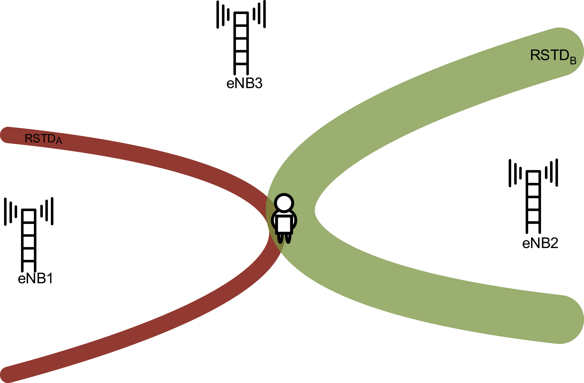
3GPP Release 14 enhanced non-anchor carrier operation to allow a device to monitor paging, initiate random access, and monitor RAR on a non-anchor carrier. More details on system access on a non-anchor carrier is provided in Section 7.3.1.10. A device can also receive single-cell multicast on a non-anchor carrier. Up to 15 downlink and uplink non-anchor carriers can be configured.
The non-anchor carriers can be allocated adapting to the traffic load of NB-IoT. Many IoT use cases generate highly delay-tolerant traffic. Such traffic can be delivered during off-peak hours in the network. The multicarrier feature allows the radio resources normally reserved for serving broadband or voice to be allocated for NB-IoT when the load of broadband and voice traffic is low. For example, during the middle of the night many of the LTE PRBs may be configured as non-anchor NB-IoT carriers serving the IoT traffic. The network can, as an example, take advantage of the multicarrier feature to push firmware upgrades to a massive number of devices during the middle of the night. An example of replacing LTE PRBs with non-anchor NB-IoT carriers during off-peak hours of broadband and voice traffic is illustrated in Fig. 7.62.
In 3GPP Releases 13 and 14, a stand-alone anchor carrier cannot be configured together with an in-band or guard-band non-anchor carrier. Similarly, a stand-alone non-anchor carrier cannot be configured together with an in-band or guard-band anchor carrier. This restriction is removed in 3GPP Release 15.