6.2 Basics of Creating and Configuring an Integration Flow
With SAP NetWeaver Developer Studio up and running and connectivity to the SAP NetWeaver AS Java established, we’ll now explore how to create and configure an iFlow.
6.2.1 Creating an iFlow
To create an iFlow, follow these steps:
- Switch to the SAP Process Integration Designer perspective.
- Establish a connection with the SAP NetWeaver AS Java with logon credentials (username and password maintained in the user management engine [UME]).
- Choose the PI Explorer tab.
-
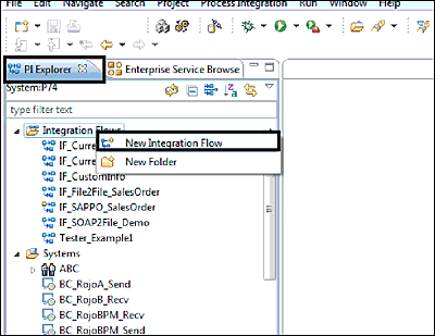
Right-click on the Integration Flows folder in the PI Explorer view, and choose the New Integration Flow option (see Figure 6.4).
Figure 6.4 Steps in Creating an iFlow
-
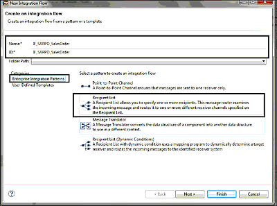
Depending on your requirements, choose an appropriate enterprise integration pattern or an existing user-defined template (see Figure 6.5). Here, we’ve selected Recipient List for demonstration purposes. Provide the required details, such as a Name and ID for your iFlow (Figure 6.5). Be aware that the ID name is automatically filled in based on the name of your iFlow. The iFlow ID must be unique and is restricted to a maximum of 32 characters.
Figure 6.5 Details for Creating an iFlow
- Skip configuring the sender or receiver details because this can be done after the iFlow is created.
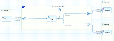
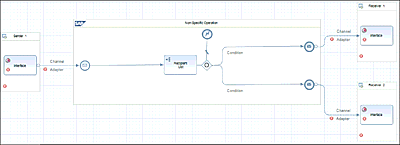
- Click on Finish. An iFlow will be created (see Figure 6.6). This iFlow can be further extended by performing configuration tasks, as discussed in the next section.
Figure 6.6 Sample Generated iFlow
6.2.2 Configuring an iFlow
For an iFlow to exchange messages between the connected business systems or communication components, a number of configuration steps have to be performed. A detailed step-by-step procedure is available in Section 6.3. For now, the essential and high-level configuration steps are as follows:
-
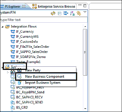
Create a business component (New Business Component) or import a business system from the SLD (Import Business System). The logic behind when to use a business system or business component was explored in Chapter 5. For simplicity’s sake, let’s locally create a business component as demonstrated in Figure 6.7.
Figure 6.7 Creating a New Business Component
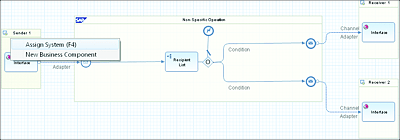
- Assign sender and receiver communication components. To assign the sender business system or component, right-click on Sender 1 and choose the Assign System (F4) option, as shown in Figure 6.8. You’ll need to repeat this step for every receiver system in your iFlow.
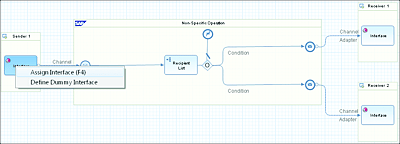
- Assign a service interface by right-clicking on the Interface icon and choosing the Assign Interface (F4) option, as shown in Figure 6.9.
-
Repeat this step for each receiver interface in your iFlow.
Figure 6.8 Assigning a Sender or Receiver System to the iFlow
Figure 6.9 Assigning a Service Interface to the iFlow
-
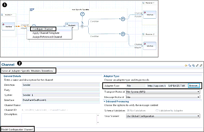
Configure the communication channel by right-clicking on the Channel line and selecting the Configure Channel option, as shown in Figure 6.10 1. You’re then taken to a new screen from which you can specify the communication channel details, such as adapter type 2. Further communication channel attributes can be configured in the Adapter-Specific, Modules, and Identifiers tabs and are self-explanatory.
Figure 6.10 Configuring the Communication Channel
Note
Be aware that in addition to the ability to configure a channel, you can also do the following:
- Repeat the previous step for the receiver channels.
-
Create rules and conditions for routing to the receivers. Right-click on the Recipient List box, as shown in Figure 6.11, and select one of the options in the context menu, depending of your requirement. Note that these conditions are based on XPath expressions.
Figure 6.11 Configure Routing and Conditions
- From the same context menu (Figure 6.11), you can also add or remove receivers, depending on your requirements.
-
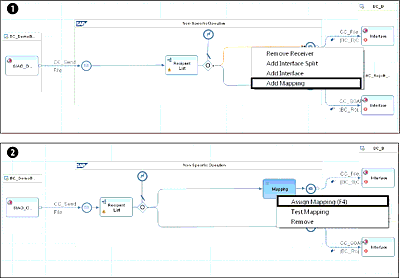
Assign the necessary mappings between the sender and receiver systems. To insert a mapping in the iFlow, right-click on the desired Condition line, and select the Add Mapping option, as shown in Figure 6.12 1. A new Mapping icon is added to the iFlow.
Figure 6.12 Adding a Mapping to the iFlow
- You then need to assign a specific operation mapping by right-clicking on the Mapping box and selecting the Assign Mapping (F4) option 2.
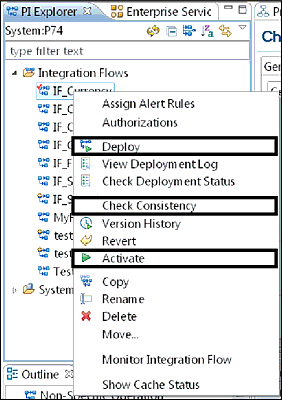
- Execute a consistency check to ensure that the iFlow has been correctly configured by right-clicking on the iFlow item from the PI Explorer view and selecting the Check Consistency option (see Figure 6.13). If the iFlow configuration isn’t complete, then the Problems view will be populated with error details.
-
Activate the iFlow by right-clicking and selecting the Activate option (see Figure 6.13).
Figure 6.13 Check Consistency of, Activate, and Deploy an iFlow
- Deploy your iFlow to the SAP PO server by right-clicking and selecting the Deploy option (Figure 6.13). It’s possible to monitor the deployment status via the Deployment Log view, as shown in Figure 6.14. If you encounter problems during the deployment, the error details will be accessible via this Deployment Log view. You can right-click on an entry and choose the View Deployment Trace option.
Figure 6.14 Deployment Log View
Note
If the iFlow hasn’t been properly configured, then red markers are shown on the different components, as shown in Figure 6.15. Until all these components are configured, the red markers will continue to appear, and you won’t be able to activate the iFlow.
Figure 6.15 Red Markers on Compulsory Components to be Configured
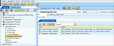
After a successful deployment, you can view the iFlow in the Integration Directory Swing user interface (UI) tool, as shown in Figure 6.16. The iFlow presented in the Interface Directory also includes the sender and receiver communication channels.
Figure 6.16 An iFlow in the Integration Directory
Also note that once deployed, the iFlow generates an ICO equivalent. SAP doesn’t recommend modifying the ICO generated by the iFlow from the Integration Directory (Swing client). Any changes made to the iFlow in the Swing client won’t reflect in the SAP NetWeaver Developer Studio. It’s therefore better to stick to SAP NetWeaver Design Studio for any iFlow-related activities.
