IN THIS CHAPTER
 Finding a place where you can build your mad-scientist laboratory
Investing in good tools
Picking out a good assortment of components to get you started
Iloved to watch Frankenstein movies as a kid. My favorite scenes were always the ones where Dr. Frankenstein went into his laboratory. Those laboratories were filled with the most amazing and exotic electrical gadgets ever seen. The mad doctor’s assistant, Igor, would throw a giant knife switch at just the right moment, and sparks flew, and the music rose to a crescendo, and the creature jerked to life, and the crazy doctor yelled, “It’s ALIVE!”
The best Frankenstein movie ever made is still the original 1931 Frankenstein,
directed by James Whale and starring Boris Karloff. The second-best Frankenstein movie ever made is the 1974 Young Frankenstein,
directed by Mel Brooks and starring Gene Wilder. Both have great laboratory scenes.
In fact, did you know that the laboratory in Young Frankenstein
uses the very same props that were used in the original 1931 classic? The genius who created those props was Kenneth Strickfaden, one of the pioneers of Hollywood special effects. Strickfaden kept the original Frankenstein props in his garage for decades. When Mel Brooks asked if he could borrow the props for Young Frankenstein,
Strickfaden was happy to oblige.
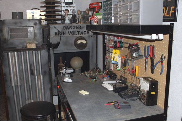
You don’t need an elaborate mad-scientist laboratory like the ones in the Frankenstein movies to build basic electronic circuits. However, you will need to build yourself a more modest workplace, and you’ll need to equip it with a basic set of tools as well as some basic electronic components to work with.
However, no matter how modest your work area is, you can still call it your mad-scientist lab. After all, most of your friends will think you’re a bit crazy and a bit of a genius when you start building your own electronic gadgets.
In this chapter, I introduce you to the stuff you need to acquire before you can start building electronic circuits. You don’t have to buy everything all at once, of course. You can get started with just a simple collection of tools and a small space to work in. As you get more advanced in your electronic skills, you can acquire additional tools and equipment as your needs change.
Equipping Your Mad-Scientist Lab
Like any hobby, electronics has its own special tools and supplies. Fortunately, you don’t need to run out and buy everything all at once. But the more involved
you get with the hobby, the more you will want to invest in a wide variety of quality tools and supplies. The following sections outline some of the essential stuff you’ll need at your disposal.
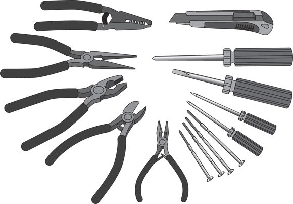
Basic hand tools
For starters, you’ll need a basic set of hand tools, similar to the assortment shown in Figure 3-3
. Specifically, you’ll need these items:
-
Screwdrivers:
Most electronic work is relatively small, so you don’t need huge, heavy-duty screwdrivers. But you should get yourself a good assortment of small- and medium-sized screwdrivers, both flat-blade and Phillips head.
A set of jeweler’s screwdrivers
is sometimes very useful. The swiveling knob on the top of each one makes it easy to hold the screwdriver in a precise position while turning the blade.
-
Pliers:
You will occasionally use standard flat-nosed pliers, but for most electronic work, you’ll depend on needle-nose pliers
instead, which are especially adept at working with wires — bending and twisting them, pushing them through holes, and so on. Most needle-nose pliers also have a cutting edge that lets you use them as wire cutters.
Get a small set of needle-nose pliers with thin jaws for working with small parts, and a larger set for bigger jobs.
-
Wire cutters:
Although you can use needle-nose pliers to cut wire, you’ll want a few different types of wire cutters at your disposal as well. Get something heavy-duty for cutting thick wire, and something smaller for cutting small wire or component leads.
-
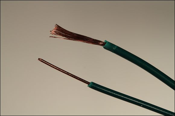
Wire strippers:
Figure 3-4
shows two pieces of wire that I stripped
(removed the insulation from). I stripped the one on top with a set of wire cutters and the one on the bottom with a set of wire strippers.
Notice the crimping in the one at the top, at the spot where the insulation ends? That was caused by using just a bit too much pressure on the wire cutters. That crimp has created a weak spot in the wire that may eventually break.
 To avoid damaging your wires when you strip them, I suggest you purchase an inexpensive (under $10) wire stripping tool. You’ll thank me later.
Magnifying glasses
One of the most helpful items you can have in your tool arsenal is a good magnifying glass. After all, electronic stuff is small. Resistors, diodes, and transistors are downright tiny.
Actually, I suggest you have at least three types of magnifying glasses on hand:
- A handheld magnifying glass
to inspect solder joints, read the labels on small components, and so on.
- A magnifying glass mounted on a base
so that you can hold your work behind the glass. The best mounted glasses combine a light with the magnifying glass, so the object you’re magnifying is bright.
-
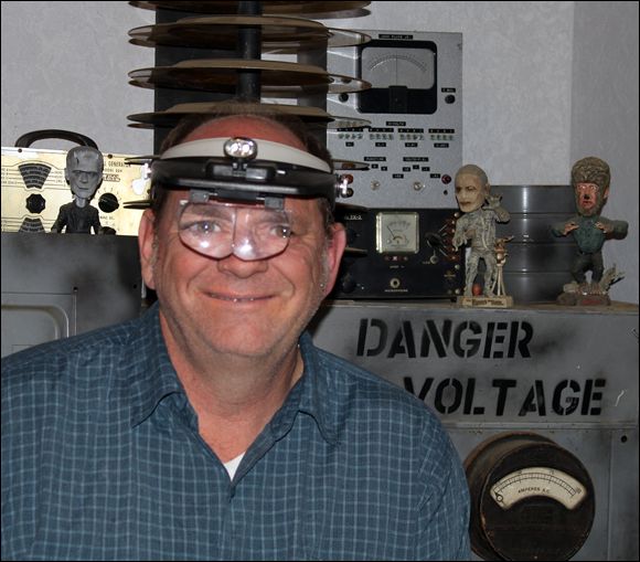
Magnifying goggles,
which provide completely hands-free magnifying for delicate work. Ideally, the goggles should have lights mounted on them. See Figure 3-5
.
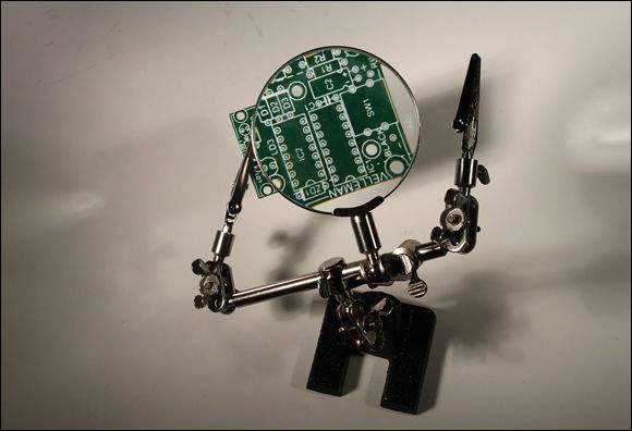
Third hands and hobby vises
A third hand
is a common tool amongst hobbyists. It’s a small stand that has a couple of clips that you use to hold your work, thus freeing up your hands to do delicate work. Most third-hand tools also include a magnifying glass. Figure 3-6
shows an inexpensive third-hand tool holding a circuit card.
The most common use for a third hand in electronics is soldering. You use the clips to hold the parts you want to solder, positioned behind the magnifying glass so you can get a good look.
Although the magnifying glass on the third hand is helpful, it does tend to get in the way of the work. It can be awkward to maneuver your soldering iron and solder behind the magnifying glass. For this reason, I often remove the magnifying glass from the third hand and use my favorite magnifying headgear instead.
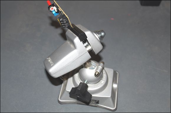
The third hand is often helpful for assembling small projects, but it lacks the sturdiness required for larger projects. Eventually you’ll want to invest in a small hobby vise such as the one shown in Figure 3-7
. This one is made by PanaVise (
www.panavise.com
).
Here are a few things to look for in a hobby vise:
-
Mount:
Get a vise that has a base with the proper type of workbench mount. There are three common types of mounts:
-
Bolt mount:
The base has holes through which you can pass bolts or screws to attach the vise to your workbench. This is the most stable type of mount, but it requires that you put holes in your workbench.
-
Clamp mount:
The base has a clamp that you can tighten to fix the base to the top and bottom of your workbench. Clamp mounts are pretty stable but can be placed only near the edge of your workbench.
-
Vacuum mount:
The base has a rubber seal and lever you pull to create a vacuum between the seal and the workbench top. Vacuum mounts are the most portable but work well only when the top of your workbench is smooth.
-
Movement:
Get a vise that has plenty of movement so that you can swivel your work into a variety of different working positions. Make sure that when you lock the swivel mount into position, it stays put. You don’t want your work sliding around while you are trying to solder on it.
-
Protection:
Make sure the vise jaws have a rubber coating to protect your work.
Soldering iron
Soldering
is one of the basic techniques used to assemble electronic circuits. The purpose of soldering is to make a permanent connection between two conductors — usually between two wires or between a wire and a conducting surface on a printed circuit board.
The basic technique of soldering is to physically connect the two pieces to be soldered, and then heat them with a soldering iron until they are hot enough to melt solder
(a special metal made of lead and tin that has a low melting point), then apply the solder to the heated parts so that it melts and flows over the parts.
Once the solder has flowed over the two conductors, you remove the soldering iron. As the solder cools, it hardens and bonds the two conductors together.
You learn all about soldering in Chapter 7
of this minibook. For now, suffice it to say that you need three things for successful soldering:
-
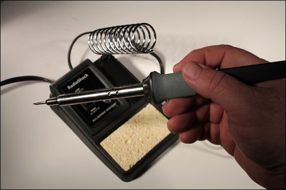
Soldering iron:
A little hand-held tool that heats up enough to melt solder. An inexpensive soldering iron from RadioShack or another electronics parts store
is just fine to get started with. As you get more involved with electronics, you’ll want to invest in a better soldering iron that has more precise temperature control and is internally grounded.
-
Solder:
The soft metal that melts to form a bond between the conductors.
-
Soldering iron stand:
To set your soldering iron on when you aren’t soldering. Some soldering irons come with stands, but the cheapest ones don’t. Figure 3-8
shows a soldering iron that comes with a stand. You can purchase this type of soldering iron from RadioShack for about $25.
Multimeter
In Chapter 2
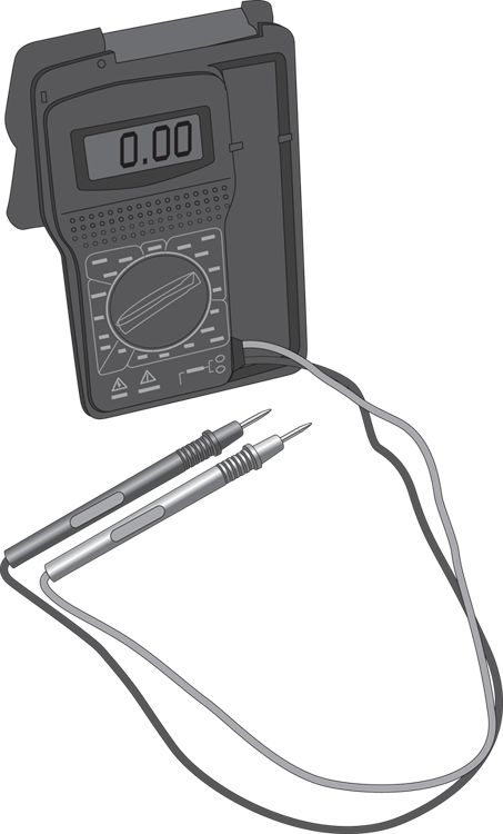
of this minibook, you learn that you can measure voltage with a voltmeter. You can also use meters to measure many other quantities that are important in electronics. Besides voltage, the two most common measurements you’ll need to make are current and resistance.
Rather than use three different meters to take these measurements, it’s common to use a single instrument called a multimeter
. Figure 3-9
shows a typical multimeter purchased from RadioShack for about $20.
Solderless breadboard
A solderless breadboard
— usually just called a breadboard
— is a must for experimenting with circuit layouts. A breadboard is a board that has holes in which you can insert either wires or electronic components such as resistors, capacitors, transistors, and so on to create a complete electronic circuit without any soldering.
When you’re finished with the circuit, you can take it apart, and then reuse the breadboard and the wires and components to create a completely different circuit.
Figure 3-10
shows a typical breadboard, this one purchased from RadioShack for about $20. You can purchase less expensive breadboards that are smaller, but this one (a little bigger than 7 x 4 inches) is large enough for all the circuits presented in this book.
What makes breadboards so useful is that the holes in the board are actually solderless connectors that are internally connected to one another in a specific, well-understood pattern. Once you get the hang of working with a breadboard, you’ll have no trouble understanding how it works.
Throughout the course of this book, I show you how to create dozens of different circuits on a breadboard. As a result, you’ll want to invest in at least one. I suggest you get one similar to the one shown in Figure 3-10
, plus one or two other, smaller breadboards. That way, you won’t always have to take one circuit apart to build another.
You can learn more about working with solderless breadboards in Chapter 6
of this minibook.
Wire
One of the most important items to have on hand in your lab is wire,
which is simply a length of a conductor, usually made out of copper but sometimes made
of aluminum or some other metal. The conductor is usually covered with an outer layer of insulation. In most wire, the insulation is made of polyethylene, which is the same stuff used to make plastic bags.
Wire comes in these two basic types:
-
Solid wire:
Made from a single piece of metal
-
Stranded wire:
Made of a bunch of smaller wires woven together
Figure 3-11
shows both types of wire with the insulation stripped back so you can see the difference.
For most purposes in this book, you’ll want to work with solid wire because it’s easier to insert into breadboard holes and other types of terminal connections. Solid wire is also easier to solder. When you try to solder stranded wire, inevitably one of the tiny strands gets separated from the rest of the strands, which can create the potential for a short circuit.
On the other hand, stranded wire is more flexible than solid wire. If you bend a solid wire enough times, you’ll eventually break it. For this reason, wires that are frequently moved are usually stranded.
Wire comes in a variety of sizes, which are specified by the wire’s gauge,
and is generally coiled in or on the packaging. Strangely, the larger the gauge number, the smaller the wire. For most electronics projects, you’ll want 20- or 22-gauge wire. You’ll need to use large wires (usually 14 or 16 gauge) when working with household electrical power.
Finally, you may have noticed that the insulation around a wire comes in different colors. The color doesn’t have any effect on how the wire performs, but it’s common to use different colors to indicate the purpose of the wire. For example, in DC circuits it’s common to use red wire for positive voltage connections and black wire for negative connections.
To get started, I suggest you purchase a variety of wires — at least four rolls: 20-gauge solid, 20-gauge stranded, 22-gauge solid, and 22-gauge stranded. If you can find an assortment of colors, all the better.
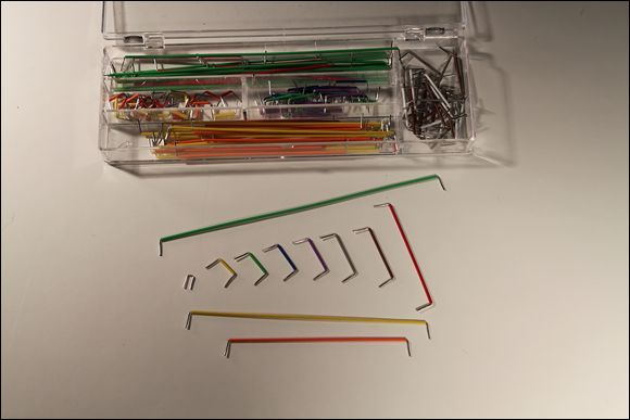
In addition to wires on rolls, you may also want to pick up jumper wires,
which are precut, stripped, and bent for use with solderless breadboards. Figure 3-12
shows an assortment I bought at RadioShack for about $6.
Batteries
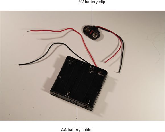
Don’t forget the batteries! Most of the circuits covered in this book use either AA or 9-volt batteries, so you’ll want to stock up.
If you want, you can use rechargeable batteries. They cost more initially, but you don’t have to replace them when they lose their charge. If you use rechargeables, you’ll also need a battery charger.
To connect the batteries to the circuits, you’ll want to get several AA battery holders. Get one that holds two batteries and another that holds four. You should also get a couple of 9-volt battery clips. These holders and clips are pictured in Figure 3-13
.
Other things to stock up on
Besides all the stuff I’ve listed so far, here are a few other items you may need from time to time:
-
Electrical tape:
Get a roll or two of plain black electrician’s tape. You’ll use it mostly to wrap around temporary connections to hold them together and keep them from shorting out.
-
Compressed air:
A small can of compressed air can come in handy to blow dust off an old circuit board or component.
-
Cable ties:
Also called zip ties
, these little plastic ties are handy for temporarily (or permanently) holding wires and other things together.
-
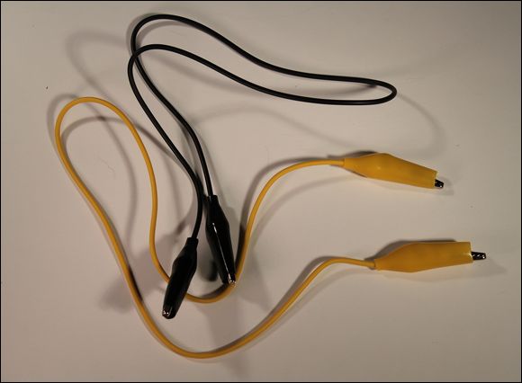
Jumper clips:
These are short (typically 12 or 18 inches) wires that have alligator clips
attached on either end, as shown in Figure 3-14
. You’ll use them to make quick connections between components for testing purposes.
Stocking up on Basic Electronic Components
Besides all the tools and supplies I’ve described so far in this chapter, you’ll also need to gather a collection of inexpensive electronic components to get you started with your circuits. You don’t have to buy everything all at once, but you’ll want to gather at least the basic parts before you go much farther in this book.
You can buy many of these components in person at any RadioShack store. If you’re lucky enough to have a specialty electronics store in your community, you may be able to purchase the parts there for less than what RadioShack charges. Alternatively, you can buy the parts online from
www.radioshack.com
or another electronic parts distributor.
Resistors
A resistor
is a component that resists the flow of current. It’s one of the most basic components used in electronic circuits; in fact, you won’t find a single circuit anywhere in this book that doesn’t have at least one resistor. Figure 3-15
shows three resistors, next to a penny so you can get an idea of how small they are. You’ll learn all about resistors in Book 2, Chapter 2
.
Resistors come in a variety of resistance values
(how much they resist current, measured in units called ohms and designated by the symbol  ) and power ratings
(how much power they can handle without burning up, measured in watts).
) and power ratings
(how much power they can handle without burning up, measured in watts).
All the circuits in this book can use resistors rated for one-half watt. You’ll need a wide variety of resistance values. I recommend you buy at least 10 each of the following 12 resistances:
You can save money by purchasing a package that contains a large assortment of resistors. For example, RadioShack sells a package that contains an assortment of 500 resistors — at least 10 of all values listed here, plus a few others, for under $15.
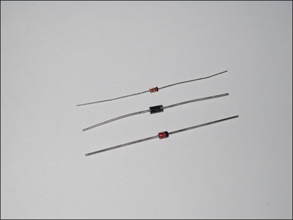
Diodes
A diode
is a device that lets current flow in only one direction. Figure 3-17
shows an assortment of various types of diodes.
A diode has two terminals, called the anode
and the cathode.
Current will flow through the diode only when positive voltage is applied to the anode and negative voltage to the cathode. If these voltages are reversed, current will not flow.
You learn all about diodes in Book 2, Chapter 5
. For now, I suggest you get at least five of the basic diodes known as the 1N4001 (the middle one in Figure 3-17
). You should be able to find these at any RadioShack.
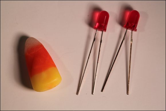
Light-emitting diodes
A light-emitting diode
(or LED
) is a special type of diode that emits light when current passes through it. You learn about LEDs in Book 2, Chapter 5
. Although there are many different types of LEDs available, I suggest you get started by purchasing five red diodes. Figure 3-18
shows a typical red LED.
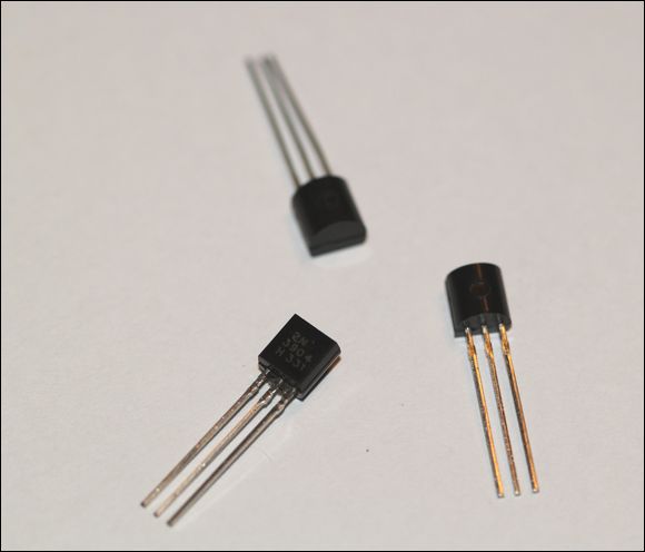
Transistors
A transistor
is a three-terminal device in which a voltage applied to one of the terminals (called the base
) can control current that flows across the other two terminals (called the collector
and the emitter
). The transistor is one of the most important devices in electronics, and I cover it in detail in Book 2, Chapter 6
. For now, you can just get a few simple 2N3904 NPN transistors, shown in Figure 3-19
, to have on hand.
 Don’t worry; by the time you finish Book 2, Chapter 6
, you’ll know what the designation 2N3904 NPN
means.
Don’t worry; by the time you finish Book 2, Chapter 6
, you’ll know what the designation 2N3904 NPN
means.
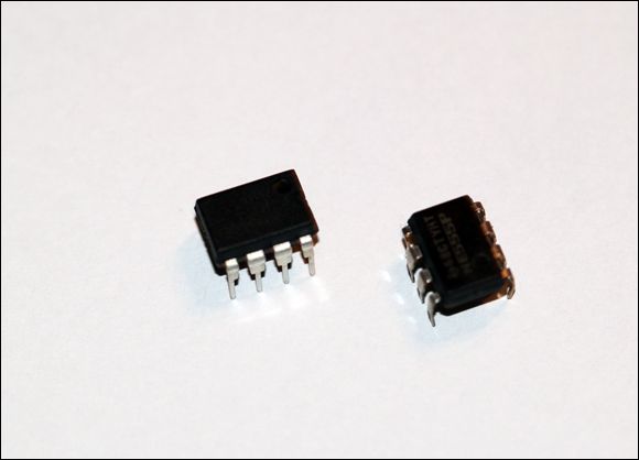
Integrated circuits
An integrated circuit
is a special component that contains an entire electronic circuit, complete with transistors, diodes, and other elements, all photographically etched onto a tiny piece of silicon. Integrated circuits are the building blocks of modern electronic devices such as computers and cellphones.
You learn how to work with some basic integrated circuits in Book 3
. To get started, you’ll want to pick up a few each of at least two different types of integrated circuits: a 555 timer and an LM741 op-amp. These chips are depicted in Figure 3-20
.
 It’s very important that the location you choose for your work area is secure, especially if you have young children around. Your work area will be filled with perils — things that can cause shocks, burns, and cuts, as well as things that under no circumstances should be ingested. Little hands are incredibly curious, and children are prone to put anything they don’t recognize in their mouths. So be sure to keep everything safely out of reach, ideally behind a locked door.
 -inch plywood. This will serve as a good solid work surface until you can acquire a real workbench.


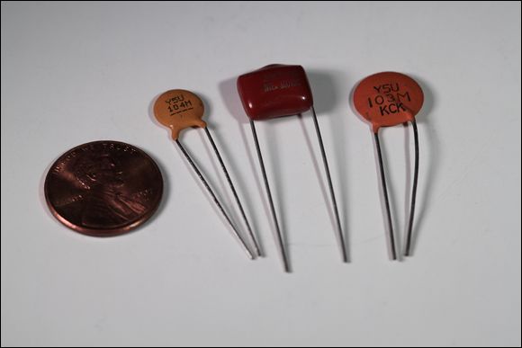
 . As a starting assortment of capacitors, I suggest you get at least five each of the following capacitors:
 and
and 
 ,
,  ,
,  ,
,  , and
, and